EP2543926A2 - Lens for bundling emitted light by means of a semiconductor light source (LED) - Google Patents
Lens for bundling emitted light by means of a semiconductor light source (LED) Download PDFInfo
- Publication number
- EP2543926A2 EP2543926A2 EP20120174888 EP12174888A EP2543926A2 EP 2543926 A2 EP2543926 A2 EP 2543926A2 EP 20120174888 EP20120174888 EP 20120174888 EP 12174888 A EP12174888 A EP 12174888A EP 2543926 A2 EP2543926 A2 EP 2543926A2
- Authority
- EP
- European Patent Office
- Prior art keywords
- light
- attachment
- optics
- boundary
- light source
- Prior art date
- Legal status (The legal status is an assumption and is not a legal conclusion. Google has not performed a legal analysis and makes no representation as to the accuracy of the status listed.)
- Withdrawn
Links
Images


Classifications
-
- F—MECHANICAL ENGINEERING; LIGHTING; HEATING; WEAPONS; BLASTING
- F21—LIGHTING
- F21S—NON-PORTABLE LIGHTING DEVICES; SYSTEMS THEREOF; VEHICLE LIGHTING DEVICES SPECIALLY ADAPTED FOR VEHICLE EXTERIORS
- F21S41/00—Illuminating devices specially adapted for vehicle exteriors, e.g. headlamps
- F21S41/30—Illuminating devices specially adapted for vehicle exteriors, e.g. headlamps characterised by reflectors
- F21S41/32—Optical layout thereof
- F21S41/33—Multi-surface reflectors, e.g. reflectors with facets or reflectors with portions of different curvature
- F21S41/334—Multi-surface reflectors, e.g. reflectors with facets or reflectors with portions of different curvature the reflector consisting of patch like sectors
- F21S41/336—Multi-surface reflectors, e.g. reflectors with facets or reflectors with portions of different curvature the reflector consisting of patch like sectors with discontinuity at the junction between adjacent areas
-
- F—MECHANICAL ENGINEERING; LIGHTING; HEATING; WEAPONS; BLASTING
- F21—LIGHTING
- F21S—NON-PORTABLE LIGHTING DEVICES; SYSTEMS THEREOF; VEHICLE LIGHTING DEVICES SPECIALLY ADAPTED FOR VEHICLE EXTERIORS
- F21S41/00—Illuminating devices specially adapted for vehicle exteriors, e.g. headlamps
- F21S41/10—Illuminating devices specially adapted for vehicle exteriors, e.g. headlamps characterised by the light source
- F21S41/14—Illuminating devices specially adapted for vehicle exteriors, e.g. headlamps characterised by the light source characterised by the type of light source
- F21S41/141—Light emitting diodes [LED]
- F21S41/143—Light emitting diodes [LED] the main emission direction of the LED being parallel to the optical axis of the illuminating device
-
- F—MECHANICAL ENGINEERING; LIGHTING; HEATING; WEAPONS; BLASTING
- F21—LIGHTING
- F21S—NON-PORTABLE LIGHTING DEVICES; SYSTEMS THEREOF; VEHICLE LIGHTING DEVICES SPECIALLY ADAPTED FOR VEHICLE EXTERIORS
- F21S41/00—Illuminating devices specially adapted for vehicle exteriors, e.g. headlamps
- F21S41/10—Illuminating devices specially adapted for vehicle exteriors, e.g. headlamps characterised by the light source
- F21S41/14—Illuminating devices specially adapted for vehicle exteriors, e.g. headlamps characterised by the light source characterised by the type of light source
- F21S41/141—Light emitting diodes [LED]
- F21S41/151—Light emitting diodes [LED] arranged in one or more lines
- F21S41/153—Light emitting diodes [LED] arranged in one or more lines arranged in a matrix
-
- F—MECHANICAL ENGINEERING; LIGHTING; HEATING; WEAPONS; BLASTING
- F21—LIGHTING
- F21S—NON-PORTABLE LIGHTING DEVICES; SYSTEMS THEREOF; VEHICLE LIGHTING DEVICES SPECIALLY ADAPTED FOR VEHICLE EXTERIORS
- F21S41/00—Illuminating devices specially adapted for vehicle exteriors, e.g. headlamps
- F21S41/20—Illuminating devices specially adapted for vehicle exteriors, e.g. headlamps characterised by refractors, transparent cover plates, light guides or filters
- F21S41/24—Light guides
-
- F—MECHANICAL ENGINEERING; LIGHTING; HEATING; WEAPONS; BLASTING
- F21—LIGHTING
- F21S—NON-PORTABLE LIGHTING DEVICES; SYSTEMS THEREOF; VEHICLE LIGHTING DEVICES SPECIALLY ADAPTED FOR VEHICLE EXTERIORS
- F21S41/00—Illuminating devices specially adapted for vehicle exteriors, e.g. headlamps
- F21S41/20—Illuminating devices specially adapted for vehicle exteriors, e.g. headlamps characterised by refractors, transparent cover plates, light guides or filters
- F21S41/285—Refractors, transparent cover plates, light guides or filters not provided in groups F21S41/24-F21S41/28
-
- F—MECHANICAL ENGINEERING; LIGHTING; HEATING; WEAPONS; BLASTING
- F21—LIGHTING
- F21S—NON-PORTABLE LIGHTING DEVICES; SYSTEMS THEREOF; VEHICLE LIGHTING DEVICES SPECIALLY ADAPTED FOR VEHICLE EXTERIORS
- F21S41/00—Illuminating devices specially adapted for vehicle exteriors, e.g. headlamps
- F21S41/30—Illuminating devices specially adapted for vehicle exteriors, e.g. headlamps characterised by reflectors
- F21S41/32—Optical layout thereof
- F21S41/322—Optical layout thereof the reflector using total internal reflection
Definitions
- the present invention relates to a front optics made of a transparent material for use in a light module of a motor vehicle headlight.
- the optical attachment is designed such that it bundles light emitted by at least one semiconductor light source to produce a predetermined light distribution with a light-dark boundary.
- the attachment optics comprises at least one light coupling surface for coupling at least part of the light emitted by the at least one semiconductor light source, reflecting interfaces for reflecting at least part of the injected light, and at least one light coupling surface for coupling at least part of the light coupled into the optical attachment, possibly after one Reflection at one of the at least one reflective interfaces.
- the subject of the invention is a light module of a Motor vehicle headlamps, wherein the light module comprises at least one semiconductor light source for emitting light and at least one of the at least one semiconductor light source associated auxiliary optics for focusing the light emitted from the at least one semiconductor light source and for generating a predetermined light distribution with a light-dark boundary.
- Light modules of a motor vehicle headlight which have light sources designed as semiconductor light sources, are known to have auxiliary optics of the type described above as primary optics for focusing the light emitted by the light sources.
- the semiconductor light sources are preferably designed as light-emitting diodes (LEDs).
- the attachment optics are arranged in front of them in a main emission direction of the semiconductor light sources, so that the light emitted by the semiconductor light sources is coupled into the attachment optics.
- the attachment optics preferably consist of a transparent material, in particular glass or plastic, and have reflective, in particular totally reflecting properties, on preferably laterally extending, funnel-shaped boundary surfaces.
- An optical attachment can be assigned one or more semiconductor light sources.
- Automotive headlamps can, especially if they are operated with semiconductor light sources, be of modular design, so that in the headlight, for example, a plurality of light modules are arranged, each having only a partial light distribution (Eg spotlight for illuminating a long range of a total light distribution or a base light distribution for illuminating the lateral areas of the total light distribution) of a desired overall light distribution (eg a dimmed light distribution, such as low beam, fog light, cornering light, etc.) produce.
- the partial light distributions are then superimposed to the desired complete light distribution.
- Each partial light distribution can be generated by a separate light module.
- the modular structure can also be implemented in a single light module, wherein different parts of the light module (so-called functional groups) form different partial light distributions, which are superimposed to the desired overall light distribution.
- a functional group comprises one or more semiconductor light sources that emit light that is shaped by the associated optical attachment to a partial light distribution.
- the diaphragm or diaphragm arrangement when it is arranged in the beam path, shadows a part of the light bundled by the primary optics, whereby one edge of the diaphragm or of the diaphragm arrangement forms the light-dark boundary of the light distribution.
- imaging optics a so-called secondary optics
- the shaded light distribution with the light-dark border in front of the vehicle can be projected onto the road.
- an edge of the diaphragm or diaphragm arrangement for generating the light-dark boundary is imaged on the road. This corresponds to the function of a known projection module of a headlight.
- a light distribution with a vertical bright-dark boundary can be generated by shading a portion of the collimated light by means of appropriately arranged and aligned aperture or aperture arrangements, a light distribution with a vertical bright-dark boundary, as for example.
- Masked high beam or partial high beam is used.
- the road ahead of the vehicle when there are no other road users in front of the vehicle, is standardly illuminated with a high beam distribution.
- suitable sensors for example in the form of a camera, objects are detected in an area in front of the vehicle. Then depending on the position of the detected objects from the high beam distribution targeted local areas are shadowed, in which there are detected objects. Around the area, the roadway can still be illuminated.
- the diaphragms represent additional components which also have to be partially adjusted by corresponding adjusting elements in order to achieve a desired variability of the light distribution.
- This increases the manufacturing costs of known light modules and headlights.
- light is shaded by the apertures, with the shaded light no contribution can do more to produce the light distribution, but is largely absorbed in the headlight.
- the efficiency of the known light module or headlight is thereby significantly deteriorated.
- the collecting lens can be arranged and configured such that it can directly image an edge of a semiconductor light source assigned to the attachment optics or an edge of the illumination surface of the semiconductor light source.
- the edge in front of the converging lens must be arranged at a distance from the converging lens, which is greater than the focal length of the converging lens.
- Such a punctiform light source would lead to the known intent optics to a narrow line-shaped image of the light, which leads to the generation of a light-dark boundary can be used.
- the line-shaped image would, for example, extend parallel to a horizontal axis on a measuring screen arranged at a distance from the optical attachment.
- light sources always have a longitudinal extension, preferably transverse to the optical axis of the optical attachment, so that in practice results in a softening of the thin line-shaped image in both the vertical and in the horizontal direction.
- the resulting light beam can thus be used at most to achieve a blurred light-dark boundary, wherein the degree of softening of the light beam depends on the size of the luminous area of the semiconductor light source and on the size of the light outcoupling surface of the optical attachment.
- the present invention has the object, a To create cost effective and efficient working optics, which can produce a light distribution with a sharp light-dark border without additional screens or aperture arrangements.
- the reflective interfaces of the optical attachment are divided into several areas, each of the areas is assigned to a defined point of a luminous surface of at least one semiconductor light source.
- the points associated with the areas comprise at least two spaced-apart points of the luminous area.
- the regions of the reflective interfaces are formed such that each of the regions generates the light-dark boundary of the light distribution or a part thereof.
- the defined points associated with the areas are preferably arranged on the edge of the luminous area.
- the luminous surface itself can have any shape, for example a circular or elliptical surface, or the shape of any polygon, in particular a rectangle or a square.
- the reflective interfaces may be formed by selecting a suitable material of the optical attachment and a suitable design and arrangement of the interfaces as total reflecting surfaces, so that in a sufficiently flat on the boundary surfaces incident light beams are totally reflected.
- the interfaces may also be formed as simply reflecting surfaces, for example by applying a reflective layer to the outside of the interfaces.
- Simply reflecting interfaces have the advantage that a reflection of the incident light is possible even then if the conditions of total reflection are not met.
- Total reflecting surfaces have the advantage of greater efficiency, since the Fresnel losses of the reflected light are lower.
- the intended regions of the reflective boundary surfaces are preferably designed such that the images of the luminous area of the at least one semiconductor light source generated by them produce a desired light distribution with a sharply imaging light-dark boundary.
- the design of the light incoupling surface and / or the light output surface of the attachment optics can thereby assist, i.
- the passing light rays break, so that the images produced by the light rays produce the sharp-imaging light-dark boundary.
- the at least one semiconductor light source assigned to the respective intent optics is an extended light source which has a certain areal extent.
- the intent optical system according to the invention can produce a light distribution with a particularly sharply defined light-dark boundary without the need for additional aids, for example diaphragms or diaphragm arrangements arranged in the beam path, for generating the light-dark boundary in the light module.
- the present invention is based on the idea of subdividing the interfaces of the optical attachment into several areas, each of the areas having a specific area Point of the luminous surface of the at least one semiconductor light source is assigned.
- the regions are each designed in such a way that a point of the area of the illuminated area of the at least one semiconductor light source produced by the interface region, which is closest to a light-dark boundary of the overall light distribution, is either at the light-dark boundary or closely below (at a horizontal light-dark boundary) or next to it (at a vertical light-dark boundary) of the light-dark boundary, if possible not beyond the light-dark boundary, ie not in the dark area of the light distribution, for example above a horizontal light-dark boundary.
- the complete overall light distribution can be generated by a single optical attachment. However, it can also be produced by an arrangement of several auxiliary optics, with the individual sub-light distributions generated by the auxiliary optics being superimposed or supplementing the overall light distribution.
- the auxiliary optics which generate the overall light distribution, be part of a single light module or different light modules.
- Each attachment optics may be associated with one or more semiconductor light sources. It is also possible that further, for example arranged in the optical attachment optical elements, contribute to the generation of the total light distribution of the light module or the motor vehicle headlight.
- the regions of the reflective boundary surfaces produce images of the luminous area of the at least one semiconductor light source which lie completely below a horizontal light-dark boundary or at most at a point on the light-dark boundary.
- a defined point of the luminous area which is assigned to at least one of the areas, corresponds to a specific corner of the luminous area of the semiconductor light source. It is assumed that a square, preferably square, configuration of the luminous surface of the semiconductor light source.
- a round contour of the luminous surface of the semiconductor light source would also be possible, in which case four (but also more or less) selectively selected points, if possible in a symmetrical arrangement, can be defined on the round luminous area and areas of the interface of the optical attachment can be assigned to these points become.
- the luminous area can also be designed as an arbitrary polygon, wherein the areas of the interface are assigned to selected (corner) points.
- each of the regions assigned to a defined point of the luminous area produces images of the luminous area on a measuring screen arranged at a distance from the optical attachment, wherein for all regions, when a horizontal bright-dark boundary is generated, the defined point of the luminous area assigned to a specific area is the uppermost point of the image generated by the area of the luminous surface forms.
- the uppermost point of the image produced by imaging the defined point of the luminous area is located just below or even at the light-dark boundary.
- the defined point assigned to a specific area forms the Luminous surface accordingly coming from the illuminated part of the light-dark boundary laterally closest to the light-dark boundary point of the generated image of the area of the luminous area.
- the point of the image produced closest to the light-dark boundary by the image of the defined point of the luminous area lies close to or even at the light-dark boundary on the illuminated part of the light distribution.
- a certain area of the boundary surface is assigned to a specific point of the luminous area if, for a horizontal light-dark boundary, an image of the point on a measuring screen arranged at a distance from the attachment optics forms the highest point of the resulting image of the luminous area.
- each of the regions of the totally reflecting interfaces assigned to a certain point must be designed, aligned and / or arranged in such a way that the uppermost point of the resulting image of the luminous area lies exactly at or as close as possible to the light-dark boundary.
- This automatically results in that light rays from the other corners and points of the luminous area after total reflection at the area associated with the particular point are all below the light-dark boundary.
- the optical attachment designed in this way almost the entire light coupled into the optical attachment can be used to generate the desired light distribution, since no light is shadowed, so that the optical attachment according to the invention has a particularly good efficiency.
- a semiconductor light source array consisting of several adjacent matrix and Semiconductor light sources arranged one above the other are preferably defined such that the respective outer corner points of the entire array are defined as the points assigned to the different regions of the interfaces.
- the intent optical system according to the invention is preferably configured not rotationally symmetrical.
- the total reflecting interfaces preferably have a funnel-shaped arrangement, wherein the diameter of the optical attachment increases transversely to the optical axis of the light input surfaces to the light outcoupling surfaces.
- the boundary surfaces are preferably subdivided into eight areas, with each corner point of a quadrangular luminous area being assigned in each case two of the boundary area areas.
- the intent optical system according to the invention is preferably configured not point-symmetrical.
- the regions of the totally reflecting boundary surfaces are preferably formed point-symmetrically in a plane perpendicular to the optical axis of the attachment optics, so that after rotation of the attachment optics by 180 ° around the optical axis, the original at the beginning of the rotation Design and arrangement of the interfaces results.
- a transition between the individual regions can be designed to be visible to the human eye as a kink, edge or step. However, it is also conceivable that the transitions between the various regions are hardly perceptibly fluent, ie without visible kinks, edges and steps.
- Boundary lines between the interface areas can be formed arbitrarily, for example, at least partially linear or hyperbolic.
- two interface areas lying diagonally opposite one another with respect to the optical axis can be assigned to the same point of the luminous area.
- the number of areas can deviate from eight areas, in order to achieve, for example, even more defined areas of particularly fine subdivided images of the illuminated area on the screen and thus also on the roadway.
- the areas of the totally reflecting interfaces are delimited by steps to each other. These steps result from the fact that the defined points of the luminous area, which are assigned to the individual areas of the interface, have a distance from each other and cause a shift of the image from one area to the next area.
- the luminous area is not assumed to be an idealized punctiform light source but rather a light source with a surface area, as it is given in practice.
- the steps between the individual interface areas could, however, be avoided, or at least reduced in height, if, in the transition between two adjacent or adjoining areas, the optimal target is to place the points of the illuminated area assigned to the areas as precisely as possible to the light-dark boundary , deviates.
- the defined points are then placed in the transition between two adjoining areas slightly below the horizontal Voloscuro boundary. This can be achieved, for example, by a rounding of the transition between two adjacent areas.
- the rounding blurs the strigoscuro limit to a certain extent, which in some Applications may even be desirable, for example, in low beam or fog light.
- the light-dark boundary remains substantially sharper than in the known auxiliary optics, as for example. From the DE 103 10 263 A1 or the DE 103 12 364 A1 are known.
- the total reflecting interfaces and / or the light outcoupling surfaces of the attachment optics are designed such that the attachment optics a light beam - at a horizontal light-dark boundary - diverging in the horizontal direction and / or - at a vertical light-dark boundary - with in the vertical direction of the Bright-dark border away and directed to the illuminated area of the overall light distribution towards divergent rays generated.
- a surface area of the light source is taken into account.
- the interface regions are formed, aligned and / or arranged such that the partial light distribution formed by the optical attachment produces the diverging light rays.
- the partial light distribution produced in this way can correspond to a spotlight distribution with, for example, a horizontal extent of approximately +/- 5 ° and a vertical extent of approximately 5 °.
- the interfaces can also do so be formed, aligned and / or arranged that the resulting partial light distribution is further stretched and, for example, even generates a basic light distribution for low beam, which arranged on a at a distance to the illumination device with the optical attachment according to the invention, vertical screen, for example, a horizontal extension of approx +/- 28 ° and a vertical extent of about 7 °.
- a first light beam is formed, in particular, by light beams which are emitted obliquely by the semiconductor light source and are coupled into the attachment optics via the coupling surfaces that are approximately vertical (parallel to the optical axis of the attachment optics). After the coupling, these light beams strike the areas of the totally reflecting boundary surfaces and are totally reflected there at least once and directed to the light output surface.
- a second light beam is formed by the semiconductor light source in approximately parallel to the main emission direction emitted light beams, which are coupled by approximately horizontally (perpendicular to the optical axis of the optical attachment) arranged coupling surfaces in the optical attachment and reach a total reflection at the interfaces to the decoupling surface.
- a directly imaging lens is preferably provided in the optical attachment, for example, at the light coupling surfaces and / or the light coupling surfaces, which bundles the light without reflection at the interfaces, in particular largely collimated (parallelized).
- This second light beam must also produce the desired light-dark border. Therefore, the lens formed in the optical attachment is arranged and shaped for light beams emitted essentially parallel to the optical axis or to the main emission direction such that an edge of the luminous area of the at least one semiconductor light source is imaged as a light-dark boundary of the resulting light distribution or as a part thereof.
- this second light bundle can supplement or support the first light bundle generated by reflection at the totally reflecting boundary surfaces during the generation of the light-dark boundary. Since the intent optics designed in this way directs and shapes the light beams of the two light bundles independently of each other, so that both light bundles complement each other to the desired partial light distribution, the optical attachment is very compact and advantageously requires little installation space.
- the light output surface of the attachment optics comprises curved surfaces, in particular cylindrical lenses or cylindrical lens segments, whose cylinder axis preferably extends transversely to the course of the light-dark boundary.
- curved surfaces in particular cylindrical lenses or cylindrical lens segments, whose cylinder axis preferably extends transversely to the course of the light-dark boundary.
- the curved surfaces can not only generate diverging (scattering) rays, but also converging (bundling) rays.
- Converging and diverging light beams are suitable, for example, for generating a fog light distribution, a basic light distribution of a low beam or a cornering light distribution, in each case in order to achieve the widest possible light distribution and thereby to improve the driver's view in the corresponding driving situations.
- such a scattering of the light can alternatively also by a corresponding configuration of the light incoupling surface, the total reflecting interface, and / or arranged in the interior of the optical attachment lens, so without corresponding design of the light outcoupling surfaces are designed.
- the totally reflecting interface with correspondingly formed facets, which form the light already in the optical attachment accordingly, so that it is scattered after passing through the light coupling-out surfaces.
- an additional, separately manufactured optical element with refractive and / or reflective properties is arranged in front of the light outcoupling surface in order to shape the decoupled light of the optical attachment after emerging from the optical attachment.
- the total reflecting interfaces comprise at least one interface running obliquely to an optical axis of the attachment optics, which deflects the light passing through the attachment optics onto the light extraction surface, wherein an exit direction of the light from the attachment optics is at an angle is directed to the optical axis and thus to the main exit direction of the light rays from the at least one light source.
- the light can also be reflected by total reflection at the inclined boundary surface and, depending on the design of the inclined boundary surface, can produce a scattering or bundling of the light.
- the light emerging from the optical attachment at any angle to the main emission direction of the semiconductor light source preferably pivoted by 90 °, can escape.
- Such an embodiment could allow, for example, a better positioning of the attachment optics in the light module, whereby advantageously a predetermined space in the headlight space could be better used.
- At least one of the regions of the totally reflecting boundary surfaces has steps.
- a wider shape of the attachment optics can be achieved, wherein the attachment optics, for example, can be fitted flush in a given installation space.
- the distance of the areas of the interfaces to the light source can be changed, whereby the images of the luminous area can optionally be increased or decreased.
- a zone of maximum light intensity in the generated partial light distribution can thereby be selectively shifted.
- the step-shaped formation may concern individual sections of the totally reflecting interfaces, but of course it may also relate to an entire interface.
- the attachment optics together with the semiconductor light source is rotated so that the assignment of the regions of the totally reflecting boundary surfaces to the defined points of the luminous area of the semiconductor light source is maintained. This possibility can be used particularly advantageous if the desired overall light distribution by Overlay several sub-light distributions is generated.
- a first headlamp module with a first intent optic may create a horizontal portion of an asymmetric Cadoscuro boundary
- another headlamp module with a 15 degree rotated intent optic may produce the 15 degree increase in the light-dark boundary.
- the resulting light distribution with the asymmetrical light-dark boundary is thus composed of the light of two optical head units and can be used, for example, for a spotlight distribution as part of a low beam distribution or a finished low beam distribution. If the resulting light distribution is a spotlight distribution, another module could generate a base light distribution such that a superposition of the spotlight distribution and the basic light distribution produces the resulting total low beam distribution that meets the legal requirements.
- a vertical bright-dark boundary can be generated, which can also be modularly integrated into an overall system for generating an overall light distribution, for example in the form of a partial high-beam.
- At least one of the attachment optics is preferably pivotable together with the at least one semiconductor light source associated therewith about an axis of rotation that runs transversely to the optical axis of the attachment optics.
- the intent optical system according to the invention can also be used for the realization of dynamic light functions. In this case, no modifications to the attachment optical system according to the invention itself must be made.
- the drive elements necessary for setting the dynamic light functions can thereby attack directly on the attachment optics.
- a dynamic headlamp leveling can be realized, in which an adaptation of the bright-dark boundary is realized at a pitch angle of the vehicle.
- a horizontal pivoting of the attachment optics about a vertical axis a dynamic cornering light, in which when cornering a main emission or the optical axis of the attachment optics is given away in the direction of a curve inside.
- the above-described rotation of the optical attachment to the optical axis is also possible while driving, for example, in a highway driving the 15 degree increase in asymmetric light-dark boundary of a low-beam distribution while driving can be reduced, for example, be reduced to zero degrees, so that a continuous horizontal Patoscuro border arises, as is advantageous, for example, in a motorway light distribution.
- the optical axis of the optical attachment could be increased to increase the range of the emitted light distribution during a highway ride. In another application, it is e.g.
- Light modules of a motor vehicle headlight or a motor vehicle light which are operated with semiconductor light sources, often have attachment optics for focusing the light emitted from the light source.
- the attachment optics are made of a transparent material, especially glass or plastic.
- the light to be focused of the light source is at least partially coupled into at least one light input surface in the intent optics, partially reflected at lateral interfaces of the optical attachment total and finally decoupled the coupled light via at least one Lichtauskoppel types from the attachment optics. Bundling of the light is achieved by refraction at the Lichteinkoppel- and / or Lichtauskoppel inhabit and / or by total reflection at the lateral interfaces.
- An optical attachment can be assigned one or more semiconductor light sources.
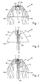
- FIGS. 1 to 5 show an example of a known from the prior art intent optics 10 with exemplified light beam progressions.
- the attachment optics 10 is a semiconductor light source 12, which is preferably designed as a light emitting diode assigned.
- FIG. 1 1 shows a first possible beam path of the light emitted by the semiconductor light source 12 within the optical attachment 10.
- the semiconductor light source 12 is arranged relative to the attachment optics 10 such that as much emitted light of the semiconductor light source 12 radiates in the direction of light coupling surfaces 14 of the attachment optics 10.
- a preferably cylindrical or frustoconical recess 11 is formed on the back of the attachment optics 10, in which the light source 12 is arranged.
- the recess comprises lateral, light coupling surfaces 14a, which extend approximately parallel or at a small angle to an optical axis 20 of the optical attachment 10.
- the Lichteinkoppel vom 14a correspond to a jacket of a recess 11 forming cylinder or a truncated cone.
- the recess 11 preferably has a circular cross-section. Of course, the recess 11 may also have an oval or polygonal cross-section.
- a main emission direction of the light emitted by the light-emitting diode 12 extends substantially parallel to the optical axis 20 of the attachment optics 10.
- a first ray path of the light comprises light beams of the semiconductor light source 12 which are emitted obliquely to the main emission direction and are coupled into the attachment optics 10 at the lateral light coupling surface 14a , The light coupled to the light coupling surfaces 14a then strikes boundary surfaces 16 of the attachment optics 10, where it is reflected by total reflection and deflected in the direction of outcoupling surfaces 18a.
- the light can be bundled, preferably parallelized (collimated). Subsequently, the bundled light at the light output surfaces 18a of the optical attachment 10 is coupled out of this. In this case, the light totally reflected at the boundary surfaces 16 preferably emerges from the attachment optics at decoupling surfaces 18a arranged at a distance from the optical axis 20. Both when entering through the light coupling surfaces 14a and when exiting through the light output surfaces 18a, the light can be refracted, which can be used in addition to the bundling of light. After decoupling from the optical attachment 10, the light beams are substantially parallel.
- FIG. 2 shows a second possible beam path of the emitted light from the semiconductor light source 12 within the attachment optics 10.
- light emitted by the light emitting diode 12 substantially parallel to the main emission direction, via a substantially transverse to the optical axis 20 extending light input surface 14b at the bottom of Well 11 coupled into the optical attachment 10.
- the second beam path of the light runs within the attachment optics 10 substantially along the optical axis 20 of the attachment optics 10.
- the emitted light of the semiconductor light source 12 can meet directly behind the light coupling surface 14 on a lens 22 arranged there, the light, possibly in cooperation with the transverse to the optical axis 20 extending light input surface 14b, bundles, preferably parallelized.
- the lens 22 may also be an integral part of the light input surface 14b. Subsequently, the light strikes a central light output surface 18b, through which the optical axis 20 passes. This too Light is decoupled in a parallel direction at the light outcoupling surface 18b, analogous to the first beam path. In a real operation of the attachment optics 10 both ray trajectories take place simultaneously.
- FIG. 3 shows the interaction of the first and the second beam path in the known optical attachment 10th
- the boundary surfaces 16 and / or the light output surfaces 18 By deforming the light input surfaces 14, the boundary surfaces 16 and / or the light output surfaces 18, the beam path through the optical attachment 10 and thus the light distribution generated can be influenced. So are in FIG. 4 the boundary surface 16 more concave curved than in the FIGS. 1 to 3 shown intent optics 10 and the light output surfaces 18 are also slightly convex curved.
- FIGS. 1 to 4 has been assumed by an ideal point light source.
- the semiconductor light source 12 is an areally extended light source with corresponding surface dimensions.
- FIG. 5 shows such a realistic formed semiconductor light source 12 with the resulting due to the surface extension of the light source 12 beam paths.
- the light distribution is widened and scattered.
- the result of this shape of the surfaces can not produce a sharp gradient of light intensity in the resulting light distribution, for example, to produce a sharp light-dark boundary 42 (see Figures 14 . 20 and 23 ) necessary is.
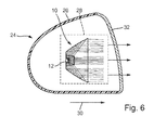
- FIG. 6 shows a headlight according to the invention 24 in a vertical longitudinal section.
- the headlight 24 includes a housing 26 in which a light module 28 for generating a partial light distribution is arranged.
- the light module 28 is preferably used to generate a dimmed partial light distribution with a horizontal light-dark boundary, such as a spotlight distribution or a basic light distribution of a low beam or a fog light.
- the module 28 can also be designed to generate a light distribution with a vertical light-dark boundary, as it is, for example, in a Operafernlicht application.
- An overall light distribution produced by the headlight 24 is preferably obtained by superposing the partial light distribution produced by the module 28 with other partial light distributions generated by other light modules (not shown) arranged in the housing 26.
- the partial light distribution generated by the light module 28 forms the overall light distribution of the headlamp 24 without overlapping with other partial light distributions.
- the headlamp 24 may additionally also comprise any luminaire modules for generating any desired luminaire functions (for example flashing light, daytime running light, parking light, position light).
- the housing 26 of the headlamp 24 has in the light exit direction 30 on a light exit opening, which is closed with a translucent cover 32 to prevent the ingress of dirt and moisture.
- the cover 32 may be formed as a so-called. Clear disc without optically active elements or as a so-called. Lens which is at least partially provided with optically active elements, for example in the form of cylindrical lenses or prisms.
- the light module 28 has the semiconductor light source 12, to which a front attachment 10 according to the invention is assigned.
- the light module 28 may also include a plurality of semiconductor light sources 12 each having an associated attachment optics 10. It is also possible for a plurality of semiconductor light sources 12 to be assigned to a common optical attachment 10.
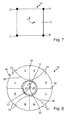
- FIG. 7 shows a plan view of an exemplary luminous surface 13 of the semiconductor light source 12 in a schematic representation.
- the luminous surface 13 has in this embodiment, a quadrangular, substantially square contour, wherein the four vertices of the luminous surface 13 are denoted by the letters A-D.
- Another polygonal contour of the luminous surface 13 is also possible. Even a round or oval contour of the luminous surface 13 would be possible.
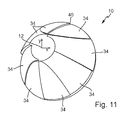
- FIG. 8 shows a rear view in the light exit direction 30 as viewed on the attachment optics 10 according to the invention.
- the luminous area 13 of the semiconductor light source 12 is marked with the vertices A to D.
- An essential aspect of the present invention is the subdivision of the boundary surfaces 16 of the optical attachment 10 into a plurality of regions 34, each of which is associated with defined, mutually spaced points of the luminous surface 13. These are preferably arranged along the outer edges of the luminous surface 13. Particularly preferably, the regions 34 are assigned to the corner points A to D of the luminous surface 13 of the semiconductor light source 12. In a round or oval configuration of the luminous surface 13, the points assigned to the regions 34 can be defined as desired, preferably along the outer edges of the luminous surface 13.
- the defined points A to D of the luminous surface 13 are arranged as uniformly as possible spaced apart along the outer edge and each two of the points A to D are arranged diagonally opposite to each other with respect to a center of gravity of the luminous surface 13, respectively.
- the interface 16 is divided into eight regions 34.
- the regions 34 are partly separated by linear boundary lines 36 or by substantially hyperbolic boundary lines 38 due to their construction.
- the boundary surface 16 can be separated along the borderlines 36 and 38.
- Each of the demarcated areas 34 is associated with a specific corner A to D of the luminous area 13 of the semiconductor light source 12.
- the individual areas 34 respectively associated corner A to D of the luminous surface 13 is illustrated by indicating the name of the corner A to D.
- the shape of the boundary line 36; 38 is determined in particular by the condition that only one corner A of a region 34; B; C or D produces the highest point of the image with respect to the Patoscuro boundary.
- the course of the boundary lines 36, 38 is as shown. If the light source 12 has a different shape, a different course of the boundary lines 36, 38 may result.
- the assignment of the points A to D of the luminous surface 13 to the interface regions 34 takes place according to the following principle:
- the regions 34 generate images of the luminous surface 13 of the semiconductor light source 12 on a measuring screen arranged at a distance from the attachment optics 10.
- the images generated by the individual regions 34 are in the FIGS. 9 and 10 drawn by way of example and designated by the reference numeral 35. It will be appreciated that due to the curvature of the regions 34, the images are partially distorted and / or rotated. Due to the curvature you can not turn images.
- the orientation of the images results from the position / shape of the light source 12 and the viewing angle, in which one looks at the light source 12. For each region 34, it holds that when a horizontal light-dark boundary 42 is generated (cf.
- Figures 14 . 20 and 23 the light distribution of the defined point A associated with the area 34; B; C; D of the luminous surface 13 forms the uppermost point of the image 35 generated by the region 34.
- the regions 34 must be formed such that this topmost point of the image 35 is exactly at or as close as possible to the light-dark boundary 42 (cf. Figures 14 and 23 ) lies. This automatically results in that rays from other points or sections of the luminous surface 13 are always below the light-dark boundary 42.
- An area 34 is thus characterized in that a corner point A; B; C or D of the light source 12 is the point which is highest in the light-dark boundary.
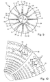
- FIG. 9 shows by way of example a plurality of possible images 35 of the luminous surface 13 of the semiconductor light source 12, which are generated by the regions 34 on which the images 35 are drawn.
- the uppermost point is denoted by one of the letters A to D, which is an indication of the corner A to D of the luminous surface 13 which, in the case of the image 35 of the luminous surface 13 generated by the region 34, is the uppermost point of the luminous surface 13 Image 35 forms.
- the attachment optics 10 comprises a plurality of semiconductor light sources 12, for example in the form of a semiconductor light source array (not shown), the points of the luminous area associated with the individual regions 34 of the interface 16 can be defined as the outer corner points of the total luminous area of the entire semiconductor light source array.
- FIG. 10 shows exemplary images 35 in two selected areas 34 of the interface 16 in detail.
- the corner A in FIG. 10 indicated by a circle and the corner B by a filled dot.
- the corner of the image 35 labeled A represents the uppermost corner.
- the corner B identified by way of example and the further corners C and D (not marked) are located in the images generated by the region 34' 35 of the luminous surface 13 always below the corner A or at most at the same height with the corner A.
- the corner B assigned area 34 '' is marked with B corner of the image 35, the top corner, the corner A and the other corners C and D (not marked) are always below the corner B at the images 35 of the luminous surface 13 produced by the region 34 "or at the same height as the corner B.
- FIG. 9 It can also be seen that the regions 34 are delimited or stepped by steps 40 relative to each other.
- the steps 40 may be provided to compensate for a shift of the images 35 generated by the regions 34 due to the distance between the corners A to D of the luminous surface 13.
- FIG. 11 shows a perspective rear view of the optical attachment 10, from which also the steps 40 between adjacent areas 34 can be seen.
- 34 steps 40 may be formed between all areas, wherein the height and configuration of the steps 40 may vary almost arbitrarily. It is also conceivable to round off the transitions between the areas 34 so that a continuous rear surface of the attachment optics 10 without kinks, edges and steps is formed.
- the light-dark boundary 42 produced by the optical attachment 10 according to the invention is substantially sharper than the light-dark boundary produced by the known auxiliary optics, while at the same time significantly improving the efficiency of the attachment optics 10.
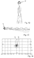
- FIG. 12 shows the attachment optics 10 with the corresponding beam path in a view of the attachment optics 10 in the vertical direction.
- FIG. 13 shows the attachment optics 10 with the corresponding beam path in a view in the horizontal direction from the side of the attachment optics 10.
- a through the beam paths of the FIGS. 12 and 13 generated light distribution on a arranged at a distance from the attachment optics 10 measuring screen shows FIG. 14 ,
- the light distribution has only a small horizontal scattering with an extension of about +/- 5 ° to the right and left of a vertical VV.
- a horizontal light-dark boundary 42 which is approximately at a horizontal HH or just below it, is sharply defined, at least in a range between +/- 3 °.
- the extension of the light bundle in the vertical direction is also relatively small and extends approximately from the horizontal HH downwards by approximately 5 °.
- the light distribution produced in this way represents a spotlight distribution that is in a spotlight module, for example, for improved illumination of the long range of a Low beam distribution, can be used.
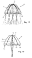
- FIGS. 15 to 17 show a further embodiment of the attachment optics 10 of the invention.
- curved surfaces 44 are formed.
- the curved surfaces 44 preferably have a longitudinal extent and are formed, for example, in the form of cylindrical or cylindrical segment-shaped lenses.
- the longitudinal axes of the curved surfaces, in particular the cylinder axes of cylindrical or cylindrical segment-shaped lenses, preferably extend (perpendicularly) transversely to the course of the light-dark boundary 42.
- FIG. 15 shows a plan view in the vertical direction on the attachment optics 10.
- the decoupled from the outcoupling surface 18 with the curved surfaces 44 light rays are scattered transversely to the extension of the longitudinal axis in the horizontal direction, which is based on the in the FIGS. 18 and 19 illustrated beam trajectories is illustrated.
- the curved surfaces 44 can be arranged either as an integral part of the decoupling surface 18 or as a separate optical element at a distance from the decoupling surface 18 in the beam path of the decoupled light beams.
- FIG. 17 shows a sectional view through the optical attachment 10 from FIG. 15 along the line XVII-XVII with an exemplary drawn beam path. So while the FIGS. 18 and 19 the horizontal scattering of passing through the optical attachment 10 light beams can be seen, shows the FIG. 17 a (hardly existing) vertical scattering of the passing light rays. In the vertical direction, the light passing through the attachment optics 10 is thus bundled relatively strongly. An upper side of the resulting partial light distribution can be used for Generation of the light-dark boundary 42 are used.
- FIG. 17 only shows the so-called second possible beam path according to FIG. 2 which impinges on the decoupling surface 18 via the light-injecting surface 14b through the direct-imaging lens 22 without total internal reflection at the interfaces 16.
- the curved surfaces 44 lead in a corresponding manner also in the first possible beam path according to FIG. 1 in that the light beams coupled into the optical attachment 10 via the lateral coupling-in surfaces 14 strike the decoupling surfaces 18 after a total reflection at the boundary surfaces 16 and are hardly scattered by the curved surfaces in the vertical direction, but rather are bundled.
- boundary surface 16 or the regions 34 with correspondingly configured facets in order to achieve a scattering of the light coupled out of the attachment optics 10.
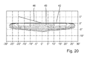
- the optical attachment 10 can be used in a light module 28 of a headlight 24 for generating a light distribution, as exemplified in FIG. 20 is shown.
- This light distribution is well suited for a fog light, a basic light distribution of a low beam headlight or for a turn-off spotlight.
- the light distribution is relatively widely scattered in the horizontal direction (about +/- 28 °) and has a sharp horizontal light-dark boundary 42 on its upper side. Even a region 43 with high light intensity in the center of the light distribution extends in the horizontal direction relatively wide (about +/- 10 °).
- the light distribution causes a wide illumination of the road ahead of the vehicle, especially in the area of the road edges.
- FIG. 20 When the light distribution off FIG. 20 represents a basic light distribution of a low-beam distribution, it can with a spot light distribution (see. FIG. 14 ) are superimposed.
- the spotlight distribution has only a relatively small horizontal extension (about +/- 4 °) and a highly concentrated central region 45 with high light intensity.
- the spotlight distribution when superposed with the basic light distribution, ensures good illumination of a long range of the low beam distribution immediately below the light-dark boundary 42.
- the optical attachment 10 can be rotated together with the light source 12 or the entire light module 28 by 15 ° about the optical axis 20.
- the inclined spotlight distribution which then results on a screen, with its inclined section 42 'of the light-dark boundary is in FIG. 22 shown.
- the from a superposition of the spotlight distribution FIG. 22 and the basic light distribution FIG. 20 resulting low beam distribution is in FIG. 23 represented, wherein in the Figures 22 and 23 shown light distributions are provided for left-hand traffic. In a low beam distribution for legal traffic in the FIG.
- a vertical light-dark boundary (not shown) can be generated, which then also integrates modularly into an overall system for generating a total light distribution, for example a light distribution of a partial high-beam or masked high-beam can be.
- the optical attachment 10 together with the semiconductor light source 12 and the entire light module 28 about axes of rotation which are arranged perpendicular to the optical axis 20, is pivotable.
- the intent optical system 10 according to the invention can also be used for the realization of dynamic lighting functions, since the rotation of the attachment optics 10 and the light module 28 is also possible during a journey.
- a modification of the attachment optics 10 according to the invention, in particular with regard to the configuration of the regions 34 of the interfaces 16, is not necessary for this purpose.
- the drive elements necessary for setting the dynamic light functions can act directly on the attachment optics 10 or the light module 28.
- a dynamic headlamp leveling can be realized, in which an adjustment of the light-dark boundary 42 to a pitch angle of the vehicle, ie to a longitudinal inclination of the vehicle is realized.
- a horizontal pivoting of the attachment optics 10 to a vertical axis to realize a dynamic cornering light, in which when passing through curves, the optical axis 20 is tracked in the direction of the curve.
- the light output surface 18 is not aligned transversely, but substantially parallel to the optical axis 20.
- the coupled into the optical attachment 10 light is reflected at an additional provided, obliquely to the optical axis 20 extending boundary surface 48 in the direction of the decoupling surface 18, preferably totally reflected.
- the further boundary surface 48 can redirect the light coupled into the optical attachment 10, if appropriate after reflection at the boundary surfaces 16, in such a way that a main light exit direction 30 of the light from the attachment optics 10 is at an angle to the optical axis 20, preferably approximately 90 °, is directed.
- the light can be coupled out at any other angles to the optical axis 20 of the attachment optics 10.
- the further boundary surface 48 may be formed such that the light is scattered or bundled after an exit of the light from the light output surface 18. In the in FIG. 24 In the embodiment shown, the further boundary surface 48 is slightly convex, so that the light is scattered slightly out of the light output surface 18. In a more concave formation of the further boundary surface 48, the light would be bundled after emerging from the light output surface 18. Such a configuration of the attachment optics 10 offers the possibility of being able to adapt the attachment optics 10 better to an available installation space.
- the optical attachment 10 it is possible for the optical attachment 10 to have at least one of the regions 34 of the interfaces 16 having steps 50.
- a step-shaped formation of at least one region 34 the distance of the region 34 to the semiconductor light source 12 can be changed, whereby the images of the luminous surface 13 can be increased or decreased.
- steps 50 it is also possible, for example, a zone 43, 45 of the greatest light intensity in the generated light distribution (cf. Figures 20 and 22 ) to move.
- the step-shaped formation may relate to only a single area 34 of the boundary surfaces 16, it may of course also affect several or all areas 34 of the interface 16.
- the invention has been described in such a way that the light-dark boundary is produced by means of the (totally) reflecting boundary surfaces 16.
- the coupling surfaces 14; 14a, 14b and / or the decoupling surfaces 18; 18a, 18b participate in the generation of the light-dark boundary.
- the coupling surfaces 14; 14a, 14b and / or the decoupling surfaces 18; 18a, 18b the light-dark boundary alone, i. generate without the cooperation of the interfaces 16. In this case, all the surfaces 16, 16 cooperating with the generation of the light-dark boundary would then have to be used.
- 14; 14a, 14b; 18; 18a, 18b be divided into areas, wherein an interaction of the area cooperating surfaces 16; 14; 14a, 14b; 18; 18a, 18b, characterized in that by the interaction of the areas of the surfaces a corner A; B; C or D of the light source 12 is the point which is highest in the light-dark boundary.
Abstract
Description
Die vorliegende Erfindung betrifft eine Vorsatzoptik aus einem transparenten Material zum Einsatz in einem Lichtmodul eines Kraftfahrzeugscheinwerfers. Die Vorsatzoptik ist derart ausgebildet, dass sie von mindestens einer Halbleiterlichtquelle ausgesandtes Licht zur Erzeugung einer vorgegebenen Lichtverteilung mit einer Helldunkelgrenze bündelt. Die Vorsatzoptik umfasst mindestens eine Lichteinkoppelfläche zum Einkoppeln zumindest eines Teils des von der mindestens einen Halbleiterlichtquelle ausgesandten Lichts, reflektierende Grenzflächen zur Reflexion zumindest eines Teils des eingekoppelten Lichts, und mindestens eine Lichtauskoppelfläche zum Auskoppeln zumindest eines Teils des in die Vorsatzoptik eingekoppelten Lichts, eventuell nach einer Reflexion an einer der mindestens einen reflektierenden Grenzflächen.The present invention relates to a front optics made of a transparent material for use in a light module of a motor vehicle headlight. The optical attachment is designed such that it bundles light emitted by at least one semiconductor light source to produce a predetermined light distribution with a light-dark boundary. The attachment optics comprises at least one light coupling surface for coupling at least part of the light emitted by the at least one semiconductor light source, reflecting interfaces for reflecting at least part of the injected light, and at least one light coupling surface for coupling at least part of the light coupled into the optical attachment, possibly after one Reflection at one of the at least one reflective interfaces.
Außerdem ist Gegenstand der Erfindung ein Lichtmodul eines Kraftfahrzeugscheinwerfers, wobei das Lichtmodul mindestens eine Halbleiterlichtquelle zum Aussenden von Licht und mindestens eine der mindestens einen Halbleiterlichtquelle zugeordnete Vorsatzoptik zur Bündelung des von der mindestens einen Halbleiterlichtquelle ausgesandten Lichts und zur Erzeugung einer vorgegebenen Lichtverteilung mit einer Helldunkelgrenze umfasst.In addition, the subject of the invention is a light module of a Motor vehicle headlamps, wherein the light module comprises at least one semiconductor light source for emitting light and at least one of the at least one semiconductor light source associated auxiliary optics for focusing the light emitted from the at least one semiconductor light source and for generating a predetermined light distribution with a light-dark boundary.
Lichtmodule eines Kraftfahrzeugscheinwerfers, die als Halbleiterlichtquellen ausgebildete Lichtquellen aufweisen, weisen bekanntermaßen Vorsatzoptiken der eingangs beschriebenen Art als Primäroptiken zur Bündelung des von den Lichtquellen ausgesandten Lichts auf. Die Halbleiterlichtquellen sind dabei bevorzugt als Leuchtdioden (LEDs) ausgebildet. Die Vorsatzoptiken sind in einer Hauptabstrahlrichtung der Halbleiterlichtquellen vor diesen angeordnet, so dass das von den Halbleiterlichtquellen ausgesandte Licht in die Vorsatzoptiken eingekoppelt wird. Die Vorsatzoptiken bestehen vorzugsweise aus einem transparenten Material, insbesondere Glas oder Kunststoff, und weisen an sich vorzugsweise trichterförmig erstreckenden seitlichen Grenzflächen reflektierende, insbesondere totalreflektierende Eigenschaften auf. Durch Brechung des Lichts an Lichteinkoppelflächen und/oder Lichtauskoppelflächen der Vorsatzoptik sowie durch eine Totalreflexion an den seitlichen Grenzflächen wird das von den Lichtquellen ausgesandte Licht in den Vorsatzoptiken gebündelt. Einer Vorsatzoptik können eine oder mehrere Halbleiterlichtquellen zugeordnet sein.Light modules of a motor vehicle headlight, which have light sources designed as semiconductor light sources, are known to have auxiliary optics of the type described above as primary optics for focusing the light emitted by the light sources. The semiconductor light sources are preferably designed as light-emitting diodes (LEDs). The attachment optics are arranged in front of them in a main emission direction of the semiconductor light sources, so that the light emitted by the semiconductor light sources is coupled into the attachment optics. The attachment optics preferably consist of a transparent material, in particular glass or plastic, and have reflective, in particular totally reflecting properties, on preferably laterally extending, funnel-shaped boundary surfaces. By refraction of the light at light input surfaces and / or light output surfaces of the optical attachment as well as by a total reflection at the lateral boundary surfaces, the light emitted by the light sources is focused in the attachment optics. An optical attachment can be assigned one or more semiconductor light sources.
Kraftfahrzeugscheinwerfer können, insbesondere wenn sie mit Halbleiterlichtquellen betrieben werden, modular aufgebaut sein, so dass in dem Scheinwerfer beispielsweise mehrere Lichtmodule angeordnet sind, die jeweils nur eine Teil-Lichtverteilung (z.B. Spotlicht zum Ausleuchten eines Fernbereichs einer Gesamt-Lichtverteilung oder eine Basis-Lichtverteilung zum Ausleuchten der seitlichen Bereiche der Gesamt-Lichtverteilung) einer gewünschten Gesamt-Lichtverteilung (z.B. eine abgeblendete Lichtverteilung, wie Abblendlicht, Nebellicht, Abbiegelicht o.ä.) erzeugen. Die Teil-Lichtverteilungen werden anschließend zur gewünschten vollständigen Lichtverteilung überlagert. Jede Teil-Lichtverteilung kann dabei durch ein separates Lichtmodul erzeugt werden. Der modulare Aufbau kann aber auch in einem einzigen Lichtmodul realisiert werden, wobei verschiedene Teile des Lichtmoduls (sog. Funktionsgruppen) unterschiedliche Teil-Lichtverteilungen bilden, die zur gewünschten Gesamt-Lichtverteilung überlagert werden. Eine Funktionsgruppe umfasst eine oder mehrere Halbleiterlichtquellen, die Licht aussenden, das von der ihnen zugeordneten Vorsatzoptik zu einer Teil-Lichtverteilung geformt wird.Automotive headlamps can, especially if they are operated with semiconductor light sources, be of modular design, so that in the headlight, for example, a plurality of light modules are arranged, each having only a partial light distribution (Eg spotlight for illuminating a long range of a total light distribution or a base light distribution for illuminating the lateral areas of the total light distribution) of a desired overall light distribution (eg a dimmed light distribution, such as low beam, fog light, cornering light, etc.) produce. The partial light distributions are then superimposed to the desired complete light distribution. Each partial light distribution can be generated by a separate light module. However, the modular structure can also be implemented in a single light module, wherein different parts of the light module (so-called functional groups) form different partial light distributions, which are superimposed to the desired overall light distribution. A functional group comprises one or more semiconductor light sources that emit light that is shaped by the associated optical attachment to a partial light distribution.
Aus dem Stand der Technik ist es ferner bekannt, dass zur Erzeugung einer Lichtverteilung mit einer Helldunkelgrenze (zum Beispiel bei Abblendlicht, Nebellicht, Abbiegelicht, etc.) zum Beispiel Licht abschattende Blenden oder Blendenanordnungen Anwendung finden, die in einem Strahlengang des von der Lichtquelle ausgesandten Lichts angeordnet sind. Zum Umschalten zwischen einer Lichtverteilung mit einer Helldunkelgrenze und einer Lichtverteilung ohne Helldunkelgrenze kann die Blende oder Blendenanordnung auch in den Strahlengang geschwenkt und aus diesem wieder heraus geschwenkt werden. Die Blende oder Blendenanordnung schattet, wenn sie im Strahlengang angeordnet ist, einen Teil des von der Primäroptik gebündelten Lichts ab, wobei eine Kante der Blende beziehungsweise der Blendenanordnung dabei die Helldunkelgrenze der Lichtverteilung bildet. Mit einer weiteren, abbildenden Optik (einer sog. Sekundäroptik), bspw. in Form einer Sammellinse, kann die abgeschattete Lichtverteilung mit der Helldunkelgrenze vor das Fahrzeug auf die Fahrbahn projiziert werden. Dabei wird eine Kante der Blende oder Blendenanordnung zur Erzeugung der Helldunkelgrenze auf der Fahrbahn abgebildet. Dies entspricht der Funktion eines bekannten Projektionsmoduls eines Scheinwerfers.From the prior art, it is also known that to produce a light distribution with a light-dark boundary (for example, low beam, fog light, cornering light, etc.), for example, light shading diaphragm or aperture arrangements apply, in a beam path of the light emitted from the light source Light are arranged. To switch between a light distribution with a light-dark boundary and a light distribution without a bright-dark boundary, the diaphragm or diaphragm arrangement can also be pivoted into the beam path and pivoted out of it again. The diaphragm or diaphragm arrangement, when it is arranged in the beam path, shadows a part of the light bundled by the primary optics, whereby one edge of the diaphragm or of the diaphragm arrangement forms the light-dark boundary of the light distribution. With a Further, imaging optics (a so-called secondary optics), for example in the form of a converging lens, the shaded light distribution with the light-dark border in front of the vehicle can be projected onto the road. In this case, an edge of the diaphragm or diaphragm arrangement for generating the light-dark boundary is imaged on the road. This corresponds to the function of a known projection module of a headlight.
Außer der beschriebenen Lichtverteilung mit einer horizontalen Helldunkelgrenze kann durch Abschatten eines Teils des gebündelten Lichts mittels entsprechend angeordneter und ausgerichteter Blenden oder Blendenanordnungen auch eine Lichtverteilung mit einer vertikalen Helldunkelgrenze erzeugt werden, wie sie bspw. bei einem sog. maskierten Fernlicht oder Teilfernlicht zum Einsatz kommt. Dabei wird die Fahrbahn vor dem Fahrzeug, wenn sich keine anderen Verkehrsteilnehmer vor dem Fahrzeug befinden, standardmäßig mit einer Fernlichtverteilung ausgeleuchtet. Durch geeignete Sensoren, bspw. in Form einer Kamera, werden Objekte in eine Bereich vor dem Fahrzeug detektiert. Dann werden abhängig von der Position der detektierten Objekte aus der Fernlichtverteilung gezielt lokale Bereiche abgeschattet, in denen sich detektierte Objekte befinden. Um den Bereich herum kann die Fahrbahn nach wie vor ausgeleuchtet werden.In addition to the described light distribution with a horizontal chiaroscuro border can be generated by shading a portion of the collimated light by means of appropriately arranged and aligned aperture or aperture arrangements, a light distribution with a vertical bright-dark boundary, as for example. In a so-called. Masked high beam or partial high beam is used. In this case, the road ahead of the vehicle, when there are no other road users in front of the vehicle, is standardly illuminated with a high beam distribution. By suitable sensors, for example in the form of a camera, objects are detected in an area in front of the vehicle. Then depending on the position of the detected objects from the high beam distribution targeted local areas are shadowed, in which there are detected objects. Around the area, the roadway can still be illuminated.
Bei der Erzeugung der Helldunkelgrenze mit Blenden ist nachteilig, dass die Blenden zusätzliche Bauteile darstellen, die teilweise durch entsprechende Stellelemente auch noch verstellt werden müssen, um eine gewünschte Variabilität der Lichtverteilung zu erzielen. Dies erhöht die Herstellungskosten bekannter Lichtmodule und Scheinwerfer. Außerdem wird durch die Blenden Licht abgeschattet, wobei das abgeschattete Licht keinen Beitrag mehr zur Erzeugung der Lichtverteilung leisten kann, sondern größtenteils im Scheinwerfer absorbiert wird. Der Wirkungsgrad des bekannten Lichtmoduls bzw. Scheinwerfers wird dadurch erheblich verschlechtert.When producing the light-dark boundary with diaphragms, it is disadvantageous that the diaphragms represent additional components which also have to be partially adjusted by corresponding adjusting elements in order to achieve a desired variability of the light distribution. This increases the manufacturing costs of known light modules and headlights. In addition, light is shaded by the apertures, with the shaded light no contribution can do more to produce the light distribution, but is largely absorbed in the headlight. The efficiency of the known light module or headlight is thereby significantly deteriorated.
Aus der
Aus der
Eine derart unscharfe Helldunkelgrenze ist zur Erzeugung einer Abblendlicht- oder Nebellichtverteilung mit horizontaler Helldunkelgrenze jedoch nur eingeschränkt nutzbar. Zur Erzeugung einer Lichtverteilung eines maskierten Fernlichts oder Teilfernlichts, insbesondere eines vertikalen Hell-Dunkel-Übergangs, wäre eine solche unscharfe Helldunkelgrenze gänzlich ungeeignet, da das Fernlicht zur sicheren Vermeidung einer Blendung der anderen vor dem Fahrzeug detektierten Verkehrsteilnehmer nicht nur an der Position eines detektierten Objekts, sondern auch seitlich davon in einem relativ großen Unschärfebereich abgeschattet werden müsste. Ziel des maskierten Fernlichts bzw. des Teilfernlichts ist es jedoch, lediglich einen möglichst kleinen Bereich des Fernlichts, in dem sich ein detektiertes Objekt befindet aus der Fernlichtverteilung auszunehmen und den Rest des Fernlichtbereichs auszuleuchten.However, such a fuzzy chiaroscuro limit can only be used to a limited extent in order to produce a low-beam or fog light distribution with a horizontal light-dark boundary. To generate a light distribution of a masked high beam or partial high beam, in particular a vertical bright-dark transition, such a blurred bright-dark border would be wholly inappropriate, since the high beam not only at the position of a detected object to safely avoid dazzling the other detected in front of the vehicle road users but should also be shaded sideways in a relatively large blur area. The aim of the masked high beam or the partial high beam, however, is to exclude only the smallest possible area of the high beam, in which a detected object is located from the high beam distribution and illuminate the rest of the high beam range.
Ausgehend von dem beschriebenen Stand der Technik liegt der vorliegenden Erfindung die Aufgabe zugrunde, eine kostengünstige und effizient arbeitende Vorsatzoptik zu schaffen, die ohne zusätzliche Blenden oder Blendenanordnungen eine Lichtverteilung mit einer scharfen Helldunkelgrenze erzeugen kann.Based on the described prior art, the present invention has the object, a To create cost effective and efficient working optics, which can produce a light distribution with a sharp light-dark border without additional screens or aperture arrangements.
Zur Lösung dieser Aufgabe wird ausgehend von der Vorsatzoptik der eingangs genannten Art vorgeschlagen, dass die reflektierenden Grenzflächen der Vorsatzoptik in mehrere Bereiche unterteilt sind, wobei jeder der Bereiche jeweils einem definierten Punkt einer Leuchtfläche der mindesten einen Halbleiterlichtquelle zugeordnet ist. Die den Bereichen zugeordneten Punkte umfassen mindestens zwei zueinander beabstandete Punkte der Leuchtfläche. Die Bereiche der reflektierenden Grenzflächen sind derart ausgebildet, dass jeder der Bereiche die Helldunkelgrenze der Lichtverteilung oder einen Teil davon erzeugt.To solve this problem, it is proposed on the basis of the optical attachment of the type mentioned that the reflective interfaces of the optical attachment are divided into several areas, each of the areas is assigned to a defined point of a luminous surface of at least one semiconductor light source. The points associated with the areas comprise at least two spaced-apart points of the luminous area. The regions of the reflective interfaces are formed such that each of the regions generates the light-dark boundary of the light distribution or a part thereof.
Die den Bereichen zugeordneten definierten Punkte sind vorzugsweise am Rand der Leuchtfläche angeordnet. Die Leuchtfläche selbst kann eine beliebige Form aufweisen, bspw. eine Kreis- oder Ellipsenfläche, oder die Form eines beliebigen Mehrecks, insbesondere eines Rechtecks oder eines Quadrats.The defined points associated with the areas are preferably arranged on the edge of the luminous area. The luminous surface itself can have any shape, for example a circular or elliptical surface, or the shape of any polygon, in particular a rectangle or a square.
Die reflektierenden Grenzflächen können durch Wahl eines geeigneten Materials der Vorsatzoptik und eine geeignete Ausgestaltung und Anordnung der Grenzflächen als totalreflektierende Flächen ausgebildet sein, so dass in einem ausreichend flach auf die Grenzflächen auftreffende Lichtstrahlen totalreflektiert werden. Alternativ können die Grenzflächen auch als einfach reflektierende Flächen ausgebildet sein, indem bspw. eine reflektierende Schicht außen auf die Grenzflächen aufgebracht wird. Einfach reflektierende Grenzflächen haben den Vorteil, dass eine Reflexion des austreffenden Lichts auch dann möglich ist, wenn die Bedingungen der Totalreflexion nicht eingehalten werden. Totalreflektierende Flächen haben den Vorteil einer größeren Effizient, da die Fresnel-Verluste des reflektierten Lichts geringer sind. Wenn nach folgend von reflektierenden Grenzflächen gesprochen wird, sind immer auch totalreflektierende Grenzflächen umfasst und umgekehrt, wenn nachfolgend von totalreflektierenden Grenzflächen gesprochen wird, sind immer auch einfach reflektierende Flächen umfasst.The reflective interfaces may be formed by selecting a suitable material of the optical attachment and a suitable design and arrangement of the interfaces as total reflecting surfaces, so that in a sufficiently flat on the boundary surfaces incident light beams are totally reflected. Alternatively, the interfaces may also be formed as simply reflecting surfaces, for example by applying a reflective layer to the outside of the interfaces. Simply reflecting interfaces have the advantage that a reflection of the incident light is possible even then if the conditions of total reflection are not met. Total reflecting surfaces have the advantage of greater efficiency, since the Fresnel losses of the reflected light are lower. When the following is said to be reflective interfaces, totally reflecting interfaces are always included, and vice versa, when subsequently referred to as totally reflecting interfaces, simply reflective surfaces are always included.
Die vorgesehenen Bereiche der reflektierenden Grenzflächen sind dabei bevorzugt derart ausgebildet, dass die durch sie erzeugten Abbilder der Leuchtfläche der mindesten einen Halbleiterlichtquelle eine gewünschte Lichtverteilung mit einer scharf abbildenden Helldunkelgrenze erzeugen. Die Ausgestaltung der Lichteinkoppelfläche und/oder der Lichtauskoppelfläche der Vorsatzoptik kann dabei unterstützend wirken, d.h. die hindurchtretenden Lichtstrahlen zusätzlich brechen, damit die durch die Lichtstrahlen erzeugten Abbilder die scharf abbildende Helldunkelgrenze erzeugen. Dabei wird vorteilhafterweise durch eine gezielte Ausgestaltung und Anordnung der Bereiche der Grenzflächen berücksichtigt, dass die der jeweiligen Vorsatzoptik zugeordnete mindestens eine Halbleiterlichtquelle eine ausgedehnte Lichtquelle ist, die eine gewisse Flächenerstreckung hat. Die erfindungsgemäße Vorsatzoptik kann eine Lichtverteilung mit einer besonders scharf abgebildeten Helldunkelgrenze erzeugen, ohne dass zusätzliche Hilfsmittel, bspw. im Strahlengang angeordnete Blenden oder Blendenanordnungen, zur Erzeugung der Helldunkelgrenze im Lichtmodul nötig wären.The intended regions of the reflective boundary surfaces are preferably designed such that the images of the luminous area of the at least one semiconductor light source generated by them produce a desired light distribution with a sharply imaging light-dark boundary. The design of the light incoupling surface and / or the light output surface of the attachment optics can thereby assist, i. In addition, the passing light rays break, so that the images produced by the light rays produce the sharp-imaging light-dark boundary. In this case, it is advantageously taken into account by a specific embodiment and arrangement of the regions of the boundary surfaces that the at least one semiconductor light source assigned to the respective intent optics is an extended light source which has a certain areal extent. The intent optical system according to the invention can produce a light distribution with a particularly sharply defined light-dark boundary without the need for additional aids, for example diaphragms or diaphragm arrangements arranged in the beam path, for generating the light-dark boundary in the light module.
Der vorliegenden Erfindung liegt die Idee zu Grunde, die Grenzflächen der Vorsatzoptik in mehrere Bereiche zu unterteilen, wobei jeder der Bereiche einem bestimmten Punkt der Leuchtfläche der mindestens einen Halbleiterlichtquelle zugeordnet ist. Die Bereiche sind jeweils derart ausgebildet, dass ein am dichtesten zu einer Helldunkelgrenze der Gesamt-Lichtverteilung liegender Punkt des durch den Grenzflächen-Bereich erzeugten Abbilds der Leuchtfläche der mindestens einen Halbleiterlichtquelle entweder auf der Helldunkelgrenze oder dicht unterhalb (bei einer horizontalen Helldunkelgrenze) oder dicht neben (bei einer vertikalen Helldunkelgrenze) der Helldunkelgrenze liegt, nach Möglichkeit nicht jenseits der Helldunkelgrenze, d.h. nicht in dem dunklen Bereich der Lichtverteilung, bspw. oberhalb einer horizontalen Helldunkelgrenze.The present invention is based on the idea of subdividing the interfaces of the optical attachment into several areas, each of the areas having a specific area Point of the luminous surface of the at least one semiconductor light source is assigned. The regions are each designed in such a way that a point of the area of the illuminated area of the at least one semiconductor light source produced by the interface region, which is closest to a light-dark boundary of the overall light distribution, is either at the light-dark boundary or closely below (at a horizontal light-dark boundary) or next to it (at a vertical light-dark boundary) of the light-dark boundary, if possible not beyond the light-dark boundary, ie not in the dark area of the light distribution, for example above a horizontal light-dark boundary.
Die komplette Gesamt-Lichtverteilung kann dabei von einer einzigen Vorsatzoptik erzeugt werden. Sie kann allerdings auch durch eine Anordnung mehrerer Vorsatzoptiken erzeugt werden, wobei sich die einzelnen von den Vorsatzoptiken erzeugten Teil-Lichtverteilungen zu der Gesamt-Lichtverteilung überlagern beziehungsweise ergänzen. Dabei können die Vorsatzoptiken, welche die Gesamt-Lichtverteilung erzeugen, Teil eines einzigen Lichtmoduls oder verschiedener Lichtmodule sein. Jeder Vorsatzoptik kann eine oder können mehrere Halbleiterlichtquellen zugeordnet sein. Außerdem ist es möglich, dass weitere, zum Beispiel in der Vorsatzoptik angeordnete optische Elemente, zur Erzeugung der Gesamt-Lichtverteilung des Lichtmoduls bzw. des Kraftfahrzeugscheinwerfers beitragen. Die Anzahl der Bereiche, in welche die Grenzflächen der Vorsatzoptik unterteilt sind, ist prinzipiell beliebig. Vorzugsweise ist die Anzahl der Bereiche ein Vielfaches i (z.B. i = 1...4) der Anzahl der Ecken der Leuchtfläche einer Halbleiterlichtquelle bzw. eines Arrays mehrerer neben- und/oder übereinander angeordneter Halbleiterlichtquellen.The complete overall light distribution can be generated by a single optical attachment. However, it can also be produced by an arrangement of several auxiliary optics, with the individual sub-light distributions generated by the auxiliary optics being superimposed or supplementing the overall light distribution. In this case, the auxiliary optics, which generate the overall light distribution, be part of a single light module or different light modules. Each attachment optics may be associated with one or more semiconductor light sources. It is also possible that further, for example arranged in the optical attachment optical elements, contribute to the generation of the total light distribution of the light module or the motor vehicle headlight. The number of areas into which the interfaces of the optical attachment are subdivided is in principle arbitrary. The number of regions is preferably a multiple i (eg i = 1... 4) of the number of corners of the luminous area of a semiconductor light source or an array of a plurality of semiconductor light sources arranged side by side and / or one above the other.
In einer bevorzugten Ausgestaltung der Vorsatzoptik erzeugen die Bereiche der reflektierenden Grenzflächen Abbilder der Leuchtfläche der mindestens einen Halbleiterlichtquelle, die vollständig unterhalb einer horizontalen Helldunkelgrenze oder allenfalls in einem Punkt auf der Helldunkelgrenze liegen. Ein definierter Punkt der Leuchtfläche, dem jeweils mindestens einer der Bereiche zugeordnet ist, entspricht dabei einer bestimmten Ecke der Leuchtfläche der Halbleiterlichtquelle. Dabei wird von einer viereckigen, bevorzugt quadratischen, Ausgestaltung der Leuchtfläche der Halbleiterlichtquelle ausgegangen. Eine runde Kontur der Leuchtfläche der Halbleiterlichtquelle wäre jedoch auch möglich, wobei in diesem Fall auf der runden Leuchtfläche beispielsweise vier (aber auch mehr oder weniger) gezielt ausgewählte Punkte, möglichst in symmetrischer Anordnung, definiert werden können und Bereiche der Grenzfläche der Vorsatzoptik diesen Punkten zugeordnet werden. Die Leuchtfläche kann aber auch als ein beliebiges Vieleck ausgestaltet sein, wobei die Bereiche der Grenzfläche ausgewählten (Eck-) Punkten zugeordnet sind.In a preferred embodiment of the attachment optics, the regions of the reflective boundary surfaces produce images of the luminous area of the at least one semiconductor light source which lie completely below a horizontal light-dark boundary or at most at a point on the light-dark boundary. A defined point of the luminous area, which is assigned to at least one of the areas, corresponds to a specific corner of the luminous area of the semiconductor light source. It is assumed that a square, preferably square, configuration of the luminous surface of the semiconductor light source. However, a round contour of the luminous surface of the semiconductor light source would also be possible, in which case four (but also more or less) selectively selected points, if possible in a symmetrical arrangement, can be defined on the round luminous area and areas of the interface of the optical attachment can be assigned to these points become. However, the luminous area can also be designed as an arbitrary polygon, wherein the areas of the interface are assigned to selected (corner) points.
Vorteilhafterweise erzeugt jeder der einem definierten Punkt der Leuchtfläche zugeordneten Bereiche auf einem in einem Abstand zu der Vorsatzoptik angeordneten Messschirm Abbilder der Leuchtfläche, wobei für alle Bereiche gilt, dass bei einer Erzeugung einer horizontalen Helldunkelgrenze der einem bestimmten Bereich zugeordnete definierte Punkt der Leuchtfläche den obersten Punkt des von dem Bereich erzeugten Abbildes der Leuchtfläche bildet. Der durch die Abbildung des definierten Punkts der Leuchtfläche erzeugte oberste Punkt des Abbilds liegt dicht unterhalb oder sogar auf der Helldunkelgrenze. Bei einer Erzeugung einer vertikalen Helldunkelgrenze bildet der einem bestimmten Bereich zugeordnete definierte Punkt der Leuchtfläche dementsprechend den von dem ausgeleuchteten Teil der Helldunkelgrenze kommend seitlich am dichtesten zur Helldunkelgrenze angeordneten Punkt des von dem Bereich erzeugten Abbildes der Leuchtfläche. Der durch die Abbildung des definierten Punkts der Leuchtfläche erzeugte am dichtesten bei der Helldunkelgrenze liegende Punkt des Abbilds liegt auf dem ausgeleuchteten Teil der Lichtverteilung dicht neben oder sogar auf der Helldunkelgrenze. Mit anderen Worten gilt ein bestimmter Bereich der Grenzfläche als einem bestimmten Punkt der Leuchtfläche zugeordnet, wenn - für eine horizontale Helldunkelgrenze - ein Abbild des Punkts auf einem in einem Abstand zu der Vorsatzoptik angeordneten Messschirm den höchsten Punkt des resultierenden Abbilds der Leuchtfläche bildet.Advantageously, each of the regions assigned to a defined point of the luminous area produces images of the luminous area on a measuring screen arranged at a distance from the optical attachment, wherein for all regions, when a horizontal bright-dark boundary is generated, the defined point of the luminous area assigned to a specific area is the uppermost point of the image generated by the area of the luminous surface forms. The uppermost point of the image produced by imaging the defined point of the luminous area is located just below or even at the light-dark boundary. When a vertical light-dark boundary is generated, the defined point assigned to a specific area forms the Luminous surface accordingly coming from the illuminated part of the light-dark boundary laterally closest to the light-dark boundary point of the generated image of the area of the luminous area. The point of the image produced closest to the light-dark boundary by the image of the defined point of the luminous area lies close to or even at the light-dark boundary on the illuminated part of the light distribution. In other words, a certain area of the boundary surface is assigned to a specific point of the luminous area if, for a horizontal light-dark boundary, an image of the point on a measuring screen arranged at a distance from the attachment optics forms the highest point of the resulting image of the luminous area.
Dazu muss - bei einer horizontalen Helldunkelgrenze - jeder der einem bestimmten Punkt zugeordneten Bereiche der totalreflektierenden Grenzflächen derart ausgebildet, ausgerichtet und/oder angeordnet sein, dass der oberste Punkt der resultierenden Abbildung der Leuchtfläche genau auf beziehungsweise möglichst dicht unterhalb der Helldunkelgrenze liegt. Dadurch ergibt sich automatisch, dass Lichtstrahlen aus den anderen Ecken und Punkten der Leuchtfläche nach der Totalreflexion an dem Bereich, der dem bestimmten Punkt zugeordnet ist, alle unterhalb der Helldunkelgrenze liegen. In der so ausgebildeten Vorsatzoptik kann nahezu das gesamte in die Vorsatzoptik eingekoppelte Licht zur Erzeugung der gewünschten Lichtverteilung genutzt werden, da kein Licht abgeschattet wird, so dass die erfindungsgemäße Vorsatzoptik einen besonders guten Wirkungsgrad aufweist.For this purpose, with a horizontal chiaroscuro limit, each of the regions of the totally reflecting interfaces assigned to a certain point must be designed, aligned and / or arranged in such a way that the uppermost point of the resulting image of the luminous area lies exactly at or as close as possible to the light-dark boundary. This automatically results in that light rays from the other corners and points of the luminous area after total reflection at the area associated with the particular point are all below the light-dark boundary. In the optical attachment designed in this way, almost the entire light coupled into the optical attachment can be used to generate the desired light distribution, since no light is shadowed, so that the optical attachment according to the invention has a particularly good efficiency.
Bei einer möglichen Anwendung eines Halbleiterlichtquellen-Arrays, bestehend aus mehreren matrixartig neben- und übereinander angeordneten Halbleiterlichtquellen, sind die entsprechenden Punkte der Leuchtfläche vorzugsweise derart definiert, dass die jeweiligen äußeren Eckpunkte des gesamten Arrays als die den verschiedenen Bereichen der Grenzflächen zugeordneten Punkte definiert sind.In a possible application of a semiconductor light source array, consisting of several adjacent matrix and Semiconductor light sources arranged one above the other are preferably defined such that the respective outer corner points of the entire array are defined as the points assigned to the different regions of the interfaces.
Die erfindungsgemäße Vorsatzoptik ist vorzugsweise nicht rotationssymmetrisch ausgestaltet. Es wäre allerdings denkbar, dass die Vorsatzoptik als ein bezüglich der optischen Achse der Vorsatzoptik rotationssymmetrischer Körper ausgebildet. Die totalreflektierenden Grenzflächen haben dabei bevorzugt eine trichterförmige Anordnung, wobei sich der Durchmesser der Vorsatzoptik quer zur optischen Achse von den Lichteinkoppelflächen zu den Lichtauskoppelflächen hin vergrößert. Die Grenzflächen sind bevorzugt in acht Bereiche unterteilt, wobei jedem Eckpunkt einer viereckigen Leuchtfläche jeweils zwei der Grenzflächen-Bereiche zugeordnet sind. Die erfindungsgemäße Vorsatzoptik ist vorzugsweise nicht punktsymmetrisch ausgestaltet. Es wäre allerdings denkbar, dass die Bereiche der totalreflektierenden Grenzflächen vorzugsweise in einer senkrecht zur optischen Achse der Vorsatzoptik verlaufenden Ebene betrachtet punktsymmetrisch ausgebildet sind, so dass sich nach einer Drehung der Vorsatzoptik um 180° um die optische Achse wieder die ursprüngliche zu Beginn der Drehung vorliegende Ausgestaltung und Anordnung der Grenzflächen ergibt.The intent optical system according to the invention is preferably configured not rotationally symmetrical. However, it would be conceivable that the attachment optics formed as a respect to the optical axis of the attachment optics rotationally symmetrical body. The total reflecting interfaces preferably have a funnel-shaped arrangement, wherein the diameter of the optical attachment increases transversely to the optical axis of the light input surfaces to the light outcoupling surfaces. The boundary surfaces are preferably subdivided into eight areas, with each corner point of a quadrangular luminous area being assigned in each case two of the boundary area areas. The intent optical system according to the invention is preferably configured not point-symmetrical. It would, however, be conceivable that the regions of the totally reflecting boundary surfaces are preferably formed point-symmetrically in a plane perpendicular to the optical axis of the attachment optics, so that after rotation of the attachment optics by 180 ° around the optical axis, the original at the beginning of the rotation Design and arrangement of the interfaces results.
Ein Übergang zwischen den einzelnen Bereichen kann als Knick, Kante oder Stufe für das menschliche Auge sichtbar ausgebildet sein. Es ist aber auch denkbar, dass die Übergänge zwischen den verschiedenen Bereichen für das menschliche Auge kaum wahrnehmbar fließend, d.h. ohne sichtbare Knick, Kanten und Stufen, ausgebildet ist. Grenzlinien zwischen den Grenzflächenbereichen können beliebig geformt sein, bspw. zumindest teilweise linear oder hyperbelähnlich. Durch eine punktsymmetrische Ausgestaltung der Vorsatzoptik können jeweils zwei bezüglich der optischen Achse diagonal gegenüberliegende Grenzflächenbereiche dem gleichen Punkt der Leuchtfläche zugeordnet sein. Die Anzahl der Bereiche kann natürlich von acht Bereichen abweichen, um beispielsweise mit noch mehr definierten Bereichen besonders feiner unterteilte Abbilder der Leuchtfläche auf dem Messschirm und damit auch auf der Fahrbahn zu erreichen.A transition between the individual regions can be designed to be visible to the human eye as a kink, edge or step. However, it is also conceivable that the transitions between the various regions are hardly perceptibly fluent, ie without visible kinks, edges and steps. Boundary lines between the interface areas can be formed arbitrarily, for example, at least partially linear or hyperbolic. By a point-symmetrical configuration of the attachment optics, in each case two interface areas lying diagonally opposite one another with respect to the optical axis can be assigned to the same point of the luminous area. Of course, the number of areas can deviate from eight areas, in order to achieve, for example, even more defined areas of particularly fine subdivided images of the illuminated area on the screen and thus also on the roadway.
Bei der Ausgestaltung der erfindungsgemäßen Vorsatzoptik ist es möglich, dass die Bereiche der totalreflektierenden Grenzflächen durch Stufen zueinander abgegrenzt sind. Diese Stufen entstehen dadurch, dass die definierten Punkte der Leuchtfläche, die den einzelnen Bereichen der Grenzfläche zugeordnet sind, einen Abstand zueinander aufweisen und von einem Bereich zum nächsten Bereich eine Verschiebung des Abbildes hervorrufen. Die Leuchtfläche wird erfindungsgemäß nicht als idealisierte punktförmige Lichtquelle, sondern als Lichtquelle mit einer flächenmäßige Ausdehnung angenommen, wie sie in der Praxis gegeben ist. Die Stufen zwischen den einzelnen Grenzflächenbereichen könnten allerdings vermieden, beziehungsweise zumindest in ihrer Höhe gemindert werden, wenn man im Übergang zwischen zwei benachbarten bzw. aneinander grenzenden Bereichen geringfügig vom optimalen Ziel, die den Bereichen zugeordneten definierten Punkte der Leuchtfläche möglichst exakt an die Helldunkelgrenze zu legen, abweicht. Die definierten Punkte werden dann im Übergang zwischen zwei aneinander grenzenden Bereichen geringfügig unterhalb der horizontalen Helldunkelgrenze gelegt. Dies kann bspw. durch eine Verrundung des Übergangs zwischen zwei benachbarten Bereichen erreicht werden. Die Verrundungen verwischen die Helldunkelgrenze in einem gewissen Maße, was in manchen Anwendungen sogar wünschenswert sein kann, bspw. bei Abblendlicht oder Nebellicht. In jedem Fall bleibt bei der vorliegenden Erfindung die Helldunkelgrenze wesentlich schärfer als bei den bekannten Vorsatzoptiken, wie sie bspw. aus der
Des weiteren ist es auch möglich, die einzelnen Bereiche der Grenzflächen der Vorsatzoptik in unterschiedlichen Abständen zur Leuchtfläche der Halbleiterlichtquelle anzuordnen. Dadurch kann unter Umständen Bauraum besser genutzt werden und man hat lichttechnisch die Möglichkeit, je nach Bedarf verschieden große Abbilder der Leuchtfläche zu erzeugen. Große Abbilder eignen sich prinzipiell besser für eine homogene Vorfeldbeleuchtung, kleine Abbilder eher für Bereiche mit großer Reichweite.Furthermore, it is also possible to arrange the individual areas of the boundary surfaces of the optical attachment at different distances from the light area of the semiconductor light source. As a result, space can be used under certain circumstances and it has the lighting technology, the possibility to produce different sized images of the luminous area as needed. In principle, large images are better suited for a homogeneous apron lighting, small images are more suitable for areas with a long range.
Vorteilhaft ist auch, dass die totalreflektierenden Grenzflächen und/oder die Lichtauskoppelflächen der Vorsatzoptik derart ausgebildet sind, dass die Vorsatzoptik ein Lichtbündel - bei einer horizontalen Helldunkelgrenze - mit in horizontaler Richtung divergierenden und/oder - bei einer vertikalen Helldunkelgrenze - mit in vertikaler Richtung von der Helldunkelgrenze weg und zum ausgeleuchteten Bereich der Gesamt-Lichtverteilung hin gerichteten divergierenden Strahlen erzeugt. Dabei wird eine Flächenausdehnung der Lichtquelle berücksichtigt. Die Grenzflächen-Bereiche werden derart ausgebildet, ausgerichtet und/oder angeordnet dass die durch die Vorsatzoptik gebildete Teil-Lichtverteilung die divergierenden Lichtstrahlen erzeugt. Die so erzeugte Teil-Lichtverteilung kann einer Spotlichtverteilung mit beispielsweise einer horizontalen Erstreckung von ca. +/- 5° und einer vertikalen Erstreckung von ca. 5° entsprechen. Die Grenzflächen können allerdings auch derart ausgebildet, ausgerichtet und/oder angeordnet sein, dass die resultierende Teil-Lichtverteilung weiter gestreckt wird und beispielsweise sogar eine Grundlichtverteilung für Abblendlicht erzeugt, die auf einem in einem Abstand zu der Beleuchtungseinrichtung mit der erfindungsgemäßen Vorsatzoptik angeordneten, senkrechten Messschirm beispielsweise eine horizontale Erstreckung von ca. +/- 28° und eine vertikale Erstreckung von ca. 7° aufweist.It is also advantageous that the total reflecting interfaces and / or the light outcoupling surfaces of the attachment optics are designed such that the attachment optics a light beam - at a horizontal light-dark boundary - diverging in the horizontal direction and / or - at a vertical light-dark boundary - with in the vertical direction of the Bright-dark border away and directed to the illuminated area of the overall light distribution towards divergent rays generated. In this case, a surface area of the light source is taken into account. The interface regions are formed, aligned and / or arranged such that the partial light distribution formed by the optical attachment produces the diverging light rays. The partial light distribution produced in this way can correspond to a spotlight distribution with, for example, a horizontal extent of approximately +/- 5 ° and a vertical extent of approximately 5 °. However, the interfaces can also do so be formed, aligned and / or arranged that the resulting partial light distribution is further stretched and, for example, even generates a basic light distribution for low beam, which arranged on a at a distance to the illumination device with the optical attachment according to the invention, vertical screen, for example, a horizontal extension of approx +/- 28 ° and a vertical extent of about 7 °.
Nach der Einkopplung von Licht in die Vorsatzoptik über die Lichteinkoppelfläche, werden in der Vorsatzoptik prinzipiell zwei unterschiedliche Lichtbündel erzeugt, deren Lichtstrahlen auf unterschiedlichen Wegen zur Lichtauskoppelfläche gelangen. Ein erstes Lichtbündel wird insbesondere durch von der Halbleiterlichtquelle schräg ausgesandte und über in etwa vertikal (parallel zur optischen Achse der Vorsatzoptik) stehende Einkoppelflächen in die Vorsatzoptik eingekoppelte Lichtstrahlen gebildet. Diese Lichtstrahlen treffen nach der Einkopplung auf die Bereiche der totalreflektierenden Grenzflächen und werden dort mindestens einmal totalreflektiert und zur Lichtauskoppelfläche gelenkt. Ein zweites Lichtbündel wird von der Halbleiterlichtquelle in etwa parallel zur Hauptabstrahlrichtung ausgesandte Lichtstrahlen gebildet, die durch in etwa horizontal (senkrecht zur optischen Achse der Vorsatzoptik) angeordnete Einkoppelflächen in die Vorsatzoptik eingekoppelt werden und ohne eine Totalreflexion an den Grenzflächen zur Auskoppelfläche gelangen. Für dieses zweite Lichtbündel ist in der Vorsatzoptik bevorzugt eine direkt abbildende Linse vorgesehen, bspw. an den Lichteinkoppelflächen und/oder den Lichtauskoppelflächen, die das Licht ohne Reflexion an den Grenzflächen bündelt, insbesondere weitgehend kollimiert (parallelisiert).After the coupling of light into the optical attachment via the light incoupling surface, in principle two different light beams are generated in the optical attachment, the light beams reach the light output surface in different ways. A first light beam is formed, in particular, by light beams which are emitted obliquely by the semiconductor light source and are coupled into the attachment optics via the coupling surfaces that are approximately vertical (parallel to the optical axis of the attachment optics). After the coupling, these light beams strike the areas of the totally reflecting boundary surfaces and are totally reflected there at least once and directed to the light output surface. A second light beam is formed by the semiconductor light source in approximately parallel to the main emission direction emitted light beams, which are coupled by approximately horizontally (perpendicular to the optical axis of the optical attachment) arranged coupling surfaces in the optical attachment and reach a total reflection at the interfaces to the decoupling surface. For this second light beam, a directly imaging lens is preferably provided in the optical attachment, for example, at the light coupling surfaces and / or the light coupling surfaces, which bundles the light without reflection at the interfaces, in particular largely collimated (parallelized).
Auch dieses zweite Lichtbündel muss die gewünschte Helldunkelgrenze erzeugen. Deshalb wird die in der Vorsatzoptik ausgebildete Linse für im Wesentlichen parallel zur optischen Achse bzw. zur Hauptabstrahlrichtung ausgesandte Lichtstrahlen derart angeordnet und geformt, dass eine Kante der Leuchtfläche der mindestens einen Halbleiterlichtquelle als Helldunkelgrenze der resultierenden Lichtverteilung oder als ein Teil davon abgebildet wird. Dadurch kann dieses zweite Lichtbündel das durch Reflexion an den totalreflektierenden Grenzflächen erzeugte erste Lichtbündel bei der Erzeugung der Helldunkelgrenze ergänzen bzw. unterstützen. Da die so ausgestaltete Vorsatzoptik die Lichtstrahlen der beiden Lichtbündel unabhängig voneinander lenkt und formt, damit sich beide Lichtbündel zur gewünschten Teil-Lichtverteilung ergänzen, ist die Vorsatzoptik sehr kompakt aufgebaut und benötigt vorteilhafterweise wenig Bauraum.This second light beam must also produce the desired light-dark border. Therefore, the lens formed in the optical attachment is arranged and shaped for light beams emitted essentially parallel to the optical axis or to the main emission direction such that an edge of the luminous area of the at least one semiconductor light source is imaged as a light-dark boundary of the resulting light distribution or as a part thereof. As a result, this second light bundle can supplement or support the first light bundle generated by reflection at the totally reflecting boundary surfaces during the generation of the light-dark boundary. Since the intent optics designed in this way directs and shapes the light beams of the two light bundles independently of each other, so that both light bundles complement each other to the desired partial light distribution, the optical attachment is very compact and advantageously requires little installation space.
Ferner ist vorteilhaft, dass die Lichtauskoppelfläche der Vorsatzoptik gekrümmte Flächen, insbesondere Zylinderlinsen oder Zylinderlinsensegmente umfasst, deren Zylinderachse vorzugsweise quer zum Verlauf der Helldunkelgrenze verlaufen. Eine solche Ausbildung der Lichtauskoppelfläche ist dann vorteilhaft, wenn beispielsweise eine breite Streuung des Lichts, insbesondere in horizontaler Richtung, gewünscht ist. Dabei können die gekrümmten Flächen nicht nur divergierende (streuende) Strahlen, sondern auch konvergierende (bündelnde) Strahlen erzeugen. Konvergierende und divergierende Lichtstrahlen sind bspw. zur Erzeugung einer Nebellichtverteilung, einer Grundlichtverteilung eines Abblendlichts oder einer Abbiegelichtverteilung geeignet, jeweils um eine möglichst breite Lichtverteilung zu erreichen und dadurch die Sicht des Fahrers in den entsprechenden Fahrsituationen zu verbessern.Furthermore, it is advantageous that the light output surface of the attachment optics comprises curved surfaces, in particular cylindrical lenses or cylindrical lens segments, whose cylinder axis preferably extends transversely to the course of the light-dark boundary. Such a design of the light output surface is advantageous if, for example, a wide scattering of the light, in particular in the horizontal direction, is desired. In this case, the curved surfaces can not only generate diverging (scattering) rays, but also converging (bundling) rays. Converging and diverging light beams are suitable, for example, for generating a fog light distribution, a basic light distribution of a low beam or a cornering light distribution, in each case in order to achieve the widest possible light distribution and thereby to improve the driver's view in the corresponding driving situations.
Natürlich kann eine solche Streuung des Lichts alternativ auch durch eine entsprechende Ausgestaltung der Lichteinkoppelfläche, der totalreflektierenden Grenzfläche, und/oder der im Innern der Vorsatzoptik angeordneten Linse, also ohne entsprechende Ausgestaltung der Lichtauskoppelflächen, gestaltet werden. Zur Erlangung einer breiten Lichtverteilung ist es auch möglich, die totalreflektierende Grenzfläche mit entsprechend ausgebildeten Facetten auszugestalten, die das Licht bereits in der Vorsatzoptik entsprechend formen, so dass es nach dem Durchtritt durch die Lichtauskoppelflächen gestreut ist. Genauso ist es möglich, dass ein zusätzliches, separat gefertigtes optisches Element mit brechenden und/oder reflektierenden Eigenschaften beabstandet vor der Lichtauskoppelfläche angeordnet ist, um das ausgekoppelte Licht der Vorsatzoptik nach dem Austritt aus der Vorsatzoptik entsprechend zu formen.Of course, such a scattering of the light can alternatively also by a corresponding configuration of the light incoupling surface, the total reflecting interface, and / or arranged in the interior of the optical attachment lens, so without corresponding design of the light outcoupling surfaces are designed. To obtain a wide light distribution, it is also possible to design the totally reflecting interface with correspondingly formed facets, which form the light already in the optical attachment accordingly, so that it is scattered after passing through the light coupling-out surfaces. Likewise, it is possible that an additional, separately manufactured optical element with refractive and / or reflective properties is arranged in front of the light outcoupling surface in order to shape the decoupled light of the optical attachment after emerging from the optical attachment.
In einer weiteren Ausführungsform der Vorsatzoptik ist es möglich, dass die totalreflektierenden Grenzflächen mindestens eine schräg zu einer optischen Achse der Vorsatzoptik verlaufende Grenzfläche umfassen, die das durch die Vorsatzoptik hindurchtretende Licht auf die Lichtauskoppelfläche umlenkt, wobei eine Lichtaustrittsrichtung des Lichts aus der Vorsatzoptik in einem Winkel zur optischen Achse und damit zur Hauptaustrittsrichtung der Lichtstrahlen aus der mindestens einen Lichtquelle gerichtet ist. Das Licht kann an der schräg stehenden Grenzfläche ebenfalls durch Totalreflexion reflektiert werden und kann je nach Ausbildung der schräg stehenden Grenzfläche eine Streuung beziehungsweise eine Bündelung des Lichts erzeugen. So ist es möglich, dass das aus der Vorsatzoptik austretende Licht in einem beliebigen Winkel zur Hauptabstrahlrichtung der Halbleiterlichtquelle, bevorzugt um 90° geschwenkt, austreten kann. Eine solche Ausgestaltung könnte beispielsweise eine bessere Positionierung der Vorsatzoptik im Lichtmodul ermöglichen, wodurch vorteilhafterweise ein im Scheinwerfer vorgegebener Bauraum besser genutzt werden könnte.In a further embodiment of the attachment optics, it is possible for the total reflecting interfaces to comprise at least one interface running obliquely to an optical axis of the attachment optics, which deflects the light passing through the attachment optics onto the light extraction surface, wherein an exit direction of the light from the attachment optics is at an angle is directed to the optical axis and thus to the main exit direction of the light rays from the at least one light source. The light can also be reflected by total reflection at the inclined boundary surface and, depending on the design of the inclined boundary surface, can produce a scattering or bundling of the light. Thus, it is possible that the light emerging from the optical attachment at any angle to the main emission direction of the semiconductor light source, preferably pivoted by 90 °, can escape. Such an embodiment could allow, for example, a better positioning of the attachment optics in the light module, whereby advantageously a predetermined space in the headlight space could be better used.
Außerdem ist vorteilhaft, dass mindestens einer der Bereiche der totalreflektierenden Grenzflächen Stufen aufweist. Dadurch kann eine breitere Form der Vorsatzoptik erreicht werden, wobei die Vorsatzoptik zum Beispiel bündig in einen vorgegebenen Bauraum eingepasst werden kann. Durch die stufenförmige Ausbildung mindestens einer der Bereiche der Grenzflächen kann auch der Abstand der Bereiche der Grenzflächen zur Lichtquelle verändert werden, wodurch die Abbilder der Leuchtfläche wahlweise vergrößert beziehungsweise verkleinert werden können. Ferner kann dadurch eine Zone der größten Lichtstärke in der erzeugten Teil-Lichtverteilung gezielt verschoben werden. Die stufenförmige Ausbildung kann einzelne Abschnitte der totalreflektierenden Grenzflächen betreffen, sie kann natürlich auch eine gesamte Grenzfläche betreffen.In addition, it is advantageous that at least one of the regions of the totally reflecting boundary surfaces has steps. As a result, a wider shape of the attachment optics can be achieved, wherein the attachment optics, for example, can be fitted flush in a given installation space. Due to the step-shaped design of at least one of the areas of the interfaces, the distance of the areas of the interfaces to the light source can be changed, whereby the images of the luminous area can optionally be increased or decreased. Furthermore, a zone of maximum light intensity in the generated partial light distribution can thereby be selectively shifted. The step-shaped formation may concern individual sections of the totally reflecting interfaces, but of course it may also relate to an entire interface.
Bei einer Anwendung der Erfindung in einem Lichtmodul mit mehreren Vorsatzoptiken kann vorgesehen sein, dass mindestens eine der Vorsatzoptiken zur Erzeugung einer bezüglich einer Horizontalen um einen beliebigen Winkel α schrägen Helldunkelgrenze oder senkrechten Helldunkelgrenze (α = 90°) um den Winkel α um die optische Achse der Vorsatzoptik gedreht ist. Bevorzugt wird die Vorsatzoptik mit samt der Halbleiterlichtquelle gedreht damit die Zuordnung der Bereiche der totalreflektierenden Grenzflächen zu den definierten Punkten der Leuchtfläche der Halbleiterlichtquelle erhalten bleibt. Diese Möglichkeit kann besonders dann vorteilhaft angewandt werden, wenn die gewünschte Gesamt-Lichtverteilung durch Überlagerung mehrerer Teil-Lichtverteilungen erzeugt wird. Ein erstes Scheinwerfer-Modul mit einer ersten Vorsatzoptik kann beispielsweise einen horizontalen Abschnitt einer asymmetrischen Helldunkelgrenze erzeugen, und ein anderes Scheinwerfer-Modul mit einer um 15° gedrehten Vorsatzoptik kann den 15 Grad Anstieg der Helldunkelgrenze erzeugen. Die resultierende Lichtverteilung mit der asymmetrischen Helldunkelgrenze ist somit aus dem Licht von zwei Vorsatzoptiken zusammengesetzt und kann bspw. für eine Spotlichtverteilung als Teil einer Abblendlichtverteilung oder eine fertige Abblendlichtverteilung genutzt werden. Wenn die resultierende Lichtverteilung eine Spotlichtverteilung ist, könnte ein weiteres Modul eine Grundlichtverteilung erzeugen, so dass eine Überlagerung der Spotlichtverteilung und der Grundlichtverteilung die resultierende Gesamt-Abblendlichtverteilung erzeugt, welche die gesetzlichen Anforderungen erfüllt.In an application of the invention in a light module with a plurality of attachment optics can be provided that at least one of the attachment optics for generating a relative to a horizontal α by any angle α oblique light-dark boundary or vertical light-dark boundary (α = 90 °) by the angle α about the optical axis the attachment optics is turned. Preferably, the attachment optics together with the semiconductor light source is rotated so that the assignment of the regions of the totally reflecting boundary surfaces to the defined points of the luminous area of the semiconductor light source is maintained. This possibility can be used particularly advantageous if the desired overall light distribution by Overlay several sub-light distributions is generated. For example, a first headlamp module with a first intent optic may create a horizontal portion of an asymmetric chiaroscuro boundary, and another headlamp module with a 15 degree rotated intent optic may produce the 15 degree increase in the light-dark boundary. The resulting light distribution with the asymmetrical light-dark boundary is thus composed of the light of two optical head units and can be used, for example, for a spotlight distribution as part of a low beam distribution or a finished low beam distribution. If the resulting light distribution is a spotlight distribution, another module could generate a base light distribution such that a superposition of the spotlight distribution and the basic light distribution produces the resulting total low beam distribution that meets the legal requirements.
Natürlich kann bei einer Drehung der Vorsatzoptik um 90 Grad auch eine vertikale Helldunkelgrenze erzeugt werden, die ebenfalls modular in ein Gesamtsystem zur Erzeugung einer Gesamt-Lichtverteilung, bspw. in Form eines Teilfernlichts, integriert werden kann.Of course, with a rotation of the attachment optics by 90 degrees, a vertical bright-dark boundary can be generated, which can also be modularly integrated into an overall system for generating an overall light distribution, for example in the form of a partial high-beam.
Ergänzend oder alternativ hierzu ist besonders vorteilhaft, dass mindestens eine der Vorsatzoptiken vorzugsweise zusammen mit der dieser zugeordneten mindestens einen Halbleiterlichtquelle um eine Drehachse, die quer zur optischen Achse der Vorsatzoptik verläuft, verschwenkbar ist. Das bedeutet, dass die erfindungsgemäße Vorsatzoptik auch zur Realisierung von dynamischen Lichtfunktionen verwendet werden kann. Dabei müssen keinerlei Modifikationen an der erfindungsgemäßen Vorsatzoptik selbst vorgenommen werden. Die zum Einstellen der dynamischen Lichtfunktionen nötigen Antriebselemente können dabei direkt an der Vorsatzoptik angreifen. Durch ein Verschwenken der Vorsatzoptik während der Fahrt ist es möglich, eine einer Fahrsituation angepasste Lichtverteilung zu erzeugen. So kann beispielsweise durch ein vertikales Verschwenken der Vorsatzoptik um eine horizontale Achse eine dynamische Leuchtweitenregulierung realisiert werden, bei der eine Anpassung der Helldunkelgrenze an einen Nickwinkel des Fahrzeugs realisiert wird. Außerdem ist es möglich, durch ein horizontales Verschwenken der Vorsatzoptik um eine vertikale Achse ein dynamisches Kurvenlicht zu realisieren, bei dem bei einer Kurvenfahrt eine Hauptabstrahlrichtung bzw. die optische Achse der Vorsatzoptik in Richtung einer Kurveninnenseite verschenkt wird.Additionally or alternatively, it is particularly advantageous that at least one of the attachment optics is preferably pivotable together with the at least one semiconductor light source associated therewith about an axis of rotation that runs transversely to the optical axis of the attachment optics. This means that the intent optical system according to the invention can also be used for the realization of dynamic light functions. In this case, no modifications to the attachment optical system according to the invention itself must be made. The drive elements necessary for setting the dynamic light functions can thereby attack directly on the attachment optics. By pivoting the attachment optics while driving, it is possible to generate a light distribution adapted to a driving situation. Thus, for example, by a vertical pivoting of the attachment optics about a horizontal axis, a dynamic headlamp leveling can be realized, in which an adaptation of the bright-dark boundary is realized at a pitch angle of the vehicle. In addition, it is possible to realize by a horizontal pivoting of the attachment optics about a vertical axis, a dynamic cornering light, in which when cornering a main emission or the optical axis of the attachment optics is given away in the direction of a curve inside.
Da auch das zuvor beschriebene Drehen der Vorsatzoptik um die optische Achse auch während der Fahrt möglich ist, kann beispielsweise bei einer Autobahnfahrt der 15 Grad Anstieg einer asymmetrischen Helldunkelgrenze einer Abblendlichtverteilung während der Fahrt verringert werden, bspw. auf Null Grad verringert werden, so dass eine durchgehende horizontale Helldunkelgrenze entsteht, wie dies bspw. bei einer Autobahnlichtverteilung vorteilhaft ist. Ferner könnte die optische Achse der Vorsatzoptik zur Erhöhung der Reichweite der ausgesandten Lichtverteilung während einer Autobahnfahrt angehoben werden. In einer weiteren Anwendungsmöglichkeit ist es z.B. möglich, bei einem Wechsel von Rechtsverkehr auf Linksverkehr oder umgekehrt, den 15 Grad Anstieg der asymmetrischen Helldunkelgrenze einer Abblendlichtverteilung entsprechend umzustellen, indem die Vorsatzoptik um 30° um die optische Achse vor- beziehungsweise rückgedreht wird.Since the above-described rotation of the optical attachment to the optical axis is also possible while driving, for example, in a highway driving the 15 degree increase in asymmetric light-dark boundary of a low-beam distribution while driving can be reduced, for example, be reduced to zero degrees, so that a continuous horizontal chiaroscuro border arises, as is advantageous, for example, in a motorway light distribution. Further, the optical axis of the optical attachment could be increased to increase the range of the emitted light distribution during a highway ride. In another application, it is e.g. it is possible, when changing from right-hand traffic to left-hand traffic or vice versa, to change the 15-degree increase in the asymmetrical light-dark limit of a low-beam light distribution by rotating the optical head up / down by 30 ° around the optical axis.
Weitere Merkmale und Vorteile der Erfindung ergeben sich aus den abhängigen Ansprüchen, der Beschreibung und den beigefügten Figuren. Es versteht sich, dass die vorstehend genannten und die nachstehend noch zu erläuternden Merkmale nicht nur in der jeweils angegebenen Kombination, sondern auch in anderen Kombination oder in Alleinstellung einen wesentlichen Aspekt der Erfindung darstellen können. Die Figuren zeigen bevorzugt die Ausführungsbeispiele der Erfindung und werden in der nachfolgenden Beschreibung näher erläutert. Dabei zeigen:
- Fig. 1
bis 5 - verschiedene an sich aus dem Stand der Technik bekannte Lichtstrahlenverläufe in einer Vorsatzoptik;
- Fig. 6
- ein erfindungsgemäßes Lichtmodul eines Kraftfahrzeugscheinwerfers mit einer erfindungsgemäßen Vorsatzoptik;
- Fig. 7
- eine Leuchtfläche einer Leuchtdiode in einer Draufsicht entgegen einer Hauptaustrittsrichtung des von der Leuchtdiode ausgesandten Lichts betrachtet;
- Fig. 8 und 9
- die erfindungsgemäße Vorsatzoptik aus
Figur 6 in einer Draufsicht in einer Hauptabstrahlrichtung des von der Leuchtdiode ausgesandten Lichts betrachtet; - Fig. 10
- ein Teil eines Bereichs einer Grenzfläche der erfindungsgemäßen Vorsatzoptik aus
Figur 9 ; - Fig. 11
- die erfindungsgemäße Vorsatzoptik in einer perspektivischen Rückansicht;
- Fig. 12
- die erfindungsgemäße Vorsatzoptik mit einem beispielhaft eingezeichneten Strahlengang bei einer Sicht von oben;
- Fig. 13
- die erfindungsgemäße Vorsatzoptik mit einem beispielhaft eingezeichneten Strahlengang bei einer Sicht von der Seite;
- Fig. 14
- ein Beispiel für eine mit der erfindungsgemäßen Vorsatzoptik erzeugte Teil-Lichtverteilung auf einem Messschirm;
- Fig. 15
- eine Ausführungsform der erfindungsgemäßen Vorsatzoptik mit einer speziell ausgebildeten Lichtauskoppelfläche in einer Seitenansicht;
- Fig. 16
- die erfindungsgemäße Vorsatzoptik aus
Figur 15 in einer Draufsicht auf die Lichtauskoppelfläche; - Fig. 17
- eine Schnittansicht durch die Vorsatzoptik aus
Figur 15 mit beispielhaft eingezeichnetem Strahlengang; - Fig. 18
- die Vorsatzoptik aus
Figur 15 mit einem ersten möglichen Strahlengang des Lichts; - Fig. 19
- die Vorsatzoptik aus
Figur 15 mit einem zweiten möglichen Strahlengang des Lichts; - Fig. 20
- ein weiteres Beispiel für eine mit der erfindungsgemäßen Vorsatzoptik erzeugte Teil-Lichtverteilung auf einem Messschirm;
- Fig. 21
- eine erfindungsgemäße Vorsatzoptik nach einer Drehung um die optische Achse um einen Winkel α;
- Fig. 22
- ein Beispiel für eine mit der gedrehten Vorsatzoptik aus
Figur 21 erzeugte Teil-Lichtverteilung auf einem Messschirm; - Fig. 23
- eine durch eine Überlagerung der Teil-Lichtverteilungen
aus den Figuren 20 und22 erzeugte Gesamt-Lichtverteilung auf einem Messschirm; - Fig. 24
- eine erfindungsgemäße Vorsatzoptik gemäß einer weiteren Ausführungsform; und
- Fig. 25
- eine erfindungsgemäße Vorsatzoptik gemäß noch einer weiteren Ausführungsform.
- Fig. 1 to 5
- various light beam courses, known per se from the prior art, in an optical attachment;
- Fig. 6
- an inventive light module of a motor vehicle headlamp with an optical attachment according to the invention;
- Fig. 7
- a luminous surface of a light emitting diode in a plan view counter to a main exit direction of the light emitted by the light emitting diode viewed;
- 8 and 9
- the attachment optics of the invention
FIG. 6 considered in a plan view in a main radiation direction of the emitted light from the LED; - Fig. 10
- a part of a region of an interface of the optical attachment of the invention
FIG. 9 ; - Fig. 11
- the attachment optics according to the invention in a perspective rear view;
- Fig. 12
- the intent optical system according to the invention with an exemplary drawn beam path a view from above;
- Fig. 13
- the intent optical system according to the invention with an exemplary drawn beam path in a view from the side;
- Fig. 14
- an example of a partial light distribution generated with the inventive optical attachment on a measuring screen;
- Fig. 15
- an embodiment of the optical attachment according to the invention with a specially trained light output surface in a side view;
- Fig. 16
- the attachment optics of the invention
FIG. 15 in a plan view of the light output surface; - Fig. 17
- a sectional view through the attachment optics
FIG. 15 with exemplified drawn beam path; - Fig. 18
- the intent optics off
FIG. 15 with a first possible beam path of the light; - Fig. 19
- the intent optics off
FIG. 15 with a second possible beam path of the light; - Fig. 20
- a further example of a partial light distribution generated with the inventive optical attachment on a measuring screen;
- Fig. 21
- an optical attachment according to the invention after rotation about the optical axis by an angle α;
- Fig. 22
- an example of one with the turned Intent optics off
FIG. 21 generated partial light distribution on a measuring screen; - Fig. 23
- one by a superposition of the partial light distributions of the
Figures 20 and22 generated total light distribution on a screen; - Fig. 24
- a front lens according to the invention according to another embodiment; and
- Fig. 25
- a front lens according to the invention according to yet another embodiment.
Lichtmodule eines Kraftfahrzeugscheinwerfers oder einer Kraftfahrzeugleuchte, die mit Halbleiterlichtquellen betrieben werden, weisen häufig Vorsatzoptiken zur Bündelung des aus der Lichtquelle ausgesandten Lichts auf. Die Vorsatzoptiken bestehen aus einem transparenten Material, insbesondere Glas oder Kunststoff. Das zu bündelnde Licht der Lichtquelle wird zumindest teilweise in über mindestens eine Lichteinkoppelfläche in die Vorsatzoptik eingekoppelt, teilweise an seitlichen Grenzflächen der Vorsatzoptik totalreflektiert und das eingekoppelte Licht schließlich über mindestens eine Lichtauskoppelfläche wieder aus der Vorsatzoptik ausgekoppelt. Eine Bündelung des Lichts wird durch Brechung an den Lichteinkoppel- und/oder Lichtauskoppelflächen und/oder durch Totalreflexion an den seitlichen Grenzflächen erzielt. Einer Vorsatzoptik können eine oder auch mehrere Halbleiterlichtquellen zugeordnet sein.Light modules of a motor vehicle headlight or a motor vehicle light, which are operated with semiconductor light sources, often have attachment optics for focusing the light emitted from the light source. The attachment optics are made of a transparent material, especially glass or plastic. The light to be focused of the light source is at least partially coupled into at least one light input surface in the intent optics, partially reflected at lateral interfaces of the optical attachment total and finally decoupled the coupled light via at least one Lichtauskoppelfläche from the attachment optics. Bundling of the light is achieved by refraction at the Lichteinkoppel- and / or Lichtauskoppelflächen and / or by total reflection at the lateral interfaces. An optical attachment can be assigned one or more semiconductor light sources.
Die
Eine Hauptabstrahlrichtung des von der Leuchtdiode 12 ausgesandten Lichts verläuft im Wesentlichen parallel zu der optischen Achse 20 der Vorsatzoptik 10. Ein erster Strahlenverlauf des Lichts umfasst insbesondere schräg zur Hauptabstrahlrichtung ausgesandte Lichtstrahlen der Halbleiterlichtquelle 12, die an den seitlichen Lichteinkoppelfläche 14a in die Vorsatzoptik 10 eingekoppelt werden. Das an den Lichteinkoppelflächen 14a eingekoppelte Licht trifft anschließend auf Grenzflächen 16 der Vorsatzoptik 10, an der es durch Totalreflexion reflektiert und in Richtung von Auskoppelflächen 18a umgelenkt wird. Es ist bekannt, durch eine gezielte Ausgestaltung der Grenzflächen 16 als ganzes, beispielsweise durch ein Schrägstellen und/oder eine leichte Krümmung der Grenzflächen 16, kann das Licht gebündelt, vorzugsweise parallelisiert (kollimiert) werden. Anschließend wird das gebündelte Licht an den Lichtauskoppelflächen 18a der Vorsatzoptik 10 aus dieser ausgekoppelt. Dabei tritt das an den Grenzflächen 16 totalreflektierte Licht vorzugsweise an in einem Abstand zur optischen Achse 20 angeordneten Auskoppelflächen 18a aus der Vorsatzoptik aus. Sowohl beim Eintritt durch die Lichteinkoppelflächen 14a als auch beim Austritt durch die Lichtauskoppelflächen 18a kann das Licht gebrochen werden, was zusätzlich zur Bündelung des Lichts genutzt werden kann. Nach der Auskopplung aus der Vorsatzoptik 10 verlaufen die Lichtstrahlen im Wesentlichen parallel.A main emission direction of the light emitted by the light-emitting
Durch ein Verformen der Lichteinkoppelflächen 14, der Grenzflächen 16 und/oder der Lichtauskoppelflächen 18 kann der Strahlenverlauf durch die Vorsatzoptik 10 und damit die erzeugte Lichtverteilung beeinflusst werden. So sind in
In den
Das Lichtmodul 28 weist die Halbleiterlichtquelle 12 auf, der eine erfindungsgemäße Vorsatzoptik 10 zugeordnet ist. Das Lichtmodul 28 kann auch mehrere Halbleiterlichtquellen 12 mit jeweils einer zugeordneten Vorsatzoptik 10 aufweisen. Es ist auch möglich, dass mehrere Halbleiterlichtquellen 12 einer gemeinsamen Vorsatzoptik 10 zugeordnet sind.The
Ein wesentlicher Aspekt der vorliegenden Erfindung ist die Unterteilung der Grenzflächen 16 der Vorsatzoptik 10 in mehrere Bereiche 34, die jeweils definierten, zueinander beabstandeten Punkten der Leuchtfläche 13 zugeordnet sind. Diese sind vorzugsweise entlang der Außenkanten der Leuchtfläche 13 angeordnet. Besonders bevorzugt sind die Bereiche 34 den Eckpunkten A bis D der Leuchtfläche 13 der Halbleiterlichtquelle 12 zugeordnet. Bei einer runden oder ovalen Ausgestaltung der Leuchtfläche 13 können die den Bereichen 34 zugeordneten Punkte nach Belieben, vorzugsweise entlang der Außenkanten der Leuchtfläche 13, definiert werden. Besonders bevorzugt sind die definierten Punkte A bis D der Leuchtfläche 13 möglichst gleichmäßig zueinander beabstandet entlang der Außenkante angeordnet und sind jeweils zwei der Punkte A bis D bezüglich eines Schwerpunkts der Leuchtfläche 13 jeweils einander diagonal gegenüberliegend angeordnet.An essential aspect of the present invention is the subdivision of the boundary surfaces 16 of the
In dem dargestellten Beispiel ist die Grenzfläche 16 in acht Bereiche 34 unterteilt. Die Bereiche 34 sind konstruktionsbedingt teilweise durch lineare Grenzlinien 36 oder durch im Wesentlichen hyperbelförmige Grenzlinien 38 voneinander getrennt. Die Grenzfläche 16 kann dabei entlang der Grenzlinien 36 und 38 aufgetrennt sein. Jedem der abgrenzten Bereiche 34 ist eine bestimmte Ecke A bis D der Leuchtfläche 13 der Halbleiterlichtquelle 12 zugeordnet. Die den einzelnen Bereichen 34 jeweils zugeordnete Ecke A bis D der Leuchtfläche 13 ist durch Angabe der Bezeichnung der Ecke A bis D veranschaulicht. Die Form der Grenzlinie 36; 38 wird insbesondere durch die Bedingung bestimmt, dass aus einem Bereich 34 nur eine Ecke A; B; C oder D den höchsten Punkt des Abbildes bezüglich der Helldunkelgrenze erzeugt. Bei einer beispielhaften viereckigen Leuchtfläche der Lichtquelle 12 ist der Verlauf der Grenzlinien 36, 38 wie dargestellt. Wenn die Lichtquelle 12 eine andere Form hat, kann sich ein abweichender Verlauf der Grenzlinien 36, 38 ergeben.In the illustrated example, the
Die Zuordnung der Punkte A bis D der Leuchtfläche 13 zu den Grenzflächenbereichen 34 erfolgt nach folgendem Prinzip: Die Bereiche 34 erzeugen auf einem in einem Abstand zur Vorsatzoptik 10 angeordneten Messschirm Abbilder der Leuchtfläche 13 der Halbleiterlichtquelle 12. Die von den einzelnen Bereichen 34 erzeugten Abbilder sind in den
Aus
Die
In einer nicht dargestellten Ausführungsform ist es möglich, die Grenzfläche 16 beziehungsweise die Bereiche 34 mit entsprechend ausgebildeten Facetten auszugestalten, um so eine Streuung des aus der Vorsatzoptik 10 ausgekoppelten Lichts zu erreichen.In one embodiment, not shown, it is possible to design the
Die erfindungsgemäßen Vorsatzoptik 10 kann in einem Lichtmodul 28 eines Scheinwerfers 24 zur Erzeugung einer Lichtverteilung eingesetzt werden, wie sie beispielhaft in
Wenn die Lichtverteilung aus
Um einen bei Abblendlicht häufig gewünschten 15°-Anstieg eines auf der eigenen Fahrbahnseite angeordneten Abschnitts 42' (vgl.
Zur Erzeugung von Lichtverteilungen mit einer in einem beliebigen Winkel α angeordnete Helldunkelgrenze 42 ist es natürlich möglich, die Vorsatzoptik 10 in dem entsprechenden Winkel α um die optische Achse 20 zu drehen. So kann bei einer Drehung der Vorsatzoptik 10 um α = 90° beispielsweise auch eine vertikale Helldunkelgrenze (nicht dargestellt) erzeugt werden, die dann ebenfalls modular in ein Gesamtsystem zur Erzeugung einer Gesamt-Lichtverteilung, bspw. einer Lichtverteilung eines Teilfernlichts oder maskierten Fernlichts, integriert werden kann.To generate light distributions with a light-
In einer weiteren nicht dargestellten Ausführungsform ist es auch möglich, dass die Vorsatzoptik 10 zusammen mit der Halbleiterlichtquelle 12 bzw. das gesamte Lichtmodul 28 um Drehachsen, die senkrecht zur optischen Achse 20 angeordnet sind, verschwenkbar ist. Damit ist es möglich, dass die erfindungsgemäße Vorsatzoptik 10 auch zur Realisierung von dynamischen Lichtfunktionen eingesetzt werden kann, da das Verdrehen der Vorsatzoptik 10 bzw. des Lichtmoduls 28 auch während einer Fahrt möglich ist. Eine Modifikation der erfindungsgemäßen Vorsatzoptik 10, insbesondere bezüglich der Ausgestaltung der Bereiche 34 der Grenzflächen 16, ist dazu nicht nötig. Die zum Einstellen der dynamischen Lichtfunktionen nötigen Antriebselemente können dabei direkt an der Vorsatzoptik 10 bzw. dem Lichtmodul 28 angreifen. So kann beispielsweise durch ein vertikales Verschwenken der Vorsatzoptik 10 um eine horizontale Achse eine dynamische Leuchtweitenregulierung realisiert werden, bei der eine Anpassung der Helldunkelgrenze 42 an einen Nickwinkel des Fahrzeugs, also an eine Längsneigung des Fahrzeugs, realisiert wird. Außerdem ist es möglich, durch ein horizontales Verschwenken der Vorsatzoptik 10 um eine vertikale Achse ein dynamisches Kurvenlicht zu realisieren, bei dem beim Durchfahren von Kurven die optische Achse 20 in Kurvenrichtung nachgeführt wird.In another embodiment, not shown, it is also possible that the
In einer weiteren in
In einer weiteren in
Vorstehend ist die Erfindung so beschrieben, dass die Helldunkelgrenze mittels der (total)reflektierenden Grenzflächen 16 erzeugt wird. Prinzipiell ist es jedoch auch möglich, dass die Einkoppelflächen 14; 14a, 14b und/oder die Auskoppelflächen 18; 18a, 18b an der Erzeugung der Helldunkelgrenze mitwirken. Es wäre sogar denkbar, dass die Einkoppelflächen 14; 14a, 14b und/oder die Auskoppelflächen 18; 18a, 18b die Helldunkelgrenze alleine, d.h. ohne Mitwirkung der Grenzflächen 16 erzeugen. In diesem Fall müssten dann alle an der Erzeugung der Helldunkelgrenze mitwirkenden Flächen 16; 14; 14a, 14b; 18; 18a, 18b in Bereiche unterteilt sein, wobei ein Zusammenwirken der Bereich zusammenwirkender Flächen 16; 14; 14a, 14b; 18; 18a, 18b dadurch gekennzeichnet wäre, dass durch das Zusammenwirken der Bereiche der Flächen ein Eckpunkt A; B; C oder D der Lichtquelle 12 der Punkt ist, welcher am höchsten bezüglich der Helldunkelgrenze ist.In the foregoing, the invention has been described in such a way that the light-dark boundary is produced by means of the (totally) reflecting boundary surfaces 16. In principle, however, it is also possible that the coupling surfaces 14; 14a, 14b and / or the decoupling surfaces 18; 18a, 18b participate in the generation of the light-dark boundary. It would even be conceivable that the coupling surfaces 14; 14a, 14b and / or the decoupling surfaces 18; 18a, 18b the light-dark boundary alone, i. generate without the cooperation of the
Claims (15)
Applications Claiming Priority (1)
| Application Number | Priority Date | Filing Date | Title |
|---|---|---|---|
| DE201110078653 DE102011078653B4 (en) | 2011-07-05 | 2011-07-05 | Attachment optics for the bundling of emitted light of at least one semiconductor light source |
Publications (2)
| Publication Number | Publication Date |
|---|---|
| EP2543926A2 true EP2543926A2 (en) | 2013-01-09 |
| EP2543926A3 EP2543926A3 (en) | 2015-05-20 |
Family
ID=46458291
Family Applications (1)
| Application Number | Title | Priority Date | Filing Date |
|---|---|---|---|
| EP20120174888 Withdrawn EP2543926A3 (en) | 2011-07-05 | 2012-07-04 | Lens for bundling emitted light by means of a semiconductor light source (LED) |
Country Status (2)
| Country | Link |
|---|---|
| EP (1) | EP2543926A3 (en) |
| DE (1) | DE102011078653B4 (en) |
Cited By (5)
| Publication number | Priority date | Publication date | Assignee | Title |
|---|---|---|---|---|
| JP2014167879A (en) * | 2013-02-28 | 2014-09-11 | Koito Mfg Co Ltd | Vehicular lighting fixture |
| EP2818789A3 (en) * | 2013-04-17 | 2015-08-12 | Stanley Electric Co., Ltd. | Lighting unit for vehicle lamp |
| EP2837566B1 (en) * | 2013-08-13 | 2019-10-02 | Goodrich Lighting Systems GmbH | Exterior aircraft light unit and aircraft comprising the exterior aircraft light unit |
| WO2020064259A1 (en) * | 2018-09-28 | 2020-04-02 | Lumileds Holding B.V. | Multi-focal collimating lens and bi-function headlight assembly |
| WO2023025512A1 (en) * | 2021-08-25 | 2023-03-02 | Bayerische Motoren Werke Aktiengesellschaft | Headlight for a motor vehicle |
Families Citing this family (9)
| Publication number | Priority date | Publication date | Assignee | Title |
|---|---|---|---|---|
| DE102012104845A1 (en) * | 2012-06-05 | 2013-12-19 | Odelo Gmbh | LED for use as light source in e.g. lamp of motor car, has optic body partially enclosing LED chip and comprising light deflecting surfaces through which light is radiated from LED chip into body based on predetermined light distribution |
| US9156395B2 (en) | 2013-01-08 | 2015-10-13 | Ford Global Technologies, Llc | Low profile highly efficient vehicular LED modules and headlamps |
| US9476557B2 (en) | 2013-01-08 | 2016-10-25 | Ford Global Technologies, Llc | Low profile highly efficient vehicular LED modules and headlamps |
| DE102013108801B4 (en) * | 2013-08-14 | 2015-10-01 | Sick Ag | Camera with a lighting device for generating a lighting field |
| DE102015119718A1 (en) * | 2014-11-24 | 2016-05-25 | Ford Global Technologies, Llc | High-efficiency vehicle LED modules and low-profile headlamps |
| DE102016118152A1 (en) | 2016-09-26 | 2018-03-29 | Automotive Lighting Reutlingen Gmbh | Light module for a motor vehicle headlight |
| DE102017220488B4 (en) | 2016-11-24 | 2023-02-16 | Wuhan Tongchang Automotive Lighting Co., Ltd. | headlights for vehicles |
| DE102020111617A1 (en) * | 2020-04-29 | 2021-11-04 | Trilux Gmbh & Co. Kg | Optical body, light module and light system |
| DE102021124722A1 (en) | 2021-09-24 | 2023-03-30 | Bartenbach Holding Gmbh | radiator |
Citations (3)
| Publication number | Priority date | Publication date | Assignee | Title |
|---|---|---|---|---|
| DE10310263A1 (en) | 2002-10-24 | 2004-05-13 | Daimlerchrysler Ag | LED floodlight for asymmetrical illumination |
| DE10312364A1 (en) | 2003-03-20 | 2005-01-27 | Daimlerchrysler Ag | Motor vehicle headlamp with enhanced light dark boundary on the road has light diode source with ovoid central region and two parabolic reflectors |
| DE102008061619A1 (en) | 2007-12-12 | 2009-06-25 | Koito Manufacturing Co., Ltd. | vehicle light |
Family Cites Families (9)
| Publication number | Priority date | Publication date | Assignee | Title |
|---|---|---|---|---|
| ATE383544T1 (en) * | 2004-05-14 | 2008-01-15 | Fiat Ricerche | UNIT FOR PROJECTING A BEAM OF LIGHTS, AN OPTICAL DEVICE FOR THE UNIT, AND VEHICLE FRONT LIGHT DEVICE |
| US8631787B2 (en) * | 2005-07-28 | 2014-01-21 | Light Prescriptions Innovators, Llc | Multi-junction solar cells with a homogenizer system and coupled non-imaging light concentrator |
| US7837349B2 (en) * | 2007-06-15 | 2010-11-23 | Visteon Global Technologies, Inc. | Near field lens |
| DE102008013603B4 (en) * | 2008-03-11 | 2017-06-22 | Automotive Lighting Reutlingen Gmbh | Light module for a lighting device |
| JP5070129B2 (en) * | 2008-05-22 | 2012-11-07 | 株式会社小糸製作所 | Lighting fixtures for vehicles |
| JP5179328B2 (en) * | 2008-11-20 | 2013-04-10 | 株式会社小糸製作所 | Lighting fixtures for vehicles |
| JP5369359B2 (en) * | 2009-04-13 | 2013-12-18 | スタンレー電気株式会社 | Lamp |
| DE102009035544B4 (en) * | 2009-07-31 | 2019-10-24 | Volkswagen Ag | Headlamp in a motor vehicle with multiple semiconductor light sources |
| JP5475395B2 (en) * | 2009-10-23 | 2014-04-16 | スタンレー電気株式会社 | Vehicle lighting |
-
2011
- 2011-07-05 DE DE201110078653 patent/DE102011078653B4/en active Active
-
2012
- 2012-07-04 EP EP20120174888 patent/EP2543926A3/en not_active Withdrawn
Patent Citations (3)
| Publication number | Priority date | Publication date | Assignee | Title |
|---|---|---|---|---|
| DE10310263A1 (en) | 2002-10-24 | 2004-05-13 | Daimlerchrysler Ag | LED floodlight for asymmetrical illumination |
| DE10312364A1 (en) | 2003-03-20 | 2005-01-27 | Daimlerchrysler Ag | Motor vehicle headlamp with enhanced light dark boundary on the road has light diode source with ovoid central region and two parabolic reflectors |
| DE102008061619A1 (en) | 2007-12-12 | 2009-06-25 | Koito Manufacturing Co., Ltd. | vehicle light |
Cited By (8)
| Publication number | Priority date | Publication date | Assignee | Title |
|---|---|---|---|---|
| JP2014167879A (en) * | 2013-02-28 | 2014-09-11 | Koito Mfg Co Ltd | Vehicular lighting fixture |
| EP2818789A3 (en) * | 2013-04-17 | 2015-08-12 | Stanley Electric Co., Ltd. | Lighting unit for vehicle lamp |
| EP2837566B1 (en) * | 2013-08-13 | 2019-10-02 | Goodrich Lighting Systems GmbH | Exterior aircraft light unit and aircraft comprising the exterior aircraft light unit |
| WO2020064259A1 (en) * | 2018-09-28 | 2020-04-02 | Lumileds Holding B.V. | Multi-focal collimating lens and bi-function headlight assembly |
| US10890307B2 (en) | 2018-09-28 | 2021-01-12 | Lumileds Llc | Multi-focal collimating lens and bi-function headlight assembly |
| CN113242948A (en) * | 2018-09-28 | 2021-08-10 | 亮锐有限责任公司 | Multi-focal collimating lens and dual function headlamp assembly |
| CN113242948B (en) * | 2018-09-28 | 2022-05-03 | 亮锐有限责任公司 | Multi-focal collimating lens and dual function headlamp assembly |
| WO2023025512A1 (en) * | 2021-08-25 | 2023-03-02 | Bayerische Motoren Werke Aktiengesellschaft | Headlight for a motor vehicle |
Also Published As
| Publication number | Publication date |
|---|---|
| EP2543926A3 (en) | 2015-05-20 |
| DE102011078653B4 (en) | 2013-12-12 |
| DE102011078653A1 (en) | 2013-01-10 |
Similar Documents
| Publication | Publication Date | Title |
|---|---|---|
| DE102011078653B4 (en) | Attachment optics for the bundling of emitted light of at least one semiconductor light source | |
| EP3343091B1 (en) | Light module for motor vehicle headlamps | |
| DE10009782B4 (en) | Lighting device of a vehicle | |
| EP3351849B1 (en) | Led module and lighting device for a motor vehicle with a plurality of such led modules | |
| EP2799761B1 (en) | Light module for a motor vehicle headlamp | |
| DE102009008631B4 (en) | Projection module for a motor vehicle headlight | |
| DE102005015007B4 (en) | vehicle light | |
| DE102009053581B3 (en) | Light module for a lighting device of a motor vehicle | |
| EP2742280B1 (en) | Led light-source module for a vehicle headlight | |
| EP2492580B1 (en) | Lighting device for installation in a motor vehicle | |
| EP2523022B1 (en) | Lighting module of a motor vehicle headlamp for creating a variable light distribution and motor vehicle headlamp with such a lighting module | |
| DE60302708T2 (en) | Car headlights according to the projection principle with a secondary light source | |
| DE102009010558B4 (en) | Light module for a headlight of a motor vehicle and motor vehicle headlight with such a light module | |
| DE102014205994B4 (en) | Light module with semiconductor light source and attachment optics and motor vehicle headlight with such a light module | |
| WO2011154470A1 (en) | Attachment optical unit composed of transparent material for concentrating light, lens array comprising at least one such attachment optical unit and light module comprising such a lens array | |
| DE102011077636A1 (en) | Light module for head lamp system of motor vehicle i.e. motor car, has sub modules separately controlled to generate set of strip-shaped segments of spot distribution, where strip-shaped segments are complement to spot distribution | |
| DE102006037422A1 (en) | vehicle light | |
| DE102009037698A1 (en) | Vehicle lighting unit and vehicle light | |
| WO2006102882A1 (en) | Motor vehicle headlight | |
| DE202010006097U1 (en) | Light module for a motor vehicle headlight | |
| DE102009035743A1 (en) | Light module for a motor vehicle headlight | |
| EP2863108B1 (en) | LED module of a motor vehicle headlamp | |
| DE102009022848B4 (en) | Headlamp assembly and headlamp system for a motor vehicle | |
| EP3301350B1 (en) | Light module for a motor vehicle headlamp | |
| EP3765781B1 (en) | Light module for motor vehicle headlight |
Legal Events
| Date | Code | Title | Description |
|---|---|---|---|
| PUAI | Public reference made under article 153(3) epc to a published international application that has entered the european phase |
Free format text: ORIGINAL CODE: 0009012 |
|
| AK | Designated contracting states |
Kind code of ref document: A2 Designated state(s): AL AT BE BG CH CY CZ DE DK EE ES FI FR GB GR HR HU IE IS IT LI LT LU LV MC MK MT NL NO PL PT RO RS SE SI SK SM TR |
|
| AX | Request for extension of the european patent |
Extension state: BA ME |
|
| PUAL | Search report despatched |
Free format text: ORIGINAL CODE: 0009013 |
|
| AK | Designated contracting states |
Kind code of ref document: A3 Designated state(s): AL AT BE BG CH CY CZ DE DK EE ES FI FR GB GR HR HU IE IS IT LI LT LU LV MC MK MT NL NO PL PT RO RS SE SI SK SM TR |
|
| AX | Request for extension of the european patent |
Extension state: BA ME |
|
| RIC1 | Information provided on ipc code assigned before grant |
Ipc: F21S 8/12 20060101AFI20150410BHEP Ipc: F21V 5/00 20150101ALI20150410BHEP Ipc: F21V 7/00 20060101ALI20150410BHEP Ipc: F21S 8/10 20060101ALI20150410BHEP |
|
| STAA | Information on the status of an ep patent application or granted ep patent |
Free format text: STATUS: THE APPLICATION IS DEEMED TO BE WITHDRAWN |
|
| 18D | Application deemed to be withdrawn |
Effective date: 20151121 |