EP2543880A2 - Solargeneratorvorrichtung mit Sonnenverfolgungsfunktion - Google Patents
Solargeneratorvorrichtung mit Sonnenverfolgungsfunktion Download PDFInfo
- Publication number
- EP2543880A2 EP2543880A2 EP11005988A EP11005988A EP2543880A2 EP 2543880 A2 EP2543880 A2 EP 2543880A2 EP 11005988 A EP11005988 A EP 11005988A EP 11005988 A EP11005988 A EP 11005988A EP 2543880 A2 EP2543880 A2 EP 2543880A2
- Authority
- EP
- European Patent Office
- Prior art keywords
- support structure
- solar generator
- module
- solar
- generator apparatus
- Prior art date
- Legal status (The legal status is an assumption and is not a legal conclusion. Google has not performed a legal analysis and makes no representation as to the accuracy of the status listed.)
- Withdrawn
Links
- 230000004048 modification Effects 0.000 description 3
- 238000012986 modification Methods 0.000 description 3
- 230000005540 biological transmission Effects 0.000 description 1
Images


Classifications
-
- H—ELECTRICITY
- H02—GENERATION; CONVERSION OR DISTRIBUTION OF ELECTRIC POWER
- H02S—GENERATION OF ELECTRIC POWER BY CONVERSION OF INFRARED RADIATION, VISIBLE LIGHT OR ULTRAVIOLET LIGHT, e.g. USING PHOTOVOLTAIC [PV] MODULES
- H02S20/00—Supporting structures for PV modules
- H02S20/20—Supporting structures directly fixed to an immovable object
- H02S20/22—Supporting structures directly fixed to an immovable object specially adapted for buildings
-
- F—MECHANICAL ENGINEERING; LIGHTING; HEATING; WEAPONS; BLASTING
- F24—HEATING; RANGES; VENTILATING
- F24S—SOLAR HEAT COLLECTORS; SOLAR HEAT SYSTEMS
- F24S25/00—Arrangement of stationary mountings or supports for solar heat collector modules
- F24S25/70—Arrangement of stationary mountings or supports for solar heat collector modules with means for adjusting the final position or orientation of supporting elements in relation to each other or to a mounting surface; with means for compensating mounting tolerances
-
- F—MECHANICAL ENGINEERING; LIGHTING; HEATING; WEAPONS; BLASTING
- F24—HEATING; RANGES; VENTILATING
- F24S—SOLAR HEAT COLLECTORS; SOLAR HEAT SYSTEMS
- F24S30/00—Arrangements for moving or orienting solar heat collector modules
- F24S30/40—Arrangements for moving or orienting solar heat collector modules for rotary movement
- F24S30/45—Arrangements for moving or orienting solar heat collector modules for rotary movement with two rotation axes
- F24S30/455—Horizontal primary axis
-
- F—MECHANICAL ENGINEERING; LIGHTING; HEATING; WEAPONS; BLASTING
- F24—HEATING; RANGES; VENTILATING
- F24S—SOLAR HEAT COLLECTORS; SOLAR HEAT SYSTEMS
- F24S30/00—Arrangements for moving or orienting solar heat collector modules
- F24S30/40—Arrangements for moving or orienting solar heat collector modules for rotary movement
- F24S30/48—Arrangements for moving or orienting solar heat collector modules for rotary movement with three or more rotation axes or with multiple degrees of freedom
-
- H—ELECTRICITY
- H02—GENERATION; CONVERSION OR DISTRIBUTION OF ELECTRIC POWER
- H02S—GENERATION OF ELECTRIC POWER BY CONVERSION OF INFRARED RADIATION, VISIBLE LIGHT OR ULTRAVIOLET LIGHT, e.g. USING PHOTOVOLTAIC [PV] MODULES
- H02S20/00—Supporting structures for PV modules
- H02S20/30—Supporting structures being movable or adjustable, e.g. for angle adjustment
- H02S20/32—Supporting structures being movable or adjustable, e.g. for angle adjustment specially adapted for solar tracking
-
- Y—GENERAL TAGGING OF NEW TECHNOLOGICAL DEVELOPMENTS; GENERAL TAGGING OF CROSS-SECTIONAL TECHNOLOGIES SPANNING OVER SEVERAL SECTIONS OF THE IPC; TECHNICAL SUBJECTS COVERED BY FORMER USPC CROSS-REFERENCE ART COLLECTIONS [XRACs] AND DIGESTS
- Y02—TECHNOLOGIES OR APPLICATIONS FOR MITIGATION OR ADAPTATION AGAINST CLIMATE CHANGE
- Y02B—CLIMATE CHANGE MITIGATION TECHNOLOGIES RELATED TO BUILDINGS, e.g. HOUSING, HOUSE APPLIANCES OR RELATED END-USER APPLICATIONS
- Y02B10/00—Integration of renewable energy sources in buildings
- Y02B10/10—Photovoltaic [PV]
-
- Y—GENERAL TAGGING OF NEW TECHNOLOGICAL DEVELOPMENTS; GENERAL TAGGING OF CROSS-SECTIONAL TECHNOLOGIES SPANNING OVER SEVERAL SECTIONS OF THE IPC; TECHNICAL SUBJECTS COVERED BY FORMER USPC CROSS-REFERENCE ART COLLECTIONS [XRACs] AND DIGESTS
- Y02—TECHNOLOGIES OR APPLICATIONS FOR MITIGATION OR ADAPTATION AGAINST CLIMATE CHANGE
- Y02E—REDUCTION OF GREENHOUSE GAS [GHG] EMISSIONS, RELATED TO ENERGY GENERATION, TRANSMISSION OR DISTRIBUTION
- Y02E10/00—Energy generation through renewable energy sources
- Y02E10/40—Solar thermal energy, e.g. solar towers
- Y02E10/46—Conversion of thermal power into mechanical power, e.g. Rankine, Stirling or solar thermal engines
-
- Y—GENERAL TAGGING OF NEW TECHNOLOGICAL DEVELOPMENTS; GENERAL TAGGING OF CROSS-SECTIONAL TECHNOLOGIES SPANNING OVER SEVERAL SECTIONS OF THE IPC; TECHNICAL SUBJECTS COVERED BY FORMER USPC CROSS-REFERENCE ART COLLECTIONS [XRACs] AND DIGESTS
- Y02—TECHNOLOGIES OR APPLICATIONS FOR MITIGATION OR ADAPTATION AGAINST CLIMATE CHANGE
- Y02E—REDUCTION OF GREENHOUSE GAS [GHG] EMISSIONS, RELATED TO ENERGY GENERATION, TRANSMISSION OR DISTRIBUTION
- Y02E10/00—Energy generation through renewable energy sources
- Y02E10/40—Solar thermal energy, e.g. solar towers
- Y02E10/47—Mountings or tracking
-
- Y—GENERAL TAGGING OF NEW TECHNOLOGICAL DEVELOPMENTS; GENERAL TAGGING OF CROSS-SECTIONAL TECHNOLOGIES SPANNING OVER SEVERAL SECTIONS OF THE IPC; TECHNICAL SUBJECTS COVERED BY FORMER USPC CROSS-REFERENCE ART COLLECTIONS [XRACs] AND DIGESTS
- Y02—TECHNOLOGIES OR APPLICATIONS FOR MITIGATION OR ADAPTATION AGAINST CLIMATE CHANGE
- Y02E—REDUCTION OF GREENHOUSE GAS [GHG] EMISSIONS, RELATED TO ENERGY GENERATION, TRANSMISSION OR DISTRIBUTION
- Y02E10/00—Energy generation through renewable energy sources
- Y02E10/50—Photovoltaic [PV] energy
Definitions
- the invention relates to a solar generator apparatus with a sun-tracking function.
- a solar generator system is mounted on a building or at a fixed manner, and cannot be adjusted according to the azimuth angle of the sun, so that the received availability of the solar energy is significantly limited.
- An alternative conventional solar generator system is disposed on a movable support.
- the angle of this solar generator system can be adjusted with the change of the position of the sun, so that the received availability of the solar energy is increased.
- This solar generator system traces the sun by adjusting the angle according to the position of the sun in the sky, and is only suitable for the application with the small-scale generator, but is disadvantageous to the application with the large-scale generator.
- the conventional solar generator system still has to be improved.
- the invention provides a solar generator apparatus including a movable module, a first support structure, a connection structure, a second support structure, a carrying structure and a solar generator module.
- the first support structure has a first end connected to the movable module.
- the connection structure has a first end connected to the movable module.
- the second support structure has a first end connected to a second end of the connection structure.
- the carrying structure has a first end connected to a second end of the second support structure, and a second end connected to a second end of the first support structure.
- the solar generator module is disposed on the carrying structure.
- the movable module is rotatable about the second support structure, and a difference between lengths of the first support structure and the second support structure may be adjusted so that the solar generator module has a sun-tracking function.
- the solar generator apparatus with the sun-tracking function according to the invention is feasible to the application with either the small-scale generator or the large-scale generator, can be rotated and moved with multiple degrees of freedom, and can be adopted to various applications to effectively enhance the received availability of the solar energy.
- FIG. 1 is a pictorial view showing a solar generator apparatus according to a first embodiment of the invention.
- FIG. 2 is a pictorial view showing a solar generator apparatus according to a second embodiment of the invention.
- FIG. 3 is a pictorial view showing a solar generator apparatus according to a third embodiment of the invention.
- FIG. 4 is a cross-sectional view showing a carrying structure of the solar generator apparatus according to each of the second and third embodiments of the invention.
- FIG. 5 is a schematic illustration showing a movable module and a solar generator module according to the invention.
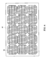
- FIG. 6 is a schematic plane view showing a solar panel according to the invention.
- connection includes, without limitation to, direct connection or indirect connection.
- FIG. 1 is a pictorial view showing a solar generator apparatus 1 according to a first embodiment of the invention.
- the solar generator apparatus 1 of this embodiment with the sun-tracking function includes a movable module 10, a first support structure 20, a connection structure 30, a second support structure 40, a carrying structure 50 and a solar generator module 60.
- the movable module 10 is a movable module providing multiple degrees of freedom of movements on the X-Z plane. The detailed structure thereof will be described later. At least one of the first support structure 20 and the second support structure 40 is retractable.
- the first support structure 20 and the second support structure 40 are disposed in a manner perpendicular to the floor or ground.
- the invention is not particularly restricted thereto.
- the first support structure 20 and the second support structure 40 may also be disposed on the floor or ground slantingly.
- the first support structure 20 has a first end 21 connected to the movable module 10.
- the first support structure 20 includes a lower column 23 and an upper column 24.
- the lower column 23 is connected to the connection structure 30.
- the upper column 24 is fit with the lower column 23, connected to the carrying structure 50, and retractable relative to the lower column 23.
- connection structure 30 has a first end 31 connected to the movable module 10.
- connection structure 30 is disposed in the horizontal direction.
- the invention is also not restricted thereto, and the connection structure 30 may also be disposed slantingly.
- the second support structure 40 has a first end 41 connected to a second end 32 of the connection structure 30, and is mounted to the fixed structure, such as the floor, ground or roof.
- the second support structure 40 includes a lower column 43 and an upper column 44.
- the lower column 43 is connected to the connection structure 30.
- the upper column 44 is fit with the lower column 43, connected to the carrying structure 50, and is retractable and rotatable relative to the lower column 43.
- the carrying structure 50 has a first end 51 connected to a second end 42 of the second support structure 40, and a second end 52 connected to a second end 22 of the first support structure 20.
- the solar generator module 60 is disposed on the carrying structure 50.
- screws can be provided to screw the solar generator module 60 to the carrying structure 50.
- the carrying structure 50 is rotatable relative to the first support structure 20 and the second support structure 40.
- the solar generator module 60 includes several solar panels 61. That is, the movable module 10 is rotatable about the second support structure 40, and the difference between the lengths of the first support structure 20 and the second support structure 40 can be manually or automatically adjusted so that the solar generator module 60 has the sun-tracking function.
- the carrying structure 50 is rotatably connected to the first support structure 20 and the second support structure 40.
- the solar generator module 60 can be rotated about a line, which connects the first end 51 of the carrying structure 50 to the second end 52 of the carrying structure 50 and serves as a center axis, so that the angle of the solar generator module 60 can be manually or automatically adjusted in a convenient manner.
- the solar generator apparatus 1 may further include a cable 70 having one end 71 connected to the solar generator module 60.
- the cable 70 is disposed in the second support structure 40, and may be connected to a charge controller or a grid tie inverter to store the electric energy or power the electric equipment.
- the second support structure 40 may be a hollow cylinder.
- FIG. 2 is a pictorial view showing a solar generator apparatus 1' according to a second embodiment of the invention. As shown in FIG. 2 , this embodiment is similar to the first embodiment except for the carrying structure 50'.
- the carrying structure 50 is a longitudinal structure, such as a hollow cylinder.
- the main structure of the carrying structure 50' is a frame body, so that the solar panel 61 of the solar generator module 60 can be conveniently fixed to the carrying structure 50'.
- FIG. 3 is a pictorial view showing a solar generator apparatus 1" according to a third embodiment of the invention. As shown in FIG. 3 , this embodiment is similar to the second embodiment except that the solar generator module 60' only contains one solar panel 61. This means that the solar generator apparatus 1/1' in the first/second embodiment is feasible to the high-power generator system, or even multiple solar generator apparatuses 1/1' may be arranged in an array, while the solar generator apparatus 1" of the third embodiment is feasible to the small-scale/low-power generator system.
- FIG. 4 is a cross-sectional view showing the carrying structure 50' of the solar generator apparatus according to each of the second and third embodiments of the invention.
- the carrying structure 50' includes a frame body 53, a first frame 54 and a second frame 55.
- the frame body 53 is, for example, a rectangular frame body.
- the first frame 54 connects the frame body 53 to the first support structure 20.
- the second frame 55 connects the frame body 53 to the second support structure 40.
- the frame body 53 still can be rotated relative to the first support structure 20 and the second support structure 40.
- first frame 54 may be fixed to the frame body 53 and pivotally connected to the first support structure 20, while the second frame 55 can be fixed to the frame body 53 and pivotally connected to the second support structure 40.
- first frame 54 may be pivotally connected to the frame body 53 and fixed to the first support structure 20, while the second frame 55 may be pivotally connected to the frame body 53 and fixed to the second support structure 40.
- FIG. 5 is a schematic illustration showing the movable module 10 and the solar generator module 60 according to the invention.
- the movable module 10 includes a motor 11 and a plurality of rollers 12.
- the rollers 12 are driven by the motor 11 to rotate, so that the movable module 10 is rotated about the second support structure 40, as shown in FIG. 1 .
- the motor 11 drives a pulley 14, disposed coaxially with the roller 12, through a driving pulley 13, a belt 15 or any other transmission element, and thus drives the roller 12 to rotate.
- the motor 11 may be powered by the solar generator module 60.
- FIG. 6 is a schematic plane view showing the solar panel 61 according to the invention. As shown in FIG. 6 , the solar panel 61 is constituted by multiple solar cells 62 connected in series or in parallel.
- the carrying structure 50 is disposed on the X-Y plane, so the solar generator module 60 can be rotated about a line on the X-Y plane.
- the movable module 10 is movable and the upper column 44 can be rotated relative to the lower column 43, so the solar generator module 60 can be rotated about the Y axis.
- the difference between the lengths of the first support structure 20 and the second support structure 40 can be adjusted, so the solar generator module 60 can be rotated about a line parallel to the Z axis. Consequently, the solar generator module 60 has the more flexible sun-tracking function.
- the solar generator apparatus with the sun-tracking function according to the invention is feasible to the application with either the small-scale generator or the large-scale generator, can be rotated and moved with multiple degrees of freedom, and can be adopted to various applications to effectively enhance the received availability of the solar energy.
Landscapes
- Engineering & Computer Science (AREA)
- Life Sciences & Earth Sciences (AREA)
- Sustainable Development (AREA)
- Chemical & Material Sciences (AREA)
- Physics & Mathematics (AREA)
- Sustainable Energy (AREA)
- Thermal Sciences (AREA)
- Combustion & Propulsion (AREA)
- Mechanical Engineering (AREA)
- General Engineering & Computer Science (AREA)
- Structural Engineering (AREA)
- Civil Engineering (AREA)
- Architecture (AREA)
- Photovoltaic Devices (AREA)
Applications Claiming Priority (1)
| Application Number | Priority Date | Filing Date | Title |
|---|---|---|---|
| US13/178,999 US20130008485A1 (en) | 2011-07-08 | 2011-07-08 | Solar generator apparatus with sun-tracking function |
Publications (2)
| Publication Number | Publication Date |
|---|---|
| EP2543880A2 true EP2543880A2 (de) | 2013-01-09 |
| EP2543880A3 EP2543880A3 (de) | 2013-09-04 |
Family
ID=44650795
Family Applications (1)
| Application Number | Title | Priority Date | Filing Date |
|---|---|---|---|
| EP11005988.8A Withdrawn EP2543880A3 (de) | 2011-07-08 | 2011-07-21 | Solargeneratorvorrichtung mit Sonnenverfolgungsfunktion |
Country Status (4)
| Country | Link |
|---|---|
| US (1) | US20130008485A1 (de) |
| EP (1) | EP2543880A3 (de) |
| JP (1) | JP2013021287A (de) |
| CN (2) | CN102868321A (de) |
Families Citing this family (16)
| Publication number | Priority date | Publication date | Assignee | Title |
|---|---|---|---|---|
| CN102662405A (zh) * | 2012-05-09 | 2012-09-12 | 北京北方奇德能源设备有限公司 | 一种太阳能自动翻转逐日平台装置 |
| USD718229S1 (en) * | 2012-06-27 | 2014-11-25 | Sunora Energy Solutions, LLC | Solar panel array |
| CN102954932A (zh) * | 2012-10-29 | 2013-03-06 | 北京华盛集智新能源科技有限公司 | 可调式全方位太阳电池室外测试系统 |
| CN102955120A (zh) * | 2012-10-29 | 2013-03-06 | 北京华盛集智新能源科技有限公司 | 可调式全方位太阳能电池室外测试系统 |
| CN102955119A (zh) * | 2012-10-29 | 2013-03-06 | 北京华盛集智新能源科技有限公司 | 可调式太阳电池室外测试系统 |
| JP6304596B2 (ja) * | 2014-07-29 | 2018-04-04 | 積水ハウス株式会社 | 太陽光発電装置 |
| JP6382015B2 (ja) * | 2014-07-31 | 2018-08-29 | 伊藤組土建株式会社 | 起伏地対応型太陽光パネル架台 |
| US11251745B2 (en) | 2014-12-12 | 2022-02-15 | Nevados Engineering, Inc. | Articulating joint solar panel array |
| JP6618270B2 (ja) * | 2015-04-28 | 2019-12-11 | 株式会社岡常歯車製作所 | 太陽光発電装置 |
| CN105305943B (zh) * | 2015-10-23 | 2017-06-16 | 黄山睿基新能源科技有限公司 | 一种斜单轴联动支架防基座下沉的固定安装结构 |
| DE102016015436B4 (de) * | 2016-12-23 | 2026-02-26 | Next2Sun Technology GmbH | Photovoltaik-Anlage mit bifazialen Photovoltaik-Modulen |
| CN107228499A (zh) * | 2017-07-28 | 2017-10-03 | 谢荟 | 一种太阳能电池板支架 |
| WO2019193996A1 (ja) * | 2018-04-05 | 2019-10-10 | 住友電気工業株式会社 | 太陽光発電装置 |
| KR102109859B1 (ko) * | 2018-07-04 | 2020-05-12 | 한국남동발전 주식회사 | 조립이 용이한 태양광 구조물 |
| KR102676714B1 (ko) * | 2021-07-09 | 2024-06-20 | (주)현명에너지 | Ai솔루션을 이용한 원격제어 시스템 |
| CN118554860B (zh) * | 2024-06-03 | 2025-05-02 | 江苏财茂新能源科技有限公司 | 一种安装在阳台栅栏的光伏板支架 |
Family Cites Families (20)
| Publication number | Priority date | Publication date | Assignee | Title |
|---|---|---|---|---|
| DE2966495D1 (en) * | 1979-07-24 | 1984-01-26 | Douglas E Wood | Support structure for a large dimension parabolic reflector and large dimension parabolic reflector |
| US4429178A (en) * | 1981-07-13 | 1984-01-31 | Acurex Solar Corporation | Solar tracking apparatus utilizing photovoltaic flat panels and method |
| US4476853A (en) * | 1982-09-28 | 1984-10-16 | Arbogast Clayton C | Solar energy recovery system |
| JPS6143711A (ja) * | 1984-08-08 | 1986-03-03 | Nec Corp | 追尾式太陽光発電装置 |
| US5244508A (en) * | 1992-04-02 | 1993-09-14 | The United States Of America As Represented By The Administrator Of The National Aeronautics And Space Administration | Self-deploying photovoltaic power system |
| JPH0888389A (ja) * | 1994-09-16 | 1996-04-02 | Hitachi Ltd | 太陽光利用発電ユニット |
| JP3906191B2 (ja) * | 2003-07-18 | 2007-04-18 | 信一郎 柏崎 | 太陽光発電装置用太陽追尾装置 |
| JP3639293B1 (ja) * | 2003-12-02 | 2005-04-20 | 英太郎 寺川 | グランド整備具 |
| DE102004018151A1 (de) * | 2004-04-08 | 2005-10-27 | Neff, Siegfried | Vorrichtung zur Ausrichtung eines Solarmoduls |
| ES2268938B1 (es) * | 2004-09-27 | 2008-03-01 | Fernando Garcia Fraile | Plataforma de seguimiento solar de ejes cruzados horizontales con contrapesos. |
| JP2010506415A (ja) * | 2006-10-09 | 2010-02-25 | カバニーリャス インヘニエロス,エセ.エレ. | 二軸ソーラートラッカー |
| JP5391523B2 (ja) * | 2007-03-22 | 2014-01-15 | 順一 三島 | 太陽エネルギ受恵体装置 |
| WO2010065941A2 (en) * | 2008-12-04 | 2010-06-10 | E-Cube Energy, Inc. | Systems and methods including features of synchronized movement across an array of solar collectors |
| JP2010147440A (ja) * | 2008-12-22 | 2010-07-01 | Tokyo Electric Power Co Inc:The | 情報表示装置および情報表示方法 |
| KR20100096669A (ko) * | 2009-02-25 | 2010-09-02 | 채준석 | 기울기를 갖는 태양광 발전기의 지지구조 |
| JP2010230604A (ja) * | 2009-03-30 | 2010-10-14 | Mizuho Information & Research Institute Inc | センサ装置及び太陽光発電装置 |
| KR101065055B1 (ko) * | 2009-04-20 | 2011-09-15 | 이형구 | 태양광 추적장치 |
| JP2011211025A (ja) * | 2010-03-30 | 2011-10-20 | Panasonic Corp | 車載用太陽光発電装置 |
| JP3163011U (ja) * | 2010-07-15 | 2010-09-24 | 鴻金達能源科技股▲ふん▼有限公司 | 太陽光発電装置 |
| CN201821298U (zh) * | 2010-10-11 | 2011-05-04 | 宁夏银星能源股份有限公司 | 光敏式单轴跟踪太阳能光伏发电装置 |
-
2011
- 2011-07-08 US US13/178,999 patent/US20130008485A1/en not_active Abandoned
- 2011-07-21 EP EP11005988.8A patent/EP2543880A3/de not_active Withdrawn
- 2011-07-22 CN CN2011102072797A patent/CN102868321A/zh active Pending
- 2011-07-22 CN CN2011202621906U patent/CN202145627U/zh not_active Expired - Fee Related
- 2011-11-14 JP JP2011248578A patent/JP2013021287A/ja active Pending
Non-Patent Citations (1)
| Title |
|---|
| None |
Also Published As
| Publication number | Publication date |
|---|---|
| EP2543880A3 (de) | 2013-09-04 |
| CN102868321A (zh) | 2013-01-09 |
| CN202145627U (zh) | 2012-02-15 |
| US20130008485A1 (en) | 2013-01-10 |
| JP2013021287A (ja) | 2013-01-31 |
Similar Documents
| Publication | Publication Date | Title |
|---|---|---|
| EP2543880A2 (de) | Solargeneratorvorrichtung mit Sonnenverfolgungsfunktion | |
| EP2543879B1 (de) | Solargeneratorvorrichtung mit seilzuggesteuerter Verfolgung | |
| EP2571063B1 (de) | Solargeneratorvorrichtung mit elastisch seilzuggesteuerter Verfolgung | |
| CN104247253B (zh) | 太阳光发电用跟踪装置 | |
| KR101593533B1 (ko) | 태양광 패널 지지 구조체 | |
| US20120227788A1 (en) | Low cost sun tracking pole mount for solar panels | |
| KR101264846B1 (ko) | 태양광 트랙커 및 태양광 발전장치 | |
| US20140223844A1 (en) | Building body with solar tracking device | |
| US8748732B2 (en) | Solar generator apparatus with suspending supports | |
| US20140209145A1 (en) | Photovoltaic device with debris cleaning assembly | |
| JP2010205764A (ja) | 追尾型太陽光発電装置 | |
| JP2016092969A (ja) | 角度可変形太陽光発電システム | |
| JP2010205762A (ja) | 追尾型太陽光発電装置 | |
| KR100917427B1 (ko) | 태양광 채광 장치 | |
| CN101662237B (zh) | 追日式太阳能储能装置及其方法 | |
| EP3560858B1 (de) | Fotovoltaischer behälter | |
| CN222525950U (zh) | 遮阳棚 | |
| CN205356250U (zh) | 光伏系统推杆联动装置 | |
| JP2015156779A (ja) | 太陽光パネル装置 | |
| KR102151850B1 (ko) | 모듈화된 태양광 추적 장치 | |
| CN108462460B (zh) | 一种光伏发电装置及供电系统 | |
| WO2022229625A1 (en) | A solar canopy | |
| US20140209144A1 (en) | Photovoltaic device with debris cleaning assembly | |
| JP5486358B2 (ja) | 船舶搭載用の太陽光発電システム | |
| TW201303237A (zh) | 具有追日功能之太陽能發電裝置 |
Legal Events
| Date | Code | Title | Description |
|---|---|---|---|
| PUAI | Public reference made under article 153(3) epc to a published international application that has entered the european phase |
Free format text: ORIGINAL CODE: 0009012 |
|
| AK | Designated contracting states |
Kind code of ref document: A2 Designated state(s): AL AT BE BG CH CY CZ DE DK EE ES FI FR GB GR HR HU IE IS IT LI LT LU LV MC MK MT NL NO PL PT RO RS SE SI SK SM TR |
|
| AX | Request for extension of the european patent |
Extension state: BA ME |
|
| PUAL | Search report despatched |
Free format text: ORIGINAL CODE: 0009013 |
|
| AK | Designated contracting states |
Kind code of ref document: A3 Designated state(s): AL AT BE BG CH CY CZ DE DK EE ES FI FR GB GR HR HU IE IS IT LI LT LU LV MC MK MT NL NO PL PT RO RS SE SI SK SM TR |
|
| AX | Request for extension of the european patent |
Extension state: BA ME |
|
| RIC1 | Information provided on ipc code assigned before grant |
Ipc: F03G 6/06 20060101AFI20130731BHEP Ipc: F24J 2/54 20060101ALI20130731BHEP |
|
| STAA | Information on the status of an ep patent application or granted ep patent |
Free format text: STATUS: THE APPLICATION IS DEEMED TO BE WITHDRAWN |
|
| 18D | Application deemed to be withdrawn |
Effective date: 20140201 |