EP2543603A1 - Powder removal device of medicine dispenser - Google Patents
Powder removal device of medicine dispenser Download PDFInfo
- Publication number
- EP2543603A1 EP2543603A1 EP11750558A EP11750558A EP2543603A1 EP 2543603 A1 EP2543603 A1 EP 2543603A1 EP 11750558 A EP11750558 A EP 11750558A EP 11750558 A EP11750558 A EP 11750558A EP 2543603 A1 EP2543603 A1 EP 2543603A1
- Authority
- EP
- European Patent Office
- Prior art keywords
- tablet
- receiving portion
- side wall
- powder
- opened
- Prior art date
- Legal status (The legal status is an assumption and is not a legal conclusion. Google has not performed a legal analysis and makes no representation as to the accuracy of the status listed.)
- Withdrawn
Links
Images








Classifications
-
- B—PERFORMING OPERATIONS; TRANSPORTING
- B08—CLEANING
- B08B—CLEANING IN GENERAL; PREVENTION OF FOULING IN GENERAL
- B08B7/00—Cleaning by methods not provided for in a single other subclass or a single group in this subclass
- B08B7/02—Cleaning by methods not provided for in a single other subclass or a single group in this subclass by distortion, beating, or vibration of the surface to be cleaned
-
- B—PERFORMING OPERATIONS; TRANSPORTING
- B65—CONVEYING; PACKING; STORING; HANDLING THIN OR FILAMENTARY MATERIAL
- B65B—MACHINES, APPARATUS OR DEVICES FOR, OR METHODS OF, PACKAGING ARTICLES OR MATERIALS; UNPACKING
- B65B39/00—Nozzles, funnels or guides for introducing articles or materials into containers or wrappers
- B65B39/001—Nozzles, funnels or guides for introducing articles or materials into containers or wrappers with flow cut-off means, e.g. valves
- B65B39/002—Pivoting plates
-
- B—PERFORMING OPERATIONS; TRANSPORTING
- B65—CONVEYING; PACKING; STORING; HANDLING THIN OR FILAMENTARY MATERIAL
- B65B—MACHINES, APPARATUS OR DEVICES FOR, OR METHODS OF, PACKAGING ARTICLES OR MATERIALS; UNPACKING
- B65B55/00—Preserving, protecting or purifying packages or package contents in association with packaging
-
- G—PHYSICS
- G07—CHECKING-DEVICES
- G07F—COIN-FREED OR LIKE APPARATUS
- G07F17/00—Coin-freed apparatus for hiring articles; Coin-freed facilities or services
- G07F17/0092—Coin-freed apparatus for hiring articles; Coin-freed facilities or services for assembling and dispensing of pharmaceutical articles
-
- B—PERFORMING OPERATIONS; TRANSPORTING
- B65—CONVEYING; PACKING; STORING; HANDLING THIN OR FILAMENTARY MATERIAL
- B65B—MACHINES, APPARATUS OR DEVICES FOR, OR METHODS OF, PACKAGING ARTICLES OR MATERIALS; UNPACKING
- B65B9/00—Enclosing successive articles, or quantities of material, e.g. liquids or semiliquids, in flat, folded, or tubular webs of flexible sheet material; Subdividing filled flexible tubes to form packages
- B65B9/06—Enclosing successive articles, or quantities of material, in a longitudinally-folded web, or in a web folded into a tube about the articles or quantities of material placed upon it
Definitions
- the present invention relates to a powder removal device of a medicine dispenser which dispenses tablets and prepares a medicine according to a prescription in hospitals, clinics, pharmacies, etc.
- a medicine dispenser which feeds required tablets from a tablet storing section having a plurality of tablet feeders to a tablet packaging section according to a prescription and packages the tablets one package at a time (see FIGS. 1 to 3 in Patent Document 1).
- a tablet storing section comprises the tablet feeders arranged in a shape of a shelf step and, similarly to the aforesaid medicine dispenser, required tablets are fed from the tablet storing section to a tablet packaging section according to a prescription and then is packaged one package at a time (see FIG. 6 in Patent Document 2).
- a tablet preparation section is provided between the tablet storing section and the tablet packaging section.
- the tablet preparation section keeps together tablets for one package and then feeds the tablets for one package to the tablet packaging section in a lump (see Paragraph [0051], lines 1 to 2, Paragraphs [0088] and [0101] to [0105] and FIGS. 11 to 15 in Patent Document 1).
- a tablet feeder wherein: a container for containing a large number of tablets houses a rotating rotor; receiving grooves (recesses) for receiving the tablets are formed in the rotor along an entire periphery of the rotor at equal spacing; along with the rotation of the rotor, the receiving groove receives the tablets in the container and moves the same in the rotation direction; and if the receiving groove faces to a discharge outlet, then the tablets in the receiving groove fall from the receiving groove to the discharge outlet one tablet at a time and thus the tablets are dispensed (see Patent Document 3).
- a tablet to be taken one time may be a half tablet (the half of a tablet).
- a tablet cut and divided into halves in advance be set to the dispensing device and then be dispensed.
- a tablet divider wherein a pair of belt conveyors sandwich a tablet and transfer the tablet downwardly and a rotary cutter divides the tablet in two halves during the transfer of the tablet ( see FIG. 1 in Patent Document 4).
- a tablet divider wherein a tablet is transferred to a tube and the tablet is stopped by a shutter and then divided in two halves by a cutter during the transfer of the tablet.
- the tablet piece of a lower half falls, while the tablet piece of an upper half is held on the cutter and then falls along with the retraction of the cutter ( see FIG. 6 in Patent Document 5).
- the process for powder particles described in the above-mentioned Patent Document 6 is irrelevant to stripping (removing) the adhesion powder particles from the tablet.
- the adhesion powder is fed from the tablet storing section to the tablet packaging section together with the tablet. That is, this does not prevent the adhesion powder particles from being contained in a package bag for tablets.
- the suction means or the air blast means are equipped in a tablet passage of a medicine dispenser to remove the adhesion powder from the tablet.
- this requires a large-scale suction or air blast mechanism and does not facilitate the treatment of the removed powder particles.
- the present invention removes the tablet-adhered powder by means of vibration in the tablet preparation section. Since the tablet preparation section temporarily keeps together the tablets, the adhesion powder of the tablet can be removed when vibration is applied to the tablets while the tablets are kept together.
- the present invention provides a powder removal device of a medicine dispenser, which feeds a tablet dispensed from a tablet storing section having a plurality of tablet feeders to a tablet packaging section and packages the tablet.
- the powder removal device is interposed between the tablet storing section and the tablet packaging section to remove a tablet-adhered powder.
- the powder removal device comprises: a top-opened receiving portion to which a tablet for one package is inputted from the tablet storing section, the top-opened receiving portion being provided between the tablet storing section and the tablet packaging section; means for vibrating the top-opened receiving portion; and means for opening and closing a bottom of the top-opened receiving portion.
- the bottom of the top-opened receiving portion has a gap, through which the tablet does not fall. The gap is opened by the opening and closing means to the extent of permitting the tablet to fall.
- the tablet in the top-opened receiving portion is subjected to vibrate due to the vibration of the top-opened receiving portion.
- the tablet bounces due to such vibration and thus the adhered powder is stripped therefrom.
- the stripped powder falls downwardly through the gap of the bottom.
- a powder collecting tray located below the gap in the bottom of the top-opened receiving portion receives the falling powder.
- the powder collecting tray is detachable.
- an inner surface of the receiving portion has a slip property by coating the inner surface with a slippage agent such as fluorine resin or sticking a sheet or plate piece with such a slippage agent coated so that the tablet and the powder stripped therefrom cannot adhere.
- the following various shapes may be considered: a rectangular boxlike shape, a cylindrical boxlike shape, an inverted conical boxlike shape, a boxlike shape of an inverted polygonal pyramid such as a boxlike shape of an inverted triangular pyramid or a boxlike shape of an inverted quadrangular pyramid, a boxlike shape of an inverted conical frustum, a boxlike shape of an inverted polygonal frustum such as a boxlike shape of an inverted triangular frustum or a boxlike shape of an inverted quadrangular frustum, or the like.
- the receiving portion may have any one of the above-described shapes, it is preferred that the bottom of the receiving portion has the gap and the tablet powder is stripped by means of vibration and the gap is opened when the powder is discharged. For this reason, "the gap through which the powder does not fall" is a gap for discharging the powder.
- the gap may not be formed in the bottom except when performing the dispensing operation (see an embodiment to be described below). Widening or narrowing the gap in the bottom can be achieved by moving a member constituting the bottom by means of the opening and closing means.
- the following configuration may be employed: a pair of opposing side wall plates constituting the top-opened receiving portion are disposed in a shape of an inverted triangle; both lower ends of the side wall plates have a gap through which the tablet does not fall; and at least one of the pair of the side wall plates is configured to be opened by the opening and closing means of the bottom of the top-opened receiving portion to the extent that the gap in the lower ends of both of the side wall plates permits the tablet to fall therethrough.
- being opened and closed of both of the side wall plates of the top-opened receiving portions to the extent of permitting the tablet to fall are done by swingably supporting the side wall plate at the upper end thereof and swinging the side wall plate.
- the aforementioned swing is done by the opening and closing means. Further, for example, the swing may be done by appropriately using an actuator plunger, a motor, means for swinging the side wall plate by a slide movement between the side wall plate and a cam with a cam surface for vertically moving the side wall plate (see an embodiment to be described below), or the like.
- a vibration motor wherein an eccentric part is provided in a rotating shaft of a motor coupled to the top-opened receiving portion; and means for bringing the top-opened receiving portion into slide contact with a plurality of prominences and depressions in sequence to vibrate the top-opened receiving portion (see an embodiment to be described below).
- the tablet preparation section includes a plurality of the top-opened receiving portions in view of keeping together a large number of tablets for one package and smoothly feeding the tablets for one package to the tablet packaging section in sequence.
- the configuration of the tablet preparation section the following configuration may be employed: a plurality of the top-opened receiving portions are provided in a rotator at equal interval around a rotation center of the rotator; an introducing inlet to the tablet packaging section opens in a portion of a rotation trajectory of each of the top-opened receiving portions; and an introducing inlet from the tablet storing section faces along a rotation direction of the rotator from the introducing inlet (see an embodiment to be described below).
- the following configuration may be employed: at least one of the pair of the opposing side wall plates of the top-opened receiving portion is swingably supported at an upper end thereof and is biased by a spring in a direction of contacting the other side wall plate; the swingable side wall plate is contacted with and separated from a prominence and depression around the rotator; and the swingable side wall plate is swung while maintaining the gap through which the tablet does not fall, thereby applying the vibration.
- the aspect that "the swingable side wall plate is swung while maintaining the gap through which the tablet does not fall” also includes that the lower ends of both of the side wall plates are in contact with each other during the vibration.
- the rotator in its entirety does not rattle due to the vibration.
- a fixed roller is provided for abutting the rotator to restrain the vibration.
- a cam roller may be provided in a swing shaft of the swingable side wall plate via an arm extending in a diametrical direction of the swing shaft and the cam roller may be contacted with and separated from the prominence and depression, thereby applying the vibration.
- the biasing force of the spring By adjusting the biasing force of the spring, the lower ends of both of the side wall plates may maintain the gap through which the tablet does not fall during the vibration.
- a stopper which engages the swingable side wall plate such that the swingable side wall plate maintains the gap, is preferably provided in the rotator.
- the stopper When the gap in the lower ends of both of the side wall plates is opened by the opening and closing means of the bottom of the top-opened receiving portion to the extent of permitting the tablet to fall, the stopper needs to permit such an action.
- the stopper is configured to release the engagement to the side wall plate. The release of the engagement may be done by a slide movement of a pawl on a cam to be described below.
- the above-described cam roller performs its operation by rolling on a cam surface of the cam provided around the rotator (see Reference numeral 82d in FIG. 13 in Patent Document 1) such that the bottom of the top-opened receiving portion is opened to the extent of permitting the tablet to fall.
- the powder removal device can be provided in the tablet preparation section of various medicine dispensers.
- the medicine dispenser with the tablet dividing feeder cutting and dividing a tablet and dispensing the same, it is important to remove the cut powder made due to such division.
- the powder removal device is provided in the medicine dispenser with such a tablet dividing feeder.
- a tablet is transferred in one direction such as a horizontal direction; a fixed blade is positioned on the way of the tablet; the tablet is divided by the fixed blade due to the transfer of the tablet; a lower tablet piece is discharged due to division caused by the fixed blade, while an upper tablet piece rides from the fixed blade onto a support piece adjoining the fixed blade and is held on the support piece; and the upper tablet piece is discharged from the support piece due to its further transfer (see Paragraphs [0048] to [0056] and FIGS. 6 to 8 , 12 and 13 in Japanese Patent Application No. 2010-504097 ).
- the powder removal means is provided in the medicine preparation section.
- tablets, from which the adhesion powder such as a cut powder is removed to the utmost are fed to the medicine packaging section, thereby, to the utmost, avoiding that such a powder is contained in a package bag for the tablets.
- the tablet storing section in this embodiment includes at least one tablet dividing feeder.
- the tablet dividing feeder is configured as follows: a tablet T is transferred in one direction such as a horizontal direction; a fixed blade is positioned on the way of the tablet and divides the tablet due to the transfer of the tablet T; a lower tablet piece (lower half tablet) T1 is discharged due to division caused by the fixed blade, while an upper tablet piece (upper half tablet) T1 rides from the fixed blade on a support piece adjoining the fixed blade and is then held on the support piece; and the upper tablet piece T1 is discharged from the support piece due to its further transfer.
- the medicine dispenser includes a main tablet storing section 1 and a sub tablet storing section 2.
- Both of the tablet storing sections 1, 2 are provided with tablet feeders (tablet dividing feeder) in a plurality of rows around the whole circumference of a device housing case (see FIG. 3 in the above-mentioned Patent Document 1 and FIG. 1 in the above-mentioned Patent Document 9).
- the tablets T (these include half tablets T1 and are referred to as including the half tablet hereinafter) are dispensed from both of the tablet storing sections 1, 2 by the respective tablet feeders according to prescriptions.
- a medicine preparation section 6 through a medicine-standby mechanism 3a, 3b, a collection hopper 4a, 4b and a transfer device 5.
- a medicine packaging section 3 is provided next to the medicine preparation section 6.
- a manual distribution unit 7, a liquid-crystal manipulation panel 8a, a barcode reader 8b, a journal printer 8c and a work table 9 are provided in a front face of the medicine dispenser. The configuration and function of them are the same as those described in the above-mentioned Patent Document 1.
- a circular opening 11a is formed in a ceiling plate 11 of a housing 10 of the medicine preparation section 6.
- Tablet introducing inlets (feeding inlets) 13a, 13b, 13c are formed in a cover 12 for closing the circular opening 11a.
- the collection hopper 4a of the main tablet storing section 1, the transfer device 5 of the sub tablet storing section 2 and the collection hopper 4c of the manual distribution unit 7 are connected to the introducing inlets 13a, 13b, 13c, respectively.
- the tablets T from both of the tablet storing sections 1, 2 and the manual distribution unit 7 are sequentially fed from each of the introducing inlets 13a, 13b, 13c into the medicine preparation section 6 (see FIG. 3 ).
- a lidded cylindrical rotator 14 is provided in the housing 10 of the medicine preparation section 6.
- a large gear 15 is provided along a periphery of the rotator 14 (see FIGS. 9 and 10 ).
- a small gear 16 is in mesh with the large gear 15.
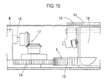
- a rotating shaft 18 of a motor M is coupled to the small gear 16 via bevel gears 17 (see FIG. 10 ).
- the rotator 14 is intermittently rotated by the motor M at a necessary angle (in this embodiment, at an interval of 60 degrees) in a counterclockwise direction as shown by an arrow in FIG. 6 .
- Open holes 19a - 19f are formed in a lid portion 14a of the rotator 14 at the necessary angular interval (see FIG. 7 ).
- Top-opened receiving portions 20a - 20f for receiving tablets amounting to one package are formed in the open holes 19a - 19f respectively. All the top-opened receiving portions 20a - 20f have the same configuration. Thus, hereinafter, they are referred to as the top-opened receiving portion 20 and its configuration will be described. The number of the top-opened receiving portion 20 is optional.
- An outer side wall of the top-opened receiving portion 20 in a diametric direction of the rotator 14 comprises an outer peripheral wall 14b of the rotator 14, while an inner side wall thereof comprises a cylindrical inner wheel 14c (see FIG. 11 ).
- side walls of the top-opened receiving portion, which are opposed in a circumferential direction of the rotator 14, comprises a fixed plate 21, which has a groove-ridge portion 21 a in a vertical direction, and a flat plate-shaped swing plate (propeller plate) 22. Both of the plates 21, 22 are disposed at normal times in the shape of an inverted triangle wherein lower ends of them are in contact with each other (see FIGS. 15A(a) and 16(a) ).
- the swing plate 22 is swingable through a rotating shaft (swing shaft) 23 in an upper end thereof.
- the groove-ridge portion 21a may be formed in the swing plate 22. Further, only the swing plate 22 may comprise a plate with the groove-ridge portion 21 a or both of the plates 21, 22 may comprises a plate without the groove-ridge portion 21 a.
- the groove-ridge portion 21 a by means of a groove-ridge shape thereof, prevents the tablets T as well as an adhesion powder a, which is stripped due to vibration (this will be described below), from not falling as adhering to each plate 21, 22 due to static electricity.
- the groove-ridge portion may comprise a plurality of verrucous protrusions.
- each top-opened receiving portion 20 includes an open hole (tablet discharging outlet) 14d (see FIG. 5 ).
- an open hole (dispensing outlet) 10d through which the tablet powder a and the tablet T pass (fall), is formed in a bottom plate of the housing 10 where the tablet discharging outlet 14d faces to the hopper 3a of the tablet packaging section 3 as well as a portion for removing the tablet powder a (a portion forming protrusions 30a) (this will be described below).
- a cam 30 and a plurality of protrusions 31 a are provided on top of the bottom plate of the housing 10 along the outer periphery of the rotator 14.
- the plurality of the protrusion 31a form a prominence and depression, on which a cam roller 24 (this will be described below) rolls to thereby move vertically.
- the cam roller 24 is coupled to an outward end of the rotating shaft 23 of the swing plate 22 (in the diametrically outward direction of the rotator 14) via a support arm 25.
- the swing plate 22 swings in concomitance with the vertical movement of the cam roller 24 (swings around the rotating shaft 23).
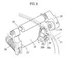
- a spring 26 is provided in an inward end of the rotating shaft 23 of the swing plate 22 via a support arm 27. The spring biases the swing plate 22 at normal times such that the lower end of the swing plate is in contact with the lower end of the fixed plate 21 ( see FIG. 14 ).
- the lower ends of both of the plates 21, 22 may have a gap t , which does not permit the tablet T to fall therethrough even if the lower ends of both of the plates do not contact each other, therebetween.
- a pawl 28 which abuts a back surface of the swing plate 22 to thus regulate the swing of the swing plate, is provided in a support portion 14e that is in the large gear 15 beside the rotator 14.
- the pawl is pivotable through a shaft 28b of a support metal part 28a (see FIGS. 7 , 8 , 11 and 12 ).
- the pawl 28 is biased by a spring 29 at normal times such that a lower end of the pawl is in engagement with the back surface of the swing plate 22.
- the pivotal movement caused by such bias is restricted when an upper portion of the pawl 28 abuts a U-shaped inner wall of the support metal part 28a (as shown by a solid line in FIG. 8 ).
- the cam 30 is supported by a support leg 30c raised from the bottom plate of the housing 10.
- the cam is provided to correspond to the feeding hopper 3a to the tablet packaging section 3 (see FIG. 6 ) and has the same configuration as a cam indicated by reference numeral 82d in FIG. 13 of the above-mentioned Patent Document 1.
- FIGS. 13 show that the cam 30 is supported by a support leg 30c raised from the bottom plate of the housing 10.
- the cam is provided to correspond to the feeding hopper 3a to the tablet packaging section 3 (see FIG. 6 ) and has the same configuration as a cam indicated by reference numeral 82d in FIG. 13 of the above-mentioned Patent Document 1.
- the protrusions 31a are provided on an upper surface of an operating plate 31, which is provided to be raised from the bottom plate of the housing 10.
- the protrusions are provided to correspond to about two intermittent rotations of the rotator 14 (about 150 degrees).
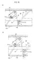
- FIG. 16 if the cam roller 24 rides on the protrusion 31a (as shown from FIG. 16(a) to FIG. 16(b) ), the swing plate 22 is swung through the rotating shaft 23.
- the swing movement of the swing plate 22 is done whenever the cam roller 24 rides on the protrusions 31a.
- the swing plate 22 vibrates as shown through FIG. 16(a) ⁇ FIG. 16(b) ⁇ FIG. 16(a) ⁇ . Due to such vibration, the tablet T between the swing plate 22 and the fixed plate 21 vibrates and bounces.
- the adhesion powder (including fragmented pieces) a touches with an edge of the groove-ridge portion 21 a or is stripped due to difference in fall speed between the adhesion powder and the tablet T.
- the adhesion powder generally moves along groove portions of the groove-ridge portion 21a and falls from the gap t in the lower ends of the both of the plates 21, 22, which is opened due to such vibration, toward the tablet discharging outlet 14d located below the gap.
- the powder a which is prone to adhere to the surfaces of the both of the plates 21, 22 due to static electricity, smoothly falls. Since the powder a falls from the groove portions, the lower ends of the both of the plates 21, 22 may be in contact with each other during the vibration.
- the powder a which has fallen through the tablet discharging outlet 14d and the open hole 10d, falls onto a powder collecting tray 32 (see FIG. 5 ).
- the powder collecting tray 32 is appropriately drawn out to remove the collected powder a.
- a cutout groove 31b is formed in an inner surface of the operating plate 31 and thus avoids interference with the pawl 28 when the swing plate 22 vibrates (see FIGS. 11 and 12 ).
- the powder collecting tray 32 is removably fitted to a guide 32a and is engaged by fitting between a leading edge thereof and a stopper metal part 32b.
- the tablet introducing inlets 13a, 13b, 13c are formed at the intermittent rotation interval (60 degrees interval) from the hopper (introducing inlet) 3 a for the tablet packaging section 3 along the rotation direction of the rotator 14. As one top-opened receiving portion 20 faces to each of the tablet discharging outlets 13a, 13b, 13c in sequence, the tablets T for one package are fed from the both of the tablet storing sections 1, 2 and the manual distribution unit 7.
- the top-opened receiving portion reaches the plurality of protrusions 31a (powder removal portion) and thus removes the adhesion powder a , as shown in FIG. 16 . Thereafter, the top-opened receiving portion is moved toward the hopper 3a for the tablet packaging section 3. If the top-opened receiving portion 20 is moved toward the hopper 3 a, then, as shown from FIG. 15A to FIG. 15B, the upper end of the pawl 28 abuts the lateral surface 30b of the cam 30 and slides, thus releasing the engagement to the swing plate 22. Further, as shown in FIG.
- the cam roller 24 rides on the cam surface 30a and then the swing plate 22 is separated from the fixed plate 21 along with the rolling movement of the cam roller 24 on the cam surface 30a, thereby opening the bottom of the top-opened receiving portion 20. Due to such opening, the tablets T in the top-opened receiving portion 20 fall to the hopper 3a for the tablet packaging section through the tablet discharging outer 14d and the open hole 10d and then the tablets T for one package are packaged by the tablet packaging section 3.
- the groove portions of the groove-ridge portion 21a may comprise a slit located at the bottom opening.
- the powder a falls through the slit, an open hole for the fall of the powder is formed in the bottom plate of the rotator 14 and a tray for receiving the powder a is detachably provided at the bottom of the housing 10. Further, since the powder a fall from such a groove portion, the lower ends of the both of the plates 21, 22 may be in contact with each other during the vibration.
- FIGS. 17 to 20 show another embodiment.
- a trough-shaped metal part 34 is provided on the surface of the fixed plate 21 of the top-opened receiving portion 20.
- a vibration-applying piece 35 which makes a prominence and depression on which the cam roller 24 rolls to thereby move vertically, and a roller 36 are provided in the operating plate 31.
- the metal part 34 is integrated with the cover 33.
- the metal part 34 is surface-treated by a surface treatment wherein a steel, stainless or copper alloy plate is eutectic with nickel and fluorine resin and then is heat-treated, thus having a slip property on its inner surface.
- the metal part 34 is secured to the rotator 14 in such a manner that a cut-raised claw 33a of the cover 33 is inserted and fitted to a hole in the upper surface of the rotator 14. If the metal part 34 has the slip property as described above, the tablets T, T1 or the powder stripped therefrom smoothly fall without any adherence. The vibration generates the static electricity and the static electricity stays. Such smooth fall prevents the static electricity from hindering the fall of the tablets and the powder.
- the fixed plate 21 may have the slip property on its surface by directly coating (applying) the surface of the fixed plate with a slippage agent such as fluorine resin.
- a slippage agent such as fluorine resin.
- the application of the slip property using coating may be done on the swing plate 22. It is a matter of course that the above-described slippage treatment can be employed to the embodiment shown in FIG. 4 , etc.
- the vibration-applying piece 35 is screw-coupled to the operating plate 31. Cutout portions (apertures) 35a are formed in the vibration-applying piece along a rolling movement trajectory of the cam roller 24 and thus the trajectory path becomes the prominence and depression.
- Cutout portions (apertures) 35a are formed in the vibration-applying piece along a rolling movement trajectory of the cam roller 24 and thus the trajectory path becomes the prominence and depression.
- the adhesion powder (including fragmented pieces) a of the tablet comes in touch with the metal part 34 with the slip property surface or is stripped due to difference in fall speed between the powder and the tablets T. Then, the powder falls from the gap t in the lower ends of the both of the plates 21 (34), 22, which is opened due to the vibration, to the tablet discharging outlet 14d located below the gap.
- the vibration-applying piece 35 is preferably made from a metallic material such as stainless in terms of durability, however other material such as plastic may be employed.
- roller 36 is through the operating plate 31. Its attachment frame 36a is screw-coupled to the operating plate and its lower projecting portion is in pressure contact with the upper peripheral surface of the large gear 15 of the rotator 14 ( see FIGS. 19 and 20(a) ). Such pressure contact restrains the vibration of the rotator 14, which is caused by the vibration resulted from the rolling movement of the cam roller 24 on the prominence and depression path. That is, it is restrained that the rotator 14 rattles or ripples due to the application of the vibration to the swing plate 22, thus preventing the bottom of the rotator 14 from touching with another member. It is a matter of course that the roller 36 can be employed to the embodiment shown in FIG. 4 , etc.
- the spring 29, which biases the pawl 28 such that the lower end of the pawl engages the back surface of the swing plate 22 at normal times, is provided between the support metal part 28a and the lower back surface of the pawl 28 (see FIG. 19 ), thus preventing the abrasion powder of the spring 29 and the shaft 29 from being made due to friction between the torsion spring 29 and the shaft 28b shown in FIG. 8 .
- the spring 29 shown in FIG. 19 is a coil spring and is provided in the support metal part 28a by welding one end of the spring to the support metal part 28a. It is a matter of course to employ the configuration of the coil spring 29 to the configuration shown in FIG. 8 .
- the fixed plate 21 may be configured to swing and vibrate.
- the protrusions 31 a or the vibration-applying piece 35 may be provided in another position, e.g., between the introducing inlet 13a and the introducing inlet 13b, or between the introducing inlet 13b and the introducing inlet 13c.
- it is preferred that the position is next to the introducing inlet 13c after the top-opened receiving portion 20 receives the tablets T for one package.
- the position may be next to the introducing inlet 13a.
- the protrusions 31 a may be formed by embossing a portion of the vibration-applying plate 35 by means of a punch.
Landscapes
- Engineering & Computer Science (AREA)
- Mechanical Engineering (AREA)
- Physics & Mathematics (AREA)
- General Physics & Mathematics (AREA)
- Medical Preparation Storing Or Oral Administration Devices (AREA)
- Basic Packing Technique (AREA)
- Supply Of Fluid Materials To The Packaging Location (AREA)
Abstract
Description
- The present invention relates to a powder removal device of a medicine dispenser which dispenses tablets and prepares a medicine according to a prescription in hospitals, clinics, pharmacies, etc.
- By way of example of such a medicine dispenser that prepares a tablet medicine according to a prescription, there is a medicine dispenser which feeds required tablets from a tablet storing section having a plurality of tablet feeders to a tablet packaging section according to a prescription and packages the tablets one package at a time (see
FIGS. 1 to 3 in Patent Document 1). Further, there is another medicine dispenser wherein a tablet storing section comprises the tablet feeders arranged in a shape of a shelf step and, similarly to the aforesaid medicine dispenser, required tablets are fed from the tablet storing section to a tablet packaging section according to a prescription and then is packaged one package at a time (seeFIG. 6 in Patent Document 2). - In the aforesaid medicine dispenser, a tablet preparation section is provided between the tablet storing section and the tablet packaging section. The tablet preparation section keeps together tablets for one package and then feeds the tablets for one package to the tablet packaging section in a lump (see Paragraph [0051],
lines 1 to 2, Paragraphs [0088] and [0101] to [0105] andFIGS. 11 to 15 in Patent Document 1). - Further, by way of example of the aforesaid tablet feeder, there is a tablet feeder wherein: a container for containing a large number of tablets houses a rotating rotor; receiving grooves (recesses) for receiving the tablets are formed in the rotor along an entire periphery of the rotor at equal spacing; along with the rotation of the rotor, the receiving groove receives the tablets in the container and moves the same in the rotation direction; and if the receiving groove faces to a discharge outlet, then the tablets in the receiving groove fall from the receiving groove to the discharge outlet one tablet at a time and thus the tablets are dispensed (see Patent Document 3).
- Further, according to some prescription, a tablet to be taken one time may be a half tablet (the half of a tablet). In this case, it is necessary that a tablet cut and divided into halves in advance be set to the dispensing device and then be dispensed. By way of example of such a tablet divider, there is a tablet divider wherein a pair of belt conveyors sandwich a tablet and transfer the tablet downwardly and a rotary cutter divides the tablet in two halves during the transfer of the tablet (see
FIG. 1 in Patent Document 4). Further, there is another tablet divider wherein a tablet is transferred to a tube and the tablet is stopped by a shutter and then divided in two halves by a cutter during the transfer of the tablet. Further, in said another tablet divider, the tablet piece of a lower half falls, while the tablet piece of an upper half is held on the cutter and then falls along with the retraction of the cutter (seeFIG. 6 in Patent Document 5). - In the aforesaid tablet feeders, when the tablet is dispensed, a portion of the tablet chips or fragment powder is made due to friction. In particular, the feeder dividing the tablet creates powder when dividing the tablet. This is problematic since some medicine takers dislike these powders contained in a package bag for tablets. For this reason, there is a technique wherein a brush rakes powder particles at a halfway point of a dispensing passage from the rotor of the tablet feeder and discharges them through the discharge outlet (see
Claim 3, Paragraph [0024] andFIG. 2 in Patent Document 6). Further, there is another technique wherein powder particles adhering to tablets are removed by suction or air blast in a tablet manufacture process or a tablet inspection process (see Abstract ofPatent Document 7 and Abstract of Patent Document 8). - Patent Document 1: Japanese Laid-Open Patent Application No.
2009-100911 - Patent Document 2: Japanese Laid-Open Patent Application No.
2008-162609 - Patent Document 3: Japanese Laid-Open Patent Application No.
2005-59903 - Patent Document 4: Japanese Laid-Open Patent Application No.
Hei 2-29257 - Patent Document 5: Japanese Laid-Open Patent Application No.
Hei 11-226089 - Patent Document 6: Japanese Laid-Open Patent Application No.
2006-306430 - Patent Document 7: Japanese Laid-Open Patent Application No.
2008-200234 - Patent Document 8: Japanese Laid-Open Patent Application No.
2007-135982 - Patent Document 9: Japanese Laid-Open Patent Application No.
2003-63503 - The process for powder particles described in the above-mentioned
Patent Document 6 is irrelevant to stripping (removing) the adhesion powder particles from the tablet. As a result, the adhesion powder is fed from the tablet storing section to the tablet packaging section together with the tablet. That is, this does not prevent the adhesion powder particles from being contained in a package bag for tablets. Further, it may be considered that the suction means or the air blast means are equipped in a tablet passage of a medicine dispenser to remove the adhesion powder from the tablet. However, this requires a large-scale suction or air blast mechanism and does not facilitate the treatment of the removed powder particles. - Thus, in light of the foregoing circumstances, it is an object of the present invention to perform removal of the powder (powder particles) adhered to the tablet with simple structure.
- To achieve the above object, given that the tablet preparation section temporarily keeps together tablets for one package from the tablet storing section, the present invention removes the tablet-adhered powder by means of vibration in the tablet preparation section. Since the tablet preparation section temporarily keeps together the tablets, the adhesion powder of the tablet can be removed when vibration is applied to the tablets while the tablets are kept together.
- The present invention provides a powder removal device of a medicine dispenser, which feeds a tablet dispensed from a tablet storing section having a plurality of tablet feeders to a tablet packaging section and packages the tablet. The powder removal device is interposed between the tablet storing section and the tablet packaging section to remove a tablet-adhered powder. The powder removal device comprises: a top-opened receiving portion to which a tablet for one package is inputted from the tablet storing section, the top-opened receiving portion being provided between the tablet storing section and the tablet packaging section; means for vibrating the top-opened receiving portion; and means for opening and closing a bottom of the top-opened receiving portion. The bottom of the top-opened receiving portion has a gap, through which the tablet does not fall. The gap is opened by the opening and closing means to the extent of permitting the tablet to fall.
- According to the above-described configuration, the tablet in the top-opened receiving portion is subjected to vibrate due to the vibration of the top-opened receiving portion. The tablet bounces due to such vibration and thus the adhered powder is stripped therefrom. The stripped powder falls downwardly through the gap of the bottom. A powder collecting tray located below the gap in the bottom of the top-opened receiving portion receives the falling powder. The powder collecting tray is detachable. In this case, it is preferred that an inner surface of the receiving portion has a slip property by coating the inner surface with a slippage agent such as fluorine resin or sticking a sheet or plate piece with such a slippage agent coated so that the tablet and the powder stripped therefrom cannot adhere.
- As the configuration of the top-opened receiving portion, the following various shapes may be considered: a rectangular boxlike shape, a cylindrical boxlike shape, an inverted conical boxlike shape, a boxlike shape of an inverted polygonal pyramid such as a boxlike shape of an inverted triangular pyramid or a boxlike shape of an inverted quadrangular pyramid, a boxlike shape of an inverted conical frustum, a boxlike shape of an inverted polygonal frustum such as a boxlike shape of an inverted triangular frustum or a boxlike shape of an inverted quadrangular frustum, or the like. Although the receiving portion may have any one of the above-described shapes, it is preferred that the bottom of the receiving portion has the gap and the tablet powder is stripped by means of vibration and the gap is opened when the powder is discharged. For this reason, "the gap through which the powder does not fall" is a gap for discharging the powder. The gap may not be formed in the bottom except when performing the dispensing operation (see an embodiment to be described below). Widening or narrowing the gap in the bottom can be achieved by moving a member constituting the bottom by means of the opening and closing means.
- As the concrete configuration of the top-opened receiving portion, for example, the following configuration may be employed: a pair of opposing side wall plates constituting the top-opened receiving portion are disposed in a shape of an inverted triangle; both lower ends of the side wall plates have a gap through which the tablet does not fall; and at least one of the pair of the side wall plates is configured to be opened by the opening and closing means of the bottom of the top-opened receiving portion to the extent that the gap in the lower ends of both of the side wall plates permits the tablet to fall therethrough. In the above-described configuration, being opened and closed of both of the side wall plates of the top-opened receiving portions to the extent of permitting the tablet to fall are done by swingably supporting the side wall plate at the upper end thereof and swinging the side wall plate. The aforementioned swing is done by the opening and closing means. Further, for example, the swing may be done by appropriately using an actuator plunger, a motor, means for swinging the side wall plate by a slide movement between the side wall plate and a cam with a cam surface for vertically moving the side wall plate (see an embodiment to be described below), or the like.
- As the vibrating means for the top-opened receiving portion, one of the following is appropriately employed: a vibration motor wherein an eccentric part is provided in a rotating shaft of a motor coupled to the top-opened receiving portion; and means for bringing the top-opened receiving portion into slide contact with a plurality of prominences and depressions in sequence to vibrate the top-opened receiving portion (see an embodiment to be described below).
- Further, it is preferred that the tablet preparation section includes a plurality of the top-opened receiving portions in view of keeping together a large number of tablets for one package and smoothly feeding the tablets for one package to the tablet packaging section in sequence. As the configuration of the tablet preparation section, the following configuration may be employed: a plurality of the top-opened receiving portions are provided in a rotator at equal interval around a rotation center of the rotator; an introducing inlet to the tablet packaging section opens in a portion of a rotation trajectory of each of the top-opened receiving portions; and an introducing inlet from the tablet storing section faces along a rotation direction of the rotator from the introducing inlet (see an embodiment to be described below).
- With regard to the above-described configuration, the following configuration may be employed: at least one of the pair of the opposing side wall plates of the top-opened receiving portion is swingably supported at an upper end thereof and is biased by a spring in a direction of contacting the other side wall plate; the swingable side wall plate is contacted with and separated from a prominence and depression around the rotator; and the swingable side wall plate is swung while maintaining the gap through which the tablet does not fall, thereby applying the vibration. In this case, the aspect that "the swingable side wall plate is swung while maintaining the gap through which the tablet does not fall" also includes that the lower ends of both of the side wall plates are in contact with each other during the vibration. Further, it is preferred that the rotator in its entirety does not rattle due to the vibration. For example, a fixed roller is provided for abutting the rotator to restrain the vibration.
- More specifically, a cam roller may be provided in a swing shaft of the swingable side wall plate via an arm extending in a diametrical direction of the swing shaft and the cam roller may be contacted with and separated from the prominence and depression, thereby applying the vibration. By adjusting the biasing force of the spring, the lower ends of both of the side wall plates may maintain the gap through which the tablet does not fall during the vibration. However, it is very difficult to suitably adjust it. Thus, a stopper, which engages the swingable side wall plate such that the swingable side wall plate maintains the gap, is preferably provided in the rotator. When the gap in the lower ends of both of the side wall plates is opened by the opening and closing means of the bottom of the top-opened receiving portion to the extent of permitting the tablet to fall, the stopper needs to permit such an action. Thus, in such a case, the stopper is configured to release the engagement to the side wall plate. The release of the engagement may be done by a slide movement of a pawl on a cam to be described below.
- Similar to the cam roller described in Patent Document 1 (see Paragraphs [0057] to [0061] and
FIG. 13 in Patent Document 1), the above-described cam roller performs its operation by rolling on a cam surface of the cam provided around the rotator (see Reference numeral 82d inFIG. 13 in Patent Document 1) such that the bottom of the top-opened receiving portion is opened to the extent of permitting the tablet to fall. - The powder removal device can be provided in the tablet preparation section of various medicine dispensers. As for the medicine dispenser with the tablet dividing feeder cutting and dividing a tablet and dispensing the same, it is important to remove the cut powder made due to such division. Thus, it is preferred that the powder removal device is provided in the medicine dispenser with such a tablet dividing feeder. As the configuration of the tablet dividing feeder, the following configuration may be employed: a tablet is transferred in one direction such as a horizontal direction; a fixed blade is positioned on the way of the tablet; the tablet is divided by the fixed blade due to the transfer of the tablet; a lower tablet piece is discharged due to division caused by the fixed blade, while an upper tablet piece rides from the fixed blade onto a support piece adjoining the fixed blade and is held on the support piece; and the upper tablet piece is discharged from the support piece due to its further transfer (see Paragraphs [0048] to [0056] and
FIGS. 6 to 8 ,12 and 13 in Japanese Patent Application No.2010-504097 - According to the present invention, as described above, the powder removal means is provided in the medicine preparation section. Thus, tablets, from which the adhesion powder such as a cut powder is removed to the utmost, are fed to the medicine packaging section, thereby, to the utmost, avoiding that such a powder is contained in a package bag for the tablets.
-
-
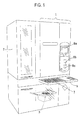
FIG. 1 is a schematic perspective view of a medicine dispenser according to the present invention. -
FIG. 2 is a schematic front view according to the embodiment wherein a front face is removed. -
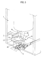
FIG. 3 is a perspective view showing a main part in the embodiment. -
FIG. 4 is a perspective view showing a medicine preparation section in the embodiment. -
FIG. 5 is a lower perspective view of the medicine preparation section. -
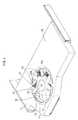
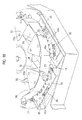
FIG. 6 is a top view showing a main part of the medicine preparation section. -
FIG. 7 is a perspective view showing a main part of the medicine preparation section. -
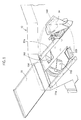
FIG. 8 is a perspective view showing a main part of a top-opened receiving portion of the medicine preparation section. -
FIG. 9 is a sectional view taken along the line IX - IX inFIG. 6 . -
FIG. 10 is a sectional view taken along the line Y-Y inFIG. 6 . -
FIG. 11 is a sectional view taken along the line X - X inFIG. 6 . -
FIG. 12 is an enlarged cutaway view of a main part of the medicine preparation section. -
FIG. 13 is a sectional view taken along the line W - W inFIG. 6 . -
FIG. 14 is a sectional view taken along the line Z - Z inFIG. 6 . -
FIG. 15A illustrates a tablet dispensing operation in the embodiment, wherein (a) is a cutaway front view and (b) is a cutaway side view. -
FIG. 15B illustrates the tablet dispensing operation, wherein (a) is a cutaway front view and (b) is a cutaway side view. -
FIG. 16 illustrates an operation of removing a tablet-adhered powder in the embodiment. -
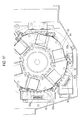
FIG. 17 is a top view showing a main part of a medicine preparation section according to another embodiment. -
FIG. 18 is a perspective view showing a main part of the medicine preparation section. -
FIG. 19 is an enlarged cutaway view showing a main part of the medicine preparation section. -
FIG. 20 illustrates an operation of removing a tablet-adhered powder in the embodiment. - The following embodiment employs the present invention to the medicine dispenser described in the above-mentioned
Patent Document 1. The tablet storing section in this embodiment includes at least one tablet dividing feeder. As described in the specification and drawings of the above-mentioned Japanese Patent Application No.2010-504097 - As shown in
FIGS. 1 and2 , the medicine dispenser includes a maintablet storing section 1 and a subtablet storing section 2. Both of thetablet storing sections FIG. 3 in the above-mentionedPatent Document 1 andFIG. 1 in the above-mentioned Patent Document 9). The tablets T (these include half tablets T1 and are referred to as including the half tablet hereinafter) are dispensed from both of thetablet storing sections medicine preparation section 6 through a medicine-standby mechanism collection hopper transfer device 5. Amedicine packaging section 3 is provided next to themedicine preparation section 6. Further, amanual distribution unit 7, a liquid-crystal manipulation panel 8a, abarcode reader 8b, ajournal printer 8c and a work table 9 are provided in a front face of the medicine dispenser. The configuration and function of them are the same as those described in the above-mentionedPatent Document 1. - The features of the inventions according to this application reside in the
medicine preparation section 6. As shown inFIGS. 3 to 5 , acircular opening 11a is formed in aceiling plate 11 of ahousing 10 of themedicine preparation section 6. Tablet introducing inlets (feeding inlets) 13a, 13b, 13c (collectively, 13) are formed in acover 12 for closing thecircular opening 11a. Thecollection hopper 4a of the maintablet storing section 1, thetransfer device 5 of the subtablet storing section 2 and thecollection hopper 4c of themanual distribution unit 7 are connected to the introducinginlets tablet storing sections manual distribution unit 7 are sequentially fed from each of the introducinginlets FIG. 3 ). - A lidded
cylindrical rotator 14 is provided in thehousing 10 of themedicine preparation section 6. Alarge gear 15 is provided along a periphery of the rotator 14 (seeFIGS. 9 and10 ). Asmall gear 16 is in mesh with thelarge gear 15. A rotatingshaft 18 of a motor M is coupled to thesmall gear 16 via bevel gears 17 (seeFIG. 10 ). Therotator 14 is intermittently rotated by the motor M at a necessary angle (in this embodiment, at an interval of 60 degrees) in a counterclockwise direction as shown by an arrow inFIG. 6 .Open holes 19a - 19f (collectively, 19) are formed in alid portion 14a of therotator 14 at the necessary angular interval (seeFIG. 7 ). Top-opened receiving portions 20a - 20f for receiving tablets amounting to one package are formed in theopen holes 19a - 19f respectively. All the top-opened receiving portions 20a - 20f have the same configuration. Thus, hereinafter, they are referred to as the top-opened receivingportion 20 and its configuration will be described. The number of the top-opened receivingportion 20 is optional. - An outer side wall of the top-opened receiving
portion 20 in a diametric direction of therotator 14 comprises an outerperipheral wall 14b of therotator 14, while an inner side wall thereof comprises a cylindricalinner wheel 14c (seeFIG. 11 ). Further, side walls of the top-opened receiving portion, which are opposed in a circumferential direction of therotator 14, comprises a fixedplate 21, which has a groove-ridge portion 21 a in a vertical direction, and a flat plate-shaped swing plate (propeller plate) 22. Both of theplates FIGS. 15A(a) and 16(a) ). Theswing plate 22 is swingable through a rotating shaft (swing shaft) 23 in an upper end thereof. The groove-ridge portion 21a may be formed in theswing plate 22. Further, only theswing plate 22 may comprise a plate with the groove-ridge portion 21 a or both of theplates ridge portion 21 a. The groove-ridge portion 21 a, by means of a groove-ridge shape thereof, prevents the tablets T as well as an adhesion powder a, which is stripped due to vibration (this will be described below), from not falling as adhering to eachplate - A bottom of the
rotator 14 below each top-opened receivingportion 20 includes an open hole (tablet discharging outlet) 14d (seeFIG. 5 ). Thus, similar to the top-opened receivingportion 20, sixtablet discharging outlets 14d are defined at an interval of 60 degrees. Further, an open hole (dispensing outlet) 10d, through which the tablet powder a and the tablet T pass (fall), is formed in a bottom plate of thehousing 10 where thetablet discharging outlet 14d faces to thehopper 3a of thetablet packaging section 3 as well as a portion for removing the tablet powder a (aportion forming protrusions 30a) (this will be described below). Further, acam 30 and a plurality ofprotrusions 31 a are provided on top of the bottom plate of thehousing 10 along the outer periphery of therotator 14. The plurality of theprotrusion 31a form a prominence and depression, on which a cam roller 24 (this will be described below) rolls to thereby move vertically. - As shown in
FIG. 8 , thecam roller 24 is coupled to an outward end of therotating shaft 23 of the swing plate 22 (in the diametrically outward direction of the rotator 14) via asupport arm 25. Theswing plate 22 swings in concomitance with the vertical movement of the cam roller 24 (swings around the rotating shaft 23). Further, aspring 26 is provided in an inward end of therotating shaft 23 of theswing plate 22 via asupport arm 27. The spring biases theswing plate 22 at normal times such that the lower end of the swing plate is in contact with the lower end of the fixed plate 21 (seeFIG. 14 ). In this case, the lower ends of both of theplates - Further, a
pawl 28, which abuts a back surface of theswing plate 22 to thus regulate the swing of the swing plate, is provided in asupport portion 14e that is in thelarge gear 15 beside therotator 14. The pawl is pivotable through ashaft 28b of asupport metal part 28a (seeFIGS. 7 ,8 ,11 and12 ). Thepawl 28 is biased by aspring 29 at normal times such that a lower end of the pawl is in engagement with the back surface of theswing plate 22. The pivotal movement caused by such bias is restricted when an upper portion of thepawl 28 abuts a U-shaped inner wall of thesupport metal part 28a (as shown by a solid line inFIG. 8 ). Further, as shown from a chain line to a solid line inFIG. 13 , if the upper end of the pawl slides to alateral surface 30b of the cam 30 (lateral cam surface) (this will be described below), then such slide pushes the upper end of thepawl 28 toward theswing plate 22 against thespring 29, thereby releasing the engagement between the lower end of the pawl and the back surface of theswing plate 22. When the engagement is released, theswing plate 22 can swing (pivot) further upwardly. - As shown in
FIG. 13 , thecam 30 is supported by asupport leg 30c raised from the bottom plate of thehousing 10. The cam is provided to correspond to thefeeding hopper 3a to the tablet packaging section 3 (seeFIG. 6 ) and has the same configuration as a cam indicated by reference numeral 82d inFIG. 13 of the above-mentionedPatent Document 1. As shown in FIGS. 15A to 15B, if thecam roller 24 rides on the cam surface (upper cam surface) 30a of thecam 30, then thecam roller 24 gradually ascends (moves upward) along thecam surface 30a and thus swings theswing plate 22 away from the fixedplate 21 against thespring 26 to greatly open the gap t in the lower end of the fixed plate 21 (to open theswing plate 22 and the fixed plate 21 (the bottom of the top-opened receiving portion)) such that the tablet T smoothly falls therethrough. Thereafter, the cam roller descends and, in concomitance with such descending movement, theswing plate 22 is swung by thespring 26 to abut the fixed plate 21 (FIG. 15A → FIG. 15B → FIG. 15A (however, thecam roller 24 is positioned in the opposite side on thecam surface 30a)). - As shown in
FIGS. 11 and12 , theprotrusions 31a are provided on an upper surface of an operatingplate 31, which is provided to be raised from the bottom plate of thehousing 10. For example, the protrusions are provided to correspond to about two intermittent rotations of the rotator 14 (about 150 degrees). As shown inFIG. 16 , if thecam roller 24 rides on theprotrusion 31a (as shown fromFIG. 16(a) to FIG. 16(b) ), theswing plate 22 is swung through the rotatingshaft 23. In this case, since such swing movement is made within a range (the gap t) regulated by thepawl 28, the lower end of theswing plate 22 and the lower end of the fixedplate 21 are only spaced from each other to the extent that the tablet T (the half tablet T1) cannot fall therethrough. - The swing movement of the
swing plate 22 is done whenever thecam roller 24 rides on theprotrusions 31a. Thus, theswing plate 22 vibrates as shown throughFIG. 16(a) →FIG. 16(b) →FIG. 16(a) ···. Due to such vibration, the tablet T between theswing plate 22 and the fixedplate 21 vibrates and bounces. Thus, the adhesion powder (including fragmented pieces) a touches with an edge of the groove-ridge portion 21 a or is stripped due to difference in fall speed between the adhesion powder and the tablet T. Then, the adhesion powder generally moves along groove portions of the groove-ridge portion 21a and falls from the gap t in the lower ends of the both of theplates tablet discharging outlet 14d located below the gap. In this case, with the vibration as well as the groove-ridge portion 21a, the powder a, which is prone to adhere to the surfaces of the both of theplates plates tablet discharging outlet 14d and theopen hole 10d, falls onto a powder collecting tray 32 (seeFIG. 5 ). Thepowder collecting tray 32 is appropriately drawn out to remove the collected powder a. - A
cutout groove 31b is formed in an inner surface of the operatingplate 31 and thus avoids interference with thepawl 28 when theswing plate 22 vibrates (seeFIGS. 11 and12 ). Thepowder collecting tray 32 is removably fitted to aguide 32a and is engaged by fitting between a leading edge thereof and astopper metal part 32b. - The
tablet introducing inlets tablet packaging section 3 along the rotation direction of therotator 14. As one top-opened receivingportion 20 faces to each of thetablet discharging outlets tablet storing sections manual distribution unit 7. - Thus, after the tablets T have passed through each
tablet introducing inlet portion 20, the top-opened receiving portion reaches the plurality ofprotrusions 31a (powder removal portion) and thus removes the adhesion powder a, as shown inFIG. 16 . Thereafter, the top-opened receiving portion is moved toward thehopper 3a for thetablet packaging section 3. If the top-opened receivingportion 20 is moved toward thehopper 3 a, then, as shown from FIG. 15A to FIG. 15B, the upper end of thepawl 28 abuts thelateral surface 30b of thecam 30 and slides, thus releasing the engagement to theswing plate 22. Further, as shown in FIG. 15B, thecam roller 24 rides on thecam surface 30a and then theswing plate 22 is separated from the fixedplate 21 along with the rolling movement of thecam roller 24 on thecam surface 30a, thereby opening the bottom of the top-opened receivingportion 20. Due to such opening, the tablets T in the top-opened receivingportion 20 fall to thehopper 3a for the tablet packaging section through the tablet discharging outer 14d and theopen hole 10d and then the tablets T for one package are packaged by thetablet packaging section 3. - If the
cam roller 24 reaches a terminal end of thecam surface 30a, then the lower ends of both of theplates pawl 28 is not allowed to slide to thelateral surface 30b of thecam 30 and the lower end of thepawl 28 is brought into engagement with the back surface of theswing plate 22 due to thespring 29, thereby regulating the swing movement of theswing plate 22. By repeating the above-described operations, the followings are performed in sequence: inputting the tablets T for one package to the top-openedreceiving portions 20; removing the adhesion powder by means of vibration; and feeding the tablets T without the adhesion powder to thetablet packaging section 3. Further, the packaging operations for one package according to a prescription are performed in sequence. In the figures,reference numeral 33 indicates a cover closing a portion of the top of the top-opened receivingportion 20. - Further, the groove portions of the groove-
ridge portion 21a may comprise a slit located at the bottom opening. In this case, since the powder a falls through the slit, an open hole for the fall of the powder is formed in the bottom plate of therotator 14 and a tray for receiving the powder a is detachably provided at the bottom of thehousing 10. Further, since the powder a fall from such a groove portion, the lower ends of the both of theplates -
FIGS. 17 to 20 show another embodiment. In this embodiment, a trough-shapedmetal part 34 is provided on the surface of the fixedplate 21 of the top-opened receivingportion 20. Further, a vibration-applyingpiece 35, which makes a prominence and depression on which thecam roller 24 rolls to thereby move vertically, and aroller 36 are provided in the operatingplate 31. - The
metal part 34 is integrated with thecover 33. Themetal part 34 is surface-treated by a surface treatment wherein a steel, stainless or copper alloy plate is eutectic with nickel and fluorine resin and then is heat-treated, thus having a slip property on its inner surface. Themetal part 34 is secured to therotator 14 in such a manner that a cut-raisedclaw 33a of thecover 33 is inserted and fitted to a hole in the upper surface of therotator 14. If themetal part 34 has the slip property as described above, the tablets T, T1 or the powder stripped therefrom smoothly fall without any adherence. The vibration generates the static electricity and the static electricity stays. Such smooth fall prevents the static electricity from hindering the fall of the tablets and the powder. Instead of themetal part 34, the fixedplate 21 may have the slip property on its surface by directly coating (applying) the surface of the fixed plate with a slippage agent such as fluorine resin. The application of the slip property using coating may be done on theswing plate 22. It is a matter of course that the above-described slippage treatment can be employed to the embodiment shown inFIG. 4 , etc. - The vibration-applying
piece 35 is screw-coupled to the operatingplate 31. Cutout portions (apertures) 35a are formed in the vibration-applying piece along a rolling movement trajectory of thecam roller 24 and thus the trajectory path becomes the prominence and depression. Thus, if thecam roller 24 rolls on such a prominence and depression path, as shown inFIG. 20 , then thecam roller 24 vertically moves along such prominence and depression. Further, in concomitance with such a vertical movement, theswing plate 22 swings and vibrates through the rotatingshaft 23 as shown inFIG. 20(a) →FIG. 20(b) →FIG. 20(a) ···. With such vibration, the tablets T between theswing plate 22 and the fixed plate 21 (the metal part 34) vibrate and bounce. Further, the adhesion powder (including fragmented pieces) a of the tablet comes in touch with themetal part 34 with the slip property surface or is stripped due to difference in fall speed between the powder and the tablets T. Then, the powder falls from the gap t in the lower ends of the both of the plates 21 (34), 22, which is opened due to the vibration, to thetablet discharging outlet 14d located below the gap. The vibration-applyingpiece 35 is preferably made from a metallic material such as stainless in terms of durability, however other material such as plastic may be employed. - Further, the
roller 36 is through the operatingplate 31. Itsattachment frame 36a is screw-coupled to the operating plate and its lower projecting portion is in pressure contact with the upper peripheral surface of thelarge gear 15 of the rotator 14 (seeFIGS. 19 and20(a) ). Such pressure contact restrains the vibration of therotator 14, which is caused by the vibration resulted from the rolling movement of thecam roller 24 on the prominence and depression path. That is, it is restrained that therotator 14 rattles or ripples due to the application of the vibration to theswing plate 22, thus preventing the bottom of therotator 14 from touching with another member. It is a matter of course that theroller 36 can be employed to the embodiment shown inFIG. 4 , etc. - Further, in this embodiment, the
spring 29, which biases thepawl 28 such that the lower end of the pawl engages the back surface of theswing plate 22 at normal times, is provided between thesupport metal part 28a and the lower back surface of the pawl 28 (seeFIG. 19 ), thus preventing the abrasion powder of thespring 29 and theshaft 29 from being made due to friction between thetorsion spring 29 and theshaft 28b shown inFIG. 8 . Thespring 29 shown inFIG. 19 is a coil spring and is provided in thesupport metal part 28a by welding one end of the spring to thesupport metal part 28a. It is a matter of course to employ the configuration of thecoil spring 29 to the configuration shown inFIG. 8 . - In each of the foregoing embodiments, similar to the
swing plate 22, the fixedplate 21 may be configured to swing and vibrate. Further, theprotrusions 31 a or the vibration-applying piece 35 (cutout portions 35a) may be provided in another position, e.g., between the introducinginlet 13a and the introducinginlet 13b, or between the introducinginlet 13b and the introducinginlet 13c. However, as described in the foregoing embodiments, it is preferred that the position is next to the introducinginlet 13c after the top-opened receivingportion 20 receives the tablets T for one package. However, in case the cut and divided tablets fall, for example, in case the tablet dividing feeder is in the maintablet storing section 1, the position may be next to the introducinginlet 13a. Theprotrusions 31 a may be formed by embossing a portion of the vibration-applyingplate 35 by means of a punch. -
- T ···
- Tablet
- T1 ···
- Half tablet
- 1 ···
- Main tablet storing section
- 2 ···
- Sub tablet storing section
- 3 ···
- Tablet packaging section
- 3a ···
- Feeding hopper to tablet packaging section
- 4a, 4b, 4c ···
- Tablet collection hopper
- 8 ···
- Tablet preparation section
- 10 ···
- Housing of tablet preparation section
- 12 ···
- Ceiling plate of housing
- 20 ···
- Top-opened receiving portion
- 21 ···
- Fixed plate
- 21 a ···
- Groove-ridge portion
- 22 ···
- Swing plate
- 23 ···
- Rotating shaft of swing plate
- 24 ···
- Cam roller
- 26 ···
- Spring for biasing swing plate
- 30 ···
- Cam for opening swing plate
- 31 a ···
- Prominence and depression forming protrusions for applying vibration to swing plate
- 34 ···
- Metal part with slip property
- 35 ···
- Vibration-applying piece
- 35a ···
- Prominence and depression forming cutaway portions for applying vibration to swing plate
- 36 ···
- Roller for restricting vibration of rotator
Claims (10)
- A powder removal device of a medicine dispenser, the medicine dispenser feeding a tablet (T, T1) dispensed from a tablet storing section (1, 2) having a plurality of tablet feeders to a tablet packaging section (3) and packaging the tablet, the powder removal device interposed between the tablet storing section (1, 2) and the tablet packaging section to remove a tablet-adhered powder (a), the powder removal device comprising:a top-opened receiving portion (20) to which a tablet (T, T1) for one package is inputted from the tablet storing section (1, 2), the top-opened receiving portion being provided between the tablet storing section (1, 2) and the tablet packaging section (3);means for vibrating the top-opened receiving portion (20); andmeans for opening and closing a bottom of the top-opened receiving portion (20),wherein the bottom of the top-opened receiving portion (20) has a gap (t), through which the tablet (T, T1) does not fall, andwherein the gap (t) is opened by the opening and closing means to an extent of permitting the tablet (T, T1) to fall.
- The powder removal device of Claim 1, wherein the top-opened receiving portion (20) includes a pair of opposing side wall plates (21, 22) disposed in a shape of an inverted triangle,
wherein both lower ends of the side wall plates have a gap (t) through which the tablet (T, T1) does not fall, and
wherein at least one (22) of the pair of the side wall plates is opened by the opening and closing means for the bottom of the top-opened receiving portion (20) to an extent that the gap (t) in the lower ends of both of the side wall plates (21, 22) permits the tablet (T, T1) to fall. - The powder removal device of Claim 1 or 2, wherein a plurality of the top-opened receiving portions (20) are provided in a rotator (14) at equal interval around a rotation center of the rotator,
wherein an introducing inlet (3 a) to the tablet packaging section (3) opens in a portion of a rotation trajectory of each of the top-opened receiving portions (20), and
wherein an introducing inlet (13a, 13b) from the tablet storing section (1, 2) faces along a rotation direction of the rotator (14) from the introducing inlet (3 a). - The powder removal device of Claim 3, wherein a roller (36) is provided in a fixed member (31) opposed to the rotator (14), the roller being in pressure contact with the rotator (14), and
wherein a pressure contact of the roller (36) restrains a vibration caused by the means for vibrating the top-opened receiving portion (20) of the rotator (14). - The powder removal device of Claim 3 or 4, wherein the at least one of the pair of the opposing side wall plates (21, 22) of the top-opened receiving portion (20) is swingably supported at an upper end thereof and is biased by a spring (26) in a direction of contacting the other side wall plate (21),
wherein the swingable side wall plate (22) is contacted with and separated from a prominence and depression (31a, 35a) around the rotator (14), and
wherein the swingable side wall plate is swung while maintaining the gap (t), through which the tablet (T, T1) does not fall, thereby applying the vibration. - The powder removal device of Claim 5, wherein a cam roller (24) is provided in a swing shaft (23) of the swingable side wall plate (22) via an arm (25) extending in a diametrical direction of the swing shaft, and
wherein the cam roller (24) is contacted with and separated from the prominence and depression (31a, 35a), thereby applying the vibration. - The powder removal device of Claim 6, wherein the swingable side wall plate (22) is swung to thereby open and close the bottom of the top-opened receiving portion (20),
wherein a stopper (28) is provided in the rotator (14) to engage the side wall plate (22) such that the swingable side wall plate (22) maintains the gap (t) through which the tablet (T, T1) does not fall, and
wherein the stopper (28) is configured to release an engagement to the side wall plate (22) when the gap (t) of the lower ends of both of the side wall plates (21, 22) is opened by the opening and closing means of the bottom of the top-opened receiving portion (20) to the extent of permitting the tablet (T, T1) to fall. - The powder removal device of Claim 6 or 7, wherein the cam roller (24) rolls on a cam surface (30a) of a cam (30) provided around the rotator (14), thereby swing the side wall plates (21, 22) to thus open the gap (t) of the lower ends of the side wall plates to the extent of permitting the tablet (T, T1) to fall.
- The powder removal device of any one of Claims 1 to 8, wherein a powder collecting tray (32) is provided below the gap (t) of the bottom of the top-opened receiving portion (20), the tray receiving the adhesion powder (a) of the tablet (T, T1) discharged from the gap (t).
- The powder removal device of any one of Claims 1 to 9, wherein the tablet feeder cuts and divides the tablet (T).
Applications Claiming Priority (3)
| Application Number | Priority Date | Filing Date | Title |
|---|---|---|---|
| JP2010044471 | 2010-03-01 | ||
| JP2010152004 | 2010-07-02 | ||
| PCT/JP2011/054249 WO2011108448A1 (en) | 2010-03-01 | 2011-02-25 | Powder removal device of medicine dispenser |
Publications (2)
| Publication Number | Publication Date |
|---|---|
| EP2543603A1 true EP2543603A1 (en) | 2013-01-09 |
| EP2543603A4 EP2543603A4 (en) | 2017-11-29 |
Family
ID=44542101
Family Applications (1)
| Application Number | Title | Priority Date | Filing Date |
|---|---|---|---|
| EP11750558.6A Withdrawn EP2543603A4 (en) | 2010-03-01 | 2011-02-25 | Powder removal device of medicine dispenser |
Country Status (6)
| Country | Link |
|---|---|
| US (1) | US9333541B2 (en) |
| EP (1) | EP2543603A4 (en) |
| JP (1) | JP4786002B1 (en) |
| KR (1) | KR101860578B1 (en) |
| CN (1) | CN102770348B (en) |
| WO (1) | WO2011108448A1 (en) |
Cited By (2)
| Publication number | Priority date | Publication date | Assignee | Title |
|---|---|---|---|---|
| CN107578565A (en) * | 2017-10-21 | 2018-01-12 | 迈为医疗技术(深圳)有限公司 | A kind of dispensing layer of box agent dispensing machine |
| CN112896655A (en) * | 2021-02-20 | 2021-06-04 | 烟台久和开源健康营养中心 | Multilayer capsule dust removal device and using method thereof |
Families Citing this family (21)
| Publication number | Priority date | Publication date | Assignee | Title |
|---|---|---|---|---|
| CN102327188B (en) | 2008-09-18 | 2015-04-01 | 株式会社汤山制作所 | Tablet feeder |
| CN102341307B (en) * | 2009-03-05 | 2014-12-17 | 株式会社汤山制作所 | Powder removing device for tablet feeder |
| WO2013105198A1 (en) * | 2012-01-11 | 2013-07-18 | パナソニックヘルスケア株式会社 | Drug supply device, and drug inspection method in drug supply device |
| WO2013141130A1 (en) * | 2012-03-21 | 2013-09-26 | 株式会社湯山製作所 | Drug-supplying device and drug-counting device |
| CN103332307A (en) * | 2013-07-09 | 2013-10-02 | 江苏绿天源系统工程有限公司 | Air exhausting and bag placing synchronous on-line device of packing scale and implement method |
| ITBO20130392A1 (en) * | 2013-07-23 | 2015-01-24 | Gd Spa | EMBOSSING DEVICE, PACKING MACHINE INCLUDING THIS DEVICE |
| KR102602951B1 (en) * | 2015-06-29 | 2023-11-16 | 가부시키가이샤 유야마 세이사쿠쇼 | drug dispensing device |
| JP6738592B2 (en) * | 2015-07-02 | 2020-08-12 | 株式会社タカゾノテクノロジー | Medicine packaging device and medicine supply device |
| CN107499544B (en) * | 2016-06-14 | 2020-03-20 | Jvm有限公司 | Medicine packaging equipment |
| CN108424337A (en) * | 2018-05-12 | 2018-08-21 | 浏阳市鸿安机械制造有限公司 | Without sulfur granules medicine production line |
| EP3616675B1 (en) * | 2018-08-31 | 2021-04-14 | Becton Dickinson Rowa Germany GmbH | Storage container for a storage and dispensing station for medicaments |
| US10945924B2 (en) | 2018-08-31 | 2021-03-16 | Becton Dickinson Rowa Germany Gmbh | Storage container for a storage and dispensing station for pharmaceuticals |
| GB2578601A (en) * | 2018-10-31 | 2020-05-20 | Ishida Europe Ltd | Slack separation apparatus and method |
| JP7580686B2 (en) * | 2019-09-12 | 2024-11-12 | 株式会社トーショー | Tablet splitting device |
| EP3925590B1 (en) | 2020-06-16 | 2025-01-08 | Becton Dickinson Rowa Germany GmbH | Storage container for a storage and dispensing station |
| US11352194B2 (en) | 2020-06-16 | 2022-06-07 | Becton Dickinson Rowa Germany Gmbh | Storage container for a storage and dispensing station |
| CN113000370A (en) * | 2021-03-10 | 2021-06-22 | 重庆医药高等专科学校 | Tablet gumming device |
| CN115092429A (en) * | 2022-07-19 | 2022-09-23 | 姚燕 | A medicine storage and automatic dispensing device constituting a smart Chinese pharmacy |
| JP2024048740A (en) * | 2022-09-28 | 2024-04-09 | 株式会社タカゾノ | Drug Delivery Device |
| CN116923772B (en) * | 2023-06-07 | 2026-01-02 | 北京同仁堂参茸中药制品有限公司 | A type of herbal medicine dispensing machine |
| CN117302690B (en) * | 2023-11-27 | 2024-02-02 | 山西心言生物科技有限公司 | High-efficient many class fungus package classification packagine machine that punches a hole |
Family Cites Families (44)
| Publication number | Priority date | Publication date | Assignee | Title |
|---|---|---|---|---|
| FR668775A (en) * | 1928-05-15 | 1929-11-06 | Vibration distributor | |
| US2200472A (en) * | 1938-06-29 | 1940-05-14 | Schering Corp | Granular material separating machine |
| US2425984A (en) * | 1942-09-26 | 1947-08-19 | Blackman Stanley | Method for cleaning capsules and the like |
| US2617137A (en) * | 1948-03-22 | 1952-11-11 | Bodnar Alexander | Apparatus for dusting capsules |
| US2918691A (en) * | 1957-05-06 | 1959-12-29 | Lilly Co Eli | Capsule cleaning device |
| US3096532A (en) * | 1960-05-05 | 1963-07-09 | Stokes F J Corp | Tablet duster |
| US3693320A (en) * | 1970-11-09 | 1972-09-26 | Carl C Garland | Novel capsule finishing apparatus |
| US3774368A (en) * | 1972-06-19 | 1973-11-27 | H Paprzycki | Tablet counting and filling apparatus |
| US4003831A (en) * | 1974-09-20 | 1977-01-18 | Anatoly Yakovlevich Tishkov | Vibration screen |
| DE2657565C3 (en) * | 1976-12-18 | 1980-10-02 | Truetzschler Gmbh & Co Kg, 4050 Moenchengladbach | Device for cleaning and dedusting textile fiber flocks |
| US4379509A (en) * | 1981-01-15 | 1983-04-12 | Lorenz Bohle | High efficiency sorting apparatus |
| JP2656805B2 (en) | 1988-07-19 | 1997-09-24 | 園部 尚俊 | Tablet splitting machine |
| US4933074A (en) * | 1988-11-10 | 1990-06-12 | The Boeing Company | Article singulating system and method |
| CN2084375U (en) * | 1990-06-27 | 1991-09-11 | 杨承霖 | Powder revomer |
| IT1249230B (en) * | 1991-06-12 | 1995-02-21 | Ima Spa | APPARATUS FOR SELECTING HARD JELLY CAPSULES. |
| JPH06262150A (en) * | 1992-05-12 | 1994-09-20 | Matsui Mfg Co | Method and device for removing depositions |
| JP3554580B2 (en) * | 1994-03-01 | 2004-08-18 | 塩野義製薬株式会社 | Discharge chute of powder material compression molding equipment |
| US5661249A (en) * | 1994-08-11 | 1997-08-26 | Walter Grassle Gmbh | Apparatus and method for inspecting small articles |
| JP3428609B2 (en) * | 1996-03-29 | 2003-07-22 | 株式会社サタケ | Coarse stone removal device |
| DE19654612C2 (en) * | 1996-12-20 | 1999-07-01 | Korsch Pressen Ag | Method and device for checking tablet parameters |
| JP4153061B2 (en) * | 1997-10-23 | 2008-09-17 | 株式会社湯山製作所 | Tablet packaging equipment |
| US6488192B1 (en) | 1999-04-21 | 2002-12-03 | Yuyama Mfg. Co., Ltd. | Tablet cutting apparatus |
| JP4097760B2 (en) * | 1998-01-20 | 2008-06-11 | 株式会社トーショー | Dispensing device |
| JP3969825B2 (en) | 1998-02-12 | 2007-09-05 | 株式会社トーショー | Tablet packing machine and tablet supply device |
| JP4060970B2 (en) | 1999-01-20 | 2008-03-12 | 株式会社湯山製作所 | Cleaner device |
| JP3790688B2 (en) | 2001-08-21 | 2006-06-28 | 株式会社湯山製作所 | Tablet feeder |
| DE10242243B4 (en) * | 2002-09-12 | 2004-07-08 | Uhlmann Pac-Systeme Gmbh & Co. Kg | Device for sorting products |
| JP4050981B2 (en) * | 2002-12-20 | 2008-02-20 | 株式会社湯山製作所 | Drug packaging device |
| JP2004344398A (en) * | 2003-05-22 | 2004-12-09 | Hayashi Yakuhin Kikai Kk | Device for removing tablet powders |
| JP2005059903A (en) | 2003-08-13 | 2005-03-10 | Yuyama Manufacturing Co Ltd | Tablet feeder |
| CN100553993C (en) * | 2004-10-08 | 2009-10-28 | 株式会社汤山制作所 | Medicament dispensing device |
| JP4473170B2 (en) * | 2005-04-27 | 2010-06-02 | 高園産業株式会社 | Tablet cassette |
| JP2007135982A (en) | 2005-11-21 | 2007-06-07 | Bushu Seiyaku Kk | Tablet conveyance apparatus |
| JP2007284087A (en) | 2006-04-14 | 2007-11-01 | Ckd Corp | Bowl feeder for tablet supply |
| EP2069512B1 (en) | 2006-09-22 | 2010-06-16 | Danisco US, INC., Genencor Division | Acetolactate synthase from trichoderma reesei as selectable marker |
| JP4952241B2 (en) | 2006-12-27 | 2012-06-13 | 株式会社湯山製作所 | Hopper device in medicine packaging machine |
| JP4952291B2 (en) | 2007-02-20 | 2012-06-13 | 大正製薬株式会社 | Tablet transport guide method |
| KR101379990B1 (en) | 2007-10-23 | 2014-04-02 | 가부시키가이샤 유야마 세이사쿠쇼 | Drug delivery system, and drug delivery device |
| JP5169137B2 (en) | 2007-10-23 | 2013-03-27 | 株式会社湯山製作所 | Drug dispensing apparatus and drug dispensing system |
| JP4104161B1 (en) * | 2007-11-02 | 2008-06-18 | 株式会社湯山製作所 | Partition plate used for V-shaped medicine packaging machine |
| PL2128026T3 (en) * | 2008-05-26 | 2012-07-31 | Zanichelli Mecc S P A | Circular filling machine particularly for slender and elongated products |
| CN102327188B (en) | 2008-09-18 | 2015-04-01 | 株式会社汤山制作所 | Tablet feeder |
| CN102341307B (en) * | 2009-03-05 | 2014-12-17 | 株式会社汤山制作所 | Powder removing device for tablet feeder |
| US7882959B1 (en) * | 2009-08-06 | 2011-02-08 | General Mills Ip Holdings Ii, Llc | Method and apparatus for scalping food pieces |
-
2011
- 2011-02-25 WO PCT/JP2011/054249 patent/WO2011108448A1/en not_active Ceased
- 2011-02-25 KR KR1020127022410A patent/KR101860578B1/en active Active
- 2011-02-25 US US13/581,515 patent/US9333541B2/en active Active
- 2011-02-25 JP JP2011517128A patent/JP4786002B1/en not_active Expired - Fee Related
- 2011-02-25 EP EP11750558.6A patent/EP2543603A4/en not_active Withdrawn
- 2011-02-25 CN CN201180010477.2A patent/CN102770348B/en active Active
Non-Patent Citations (1)
| Title |
|---|
| See references of WO2011108448A1 * |
Cited By (2)
| Publication number | Priority date | Publication date | Assignee | Title |
|---|---|---|---|---|
| CN107578565A (en) * | 2017-10-21 | 2018-01-12 | 迈为医疗技术(深圳)有限公司 | A kind of dispensing layer of box agent dispensing machine |
| CN112896655A (en) * | 2021-02-20 | 2021-06-04 | 烟台久和开源健康营养中心 | Multilayer capsule dust removal device and using method thereof |
Also Published As
| Publication number | Publication date |
|---|---|
| KR20130014499A (en) | 2013-02-07 |
| WO2011108448A1 (en) | 2011-09-09 |
| JP4786002B1 (en) | 2011-10-05 |
| CN102770348A (en) | 2012-11-07 |
| CN102770348B (en) | 2014-07-30 |
| KR101860578B1 (en) | 2018-05-23 |
| US9333541B2 (en) | 2016-05-10 |
| US20120324828A1 (en) | 2012-12-27 |
| EP2543603A4 (en) | 2017-11-29 |
| JPWO2011108448A1 (en) | 2013-06-27 |
Similar Documents
| Publication | Publication Date | Title |
|---|---|---|
| US9333541B2 (en) | Powder removal device of medicine dispenser | |
| CN102341307B (en) | Powder removing device for tablet feeder | |
| US10647455B2 (en) | Tablet packaging device | |
| JP5950876B2 (en) | Drug feeder | |
| EP2791012B1 (en) | Device and method for dispensing and packing solid substances | |
| EP2345399A1 (en) | Tablet feeder | |
| US8733586B2 (en) | Drug sorting device | |
| US7516836B2 (en) | Centrifugal filling apparatus and method | |
| JP7249013B2 (en) | drug supply device | |
| JP2021016598A (en) | General-purpose medicament supply device and medicament packing device | |
| WO2022124369A1 (en) | Drug feeder | |
| KR200482491Y1 (en) | Transfer Device Of Pill | |
| CA2874976C (en) | Article dispensing | |
| US2701671A (en) | Tablet counter | |
| JP6924463B1 (en) | Drug packaging machine with general-purpose tablet release device and general-purpose tablet release device | |
| JP2021053114A (en) | Medicament supply device and medicament packing device | |
| JP7081799B2 (en) | Tablet supply device and drug delivery device | |
| WO2017043430A1 (en) | Tablet packaging apparatus | |
| KR20150042397A (en) | Medicine dispensing device | |
| JP2024153256A (en) | Tablet cutter | |
| JP2026082609A (en) | Powder feeding device and drug dispensing device | |
| JP2021061902A (en) | Medicine supply apparatus and medicine packaging apparatus | |
| JPH0544138U (en) | Dispensing device |
Legal Events
| Date | Code | Title | Description |
|---|---|---|---|
| PUAI | Public reference made under article 153(3) epc to a published international application that has entered the european phase |
Free format text: ORIGINAL CODE: 0009012 |
|
| 17P | Request for examination filed |
Effective date: 20120828 |
|
| AK | Designated contracting states |
Kind code of ref document: A1 Designated state(s): AL AT BE BG CH CY CZ DE DK EE ES FI FR GB GR HR HU IE IS IT LI LT LU LV MC MK MT NL NO PL PT RO RS SE SI SK SM TR |
|
| DAX | Request for extension of the european patent (deleted) | ||
| RA4 | Supplementary search report drawn up and despatched (corrected) |
Effective date: 20171103 |
|
| RIC1 | Information provided on ipc code assigned before grant |
Ipc: B65B 55/00 20060101ALI20171026BHEP Ipc: A61J 3/00 20060101ALI20171026BHEP Ipc: B65B 39/00 20060101ALI20171026BHEP Ipc: G07F 17/00 20060101ALI20171026BHEP Ipc: B08B 7/02 20060101AFI20171026BHEP |
|
| STAA | Information on the status of an ep patent application or granted ep patent |
Free format text: STATUS: EXAMINATION IS IN PROGRESS |
|
| 17Q | First examination report despatched |
Effective date: 20200108 |
|
| RAP1 | Party data changed (applicant data changed or rights of an application transferred) |
Owner name: YUYAMA MFG. CO., LTD. |
|
| GRAP | Despatch of communication of intention to grant a patent |
Free format text: ORIGINAL CODE: EPIDOSNIGR1 |
|
| STAA | Information on the status of an ep patent application or granted ep patent |
Free format text: STATUS: GRANT OF PATENT IS INTENDED |
|
| INTG | Intention to grant announced |
Effective date: 20230317 |
|
| STAA | Information on the status of an ep patent application or granted ep patent |
Free format text: STATUS: THE APPLICATION IS DEEMED TO BE WITHDRAWN |
|
| 18D | Application deemed to be withdrawn |
Effective date: 20230728 |