EP2543485B1 - Device for cutting a food product - Google Patents
Device for cutting a food product Download PDFInfo
- Publication number
- EP2543485B1 EP2543485B1 EP20120174954 EP12174954A EP2543485B1 EP 2543485 B1 EP2543485 B1 EP 2543485B1 EP 20120174954 EP20120174954 EP 20120174954 EP 12174954 A EP12174954 A EP 12174954A EP 2543485 B1 EP2543485 B1 EP 2543485B1
- Authority
- EP
- European Patent Office
- Prior art keywords
- carriage
- conveying direction
- driver
- accordance
- hollow space
- Prior art date
- Legal status (The legal status is an assumption and is not a legal conclusion. Google has not performed a legal analysis and makes no representation as to the accuracy of the status listed.)
- Active
Links
- 235000013305 food Nutrition 0.000 title claims description 10
- 238000005520 cutting process Methods 0.000 title claims description 9
- 239000012530 fluid Substances 0.000 claims description 20
- 230000033001 locomotion Effects 0.000 claims description 15
- 235000013351 cheese Nutrition 0.000 claims description 2
- 235000013372 meat Nutrition 0.000 claims description 2
- 235000013580 sausages Nutrition 0.000 claims description 2
- 239000011796 hollow space material Substances 0.000 claims 10
- 230000009977 dual effect Effects 0.000 claims 1
- 239000000696 magnetic material Substances 0.000 claims 1
- 239000000463 material Substances 0.000 claims 1
- 238000000034 method Methods 0.000 description 4
- 230000008569 process Effects 0.000 description 4
- 230000008878 coupling Effects 0.000 description 3
- 238000010168 coupling process Methods 0.000 description 3
- 238000005859 coupling reaction Methods 0.000 description 3
- 230000009471 action Effects 0.000 description 1
- 230000008901 benefit Effects 0.000 description 1
- 230000005540 biological transmission Effects 0.000 description 1
- 238000004140 cleaning Methods 0.000 description 1
- 238000011109 contamination Methods 0.000 description 1
- 238000004519 manufacturing process Methods 0.000 description 1
- 238000012986 modification Methods 0.000 description 1
- 230000004048 modification Effects 0.000 description 1
- XLYOFNOQVPJJNP-UHFFFAOYSA-N water Substances O XLYOFNOQVPJJNP-UHFFFAOYSA-N 0.000 description 1
Images


Classifications
-
- B—PERFORMING OPERATIONS; TRANSPORTING
- B26—HAND CUTTING TOOLS; CUTTING; SEVERING
- B26D—CUTTING; DETAILS COMMON TO MACHINES FOR PERFORATING, PUNCHING, CUTTING-OUT, STAMPING-OUT OR SEVERING
- B26D7/00—Details of apparatus for cutting, cutting-out, stamping-out, punching, perforating, or severing by means other than cutting
- B26D7/06—Arrangements for feeding or delivering work of other than sheet, web, or filamentary form
- B26D7/0683—Arrangements for feeding or delivering work of other than sheet, web, or filamentary form specially adapted for elongated articles
-
- B—PERFORMING OPERATIONS; TRANSPORTING
- B26—HAND CUTTING TOOLS; CUTTING; SEVERING
- B26D—CUTTING; DETAILS COMMON TO MACHINES FOR PERFORATING, PUNCHING, CUTTING-OUT, STAMPING-OUT OR SEVERING
- B26D7/00—Details of apparatus for cutting, cutting-out, stamping-out, punching, perforating, or severing by means other than cutting
- B26D2007/0012—Details, accessories or auxiliary or special operations not otherwise provided for
- B26D2007/0043—Details, accessories or auxiliary or special operations not otherwise provided for the cutting machine comprising a linear motor
-
- B—PERFORMING OPERATIONS; TRANSPORTING
- B26—HAND CUTTING TOOLS; CUTTING; SEVERING
- B26D—CUTTING; DETAILS COMMON TO MACHINES FOR PERFORATING, PUNCHING, CUTTING-OUT, STAMPING-OUT OR SEVERING
- B26D2210/00—Machines or methods used for cutting special materials
- B26D2210/02—Machines or methods used for cutting special materials for cutting food products, e.g. food slicers
Definitions
- the present invention relates to a device for slicing food products, in particular sausage, meat or cheese according to the preamble of claim 1. Furthermore, the invention relates to a feeder according to the preamble of claim 12.
- Devices for slicing food products are also referred to as slicers or slicers.
- the drive of the feed device is designed as a spindle which is driven in rotation. The spindle is thus a rotating drive for the slide.
- the carriage is coupled by means of a threaded on the spindle nut with the spindle, so that the rotating movement of the spindle can be converted into a translational movement of the carriage and the carriage can be moved along the conveying direction.
- the realized via the spindle drive for the carriage is relatively complex, also in terms of the protection or cleaning of the spindle required measures.
- de 2 154 131 A1 describes a device according to the preambles of claims 1 and 12. Further prior art is known from DE 10 2009 020 633 A1 . WO 00/59689 A1 . US 5,989,116 ,
- the present invention is based on the object to provide an improved feeding, which can be realized with little effort and by means of which the carriage can be driven in a simple and reliable manner.
- the carriage is driven by a linear drive.
- a linear drive This can be easily integrated into the slicing device compared to a spindle drive.
- the linear drive contaminates less than the spindle drive or the linear drive is easier to clean.
- the linear drive directly generates a linear drive movement for the carriage, so that it is not necessary - as in a spindle - to implement a rotational movement in a linear movement for the carriage. Nevertheless, the linear drive allows the transmission of sufficiently large forces and the execution of high-precision and reproducible feed movements.
- the linear drive has an electromagnetic linear motor with a stator extending along the conveying direction and a rotor movable along the stator, which rotor is formed by the carriage.
- electromagnetic linear motors are also referred to as traveling-field motors.
- the linear drive can be realized in a particularly simple and relatively inexpensive.
- such linear motors can be easily operated and controlled by electrical means.
- an exact control and adjustment of the linear motor can be easily realized for example by means of a, in particular digital, control and / or regulation.
- the carriage preferably comprises at least one magnet, in particular permanent magnets, and at least one energizable coil for generating a magnetic field interacting with the magnet is provided on the stator, by means of which the carriage can be moved along the stator.
- the magnetic field can be generated, for example, so that it moves along the stator and thereby - in itself in an electromagnetic linear motor known manner - pulls the magnetic slide with it.
- permanent magnets provided on the slide is particularly advantageous that no electrical power lines must be guided to the carriage, which therefore also do not have to be carried during the process of the carriage.
- the carriage comprises at least one energizable coil and along the stator magnets, in particular permanent magnets, can be arranged, which cooperate with the magnetic field generated by the coil such that the carriage can be moved along the stator.
- the coil of the carriage is energized, while the magnets of the stator can be energized.
- the linear drive has at least one driver which can be moved along the conveying direction and which is coupled in a non-contact manner to the carriage such that the carriage follows a movement of the driver along the conveying direction.
- the driver is coupled to the carriage via at least one, in particular permanent, magnetic field.
- the contactless coupling between the driver and the carriage can be realized particularly easily by means of the magnetic field. It is also possible to generate strong magnetic fields relatively easily.
- the driver and / or the carriage each comprise at least one magnet, in particular a permanent magnet.
- a magnet attached to the driver or forming the driver and a counter-magnet mounted on the slide the magnetic field for coupling the driver to the slide can be generated particularly easily.
- the use of permanent magnets has the particular advantage that they are inexpensive and trouble-prone and thus a permanent magnetic field can be generated.
- the linear drive comprises at least one double-acting hydraulic cylinder whose piston is formed by the driver and wherein the carriage can be moved along the hydraulic cylinder.
- the driver is thus arranged within the hydraulic cylinder and can be acted upon by hydraulic fluid from both sides due to the double action of the hydraulic cylinder. Thereby, the position of the driver can be adjusted both in the conveying direction and against the conveying direction by means of hydraulic fluid present in the hydraulic cylinder with high accuracy.
- a hydraulic cylinder is advantageous because, due to the low compressibility of the hydraulic fluid, the position of the driver along the hydraulic cylinder can be adjusted with extremely high accuracy, so that any desired motion profile for the slide can be realized with high accuracy. In addition, comparatively high forces can be transmitted to the driver by means of the hydraulic fluid.
- the driver is arranged in a longitudinal direction of the conveying direction, in particular cylindrical, cavity.
- a spindle is provided to drive the carriage. It is necessary in particular for reasons of hygiene and to protect the spindle from contamination that the spindle is housed in a housing.
- the inventive arrangement of the driver in the cavity can account for an additional housing by the inventive arrangement of the driver in the cavity. The same applies to the above-mentioned hydraulic cylinder. This reduces the manufacturing cost of the device.
- the device can be made more compact, since no additional space for a housing must be provided on the device.
- the driver divides the cavity into a first cavity section and a second cavity section, which, viewed in the conveying direction, lies behind the first cavity section, wherein at least one cavity section can be acted upon by hydraulic fluid in order to move the driver.
- the cavity section can thus be designed, for example, in the manner of a single-acting or a double-acting hydraulic cylinder, so that the driver can be moved along the conveying direction by means of hydraulic fluid.
- both cavity sections are filled with hydraulic fluid and in each case connected to a supply / discharge line for hydraulic fluid, can be directed by means of the hydraulic fluid into the respective cavity section or removed from the respective cavity section.
- the hydraulic fluid may be food grade oil or water.
- the linear drive is at the same time designed as a guide for the carriage.
- Drive and guide merge into a single unit so that the slicing device can be made more compact.
- the guide may comprise a tube whose longitudinal axis extends in the conveying direction.
- the carriage on a sleeve, in particular a sliding sleeve, on, by means of which the carriage is movably disposed on the tube, wherein the sleeve surrounds the tube and the driver is disposed within the tube.
- a control may be provided by means of which the position of the carriage can be adjusted and / or a predetermined movement or speed profile for the carriage along the conveying direction can be realized.
- the controller may be coupled to or integrated with the actual control of the slicing apparatus.
- the product can be conveyed by means of the carriage in the conveying direction.
- the feeder may also comprise a per se known endless conveyor belt on which the product rests and with the Product is promoted.
- the carriage and the product holder can thus be moved along with the product, for example, without the product being conveyed through the carriage or the product holder in order, for example, to bring the product holder into engagement with the product only towards the end of the slicing process.
- product holder is to be interpreted broadly. It can not just be a device that holds the product. Rather, it can also be understood as meaning a device which can somehow be brought into contact with the product and / or by means of which the product can be handled - however it may be.
- the product holder may be, for example, a product pusher or a product depressor.
- the product holder can also be designed as a product gripper, which has at least one gripping jaw, which can engage in particular in the rear, remote from the cutting blade end of the product. Due to the intervention in the product this can be moved not only in the conveying direction, but also against the conveying direction of the product holder.
- the carriage with the product holder designed as a product gripper may be provided for moving the uncut rear end of the product away from the cutting blade following the slicing process, ie moving it counter to the conveying direction in order to then dump this product residue into a residual container.
- the invention also relates to a feeding device for a device for slicing food products.
- the feeder is defined in claim 12.
- the in the Fig. 1 to 4 illustrated device 1 is provided for slicing food products 3.
- the device 1 are simultaneously two products 3, which rest on a product support 5, lying side by side, ie in two tracks, in a conveying direction I a cutting blade 7 and cut from this.
- the device 1 has a feed device 9, which comprises a carriage 11, on which two product holders 13 designed as product grippers are arranged. Each product holder 13 has gripping elements with a rear end of the product arranged in the respective track 3 can be brought into engagement with the cutting blade 7.
- the feeding device 9 also has two guides 15 extending in the conveying direction I, by means of which the carriage 11 is guided along the conveying direction I.
- each guide 15 has a tube 15a, whose longitudinal axis runs in the conveying direction I.
- the carriage 11 is arranged by means of a respective sliding sleeve 17 on each tube 15a, so that the carriage 11 can slide along the tubes 15a and thus can be moved along the conveying direction I.
- the carriage 11 can be driven by a linear drive, which is configured as follows in the device 1.
- the linear drive has drivers 19, wherein in each case a driver 19 is arranged in the interior of a tube 15a and along the cavity formed by the respective tube 15a is movable.
- each driver 19 is coupled to the carriage 11 via a magnetic field such that the carriage 11 follows the movement of the driver 19.
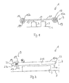
- the driver 19 divides the cavity in the interior of a tube 15a into a first cavity section 21a and a second cavity section 21b. It lies, how from the Fig. 2 and 3 it can be seen, the second cavity portion 21b viewed in the conveying direction I behind the first cavity portion 21 a. Both cavity portions 21 a, 21 b of a pipe 15 a are connected to a supply / discharge line 23 for hydraulic fluid, via the hydraulic fluid and can be discharged.
- Each tube 15a thus forms a double-acting hydraulic cylinder whose piston is formed by the driver 19.
- everyone is the two drivers 19 coupled via a magnetic field with the carriage 11 such that the carriage 11 is taken away by the drivers 19 and thus driven when the drivers 19 are moved along the tubes 15 a.
- the magnetic field can be generated, for example, by arranging permanent magnets on each driver 19 and on the carriage 11, in particular in the region of the sliding sleeves 19, which generate a sufficiently strong magnetic field by which the carriage 11 can be pulled along by the drivers 19.
- the cavity portions 21a, 21b of each tube 15a are filled with hydraulic fluid, which can be supplied via the supply / discharge lines 23.
- the inflow / outflow 23 of the cavity portion 23a may be connected to the inflow / outflow 23 of the cavity portion 21b of the same tube 15a via a hydraulic line 25, so that hydraulic fluid is connected through an interposed pump 27 between the cavity portions 21a, 21b of the same tube 15a can be pumped back and forth.
- the hydraulic line 25 and the pump 27 are in Fig. 3 shown by way of example for one of the two tubes 15a.
- the drivers 19 in the two tubes 15a are thereby moved in the conveying direction I, that in each tube 15a hydraulic fluid from the second cavity portion 21b is pumped into the first cavity portion 21a. Due to the magnetic coupling of the carriage 11 is pulled along by the drivers 19, so that the carriage 11 and thus the product holder 13 also move in the conveying direction I. In order to move the drivers 19 and thus the carriage 11 and the product holder 19 counter to the conveying direction I, the hydraulic fluid in each tube 19 is pumped in the reverse direction from the first cavity portion 21a into the second cavity portion 21b.
- a controller In order to adjust the position of the driver 19 or to drive off a respective desired movement profile along the respective tube 15a, a controller, not shown, may be provided, which is coupled, for example, with sensors in order to determine the instantaneous position of the driver 19. The controller can then control the pump 27 such that the driver 19 is moved according to a desired speed or movement profile. The controller can thus implement the product supply in a conventional manner according to the particular application.
- the carriage 11 and the product holder 13 may be provided for conveying the products 3.
- the product support 5 can also be formed by an endless conveyor belt with which the products 3 are conveyed.
- the carriage 11 and the product holder 13 may be provided, in particular, to move the remaining, not cut ends of the products 3 away from the conveying direction I of the cutting blade 7 after the slicing process and to supply them to a residual container.
- the carriage 11 is coupled to a linear drive which comprises a linear electromagnetic motor which has a stator 29 extending along the conveying direction I and a rotor 31 movable along the stator 29, which is designed as part of the carriage 11.
- a linear drive which comprises a linear electromagnetic motor which has a stator 29 extending along the conveying direction I and a rotor 31 movable along the stator 29, which is designed as part of the carriage 11.
- the rotor 31 is arranged at a transverse to the conveying direction I end of the carriage 11.
- a sliding sleeve 33 is arranged around a tubular guide 35, by means of which the carriage 11 is guided along the conveying direction I.
- the rotor 31 includes permanent magnets, not shown.
- electric coils are arranged, through which a magnetic field can be generated, which interacts with the magnetic field of the permanent magnets of the rotor 31 such that the rotor 31 along the conveying direction I can be moved.
- a magnetic field traveling along the stator 29 can be generated by the coils, through which the rotor 31 is entrained.
- the carriage 11 can be moved in the conveying direction I or counter to the conveying direction I, depending on the energization of the coils. In addition, it is possible to keep the carriage 11 at a certain position along the conveying direction I.
- the stator 29 may comprise permanent magnets and the rotor 31 may comprise energizable coils by means of which a magnetic field can be generated which interacts with the permanent magnets such that the rotor 31 can be moved along the conveying direction I.
- a further guide can also be provided on the side of the feed device 9, along which the stator 29 extends, so that the carriage 11 can be guided on both sides.
- a further electromagnetic linear motor having a stator extending along the conveying direction I and a rotor formed as part of the carriage 11 may be provided (not shown). The carriage 11 can therefore also be driven at its two transverse to the conveying direction I ends by means of a respective electromagnetic linear motor.
Description
Die vorliegende Erfindung betrifft eine Vorrichtung zum Aufschneiden von Lebensmittelprodukten, insbesondere Wurst, Fleisch oder Käse gemäß Oberbegriff des Patentanspruchs 1. Weiter betrifft die Erfindung eine Zuführeinrichtung gemäß Oberbegriff des Patentanspruchs 12.The present invention relates to a device for slicing food products, in particular sausage, meat or cheese according to the preamble of claim 1. Furthermore, the invention relates to a feeder according to the preamble of claim 12.
Vorrichtungen zum Aufschneiden von Lebensmittelprodukten werden auch als Aufschneidemaschinen oder Slicer bezeichnet. Bei bekannten Vorrichtungen mit einer Zuführeinrichtung, mit der wenigstens ein Produkt in einer Förderrichtung gefördert und einem der Zuführeinrichtung nachgeordneten Schneidmesser zugeführt werden kann, wobei die Zuführeinrichtung zumindest einen Schlitten aufweist, an dem wenigstens ein mit dem Produkt zusammenwirkender Produkthalter angeordnet ist, und wobei der Schlitten längs der Förderrichtung bewegbar ist, ist der Antrieb der Zuführeinrichtung als Spindel ausgebildet, die rotierend antreibbar ist. Bei der Spindel handelt es sich somit um einen rotierenden Antrieb für den Schlitten. Dabei ist der Schlitten mittels einer auf der Spindel aufgefädelten Mutter mit der Spindel gekoppelt, so dass die rotierende Bewegung der Spindel in eine translatorische Bewegung des Schlittens umgesetzt und der Schlitten längs der Förderrichtung verfahren werden kann. Der über die Spindel realisierte Antrieb für den Schlitten ist relativ aufwändig, auch hinsichtlich der zum Schutz bzw. der Reinigung der Spindel erforderlichen Maßnahmen.Devices for slicing food products are also referred to as slicers or slicers. In known devices with a feed device, with which at least one product can be conveyed in a conveying direction and fed to a feed device downstream cutting blade, wherein the feed device has at least one carriage on which at least one product holder cooperating with the product is arranged, and wherein the carriage along the conveying direction is movable, the drive of the feed device is designed as a spindle which is driven in rotation. The spindle is thus a rotating drive for the slide. In this case, the carriage is coupled by means of a threaded on the spindle nut with the spindle, so that the rotating movement of the spindle can be converted into a translational movement of the carriage and the carriage can be moved along the conveying direction. The realized via the spindle drive for the carriage is relatively complex, also in terms of the protection or cleaning of the spindle required measures.
Die DE
Der vorliegenden Erfindung liegt die Aufgabe zu Grunde, eine verbesserte Zuführeinrichtung zu schaffen, die mit geringem Aufwand realisierbar ist und mittels der auf einfache und zuverlässige Weise der Schlitten angetrieben werden kann.The present invention is based on the object to provide an improved feeding, which can be realized with little effort and by means of which the carriage can be driven in a simple and reliable manner.
Die Aufgabe wird durch eine Vorrichtung mit den Merkmalen des Anspruchs 1 gelöst.The object is achieved by a device having the features of claim 1.
Bei der erfindungsgemäßen Vorrichtung wird der Schlitten durch einen Linearantrieb angetrieben. Dieser kann gegenüber einem Spindelantrieb einfacher in die Aufschneidevorrichtung integriert werden. Zudem verschmutzt der Linearantrieb im Vergleich zum Spindelantrieb weniger stark bzw. der Linearantrieb lässt sich einfacher reinigen.
Vorteilhaft ist ferner, dass der Linearantrieb direkt eine lineare Antriebsbewegung für den Schlitten erzeugt, so dass es nicht - wie bei einer Spindel - erforderlich ist, eine Drehbewegung in eine lineare Bewegung für den Schlitten umzusetzen. Gleichwohl erlaubt auch der Linearantrieb die Übertragung ausreichend großer Kräfte und die Ausführung hochpräziser und reproduzierbarer Zuführbewegungen.In the apparatus according to the invention, the carriage is driven by a linear drive. This can be easily integrated into the slicing device compared to a spindle drive. In addition, the linear drive contaminates less than the spindle drive or the linear drive is easier to clean.
It is also advantageous that the linear drive directly generates a linear drive movement for the carriage, so that it is not necessary - as in a spindle - to implement a rotational movement in a linear movement for the carriage. Nevertheless, the linear drive allows the transmission of sufficiently large forces and the execution of high-precision and reproducible feed movements.
Bei einer nicht erfindungsgemäßen Variante weist der Linearantrieb einen elektromagnetischen Linearmotor mit einem längs der Förderrichtung verlaufenden Stator und einem entlang des Stators verfahrbaren Läufer auf, welcher von dem Schlitten gebildet ist. Derartige elektromagnetische Linearmotoren werden auch als Wanderfeldmotoren bezeichnet.In a variant not according to the invention, the linear drive has an electromagnetic linear motor with a stator extending along the conveying direction and a rotor movable along the stator, which rotor is formed by the carriage. Such electromagnetic linear motors are also referred to as traveling-field motors.
Durch einen elektromagnetischen Linearmotor kann der Linearantrieb besonders einfach und verhältnismäßig kostengünstig realisiert werden. Außerdem lassen sich derartige Linearmotoren auf elektrischem Wege einfach betreiben und steuern. Insbesondere eine exakte Ansteuerung und Verstellung des Linearmotors kann beispielsweise mittels einer, insbesondere digitalen, Steuerung und/oder Regelung einfach realisiert werden.By an electromagnetic linear motor, the linear drive can be realized in a particularly simple and relatively inexpensive. In addition, such linear motors can be easily operated and controlled by electrical means. In particular, an exact control and adjustment of the linear motor can be easily realized for example by means of a, in particular digital, control and / or regulation.
Bevorzugt umfasst der Schlitten bei der nicht erfindungsgemäßen Variante zumindest einen Magneten, insbesondere Permanentmagneten, und am Stator ist zumindest eine bestrombare Spule zur Erzeugung eines mit dem Magneten wechselwirkenden Magnetfelds vorgesehen, durch das der Schlitten entlang des Stators bewegt werden kann. Das Magnetfeld kann beispielweise derart erzeugt werden, dass es sich entlang des Stators fortbewegt und dabei - in an sich bei einem elektromagnetischen Linearmotor bekannter Weise - den magnetischen Schlitten mit sich zieht. An am Schlitten vorgesehenen Permanentmagneten ist insbesondere vorteilhaft, dass keine elektrischen Stromleitungen zum Schlitten geführt werden müssen, die demzufolge beim Verfahren des Schlittens auch nicht mitgeführt werden müssen.In the variant not according to the invention, the carriage preferably comprises at least one magnet, in particular permanent magnets, and at least one energizable coil for generating a magnetic field interacting with the magnet is provided on the stator, by means of which the carriage can be moved along the stator. The magnetic field can be generated, for example, so that it moves along the stator and thereby - in itself in an electromagnetic linear motor known manner - pulls the magnetic slide with it. At permanent magnets provided on the slide is particularly advantageous that no electrical power lines must be guided to the carriage, which therefore also do not have to be carried during the process of the carriage.
Nach einer weiteren Ausgestaltung der nicht erfindungsgemäßen Variante umfasst der Schlitten zumindest eine bestrombare Spule und entlang des Stators können Magnete, insbesondere Permanentmagnete, angeordnet sein, die mit dem von der Spule erzeugbaren Magnetfeld derart zusammenwirken, dass der Schlitten entlang des Stators bewegt werden kann. Bei dieser Ausgestaltung ist es somit erforderlich, dass die Spule des Schlittens bestromt wird, während die Magnete des Stators unbestromt sein können.According to a further embodiment of the variant not according to the invention, the carriage comprises at least one energizable coil and along the stator magnets, in particular permanent magnets, can be arranged, which cooperate with the magnetic field generated by the coil such that the carriage can be moved along the stator. In this embodiment, it is thus necessary that the coil of the carriage is energized, while the magnets of the stator can be energized.
Erfindungsgemäß weist der Linearantrieb wenigstens einen längs der Förderrichtung bewegbaren Mitnehmer auf, der berührungslos mit dem Schlitten derart gekoppelt ist, dass der Schlitten einer Bewegung des Mitnehmers längs der Förderrichtung folgt.According to the invention, the linear drive has at least one driver which can be moved along the conveying direction and which is coupled in a non-contact manner to the carriage such that the carriage follows a movement of the driver along the conveying direction.
Erfindungsgemäß ist der Mitnehmer über zumindest ein, insbesondere permanentes, Magnetfeld mit dem Schlitten gekoppelt. Die berührungslose Kopplung zwischen dem Mitnehmer und dem Schlitten kann besonders einfach mittels des Magnetfelds realisiert werden. Dabei lassen sich auch starke Magnetfelder relativ einfach erzeugen.According to the invention, the driver is coupled to the carriage via at least one, in particular permanent, magnetic field. The contactless coupling between the driver and the carriage can be realized particularly easily by means of the magnetic field. It is also possible to generate strong magnetic fields relatively easily.
Besonders bevorzugt umfassen der Mitnehmer und/oder der Schlitten jeweils zumindest einen Magneten, insbesondere einen Permanentmagneten. Zum Beispiel durch einen am Mitnehmer angebrachten oder den Mitnehmer bildenden Magneten und einem am Schlitten angebrachten Gegenmagneten kann das Magnetfeld zur Kopplung des Mitnehmers mit dem Schlitten besonders einfach erzeugt werden. Die Verwendung von Permanentmagneten hat insbesondere den Vorteil, dass diese kostengünstig und störungsunanfällig sind und damit ein dauerhaftes Magnetfeld erzeugt werden kann.Particularly preferably, the driver and / or the carriage each comprise at least one magnet, in particular a permanent magnet. For example, by a magnet attached to the driver or forming the driver and a counter-magnet mounted on the slide, the magnetic field for coupling the driver to the slide can be generated particularly easily. The use of permanent magnets has the particular advantage that they are inexpensive and trouble-prone and thus a permanent magnetic field can be generated.
Nach einer bevorzugten Weiterbildung der Erfindung umfasst der Linearantrieb zumindest einen doppeltwirkenden Hydraulikzylinder, dessen Kolben von dem Mitnehmer gebildet ist und wobei der Schlitten längs der Hydraulikzylinders bewegt werden kann. Der Mitnehmer ist somit innerhalb des Hydraulikzylinders angeordnet und aufgrund der Doppelwirkung des Hydraulikzylinders von beiden Seiten mit Hydraulikflüssigkeit beaufschlagbar. Dadurch kann die Position des Mitnehmers sowohl in Förderrichtung als auch entgegen der Förderrichtung mittels der im Hydraulikzylinder vorhandenen Hydraulikflüssigkeit mit hoher Genauigkeit eingestellt werden.According to a preferred embodiment of the invention, the linear drive comprises at least one double-acting hydraulic cylinder whose piston is formed by the driver and wherein the carriage can be moved along the hydraulic cylinder. The driver is thus arranged within the hydraulic cylinder and can be acted upon by hydraulic fluid from both sides due to the double action of the hydraulic cylinder. Thereby, the position of the driver can be adjusted both in the conveying direction and against the conveying direction by means of hydraulic fluid present in the hydraulic cylinder with high accuracy.
Ein Hydraulikzylinder ist vorteilhaft, da aufgrund der geringen Kompressibilität der Hydraulikflüssigkeit die Position des Mitnehmers längs des Hydraulikzylinders mit extrem hoher Genauigkeit eingestellt werden kann, so dass jedes gewünschte Bewegungsprofil für den Schlitten mit hoher Genauigkeit realisiert werden kann. Außerdem können mittels der Hydraulikflüssigkeit auch vergleichsweise hohe Kräfte auf den Mitnehmer übertragen werden.A hydraulic cylinder is advantageous because, due to the low compressibility of the hydraulic fluid, the position of the driver along the hydraulic cylinder can be adjusted with extremely high accuracy, so that any desired motion profile for the slide can be realized with high accuracy. In addition, comparatively high forces can be transmitted to the driver by means of the hydraulic fluid.
Nach einer bevorzugten Ausgestaltung der Erfindung ist der Mitnehmer in einem längs der Förderrichtung verlaufenden, insbesondere zylinderförmigen, Hohlraum angeordnet. Wie vorstehend erwähnt wurde, ist bei aus dem Stand der Technik bekannten Vorrichtungen eine Spindel als Antrieb für den Schlitten vorgesehen. Dabei ist es insbesondere aus hygienischen Gründen und zum Schutz der Spindel vor Verschmutzung erforderlich, dass die Spindel in einem Gehäuse untergebracht ist. Demgegenüber kann durch die erfindungsgemäße Anordnung des Mitnehmers in dem Hohlraum ein zusätzliches Gehäuse entfallen. Entsprechendes gilt für den vorstehend genannten Hydraulikzylinder. Dadurch verringert sich der Herstellungsaufwand für die Vorrichtung. Außerdem kann die Vorrichtung kompakter gebaut werden, da an der Vorrichtung kein zusätzlicher Bauraum für ein Gehäuse vorgesehen werden muss.According to a preferred embodiment of the invention, the driver is arranged in a longitudinal direction of the conveying direction, in particular cylindrical, cavity. As mentioned above, in prior art devices, a spindle is provided to drive the carriage. It is necessary in particular for reasons of hygiene and to protect the spindle from contamination that the spindle is housed in a housing. In contrast, can account for an additional housing by the inventive arrangement of the driver in the cavity. The same applies to the above-mentioned hydraulic cylinder. This reduces the manufacturing cost of the device. In addition, the device can be made more compact, since no additional space for a housing must be provided on the device.
Nach einer Weiterbildung der Erfindung unterteilt der Mitnehmer den Hohlraum in einen ersten Hohlraumabschnitt und einen zweiten Hohlraumabschnitt, der in Förderrichtung betrachtet hinter dem ersten Hohlraumabschnitt liegt, wobei zumindest ein Hohlraumabschnitt mit Hydraulikflüssigkeit beaufschlagbar ist, um den Mitnehmer zu bewegen. Der Hohlraumabschnitt kann somit beispielsweise nach Art eines einfachwirkenden oder eines doppeltwirkenden Hydraulikzylinders ausgestaltet sein, so dass der Mitnehmer mittels Hydraulikflüssigkeit längs der Förderrichtung bewegbar ist.According to a development of the invention, the driver divides the cavity into a first cavity section and a second cavity section, which, viewed in the conveying direction, lies behind the first cavity section, wherein at least one cavity section can be acted upon by hydraulic fluid in order to move the driver. The cavity section can thus be designed, for example, in the manner of a single-acting or a double-acting hydraulic cylinder, so that the driver can be moved along the conveying direction by means of hydraulic fluid.
Vorzugsweise sind beide Hohlraumabschnitte mit Hydraulikflüssigkeit gefüllt und jeweils mit einer Zu-/Ableitung für Hydraulikflüssigkeit verbunden, mittels der Hydraulikflüssigkeit in den jeweiligen Hohlraumabschnitt geleitet oder aus dem jeweiligen Hohlraumabschnitt entnommen werden kann.Preferably, both cavity sections are filled with hydraulic fluid and in each case connected to a supply / discharge line for hydraulic fluid, can be directed by means of the hydraulic fluid into the respective cavity section or removed from the respective cavity section.
Bei der Hydraulikflüssigkeit kann es sich um lebensmitteltaugliches Öl oder Wasser handeln.The hydraulic fluid may be food grade oil or water.
Bevorzugt ist der Linearantrieb gleichzeitig als Führung für den Schlitten ausgebildet. Antrieb und Führung verschmelzen so zu einer Einheit, so dass die Aufschneidevorrichtung kompakter gebaut werden kann.Preferably, the linear drive is at the same time designed as a guide for the carriage. Drive and guide merge into a single unit so that the slicing device can be made more compact.
Die Führung kann ein Rohr umfassen, dessen Längsachse in Förderrichtung verläuft.The guide may comprise a tube whose longitudinal axis extends in the conveying direction.
Bei einer bevorzugten Weiterbildung der Erfindung weist der Schlitten eine Hülse, insbesondere eine Gleithülse, auf, mittels welcher der Schlitten an dem Rohr beweglich angeordnet ist, wobei die Hülse das Rohr umgibt und der Mitnehmer innerhalb des Rohres angeordnet ist.In a preferred embodiment of the invention, the carriage on a sleeve, in particular a sliding sleeve, on, by means of which the carriage is movably disposed on the tube, wherein the sleeve surrounds the tube and the driver is disposed within the tube.
Es kann eine Steuerung vorgesehen sein, mittels der die Position des Schlittens einstellbar und/oder ein vorgegebenes Bewegungs- oder Geschwindigkeitsprofil für den Schlitten längs der Förderrichtung realisierbar ist. Die Steuerung kann mit der eigentlichen Steuerung der Aufschneidevorrichtung gekoppelt oder in diese integriert sein.A control may be provided by means of which the position of the carriage can be adjusted and / or a predetermined movement or speed profile for the carriage along the conveying direction can be realized. The controller may be coupled to or integrated with the actual control of the slicing apparatus.
Das Produkt kann mittels des Schlittens in der Förderrichtung gefördert werden. Die Zuführeinrichtung kann auch ein an sich bekanntes Endlosförderband aufweisen, auf dem das Produkt aufliegt und mit dem das Produkt gefördert wird. Der Schlitten und der Produkthalter können somit zum Beispiel mit dem Produkt mitbewegt bzw. mitgefahren werden, ohne dass das Produkt durch den Schlitten bzw. den Produkthalter gefördert wird, um beispielsweise erst gegen Ende des Aufschneidevorgangs den Produkthalter mit dem Produkt in Eingriff zu bringen.The product can be conveyed by means of the carriage in the conveying direction. The feeder may also comprise a per se known endless conveyor belt on which the product rests and with the Product is promoted. The carriage and the product holder can thus be moved along with the product, for example, without the product being conveyed through the carriage or the product holder in order, for example, to bring the product holder into engagement with the product only towards the end of the slicing process.
Der Begriff "Produkthalter" ist breit auszulegen. Es kann sich dabei nicht nur um eine Einrichtung handeln, die das Produkt hält. Vielmehr kann darunter auch eine Einrichtung verstanden werden, die irgendwie mit dem Produkt in Kontakt gebracht und/oder mittels der das Produkt - wie auch immer - gehandhabt werden kann. Der Produkthalter kann beispielsweise ein Produktschieber oder ein Produktniederhalter sein.The term "product holder" is to be interpreted broadly. It can not just be a device that holds the product. Rather, it can also be understood as meaning a device which can somehow be brought into contact with the product and / or by means of which the product can be handled - however it may be. The product holder may be, for example, a product pusher or a product depressor.
Der Produkthalter kann auch als Produktgreifer ausgestaltet sein, der zumindest eine Greifklaue aufweist, welche insbesondere in das hintere, vom Schneidmesser abgewandte Ende des Produkts eingreifen kann. Aufgrund des Eingriffs in das Produkt kann dieses nicht nur in Förderrichtung, sondern auch entgegen der Förderrichtung vom Produkthalter bewegt werden. Beispielsweise kann der Schlitten mit dem als Produktgreifer ausgebildeten Produkthalter dazu vorgesehen sein, das nicht aufgeschnittene hintere Produktende im Anschluss an den Aufschneidevorgang vom Schneidmesser wegzubewegen, also entgegen der Förderrichtung zu bewegen, um diesen Produktrest anschließend in einen Restebehälter abzuwerfen.The product holder can also be designed as a product gripper, which has at least one gripping jaw, which can engage in particular in the rear, remote from the cutting blade end of the product. Due to the intervention in the product this can be moved not only in the conveying direction, but also against the conveying direction of the product holder. For example, the carriage with the product holder designed as a product gripper may be provided for moving the uncut rear end of the product away from the cutting blade following the slicing process, ie moving it counter to the conveying direction in order to then dump this product residue into a residual container.
Die Erfindung betrifft auch eine Zuführeinrichtung für eine Vorrichtung zum Aufschneiden von Lebensmittelprodukten. Die Zuführeinrichtung ist im Anspruch 12 definiert.The invention also relates to a feeding device for a device for slicing food products. The feeder is defined in claim 12.
Die Erfindung wird nachfolgend beispielhaft anhand der beiliegenden Zeichnungen beschrieben. Es zeigen, jeweils in schematischer Darstellung,
- Fig. 1
- eine hintere Ansicht einer erfindungsgemäßen Vorrichtung zum Aufschneiden von Lebensmittelprodukten,
- Fig. 2
- eine seitliche Ansicht der Vorrichtung von
Fig. 1 , - Fig. 3
- eine obere Ansicht der Vorrichtung von
Fig. 1 , - Fig. 4
- eine perspektivische, teilgeschnittene Ansicht einer Zuführeinrichtung der Vorrichtung von
Fig. 1 , und - Fig. 5
- eine obere Ansicht einer nicht-erfindungsgemäßen Vorrichtung zum Aufschneiden von Lebensmittelprodukten.
- Fig. 1
- a rear view of an apparatus according to the invention for slicing food products,
- Fig. 2
- a side view of the device of
Fig. 1 . - Fig. 3
- an upper view of the device of
Fig. 1 . - Fig. 4
- a perspective, partially sectioned view of a feeder of the device of
Fig. 1 , and - Fig. 5
- an upper view of a non-inventive device for slicing food products.
Die in den
Die Zuführeinrichtung 9 weist zudem zwei in Förderrichtung I verlaufende Führungen 15 auf, mittels welcher der Schlitten 11 längs der Förderrichtung I geführt ist. Dabei weist jede Führung 15 ein Rohr 15a auf, dessen Längsachse in Förderrichtung I verläuft. Der Schlitten 11 ist mittels jeweils einer Gleithülse 17 an jedem Rohr 15a angeordnet, so dass der Schlitten 11 entlang der Rohre 15a gleiten und somit längs der Förderrichtung I verfahren werden kann.The
Der Schlitten 11 kann dabei durch einen Linearantrieb angetrieben werden, der bei der Vorrichtung 1 folgendermaßen ausgestaltet ist. Der Linearantrieb weist Mitnehmer 19 auf, wobei jeweils ein Mitnehmer 19 im Inneren eines Rohres 15a angeordnet und längs des vom dem jeweiligen Rohr 15a gebildeten Hohlraums bewegbar ist. Dabei ist jeder Mitnehmer 19 mit dem Schlitten 11 über ein Magnetfeld derart gekoppelt ist, dass der Schlitten 11 der Bewegung des Mitnehmers 19 folgt.The
Insbesondere unterteilt der Mitnehmer 19 den Hohlraum im Inneren eines Rohres 15a in einen ersten Hohlraumabschnitt 21 a und einen zweiten Hohlraumabschnitt 21b. Dabei liegt, wie aus den
Jedes Rohr 15a bildet somit einen doppeltwirkenden Hydraulikzylinder, dessen Kolben von dem Mitnehmer 19 gebildet ist. Wie erwähnt, ist jeder der beiden Mitnehmer 19 über ein Magnetfeld mit dem Schlitten 11 derart gekoppelt, dass der Schlitten 11 von den Mitnehmern 19 mitgenommen und somit angetrieben wird, wenn die Mitnehmer 19 längs der Rohre 15a bewegt werden. Das Magnetfeld kann beispielsweise dadurch erzeugt werden, dass an jedem Mitnehmer 19 und am Schlitten 11, insbesondere im Bereich der Gleithülsen 19, Permanentmagnete angeordnet sind, die ein ausreichend starkes Magnetfeld erzeugen, durch das der Schlitten 11 von den Mitnehmern 19 mitgezogen werden kann.Each
Wie vorstehend erwähnt, sind die Hohlraumabschnitte 21a, 21b jedes Rohres 15a mit Hydraulikflüssigkeit gefüllt, die über die Zu-/Ableitungen 23 zugeführt bzw. abgeleitet werden kann. Dabei kann zum Beispiel die Zu-/Ableitung 23 des Hohlraumabschnitts 23a über eine Hydraulikleitung 25 mit der Zu-/Ableitung 23 des Hohlraumabschnitts 21b desselben Rohres 15a verbunden sein, so dass Hydraulikflüssigkeit über eine dazwischengeschaltete Pumpe 27 zwischen den Hohlraumabschnitten 21a, 21b desselben Rohrs 15a hin- und her gepumpt werden kann. Die Hydraulikleitung 25 und die Pumpe 27 sind in
In Betrieb werden die Mitnehmer 19 in den beiden Rohren 15a dadurch in Förderrichtung I bewegt, dass in jedem Rohr 15a Hydraulikflüssigkeit aus dem zweiten Hohlraumabschnitt 21b in den ersten Hohlraumabschnitt 21a gepumpt wird. Aufgrund der magnetischen Kopplung wird der Schlitten 11 von den Mitnehmern 19 mitgezogen, so dass sich der Schlitten 11 und damit die Produkthalter 13 ebenfalls in Förderrichtung I bewegen. Um die Mitnehmer 19 und damit den Schlitten 11 und die Produkthalter 19 entgegen der Förderrichtung I zu bewegen, wird in jedem Rohr 19 die Hydraulikflüssigkeit in der umgekehrten Richtung aus dem ersten Hohlraumabschnitt 21a in den zweiten Hohlraumabschnitt 21b gepumpt.In operation, the
Zur Einstellung der Position des Mitnehmers 19 bzw. zum Abfahren eines jeweils gewünschten Bewegungsprofils längs des jeweiligen Rohrs 15a kann eine nicht gezeigte Steuerung vorgesehen sein, die beispielsweise mit Sensoren gekoppelt ist, um jeweils die momentane Position des Mitnehmers 19 zu ermitteln. Die Steuerung kann dann die Pumpe 27 derart ansteuern, dass der Mitnehmer 19 gemäß einem gewünschten Geschwindigkeits- bzw. Bewegungsprofil verfahren wird. Die Steuerung kann insofern in herkömmlicher Weise gemäß der jeweiligen Anwendung die Produktzufuhr realisieren.In order to adjust the position of the
Der Schlitten 11 und die Produkthalter 13 können zur Förderung der Produkte 3 vorgesehen sein. Die Produktauflage 5 kann jedoch auch von einem Endlosförderband gebildet werden, mit dem die Produkte 3 gefördert werden. In diesem Falle können der Schlitten 11 und die Produkthalter 13 insbesondere dazu vorgesehen sein, nach dem Aufschneidevorgang die übrigbleibenden, nicht aufgeschnittenen Enden der Produkte 3 entgegen der Förderrichtung I von Schneidmesser 7 wegzubewegen und diese einem Restebehälter zuzuführen.The
Die in
Bei der Vorrichtung 1' ist der Läufer 31 an einem quer zur Förderrichtung I liegenden Ende des Schlittens 11 angeordnet. An dem gegenüberliegenden Ende des Schlittens 11 ist eine Gleithülse 33 um eine rohrförmige Führung 35 angeordnet, mittels der der Schlitten 11 längs der Förderrichtung I geführt ist.In the device 1 ', the rotor 31 is arranged at a transverse to the conveying direction I end of the
Der Läufer 31 umfasst nicht dargestellte Permanentmagnete. Entlang des Stators 29 sind ebenfalls nicht dargestellte elektrische Spulen angeordnet, durch die ein Magnetfeld erzeugt werden kann, das mit dem Magnetfeld der Permanentmagnete des Läufers 31 derart wechselwirkt, dass der Läufer 31 längs der Förderrichtung I bewegt werden kann. Insbesondere kann durch die Spulen ein entlang des Stators 29 wanderndes Magnetfeld erzeugt werden, durch das der Läufer 31 mitgezogen wird. Dabei kann der Schlitten 11 je nach Bestromung der Spulen in Förderrichtung I oder entgegen der Förderrichtung I bewegt werden. Außerdem ist es möglich, den Schlitten 11 an einer bestimmten Position längs der Förderrichtung I zu halten.The rotor 31 includes permanent magnets, not shown. Along the
Es sind auch alternative Abwandlungen der vorstehend beschriebenen Vorrichtung 1' ohne weiteres möglich. Beispielsweise kann der Stator 29 Permanentmagnete und der Läufer 31 kann bestrombare Spulen aufweisen, mittels denen ein Magnetfeld erzeugt werden kann, das mit den Permanentmagneten derart zusammenwirkt, dass der Läufer 31 längs der Förderrichtung I verfahren werden kann.Alternative modifications of the apparatus 1 'described above are also readily possible. For example, the
Außerdem kann eine weitere Führung auch auf derjenigen Seite der Zuführeinrichtung 9 vorgesehen sein, längs der der Stator 29 verläuft, so dass der Schlitten 11 beidseitig geführt sein kann. Entsprechend kann auch auf der Seite der in
Außerdem ist es möglich, dass die beiderseits des Schlittens 11 angeordneten Linearmotoren gleichzeitig zur Führung des Schlittens 11 dienen, so dass die in
- 1, 1'1, 1 '
- Vorrichtungcontraption
- 33
- Produktproduct
- 55
- Produktauflageproduct support
- 77
- Schneidmessercutting blade
- 99
- Zuführeinrichtungfeeding
- 1111
- Schlittencarriage
- 1313
- Produkthalterproduct holder
- 1515
- Führungguide
- 15a15a
- Rohrpipe
- 1717
- Gleithülsesliding sleeve
- 1919
- Mitnehmertakeaway
- 21a21a
- erster Hohlraumabschnittfirst cavity section
- 21b21b
- zweiter Hohlraumabschnittsecond cavity section
- 2323
- Zu-/AbleitungSupply / discharge
- 2525
- Hydraulikleitunghydraulic line
- 2727
- Pumpepump
- 2929
- Statorstator
- 3131
- Läuferrunner
- 3333
- Gleithülsesliding sleeve
- 3535
- Führungguide
Claims (12)
- An apparatus for slicing food products, in particular sausage, meat or cheese, comprising
a feed device (9) by which at least one product (3) can be conveyed in a conveying direction (1) and can be fed to a cutting blade (7) disposed downstream of the feed device (9),
wherein the feed device (9) has at least one carriage (11); and wherein the carriage (11) is movable along the conveying direction (I);
wherein the carriage (11) is coupled to a linear drive by means of which the carriage (11) is movable along the conveying direction (I), characterised in that
at least one product holder (13) cooperating with the product (3) is arranged at the carriage; and in that the linear drive has at least one driver (19) which can be moved along the conveying direction (I) and which is coupled to the carriage (11) via at least one magnetic field in a contactless manner such that the carriage (11) follows a movement of the driver (19) along the conveying direction (I). - An apparatus in accordance with claim 1,
characterised in that
the magnetic field is a permanent magnetic field. - An apparatus in accordance with claim 1 or claim 2,
characterised in that
the driver (19) and/or the carriage (11) each comprises/comprise at least one magnet, in particular a permanent magnet. - An apparatus in accordance with any one of the preceding claims,
characterised in that
the driver (19) and/or the carriage (11) is/are formed at least partly from magnetic material or from magnetisable material. - An apparatus in accordance with any one of the preceding claims,
characterised in that
the linear drive comprises a dual-action hydraulic cylinder whose piston is formed by the driver (19), with the carriage (11) being able to be moved along the hydraulic cylinder. - An apparatus in accordance with any one of the preceding claims,
characterised in that
the driver (19) is arranged in a hollow space (21a, 21b), in particular a cylindrical hollow space, extending along the conveying direction (I). - An apparatus in accordance with claim 6,
characterised in that
the driver (19) divides the hollow space into a first hollow space section (21a) and into a second hollow space section (21 b) which lies behind the first hollow space section (21 a) viewed in the conveying direction (I), with at least one hollow space section (21a, 21 b) being able to be acted on by hydraulic fluid to move the driver (19). - An apparatus in accordance with claim 7,
characterised in that
both hollow space sections (21a, 21 b) are filled with hydraulic fluid and are each connected to an inflow/outflow line (23) for hydraulic fluid by means of which hydraulic fluid can be conducted into the respective hollow space section (21a, 21 b) or can be removed from the respective hollow space section (21a, 21b). - An apparatus in accordance with at least one of the preceding claims,
characterised in that
the linear drive is simultaneously formed as a guide (15) for the carriage (11), with the guide (15) in particular comprising a pipe (15a) whose longitudinal axis extends in the conveying direction (I). - An apparatus in accordance with claim 9,
characterised in that
the carriage has a sleeve (17), in particular a sliding sleeve, by means of which the carriage (11) is movably arranged at the pipe (15a),
wherein the sleeve (17) surrounds the pipe (15a) and the driver (19) is arranged within the pipe (15a). - An apparatus in accordance with at least one of the preceding claims,
characterised in that
a control is provided by means of which the position of the carriage (11) and/or a predefined movement profile or speed profile for the carriage (11) along the conveying direction can be set or realized. - A feed device for an apparatus (1, 1') for slicing food products (3), wherein the feed device (9) has a carriage (11) which is movable along a conveying direction (I), with the carriage (11) being coupled to a linear drive by means of which the carriage (11) can be moved along the conveying direction (I),
characterised in that
at least one product holder (13) is arranged at the carriage (11) and can cooperate with a product (3), wherein the linear drive has at least one driver (19) which can be moved along the conveying direction (I) and which is coupled to the carriage (11) via at least one magnetic field in a contactless manner such that the carriage (11) follows a movement of the driver (19) along the conveying direction (I).
Applications Claiming Priority (2)
| Application Number | Priority Date | Filing Date | Title |
|---|---|---|---|
| DE102011106946 | 2011-07-08 | ||
| DE201110111601 DE102011111601A1 (en) | 2011-07-08 | 2011-08-25 | Device for slicing food products |
Publications (2)
| Publication Number | Publication Date |
|---|---|
| EP2543485A1 EP2543485A1 (en) | 2013-01-09 |
| EP2543485B1 true EP2543485B1 (en) | 2014-12-24 |
Family
ID=46456434
Family Applications (1)
| Application Number | Title | Priority Date | Filing Date |
|---|---|---|---|
| EP20120174954 Active EP2543485B1 (en) | 2011-07-08 | 2012-07-04 | Device for cutting a food product |
Country Status (2)
| Country | Link |
|---|---|
| EP (1) | EP2543485B1 (en) |
| DE (1) | DE102011111601A1 (en) |
Families Citing this family (3)
| Publication number | Priority date | Publication date | Assignee | Title |
|---|---|---|---|---|
| DE102013206162A1 (en) * | 2013-04-08 | 2014-10-09 | Weber Maschinenbau Gmbh Breidenbach | Traversing carriage for a linear guide |
| DE102014106353A1 (en) | 2014-05-07 | 2015-11-12 | Inauen Group Ag | cutting machine |
| DE102021101315A1 (en) * | 2021-01-22 | 2022-07-28 | Multivac Sepp Haggenmüller Se & Co. Kg | Multi-lane slicing machine with independently controllable grippers |
Family Cites Families (10)
| Publication number | Priority date | Publication date | Assignee | Title |
|---|---|---|---|---|
| US3776073A (en) * | 1970-10-30 | 1973-12-04 | Kraftco Corp | Method and apparatus for preparing cheese cuts |
| US4344341A (en) * | 1980-09-04 | 1982-08-17 | Lotz Walter E | Slicing apparatus |
| GB2099609B (en) * | 1981-06-02 | 1984-11-07 | Thurne Eng Co Ltd | Slicing machine |
| GB8314762D0 (en) * | 1983-05-27 | 1983-07-06 | Thurne Eng Co Ltd | Slicing machine |
| DE8334010U1 (en) * | 1983-11-26 | 1984-02-23 | Reifenhäuser, Toni, 5231 Burglahr | DEVICE FOR SLICING MEAT IN SLICE |
| US5989116A (en) * | 1998-02-03 | 1999-11-23 | Swift & Company, Inc. | High-speed bone-in loin slicer |
| JP4127738B2 (en) * | 1999-03-31 | 2008-07-30 | プリマハム株式会社 | Raw wood slicer for ham etc. |
| WO2007002819A2 (en) * | 2005-06-29 | 2007-01-04 | Premark Feg L.L.C. | Programmable slicer with powered food carriage |
| US7600459B2 (en) * | 2005-09-21 | 2009-10-13 | J. E. Grote Company, Inc. | Drive mechanism and slicing apparatus for food slicing machine |
| DE102009020633A1 (en) * | 2009-05-09 | 2010-11-11 | Bizerba Gmbh & Co. Kg | Slicer for e.g. meat, has circular knife driven for separating slices of food strand, and feed device feeding food strand by electric linear motor in driven manner and comprising feed arm, which is connected with rotor of linear motor |
-
2011
- 2011-08-25 DE DE201110111601 patent/DE102011111601A1/en not_active Withdrawn
-
2012
- 2012-07-04 EP EP20120174954 patent/EP2543485B1/en active Active
Also Published As
| Publication number | Publication date |
|---|---|
| DE102011111601A1 (en) | 2013-01-10 |
| EP2543485A1 (en) | 2013-01-09 |
Similar Documents
| Publication | Publication Date | Title |
|---|---|---|
| DE3601850A1 (en) | WIRE FEEDING, CUTTING AND STRIPING DEVICE | |
| EP3521219B1 (en) | Transport device and method for adapting a transport device | |
| EP2628392A1 (en) | Method and device for dividing products | |
| EP3034442B1 (en) | Device for transporting products | |
| WO2003028963A1 (en) | Device for slicing food products | |
| EP2543485B1 (en) | Device for cutting a food product | |
| DE102008044465B3 (en) | Profile cutter for even cutting of material strand to lengths, particularly plastic strand profile, has base frame, drive arranged at base frame, cam mechanism connected with drive and control unit for controlling drive | |
| WO2019096969A1 (en) | Pipe cutting machine with a controlled floating cutting mandrel, and cutting method | |
| DE102012102525B4 (en) | Multi-mode press drive for a press and method of operating a press drive | |
| EP2901860B1 (en) | Dough dividing machine | |
| DE102010008047A1 (en) | Apparatus i.e. slicer, for slicing e.g. food product, has cutting blade that is pivotable, where cutting blade remains aligned parallel to cutting plane or departs from parallel alignment | |
| EP2974970B1 (en) | Pushing device for filling packaging with blister packs | |
| EP2764963B1 (en) | Device for cutting products on three sides | |
| DE102009038875A1 (en) | drive motor | |
| EP3505355A1 (en) | Cutting device for continuous labels | |
| EP2281643B1 (en) | Assembly for bending tubular workpieces | |
| WO2020120587A1 (en) | Apparatus having an electric motor for providing packaging material and method for operating a packaging material-provisioning apparatus | |
| DE102020103085A1 (en) | SLICING DEVICE WITH BLANK CUT FUNCTION | |
| EP3124189B1 (en) | Slicing device | |
| CH699425B1 (en) | Device for cutting yarn in yarn cleaner that monitors and ensures quality of yarn in spinning and/or winding machine in textile industry, has gap formed such that magnetic field acting radially on solenoid plunger of drive is cancelled | |
| EP3233676B1 (en) | Moving device having an operating configuration and a maintenance configuration | |
| EP1613462A1 (en) | Molding device | |
| EP2420148A1 (en) | Cutting device of a string machine for the tobacco processing industry | |
| EP3487644A1 (en) | Drawing carriage for a drawing machine, and drawing machine | |
| DE102020111586A1 (en) | Device and method for slicing food products |
Legal Events
| Date | Code | Title | Description |
|---|---|---|---|
| PUAI | Public reference made under article 153(3) epc to a published international application that has entered the european phase |
Free format text: ORIGINAL CODE: 0009012 |
|
| AK | Designated contracting states |
Kind code of ref document: A1 Designated state(s): AL AT BE BG CH CY CZ DE DK EE ES FI FR GB GR HR HU IE IS IT LI LT LU LV MC MK MT NL NO PL PT RO RS SE SI SK SM TR |
|
| AX | Request for extension of the european patent |
Extension state: BA ME |
|
| 17P | Request for examination filed |
Effective date: 20130708 |
|
| RBV | Designated contracting states (corrected) |
Designated state(s): AL AT BE BG CH CY CZ DE DK EE ES FI FR GB GR HR HU IE IS IT LI LT LU LV MC MK MT NL NO PL PT RO RS SE SI SK SM TR |
|
| 17Q | First examination report despatched |
Effective date: 20131030 |
|
| RIC1 | Information provided on ipc code assigned before grant |
Ipc: B26D 7/06 20060101AFI20140102BHEP Ipc: B26D 7/00 20060101ALN20140102BHEP |
|
| RIC1 | Information provided on ipc code assigned before grant |
Ipc: B26D 7/00 20060101ALN20140108BHEP Ipc: B26D 7/06 20060101AFI20140108BHEP |
|
| GRAP | Despatch of communication of intention to grant a patent |
Free format text: ORIGINAL CODE: EPIDOSNIGR1 |
|
| INTG | Intention to grant announced |
Effective date: 20140411 |
|
| GRAS | Grant fee paid |
Free format text: ORIGINAL CODE: EPIDOSNIGR3 |
|
| GRAA | (expected) grant |
Free format text: ORIGINAL CODE: 0009210 |
|
| AK | Designated contracting states |
Kind code of ref document: B1 Designated state(s): AL AT BE BG CH CY CZ DE DK EE ES FI FR GB GR HR HU IE IS IT LI LT LU LV MC MK MT NL NO PL PT RO RS SE SI SK SM TR |
|
| REG | Reference to a national code |
Ref country code: GB Ref legal event code: FG4D Free format text: NOT ENGLISH |
|
| REG | Reference to a national code |
Ref country code: CH Ref legal event code: EP |
|
| REG | Reference to a national code |
Ref country code: IE Ref legal event code: FG4D Free format text: LANGUAGE OF EP DOCUMENT: GERMAN |
|
| REG | Reference to a national code |
Ref country code: AT Ref legal event code: REF Ref document number: 702900 Country of ref document: AT Kind code of ref document: T Effective date: 20150115 |
|
| REG | Reference to a national code |
Ref country code: DE Ref legal event code: R096 Ref document number: 502012001888 Country of ref document: DE Effective date: 20150212 |
|
| REG | Reference to a national code |
Ref country code: NL Ref legal event code: VDEP Effective date: 20141224 |
|
| PG25 | Lapsed in a contracting state [announced via postgrant information from national office to epo] |
Ref country code: FI Free format text: LAPSE BECAUSE OF FAILURE TO SUBMIT A TRANSLATION OF THE DESCRIPTION OR TO PAY THE FEE WITHIN THE PRESCRIBED TIME-LIMIT Effective date: 20141224 Ref country code: LT Free format text: LAPSE BECAUSE OF FAILURE TO SUBMIT A TRANSLATION OF THE DESCRIPTION OR TO PAY THE FEE WITHIN THE PRESCRIBED TIME-LIMIT Effective date: 20141224 Ref country code: NO Free format text: LAPSE BECAUSE OF FAILURE TO SUBMIT A TRANSLATION OF THE DESCRIPTION OR TO PAY THE FEE WITHIN THE PRESCRIBED TIME-LIMIT Effective date: 20150324 |
|
| REG | Reference to a national code |
Ref country code: LT Ref legal event code: MG4D |
|
| PG25 | Lapsed in a contracting state [announced via postgrant information from national office to epo] |
Ref country code: LV Free format text: LAPSE BECAUSE OF FAILURE TO SUBMIT A TRANSLATION OF THE DESCRIPTION OR TO PAY THE FEE WITHIN THE PRESCRIBED TIME-LIMIT Effective date: 20141224 Ref country code: SE Free format text: LAPSE BECAUSE OF FAILURE TO SUBMIT A TRANSLATION OF THE DESCRIPTION OR TO PAY THE FEE WITHIN THE PRESCRIBED TIME-LIMIT Effective date: 20141224 Ref country code: HR Free format text: LAPSE BECAUSE OF FAILURE TO SUBMIT A TRANSLATION OF THE DESCRIPTION OR TO PAY THE FEE WITHIN THE PRESCRIBED TIME-LIMIT Effective date: 20141224 Ref country code: RS Free format text: LAPSE BECAUSE OF FAILURE TO SUBMIT A TRANSLATION OF THE DESCRIPTION OR TO PAY THE FEE WITHIN THE PRESCRIBED TIME-LIMIT Effective date: 20141224 |
|
| PG25 | Lapsed in a contracting state [announced via postgrant information from national office to epo] |
Ref country code: NL Free format text: LAPSE BECAUSE OF FAILURE TO SUBMIT A TRANSLATION OF THE DESCRIPTION OR TO PAY THE FEE WITHIN THE PRESCRIBED TIME-LIMIT Effective date: 20141224 |
|
| PG25 | Lapsed in a contracting state [announced via postgrant information from national office to epo] |
Ref country code: EE Free format text: LAPSE BECAUSE OF FAILURE TO SUBMIT A TRANSLATION OF THE DESCRIPTION OR TO PAY THE FEE WITHIN THE PRESCRIBED TIME-LIMIT Effective date: 20141224 Ref country code: SK Free format text: LAPSE BECAUSE OF FAILURE TO SUBMIT A TRANSLATION OF THE DESCRIPTION OR TO PAY THE FEE WITHIN THE PRESCRIBED TIME-LIMIT Effective date: 20141224 Ref country code: RO Free format text: LAPSE BECAUSE OF FAILURE TO SUBMIT A TRANSLATION OF THE DESCRIPTION OR TO PAY THE FEE WITHIN THE PRESCRIBED TIME-LIMIT Effective date: 20141224 Ref country code: ES Free format text: LAPSE BECAUSE OF FAILURE TO SUBMIT A TRANSLATION OF THE DESCRIPTION OR TO PAY THE FEE WITHIN THE PRESCRIBED TIME-LIMIT Effective date: 20141224 Ref country code: CZ Free format text: LAPSE BECAUSE OF FAILURE TO SUBMIT A TRANSLATION OF THE DESCRIPTION OR TO PAY THE FEE WITHIN THE PRESCRIBED TIME-LIMIT Effective date: 20141224 |
|
| PG25 | Lapsed in a contracting state [announced via postgrant information from national office to epo] |
Ref country code: PL Free format text: LAPSE BECAUSE OF FAILURE TO SUBMIT A TRANSLATION OF THE DESCRIPTION OR TO PAY THE FEE WITHIN THE PRESCRIBED TIME-LIMIT Effective date: 20141224 Ref country code: IS Free format text: LAPSE BECAUSE OF FAILURE TO SUBMIT A TRANSLATION OF THE DESCRIPTION OR TO PAY THE FEE WITHIN THE PRESCRIBED TIME-LIMIT Effective date: 20150424 |
|
| REG | Reference to a national code |
Ref country code: DE Ref legal event code: R097 Ref document number: 502012001888 Country of ref document: DE |
|
| PG25 | Lapsed in a contracting state [announced via postgrant information from national office to epo] |
Ref country code: DK Free format text: LAPSE BECAUSE OF FAILURE TO SUBMIT A TRANSLATION OF THE DESCRIPTION OR TO PAY THE FEE WITHIN THE PRESCRIBED TIME-LIMIT Effective date: 20141224 |
|
| PLBE | No opposition filed within time limit |
Free format text: ORIGINAL CODE: 0009261 |
|
| STAA | Information on the status of an ep patent application or granted ep patent |
Free format text: STATUS: NO OPPOSITION FILED WITHIN TIME LIMIT |
|
| 26N | No opposition filed |
Effective date: 20150925 |
|
| PG25 | Lapsed in a contracting state [announced via postgrant information from national office to epo] |
Ref country code: IT Free format text: LAPSE BECAUSE OF FAILURE TO SUBMIT A TRANSLATION OF THE DESCRIPTION OR TO PAY THE FEE WITHIN THE PRESCRIBED TIME-LIMIT Effective date: 20141224 |
|
| PG25 | Lapsed in a contracting state [announced via postgrant information from national office to epo] |
Ref country code: MC Free format text: LAPSE BECAUSE OF FAILURE TO SUBMIT A TRANSLATION OF THE DESCRIPTION OR TO PAY THE FEE WITHIN THE PRESCRIBED TIME-LIMIT Effective date: 20141224 Ref country code: SI Free format text: LAPSE BECAUSE OF FAILURE TO SUBMIT A TRANSLATION OF THE DESCRIPTION OR TO PAY THE FEE WITHIN THE PRESCRIBED TIME-LIMIT Effective date: 20141224 |
|
| REG | Reference to a national code |
Ref country code: CH Ref legal event code: PL |
|
| PG25 | Lapsed in a contracting state [announced via postgrant information from national office to epo] |
Ref country code: LU Free format text: LAPSE BECAUSE OF FAILURE TO SUBMIT A TRANSLATION OF THE DESCRIPTION OR TO PAY THE FEE WITHIN THE PRESCRIBED TIME-LIMIT Effective date: 20150704 |
|
| REG | Reference to a national code |
Ref country code: IE Ref legal event code: MM4A |
|
| PG25 | Lapsed in a contracting state [announced via postgrant information from national office to epo] |
Ref country code: LI Free format text: LAPSE BECAUSE OF NON-PAYMENT OF DUE FEES Effective date: 20150731 Ref country code: CH Free format text: LAPSE BECAUSE OF NON-PAYMENT OF DUE FEES Effective date: 20150731 |
|
| REG | Reference to a national code |
Ref country code: FR Ref legal event code: ST Effective date: 20160331 |
|
| PG25 | Lapsed in a contracting state [announced via postgrant information from national office to epo] |
Ref country code: FR Free format text: LAPSE BECAUSE OF NON-PAYMENT OF DUE FEES Effective date: 20150731 |
|
| PG25 | Lapsed in a contracting state [announced via postgrant information from national office to epo] |
Ref country code: IE Free format text: LAPSE BECAUSE OF NON-PAYMENT OF DUE FEES Effective date: 20150704 |
|
| GBPC | Gb: european patent ceased through non-payment of renewal fee |
Effective date: 20160704 |
|
| PG25 | Lapsed in a contracting state [announced via postgrant information from national office to epo] |
Ref country code: MT Free format text: LAPSE BECAUSE OF FAILURE TO SUBMIT A TRANSLATION OF THE DESCRIPTION OR TO PAY THE FEE WITHIN THE PRESCRIBED TIME-LIMIT Effective date: 20141224 |
|
| PG25 | Lapsed in a contracting state [announced via postgrant information from national office to epo] |
Ref country code: GB Free format text: LAPSE BECAUSE OF NON-PAYMENT OF DUE FEES Effective date: 20160704 Ref country code: BG Free format text: LAPSE BECAUSE OF FAILURE TO SUBMIT A TRANSLATION OF THE DESCRIPTION OR TO PAY THE FEE WITHIN THE PRESCRIBED TIME-LIMIT Effective date: 20141224 Ref country code: SM Free format text: LAPSE BECAUSE OF FAILURE TO SUBMIT A TRANSLATION OF THE DESCRIPTION OR TO PAY THE FEE WITHIN THE PRESCRIBED TIME-LIMIT Effective date: 20141224 Ref country code: HU Free format text: LAPSE BECAUSE OF FAILURE TO SUBMIT A TRANSLATION OF THE DESCRIPTION OR TO PAY THE FEE WITHIN THE PRESCRIBED TIME-LIMIT; INVALID AB INITIO Effective date: 20120704 |
|
| PG25 | Lapsed in a contracting state [announced via postgrant information from national office to epo] |
Ref country code: CY Free format text: LAPSE BECAUSE OF FAILURE TO SUBMIT A TRANSLATION OF THE DESCRIPTION OR TO PAY THE FEE WITHIN THE PRESCRIBED TIME-LIMIT Effective date: 20141224 Ref country code: GR Free format text: LAPSE BECAUSE OF FAILURE TO SUBMIT A TRANSLATION OF THE DESCRIPTION OR TO PAY THE FEE WITHIN THE PRESCRIBED TIME-LIMIT Effective date: 20141224 |
|
| PG25 | Lapsed in a contracting state [announced via postgrant information from national office to epo] |
Ref country code: BE Free format text: LAPSE BECAUSE OF NON-PAYMENT OF DUE FEES Effective date: 20150731 |
|
| PG25 | Lapsed in a contracting state [announced via postgrant information from national office to epo] |
Ref country code: TR Free format text: LAPSE BECAUSE OF FAILURE TO SUBMIT A TRANSLATION OF THE DESCRIPTION OR TO PAY THE FEE WITHIN THE PRESCRIBED TIME-LIMIT Effective date: 20141224 |
|
| PG25 | Lapsed in a contracting state [announced via postgrant information from national office to epo] |
Ref country code: MK Free format text: LAPSE BECAUSE OF FAILURE TO SUBMIT A TRANSLATION OF THE DESCRIPTION OR TO PAY THE FEE WITHIN THE PRESCRIBED TIME-LIMIT Effective date: 20141224 |
|
| PG25 | Lapsed in a contracting state [announced via postgrant information from national office to epo] |
Ref country code: PT Free format text: LAPSE BECAUSE OF FAILURE TO SUBMIT A TRANSLATION OF THE DESCRIPTION OR TO PAY THE FEE WITHIN THE PRESCRIBED TIME-LIMIT Effective date: 20141224 |
|
| REG | Reference to a national code |
Ref country code: AT Ref legal event code: MM01 Ref document number: 702900 Country of ref document: AT Kind code of ref document: T Effective date: 20170704 |
|
| PG25 | Lapsed in a contracting state [announced via postgrant information from national office to epo] |
Ref country code: AL Free format text: LAPSE BECAUSE OF FAILURE TO SUBMIT A TRANSLATION OF THE DESCRIPTION OR TO PAY THE FEE WITHIN THE PRESCRIBED TIME-LIMIT Effective date: 20141224 |
|
| PG25 | Lapsed in a contracting state [announced via postgrant information from national office to epo] |
Ref country code: AT Free format text: LAPSE BECAUSE OF NON-PAYMENT OF DUE FEES Effective date: 20170704 |
|
| P01 | Opt-out of the competence of the unified patent court (upc) registered |
Effective date: 20230522 |
|
| PGFP | Annual fee paid to national office [announced via postgrant information from national office to epo] |
Ref country code: DE Payment date: 20230720 Year of fee payment: 12 |
|
| REG | Reference to a national code |
Ref country code: DE Ref legal event code: R081 Ref document number: 502012001888 Country of ref document: DE Owner name: WEBER FOOD TECHNOLOGY GMBH, DE Free format text: FORMER OWNER: WEBER MASCHINENBAU GMBH BREIDENBACH, 35236 BREIDENBACH, DE |