EP2543115B1 - Electrical connector - Google Patents
Electrical connector Download PDFInfo
- Publication number
- EP2543115B1 EP2543115B1 EP11707624.0A EP11707624A EP2543115B1 EP 2543115 B1 EP2543115 B1 EP 2543115B1 EP 11707624 A EP11707624 A EP 11707624A EP 2543115 B1 EP2543115 B1 EP 2543115B1
- Authority
- EP
- European Patent Office
- Prior art keywords
- connector
- sliding element
- sliding
- connector element
- electrical connector
- Prior art date
- Legal status (The legal status is an assumption and is not a legal conclusion. Google has not performed a legal analysis and makes no representation as to the accuracy of the status listed.)
- Active
Links
- 238000005096 rolling process Methods 0.000 claims description 14
- 230000008878 coupling Effects 0.000 claims description 5
- 238000010168 coupling process Methods 0.000 claims description 5
- 238000005859 coupling reaction Methods 0.000 claims description 5
- 239000000463 material Substances 0.000 description 4
- 229920003023 plastic Polymers 0.000 description 4
- 239000004033 plastic Substances 0.000 description 4
- 230000002093 peripheral effect Effects 0.000 description 2
- 239000004020 conductor Substances 0.000 description 1
- 238000010276 construction Methods 0.000 description 1
- 239000002184 metal Substances 0.000 description 1
- 230000000149 penetrating effect Effects 0.000 description 1
- 230000000750 progressive effect Effects 0.000 description 1
Images


Classifications
-
- H—ELECTRICITY
- H01—ELECTRIC ELEMENTS
- H01R—ELECTRICALLY-CONDUCTIVE CONNECTIONS; STRUCTURAL ASSOCIATIONS OF A PLURALITY OF MUTUALLY-INSULATED ELECTRICAL CONNECTING ELEMENTS; COUPLING DEVICES; CURRENT COLLECTORS
- H01R13/00—Details of coupling devices of the kinds covered by groups H01R12/70 or H01R24/00 - H01R33/00
- H01R13/62—Means for facilitating engagement or disengagement of coupling parts or for holding them in engagement
- H01R13/629—Additional means for facilitating engagement or disengagement of coupling parts, e.g. aligning or guiding means, levers, gas pressure electrical locking indicators, manufacturing tolerances
- H01R13/62977—Pivoting levers actuating linearly camming means
-
- H—ELECTRICITY
- H01—ELECTRIC ELEMENTS
- H01R—ELECTRICALLY-CONDUCTIVE CONNECTIONS; STRUCTURAL ASSOCIATIONS OF A PLURALITY OF MUTUALLY-INSULATED ELECTRICAL CONNECTING ELEMENTS; COUPLING DEVICES; CURRENT COLLECTORS
- H01R13/00—Details of coupling devices of the kinds covered by groups H01R12/70 or H01R24/00 - H01R33/00
- H01R13/62—Means for facilitating engagement or disengagement of coupling parts or for holding them in engagement
- H01R13/629—Additional means for facilitating engagement or disengagement of coupling parts, e.g. aligning or guiding means, levers, gas pressure electrical locking indicators, manufacturing tolerances
- H01R13/62933—Comprising exclusively pivoting lever
- H01R13/62944—Pivoting lever comprising gear teeth
Definitions
- the present invention relates to electrical connectors of the type comprising a first connector element and a second connector element carrying respective contacts and interconnected so is to be movable, along a coupling direction, between an uncoupled state and a coupled state, the connector further comprising a sliding element mounted in the first connector element so as to be slidable, in a direction orthogonal to said direction of coupling, between an extended position and a retracted position in said first connector element, said sliding element having one or more cam tracks, each engaged by an element of said second connector element in such a way that a movement of the sliding element from the extended position thereof to the retracted position thereof in said first connector element causes the second connector element to move into the coupled state.
- EP 1 005 112 discloses an electric connector according to the preamble of claim 1.
- the object of the present invention is to provide a connector of the above-mentioned type in which the force which has to be applied to the sliding element in order to couple the two connector elements is substantially reduced compared to that required with known connectors of the above-mentioned type.
- a further object of the invention is to provide a connector of the above-mentioned type which is no more complicated or expensive to produce compared to known connectors.
- Yet a further object of the invention is to provide a connector which is compact in size.
- the invention relates to a connector according to claim 1.
- the sliding element and the pins of the second connector element are contacted with rolling friction instead of with sliding friction, which makes it possible to substantially reduce the force to be applied to the sliding element in order to close the connector.
- each rolling element and the cooperating surface of the respective cam track are knurled or toothed so as to avoid, or at least minimise the risk that the rolling element may slip on the track during the movement to close the connector. It is thus ensured that the movement of the rolling element is substantially a purely rolling movement.
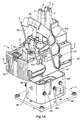
- reference numeral 1 denotes, as a whole, a high-voltage electrical connector which can be used, for example, for connection to the battery powering an electric traction motor for an electric traction motor vehicle. It should be noted that although the invention is illustrated in this instance with reference to such a specific application, it may nonetheless be used with any other type of connector which has a sliding element for controlling closure of the connector.
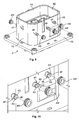
- the connector 1 comprises a first connector element 2, which can be seen separately in Figs 11A and 11B , having a box-like body which is made of plastics materials and downwardly open with an upper wall 2U, a front wall 2F, a rear wall 2R and two side walls 2S.
- the body of the first connector element 2 further includes a central core 2C defining five prismatic tubular bodies 2T projecting from the upper wall 2U and extending as far as the base of the body of the connector element 2 so as to define a peripheral receptacle 2L between the central core 2C and the walls 2F, 2R, 2S of the body of the connector element 2 (see Fig. 11B ).
- the prismatic tubular elements 2T receive the same number of contacts (not visible in the drawings) of any type known per se with five conductors 3 arranged at the ends thereof.
- the contacts are not shown in the drawings provided, both because (as mentioned above) they may be of any known type and also because they themselves are not the subject of the present invention.
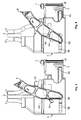
- the connector 1 further comprises a second connector element 4 which can be seen separately in Fig. 9 .
- the connector 4 has a body made of plastics material incorporating a base plate 4B from which a box-like body projects upwardly and includes two spaced, parallel side walls 4S and two spaced, parallel end walls 4E.
- Prismatic tubular elements 4T which receive the respective electrical contacts of any known type, adapted for coupling to the electrical contacts carried by the first connector element 2 extend upwardly within the space defined by the walls 4S, 4E.
- the contacts of the element 4 are also not shown in the drawings, both because (as mentioned above) they may be of any known type and also because they themselves are not the subject of the present invention.
- each pin 4P has a diametrical slot 4F which defines two resiliently deformable half-pins, of which the head is provided with projections 4G which axially retain the respective cog 4W once is it has been clicked onto the pin 4P.
- each cog 4W has a toothed rolling surface.
- the substantially tubular body defined by the walls 4S, 4E of the second connector element 4 is slidingly received in the peripheral receptacle 2L of the first connector element 2.
- the inner faces of the two side walls 2S of the first connector element slidingly guide the side walls 5S of a substantially U-shaped sliding element 5 with a front wall 5F (see Fig. 7 ).
- the sliding element 5 is slidingly mounted between the two side walls 2S of the first connector element 2 between an extended position (for example shown in Fig 1 and in Fig. 3 ) and a retracted position (shown in Fig. 2 and in Fig. 6 ).
- each of the two side walls 5S of the sliding element 5 is formed with three grooves 5F, each of which receives a respective cog 4W carried by the second connector element 4.
- Each groove 5F is downwardly delimited by a generally planar, inclined surface which defines a track 5T for the respective cog 4W.
- the generally planar, inclined surface of each track 5T is toothed and cooperates with the toothed rolling surface of the respective cog 4W in such a way that when the sliding element is brought out of the extended position shown in Fig. 1 , in which the front wall 5F is spaced from the front wall 2F of the first connector element 2, and into the retracted position shown in Fig.
- the tracks 5T act as cam tracks which force the second connector element to be raised until arranged in the state coupled to the first connector element, in which the respective electrical contacts are coupled, whilst the cogs 4W carried by the second connector element 4 are forced to rotate along the tracks 5T in the sliding member 5.
- Each of the grooves 5C formed in the inner face of the walls 5S of the sliding element 5 is wider than the diameter of the respective cog 4W so as to ensure that each cog 4W rolls on the respective track 5T without contacting the opposite side of the respective groove 5C.
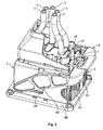
- the lever 6 has a substantially U-shaped plastics material body with a central crossbar 6C which connects two side arms 6S. In the vicinity of their free ends, the side arms 6S have two projecting pins 6A, 6B facing their inner surfaces which engage with respective slots 2A, 2B penetrating the two side walls 2S of the body of the first connector element 2 (see in particular Figs 3-6 ).
- the slot 2A is curved, whereas the slot 2B is straight and orientated in the direction of movement of the sliding element 5.
- the pins 6B of the lever 6 project inside the respective walls 2S and engage two respective seats 5P formed in the outer faces of the side walls 5S of the sliding element 5 (see Fig. 7 ).
- the movement of the lever 6 from the position shown in Fig. 3 to the position shown in Fig. 6 , through the positions shown in Figs 4 and 5 causes the progressive movement of the sliding element 2 from its fully extended position to its fully retracted position.
- the prearrangement of a lever of the type illustrated is not essential and is generally only preferred when the force for closing the connector is substantially greater than usual levels. Normally, the prearrangement of the lever is not necessary owing to the reduction in the closure force obtained by the use of the rolling elements 4W.
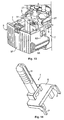
- the front wall 5F of the sliding element 5 is provided on its upper edge with a button 7 for securing the connector in the closed state.
- the button 7 (see Fig. 13 ) is received in a seat formed in the upper edge of the front wall 5F and is slidingly mounted vertically in said wall between a deactivated, raised position and an activated, lowered position in which it is received in a respective seat 7F formed in the front wall 2F of the first connector element 2.
- teeth 5D carrying resilient arms are formed in the side walls 5S of the sliding element and, once the sliding element 5 has been brought into the retracted state, prevent it from returning to the fully extended position by engagement with stop surfaces (not shown in the drawings) formed in the side walls 2S of the first connector element 2. If it is desired to move the sliding element 5 into its fully extended position, it is necessary to use a tool T (shown in Fig. 14 ) having a grip H which extends from a base plate B which can be positioned above the sliding element 5 when said sliding element is only partly extended, the teeth 5D contacting said stop surfaces.
Landscapes
- Details Of Connecting Devices For Male And Female Coupling (AREA)
- Cable Accessories (AREA)
Priority Applications (1)
| Application Number | Priority Date | Filing Date | Title |
|---|---|---|---|
| PL11707624T PL2543115T3 (pl) | 2010-03-04 | 2011-02-28 | Łącznik elektryczny |
Applications Claiming Priority (2)
| Application Number | Priority Date | Filing Date | Title |
|---|---|---|---|
| ITTO2010A000162A IT1398888B1 (it) | 2010-03-04 | 2010-03-04 | Connettore elettrico |
| PCT/EP2011/052884 WO2011107416A1 (en) | 2010-03-04 | 2011-02-28 | Electrical connector |
Publications (2)
| Publication Number | Publication Date |
|---|---|
| EP2543115A1 EP2543115A1 (en) | 2013-01-09 |
| EP2543115B1 true EP2543115B1 (en) | 2014-01-08 |
Family
ID=42712450
Family Applications (1)
| Application Number | Title | Priority Date | Filing Date |
|---|---|---|---|
| EP11707624.0A Active EP2543115B1 (en) | 2010-03-04 | 2011-02-28 | Electrical connector |
Country Status (8)
| Country | Link |
|---|---|
| US (1) | US8632349B2 (zh) |
| EP (1) | EP2543115B1 (zh) |
| JP (1) | JP5674826B2 (zh) |
| CN (1) | CN102782954B (zh) |
| BR (1) | BR112012021895A2 (zh) |
| IT (1) | IT1398888B1 (zh) |
| PL (1) | PL2543115T3 (zh) |
| WO (1) | WO2011107416A1 (zh) |
Families Citing this family (5)
| Publication number | Priority date | Publication date | Assignee | Title |
|---|---|---|---|---|
| US9160109B2 (en) * | 2013-12-13 | 2015-10-13 | Yazaki North America, Inc. | Lever actuated electrical center assembly |
| DE102014202296A1 (de) * | 2014-02-07 | 2015-08-13 | Robert Bosch Gmbh | Elektrisches Gerät und Verbindungsanordnung mit einem elektrischen Gerät |
| US9379486B2 (en) * | 2014-11-20 | 2016-06-28 | Delphi Technologies, Inc. | Ratcheting lever actuated connector assembly |
| IT202000022711A1 (it) * | 2020-09-25 | 2022-03-25 | Te Connectivity Italia Distribution Srl | Assieme di alloggiamento per un connettore elettrico |
| WO2024172024A1 (ja) * | 2023-02-13 | 2024-08-22 | 宏致電子股▲ふん▼有限公司 | ロック機構及びコネクターセット |
Family Cites Families (10)
| Publication number | Priority date | Publication date | Assignee | Title |
|---|---|---|---|---|
| US5110301A (en) * | 1989-12-22 | 1992-05-05 | Sumitomo Wiring System Ltd. | Multi-way connector requiring less inserting force |
| US4984383A (en) * | 1990-03-16 | 1991-01-15 | Amp Incorporated | Dual action operating mechanism for a plugboard system |
| JPH04160775A (ja) * | 1990-10-22 | 1992-06-04 | Yazaki Corp | 嵌合操作用カム部材付きコネクタ |
| US5876226A (en) * | 1994-10-14 | 1999-03-02 | The Whitaker Corporation | Connector with cam member |
| US5921791A (en) * | 1996-04-09 | 1999-07-13 | Harness System Technologies Research, Ltd. | Connector connecting structure |
| GB2339080A (en) * | 1998-06-29 | 2000-01-12 | Havant International Ltd | Mounting and testing of electrical devices such as disc drives |
| IT1303186B1 (it) * | 1998-11-27 | 2000-10-30 | Framatome Connectors Italia | Connettore elettrico. |
| ITTO20010290A1 (it) * | 2001-03-27 | 2002-09-27 | Framatome Connectors Italia | Connetore elettrico. |
| US6824405B2 (en) * | 2001-11-02 | 2004-11-30 | Virginia Panel Corporation | Modular interface device with improved torsion shaft |
| ITTO20050089A1 (it) * | 2005-02-16 | 2006-08-17 | Fci Italia S P A | Connettore elettrico |
-
2010
- 2010-03-04 IT ITTO2010A000162A patent/IT1398888B1/it active
-
2011
- 2011-02-28 PL PL11707624T patent/PL2543115T3/pl unknown
- 2011-02-28 EP EP11707624.0A patent/EP2543115B1/en active Active
- 2011-02-28 WO PCT/EP2011/052884 patent/WO2011107416A1/en active Application Filing
- 2011-02-28 JP JP2012555375A patent/JP5674826B2/ja not_active Expired - Fee Related
- 2011-02-28 CN CN201180012229.1A patent/CN102782954B/zh active Active
- 2011-02-28 BR BR112012021895A patent/BR112012021895A2/pt not_active Application Discontinuation
- 2011-02-28 US US13/581,780 patent/US8632349B2/en active Active
Also Published As
| Publication number | Publication date |
|---|---|
| PL2543115T3 (pl) | 2014-05-30 |
| WO2011107416A1 (en) | 2011-09-09 |
| US8632349B2 (en) | 2014-01-21 |
| CN102782954B (zh) | 2015-07-29 |
| JP2013521598A (ja) | 2013-06-10 |
| BR112012021895A2 (pt) | 2016-05-24 |
| JP5674826B2 (ja) | 2015-02-25 |
| EP2543115A1 (en) | 2013-01-09 |
| IT1398888B1 (it) | 2013-03-21 |
| ITTO20100162A1 (it) | 2011-09-05 |
| US20120329302A1 (en) | 2012-12-27 |
| CN102782954A (zh) | 2012-11-14 |
Similar Documents
| Publication | Publication Date | Title |
|---|---|---|
| EP2543115B1 (en) | Electrical connector | |
| CN107109870B (zh) | 门闩系统 | |
| US9564701B2 (en) | Plug connector | |
| KR101685927B1 (ko) | 수동형 시트쿠션 익스텐션 장치 및 이를 포함하는 차량용 시트 | |
| US8939424B2 (en) | Seat slide device | |
| US9873358B2 (en) | Locking device for baby car seat | |
| RU2700293C2 (ru) | Установочная система для сиденья транспортного средства (варианты) | |
| CN113039339B (zh) | 用于引导可运动地支承的门扇的引导系统 | |
| US8845345B2 (en) | Electrical plug-in device with closure device | |
| US20160010371A1 (en) | Closure Device for Connecting Two Parts | |
| US10439324B2 (en) | Lever-type connector | |
| US10396320B2 (en) | Battery retention assembly and method | |
| CN101991249B (zh) | 止滑式拉链头 | |
| KR101183122B1 (ko) | 사물함용 손잡이 | |
| JP5233008B2 (ja) | カッターナイフ | |
| JP4972017B2 (ja) | 蓋体の開閉機構 | |
| CN104661881B (zh) | 用于安全带的锁扣装置 | |
| CN219613223U (zh) | 安全带锁扣装置和车辆 | |
| CN217374788U (zh) | 折叠器及具有其的滑板车 | |
| CN118508136A (zh) | 一种车辆充电插座 | |
| CN214907513U (zh) | 钉匣及吻合器 | |
| CN215761043U (zh) | 口盖机构和具有其的车辆 | |
| CN211684854U (zh) | 制动开关锁止组件 | |
| JP6025506B2 (ja) | カミソリハンドル | |
| KR100412514B1 (ko) | 차량용 도어체커 |
Legal Events
| Date | Code | Title | Description |
|---|---|---|---|
| PUAI | Public reference made under article 153(3) epc to a published international application that has entered the european phase |
Free format text: ORIGINAL CODE: 0009012 |
|
| 17P | Request for examination filed |
Effective date: 20120903 |
|
| AK | Designated contracting states |
Kind code of ref document: A1 Designated state(s): AL AT BE BG CH CY CZ DE DK EE ES FI FR GB GR HR HU IE IS IT LI LT LU LV MC MK MT NL NO PL PT RO RS SE SI SK SM TR |
|
| DAX | Request for extension of the european patent (deleted) | ||
| GRAP | Despatch of communication of intention to grant a patent |
Free format text: ORIGINAL CODE: EPIDOSNIGR1 |
|
| INTG | Intention to grant announced |
Effective date: 20130801 |
|
| GRAS | Grant fee paid |
Free format text: ORIGINAL CODE: EPIDOSNIGR3 |
|
| GRAA | (expected) grant |
Free format text: ORIGINAL CODE: 0009210 |
|
| AK | Designated contracting states |
Kind code of ref document: B1 Designated state(s): AL AT BE BG CH CY CZ DE DK EE ES FI FR GB GR HR HU IE IS IT LI LT LU LV MC MK MT NL NO PL PT RO RS SE SI SK SM TR |
|
| REG | Reference to a national code |
Ref country code: GB Ref legal event code: FG4D |
|
| REG | Reference to a national code |
Ref country code: CH Ref legal event code: EP |
|
| REG | Reference to a national code |
Ref country code: IE Ref legal event code: FG4D |
|
| REG | Reference to a national code |
Ref country code: AT Ref legal event code: REF Ref document number: 649231 Country of ref document: AT Kind code of ref document: T Effective date: 20140215 |
|
| REG | Reference to a national code |
Ref country code: DE Ref legal event code: R096 Ref document number: 602011004606 Country of ref document: DE Effective date: 20140220 |
|
| REG | Reference to a national code |
Ref country code: SE Ref legal event code: TRGR |
|
| REG | Reference to a national code |
Ref country code: AT Ref legal event code: MK05 Ref document number: 649231 Country of ref document: AT Kind code of ref document: T Effective date: 20140108 |
|
| REG | Reference to a national code |
Ref country code: NL Ref legal event code: VDEP Effective date: 20140108 |
|
| REG | Reference to a national code |
Ref country code: PL Ref legal event code: T3 |
|
| REG | Reference to a national code |
Ref country code: LT Ref legal event code: MG4D |
|
| PG25 | Lapsed in a contracting state [announced via postgrant information from national office to epo] |
Ref country code: IS Free format text: LAPSE BECAUSE OF FAILURE TO SUBMIT A TRANSLATION OF THE DESCRIPTION OR TO PAY THE FEE WITHIN THE PRESCRIBED TIME-LIMIT Effective date: 20140508 Ref country code: LT Free format text: LAPSE BECAUSE OF FAILURE TO SUBMIT A TRANSLATION OF THE DESCRIPTION OR TO PAY THE FEE WITHIN THE PRESCRIBED TIME-LIMIT Effective date: 20140108 Ref country code: NO Free format text: LAPSE BECAUSE OF FAILURE TO SUBMIT A TRANSLATION OF THE DESCRIPTION OR TO PAY THE FEE WITHIN THE PRESCRIBED TIME-LIMIT Effective date: 20140408 |
|
| PG25 | Lapsed in a contracting state [announced via postgrant information from national office to epo] |
Ref country code: AT Free format text: LAPSE BECAUSE OF FAILURE TO SUBMIT A TRANSLATION OF THE DESCRIPTION OR TO PAY THE FEE WITHIN THE PRESCRIBED TIME-LIMIT Effective date: 20140108 Ref country code: NL Free format text: LAPSE BECAUSE OF FAILURE TO SUBMIT A TRANSLATION OF THE DESCRIPTION OR TO PAY THE FEE WITHIN THE PRESCRIBED TIME-LIMIT Effective date: 20140108 Ref country code: ES Free format text: LAPSE BECAUSE OF FAILURE TO SUBMIT A TRANSLATION OF THE DESCRIPTION OR TO PAY THE FEE WITHIN THE PRESCRIBED TIME-LIMIT Effective date: 20140108 Ref country code: CY Free format text: LAPSE BECAUSE OF FAILURE TO SUBMIT A TRANSLATION OF THE DESCRIPTION OR TO PAY THE FEE WITHIN THE PRESCRIBED TIME-LIMIT Effective date: 20140108 Ref country code: FI Free format text: LAPSE BECAUSE OF FAILURE TO SUBMIT A TRANSLATION OF THE DESCRIPTION OR TO PAY THE FEE WITHIN THE PRESCRIBED TIME-LIMIT Effective date: 20140108 Ref country code: PT Free format text: LAPSE BECAUSE OF FAILURE TO SUBMIT A TRANSLATION OF THE DESCRIPTION OR TO PAY THE FEE WITHIN THE PRESCRIBED TIME-LIMIT Effective date: 20140508 |
|
| PG25 | Lapsed in a contracting state [announced via postgrant information from national office to epo] |
Ref country code: HR Free format text: LAPSE BECAUSE OF FAILURE TO SUBMIT A TRANSLATION OF THE DESCRIPTION OR TO PAY THE FEE WITHIN THE PRESCRIBED TIME-LIMIT Effective date: 20140108 Ref country code: BE Free format text: LAPSE BECAUSE OF FAILURE TO SUBMIT A TRANSLATION OF THE DESCRIPTION OR TO PAY THE FEE WITHIN THE PRESCRIBED TIME-LIMIT Effective date: 20140108 Ref country code: LV Free format text: LAPSE BECAUSE OF FAILURE TO SUBMIT A TRANSLATION OF THE DESCRIPTION OR TO PAY THE FEE WITHIN THE PRESCRIBED TIME-LIMIT Effective date: 20140108 Ref country code: RS Free format text: LAPSE BECAUSE OF FAILURE TO SUBMIT A TRANSLATION OF THE DESCRIPTION OR TO PAY THE FEE WITHIN THE PRESCRIBED TIME-LIMIT Effective date: 20140108 |
|
| REG | Reference to a national code |
Ref country code: CH Ref legal event code: PL |
|
| REG | Reference to a national code |
Ref country code: DE Ref legal event code: R097 Ref document number: 602011004606 Country of ref document: DE |
|
| PG25 | Lapsed in a contracting state [announced via postgrant information from national office to epo] |
Ref country code: RO Free format text: LAPSE BECAUSE OF FAILURE TO SUBMIT A TRANSLATION OF THE DESCRIPTION OR TO PAY THE FEE WITHIN THE PRESCRIBED TIME-LIMIT Effective date: 20140108 Ref country code: EE Free format text: LAPSE BECAUSE OF FAILURE TO SUBMIT A TRANSLATION OF THE DESCRIPTION OR TO PAY THE FEE WITHIN THE PRESCRIBED TIME-LIMIT Effective date: 20140108 Ref country code: DK Free format text: LAPSE BECAUSE OF FAILURE TO SUBMIT A TRANSLATION OF THE DESCRIPTION OR TO PAY THE FEE WITHIN THE PRESCRIBED TIME-LIMIT Effective date: 20140108 Ref country code: CH Free format text: LAPSE BECAUSE OF NON-PAYMENT OF DUE FEES Effective date: 20140228 Ref country code: MC Free format text: LAPSE BECAUSE OF FAILURE TO SUBMIT A TRANSLATION OF THE DESCRIPTION OR TO PAY THE FEE WITHIN THE PRESCRIBED TIME-LIMIT Effective date: 20140108 Ref country code: LI Free format text: LAPSE BECAUSE OF NON-PAYMENT OF DUE FEES Effective date: 20140228 |
|
| PLBE | No opposition filed within time limit |
Free format text: ORIGINAL CODE: 0009261 |
|
| STAA | Information on the status of an ep patent application or granted ep patent |
Free format text: STATUS: NO OPPOSITION FILED WITHIN TIME LIMIT |
|
| PG25 | Lapsed in a contracting state [announced via postgrant information from national office to epo] |
Ref country code: SK Free format text: LAPSE BECAUSE OF FAILURE TO SUBMIT A TRANSLATION OF THE DESCRIPTION OR TO PAY THE FEE WITHIN THE PRESCRIBED TIME-LIMIT Effective date: 20140108 |
|
| REG | Reference to a national code |
Ref country code: IE Ref legal event code: MM4A |
|
| 26N | No opposition filed |
Effective date: 20141009 |
|
| REG | Reference to a national code |
Ref country code: DE Ref legal event code: R097 Ref document number: 602011004606 Country of ref document: DE Effective date: 20141009 |
|
| PG25 | Lapsed in a contracting state [announced via postgrant information from national office to epo] |
Ref country code: IE Free format text: LAPSE BECAUSE OF NON-PAYMENT OF DUE FEES Effective date: 20140228 |
|
| REG | Reference to a national code |
Ref country code: HU Ref legal event code: AG4A Ref document number: E022022 Country of ref document: HU |
|
| PG25 | Lapsed in a contracting state [announced via postgrant information from national office to epo] |
Ref country code: SI Free format text: LAPSE BECAUSE OF FAILURE TO SUBMIT A TRANSLATION OF THE DESCRIPTION OR TO PAY THE FEE WITHIN THE PRESCRIBED TIME-LIMIT Effective date: 20140108 |
|
| REG | Reference to a national code |
Ref country code: FR Ref legal event code: PLFP Year of fee payment: 6 |
|
| PG25 | Lapsed in a contracting state [announced via postgrant information from national office to epo] |
Ref country code: MT Free format text: LAPSE BECAUSE OF FAILURE TO SUBMIT A TRANSLATION OF THE DESCRIPTION OR TO PAY THE FEE WITHIN THE PRESCRIBED TIME-LIMIT Effective date: 20140108 |
|
| PG25 | Lapsed in a contracting state [announced via postgrant information from national office to epo] |
Ref country code: SM Free format text: LAPSE BECAUSE OF FAILURE TO SUBMIT A TRANSLATION OF THE DESCRIPTION OR TO PAY THE FEE WITHIN THE PRESCRIBED TIME-LIMIT Effective date: 20140108 |
|
| PG25 | Lapsed in a contracting state [announced via postgrant information from national office to epo] |
Ref country code: BG Free format text: LAPSE BECAUSE OF FAILURE TO SUBMIT A TRANSLATION OF THE DESCRIPTION OR TO PAY THE FEE WITHIN THE PRESCRIBED TIME-LIMIT Effective date: 20140108 Ref country code: GR Free format text: LAPSE BECAUSE OF FAILURE TO SUBMIT A TRANSLATION OF THE DESCRIPTION OR TO PAY THE FEE WITHIN THE PRESCRIBED TIME-LIMIT Effective date: 20140409 |
|
| PG25 | Lapsed in a contracting state [announced via postgrant information from national office to epo] |
Ref country code: TR Free format text: LAPSE BECAUSE OF FAILURE TO SUBMIT A TRANSLATION OF THE DESCRIPTION OR TO PAY THE FEE WITHIN THE PRESCRIBED TIME-LIMIT Effective date: 20140108 Ref country code: LU Free format text: LAPSE BECAUSE OF NON-PAYMENT OF DUE FEES Effective date: 20140228 |
|
| REG | Reference to a national code |
Ref country code: FR Ref legal event code: PLFP Year of fee payment: 7 |
|
| REG | Reference to a national code |
Ref country code: FR Ref legal event code: PLFP Year of fee payment: 8 |
|
| PGFP | Annual fee paid to national office [announced via postgrant information from national office to epo] |
Ref country code: GB Payment date: 20180228 Year of fee payment: 8 |
|
| PG25 | Lapsed in a contracting state [announced via postgrant information from national office to epo] |
Ref country code: MK Free format text: LAPSE BECAUSE OF FAILURE TO SUBMIT A TRANSLATION OF THE DESCRIPTION OR TO PAY THE FEE WITHIN THE PRESCRIBED TIME-LIMIT Effective date: 20140108 |
|
| PG25 | Lapsed in a contracting state [announced via postgrant information from national office to epo] |
Ref country code: AL Free format text: LAPSE BECAUSE OF FAILURE TO SUBMIT A TRANSLATION OF THE DESCRIPTION OR TO PAY THE FEE WITHIN THE PRESCRIBED TIME-LIMIT Effective date: 20140108 |
|
| PGFP | Annual fee paid to national office [announced via postgrant information from national office to epo] |
Ref country code: PL Payment date: 20181217 Year of fee payment: 9 |
|
| PGFP | Annual fee paid to national office [announced via postgrant information from national office to epo] |
Ref country code: FR Payment date: 20190322 Year of fee payment: 18 |
|
| PGFP | Annual fee paid to national office [announced via postgrant information from national office to epo] |
Ref country code: SE Payment date: 20190212 Year of fee payment: 9 Ref country code: HU Payment date: 20190117 Year of fee payment: 9 |
|
| GBPC | Gb: european patent ceased through non-payment of renewal fee |
Effective date: 20190228 |
|
| PG25 | Lapsed in a contracting state [announced via postgrant information from national office to epo] |
Ref country code: GB Free format text: LAPSE BECAUSE OF NON-PAYMENT OF DUE FEES Effective date: 20190228 |
|
| PG25 | Lapsed in a contracting state [announced via postgrant information from national office to epo] |
Ref country code: CZ Free format text: LAPSE BECAUSE OF NON-PAYMENT OF DUE FEES Effective date: 20200229 |
|
| PG25 | Lapsed in a contracting state [announced via postgrant information from national office to epo] |
Ref country code: HU Free format text: LAPSE BECAUSE OF NON-PAYMENT OF DUE FEES Effective date: 20200301 |
|
| PG25 | Lapsed in a contracting state [announced via postgrant information from national office to epo] |
Ref country code: SE Free format text: LAPSE BECAUSE OF NON-PAYMENT OF DUE FEES Effective date: 20200229 |
|
| PG25 | Lapsed in a contracting state [announced via postgrant information from national office to epo] |
Ref country code: PL Free format text: LAPSE BECAUSE OF NON-PAYMENT OF DUE FEES Effective date: 20200228 |
|
| PGFP | Annual fee paid to national office [announced via postgrant information from national office to epo] |
Ref country code: DE Payment date: 20231229 Year of fee payment: 14 |
|
| PGFP | Annual fee paid to national office [announced via postgrant information from national office to epo] |
Ref country code: IT Payment date: 20240111 Year of fee payment: 14 |