EP2542954B1 - SYSTÈME ET PROCÉDÉ POUR LA GÉNÉRATION D'UN SIGNAL EN & xA;CORRÉLATION AVEC UNE OPÉRATION D'ENTRÉE MANUEL - Google Patents
SYSTÈME ET PROCÉDÉ POUR LA GÉNÉRATION D'UN SIGNAL EN & xA;CORRÉLATION AVEC UNE OPÉRATION D'ENTRÉE MANUEL Download PDFInfo
- Publication number
- EP2542954B1 EP2542954B1 EP11714482.4A EP11714482A EP2542954B1 EP 2542954 B1 EP2542954 B1 EP 2542954B1 EP 11714482 A EP11714482 A EP 11714482A EP 2542954 B1 EP2542954 B1 EP 2542954B1
- Authority
- EP
- European Patent Office
- Prior art keywords
- electrode
- detection
- electrodes
- gen
- receiving electrodes
- Prior art date
- Legal status (The legal status is an assumption and is not a legal conclusion. Google has not performed a legal analysis and makes no representation as to the accuracy of the status listed.)
- Active
Links
- 238000000034 method Methods 0.000 title claims description 19
- 230000002596 correlated effect Effects 0.000 title description 2
- 238000001514 detection method Methods 0.000 claims description 131
- 230000005484 gravity Effects 0.000 claims description 5
- 230000004044 response Effects 0.000 claims description 4
- 210000003811 finger Anatomy 0.000 description 31
- 230000006870 function Effects 0.000 description 8
- 230000008859 change Effects 0.000 description 7
- 230000000875 corresponding effect Effects 0.000 description 6
- 210000004247 hand Anatomy 0.000 description 5
- 230000008569 process Effects 0.000 description 5
- 125000006850 spacer group Chemical group 0.000 description 5
- 230000000694 effects Effects 0.000 description 4
- 230000008878 coupling Effects 0.000 description 3
- 238000010168 coupling process Methods 0.000 description 3
- 238000005859 coupling reaction Methods 0.000 description 3
- 238000009795 derivation Methods 0.000 description 3
- 238000013461 design Methods 0.000 description 3
- 230000004069 differentiation Effects 0.000 description 3
- 210000003414 extremity Anatomy 0.000 description 3
- 230000003993 interaction Effects 0.000 description 3
- 238000012545 processing Methods 0.000 description 3
- 230000002123 temporal effect Effects 0.000 description 3
- 230000009471 action Effects 0.000 description 2
- 238000011156 evaluation Methods 0.000 description 2
- 230000010354 integration Effects 0.000 description 2
- 238000013459 approach Methods 0.000 description 1
- 230000000712 assembly Effects 0.000 description 1
- 238000000429 assembly Methods 0.000 description 1
- 239000011248 coating agent Substances 0.000 description 1
- 238000000576 coating method Methods 0.000 description 1
- 238000004891 communication Methods 0.000 description 1
- 238000004883 computer application Methods 0.000 description 1
- 230000001419 dependent effect Effects 0.000 description 1
- 238000010586 diagram Methods 0.000 description 1
- 230000003292 diminished effect Effects 0.000 description 1
- 238000005516 engineering process Methods 0.000 description 1
- 230000005057 finger movement Effects 0.000 description 1
- 239000012212 insulator Substances 0.000 description 1
- 238000004519 manufacturing process Methods 0.000 description 1
- 239000000463 material Substances 0.000 description 1
- 238000005259 measurement Methods 0.000 description 1
- 230000004048 modification Effects 0.000 description 1
- 238000012986 modification Methods 0.000 description 1
- 230000001095 motoneuron effect Effects 0.000 description 1
- 230000000284 resting effect Effects 0.000 description 1
- 230000035945 sensitivity Effects 0.000 description 1
- 238000001228 spectrum Methods 0.000 description 1
- 210000003813 thumb Anatomy 0.000 description 1
- 238000011144 upstream manufacturing Methods 0.000 description 1
Images


Classifications
-
- G—PHYSICS
- G06—COMPUTING; CALCULATING OR COUNTING
- G06F—ELECTRIC DIGITAL DATA PROCESSING
- G06F3/00—Input arrangements for transferring data to be processed into a form capable of being handled by the computer; Output arrangements for transferring data from processing unit to output unit, e.g. interface arrangements
- G06F3/01—Input arrangements or combined input and output arrangements for interaction between user and computer
- G06F3/03—Arrangements for converting the position or the displacement of a member into a coded form
- G06F3/041—Digitisers, e.g. for touch screens or touch pads, characterised by the transducing means
- G06F3/044—Digitisers, e.g. for touch screens or touch pads, characterised by the transducing means by capacitive means
- G06F3/0445—Digitisers, e.g. for touch screens or touch pads, characterised by the transducing means by capacitive means using two or more layers of sensing electrodes, e.g. using two layers of electrodes separated by a dielectric layer
-
- G—PHYSICS
- G06—COMPUTING; CALCULATING OR COUNTING
- G06F—ELECTRIC DIGITAL DATA PROCESSING
- G06F3/00—Input arrangements for transferring data to be processed into a form capable of being handled by the computer; Output arrangements for transferring data from processing unit to output unit, e.g. interface arrangements
- G06F3/01—Input arrangements or combined input and output arrangements for interaction between user and computer
- G06F3/03—Arrangements for converting the position or the displacement of a member into a coded form
- G06F3/041—Digitisers, e.g. for touch screens or touch pads, characterised by the transducing means
- G06F3/0416—Control or interface arrangements specially adapted for digitisers
- G06F3/04164—Connections between sensors and controllers, e.g. routing lines between electrodes and connection pads
-
- G—PHYSICS
- G06—COMPUTING; CALCULATING OR COUNTING
- G06F—ELECTRIC DIGITAL DATA PROCESSING
- G06F3/00—Input arrangements for transferring data to be processed into a form capable of being handled by the computer; Output arrangements for transferring data from processing unit to output unit, e.g. interface arrangements
- G06F3/01—Input arrangements or combined input and output arrangements for interaction between user and computer
- G06F3/048—Interaction techniques based on graphical user interfaces [GUI]
- G06F3/0487—Interaction techniques based on graphical user interfaces [GUI] using specific features provided by the input device, e.g. functions controlled by the rotation of a mouse with dual sensing arrangements, or of the nature of the input device, e.g. tap gestures based on pressure sensed by a digitiser
- G06F3/0488—Interaction techniques based on graphical user interfaces [GUI] using specific features provided by the input device, e.g. functions controlled by the rotation of a mouse with dual sensing arrangements, or of the nature of the input device, e.g. tap gestures based on pressure sensed by a digitiser using a touch-screen or digitiser, e.g. input of commands through traced gestures
- G06F3/04883—Interaction techniques based on graphical user interfaces [GUI] using specific features provided by the input device, e.g. functions controlled by the rotation of a mouse with dual sensing arrangements, or of the nature of the input device, e.g. tap gestures based on pressure sensed by a digitiser using a touch-screen or digitiser, e.g. input of commands through traced gestures for inputting data by handwriting, e.g. gesture or text
-
- G—PHYSICS
- G06—COMPUTING; CALCULATING OR COUNTING
- G06F—ELECTRIC DIGITAL DATA PROCESSING
- G06F2203/00—Indexing scheme relating to G06F3/00 - G06F3/048
- G06F2203/041—Indexing scheme relating to G06F3/041 - G06F3/045
- G06F2203/04101—2.5D-digitiser, i.e. digitiser detecting the X/Y position of the input means, finger or stylus, also when it does not touch, but is proximate to the digitiser's interaction surface and also measures the distance of the input means within a short range in the Z direction, possibly with a separate measurement setup
Definitions
- the invention relates to a system, as well as a method for the generation of a signal correlated with a manual, especially gesture-like input operation executed by a user with his hands or fingers relative to a physical device, in which this signal is used for the control of an electronic device, especially of a computer system provided for using a user program.
- the aim of the invention is to create solutions, by which it is possible to generate input signals for signal processing operations, especially as control signals for user program interactions, which correlates particularly reliably and accurately with manual, especially gesture-like input operations executed by the user.
- US 2006/232567 A1 describes a system for providing capacitive multi-touch sensing.
- a system for generating input signals that correlates as such with manual input operations executed by the user, comprises:
- an input interface for manual input operations coordinated by the user, which allows to reliably distinguish between a free spatial movement of a finger and the physical contact of a structure, which accommodates the electrode arrangement.
- gestures as well as cursor control and selection processes, which are concluded or validated with a contact process, or contain one or several brief contact phases.
- the invention is suitable in a particular extent for the implementation of a "hidden interface", by which in the case of electronic equipments with usual design attributes can be offered an intuitively well controllable additional function.
- the invention is suitable especially for the use in the case of distinct plane shaped equipment components, especially displays, housings, user panels and especially also computer keyboards.
- the position detection is accomplished by means of a receiving electrode subgroup contained in the electrode group that comprises several subelectrodes spaced from each other.
- the individual electrodes are outlined preferably in such a way that the totality of the electrodes represents an area closed to a large extent.
- the electric connection of these electrodes to the circuit arrangement can be accomplished in such a way that the touch detection takes place by electric effects, which act primary on an electrode of the electrode group and in doing so it is detected by means of this electrode.
- This electrode can be configured in such a way, that it represents the largest electrode in size.
- This electrode can be configured in such a way, that it extents substantially on the same area as the position detection electrodes.
- This electrode provided for detecting the touch can be arranged also in front, or preferably behind the position detection electrodes.
- the detection of the touch can take place for example by the electrode determining the existence of a significant capacitive coupling of the electrode with the user.
- the electrode is covered with an insulator, so that no galvanic contact of the electrode occurs.
- this electrode serving for the touch detection can be galvanically contacted by the user.
- a touch status on the basis of a significant signal level it is also possible to determine the touch detection on the basis of dynamic features of the influences acting on the electrode. So for example a pronounced stagnancy of a voltage level applied on the electrode can be used, or a stagnancy of the capacitance of a capacitive system constituted under inclusion of that electrode can be used on a certain level as circumstantial evidence, that a status to be classified as contact may be given.
- the evaluation of a approximation status of the finger or the hand of an user to the system according to the invention, as touch status can also take place by several combined processing criteria, especially of the absolute signal level, the derivative with respect to the time response of the signal level, as well as where applicable also the results of triangulation.
- a triangulation result that is indicative for a contact can be effective for example a triangulation result, whose calculated individual distances to the position detection electrodes reveal that the detected object lies at least relatively near to the level defined by the position detection electrodes.
- the electrode group according to the invention can be configured to a great extent symmetrically relative to the shape of the individual electrodes as well as the management of each of them towards the other. Such concepts are especially suitable for one-hand input systems. It is also possible to configure the electrode group according to the invention in such a way, that it can be accomplished by means of a two-hand input. For such applications the electrode group can be configured in such a way that one zone of the same is intended for the particularly precise position detection for this purpose in an advantageous area of the corresponding device, and the remaining area is substantially intended for the touch detection.
- a particularly precise information about X-, Y-axis, and preferably about Z-axis can be also determined e.g. in the range of number pads, whereas in the key pad area assigned to the left hand those touch detection substantially is laid-out on the detection by the second hand of a contact of a physical component of the keyboard.
- the function of the electrodes can be determined on the base of the memory. It is also possible to dynamically adjust the function of the electrodes. So, for each approximation status for the position detection can be used an electrode group allowing a particularly reliable triangulation.
- the electrode group is configured in such a way, that it comprises a main electrode and those subelectrodes.
- the subelectrodes preferably are configured in such a way, that these each time have one smaller electrode surface as the main electrode.
- the subelectrodes can be designed especially with a small surface, so that the total area of the subelectrodes is smaller than the total area of the main electrode.
- the subelectrodes can be arranged in such a way, that these each time constitute an electrode pair that lies in front of the surface of the rectangle with respect to the centre. So it is possible to obtain by means of a left and a right subelectrode relatively precise data about the X-axis and to obtain by means of the lower and the upper electrode relatively precise data about the Y-axis. From the totality of this information it can then be determined the information about the Z-axis with a certain accordance and further approximation appraisals.
- the subelectrodes are also possible to place the subelectrodes, as relatively small, stout built electrodes, in the corresponding edge areas of the detection zone.
- the subelectrodes in an area embraced by the main electrode.
- the subelectrodes in this respect can be designed as an electrode group substantially close to the centre, or they can be arranged alternatively also in such a way, that their surface centre of gravity lie relatively close to the surface centre of gravity of an assigned quadrant or segment of the touch detection zone.
- the electrode arrangement is preferably configured in such a way, that the detection zone represents a substantially rectangular area.
- the electrode subgroup in this respect is configured preferably basically rotation symmetrical or even point symmetrical in the detection zone.
- the electrode subgroup is configured in such a way, that it comprises four subelectrodes, and that the position of the subelectrodes is fixed in such a way, that the surface centre of gravity of the subelectrodes represent the edges of a rectangle, a rhombus, or a square.
- this carrier electrode can be achieved a rearward shield.
- the carrier electrode can be connected to the circuit arrangement or another driver circuit in such a way, that this carrier electrode is operated as shield electrode, for the extensive shielding of the lower side of the electrode group.
- the carrier electrode can also be used even for the touch detection (compare Fig. 15 , 16 ).
- the invention By means of the invention it is possible to create an electronic device, that can be integrated into a device, in order to detect the position and the movement of limbs, especially the finger of the user in a spatial area in front of the device and to determine at the same time if the user touches the surface of the device.
- the invention creates a new communication channel between the user and the device operated by the same, which combines the freedom of the gesture control as well as the clearness of the operation based on the contact.
- the invention can be realized with an economic and extremely compact hardware.
- the circuit arrangement can be realized where applicable by a single ASIC (Application-specific integrated circuit).
- the circuit according to the invention can be implemented discretely also with commercially available components still in a relatively place saving way.
- the present invention creates a bridge between control concepts based on contacts and based on gestures without contact and allows integrating the technology into diffused computer applications (and similar).
- the invention paves the way and back up the acceptance for, or from controls based on gestures.
- the solution according to the invention comprises besides the system here indicated consisting of the particular electrode arrangement and the assigned circuit arrangement also a method for the provision of signals, which, within the scope of approximation processes, both includes extracted site information and touch information generated in case of contact of a equipment component.
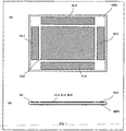
- Figure 1 shows the structure of the electrode group for a system according to the invention for generating input signals correlating as such with manual input operations executed by the user.
- the electrode group includes several plane shaped electrodes adjacent to each other EL1, EL2, EL3, EL4 and EL5. These electrodes EL1, EL2, EL3, EL4 and EL5 are connected to a circuit arrangement which is explained more in detail in the following in conjunction with the figure 2 .
- the electrode group defines in its totality a detection zone which both allows a spatial detection of limbs, especially a finger of the user, as well as a detection of an approximation status to evaluate a contact.
- the circuit arrangement connected to the electrodes EL1, EL2, EL3, EL4 and EL5 is configured in such a way, that via the electrode group EL1, EL2, EL3, EL4 and EL5 both a touch detection and a position detection are obtained, wherein the position detection is primarily executed by means of an electrode subgroup contained in the electrode group EL1, EL2, EL3, EL4 and EL5, that comprises several subelectrodes spaced from each other EL1, EL2, EL3, EL4.
- the system can be configured in such a way, that moving objects (fingers, hands%) which are situated relatively far over the electrodes, a presence detection or a slightly rougher position detection primarily occurs, that offers a limited spectrum of the interaction options. So for example after a longer fail of keyboard entries a screensaver mode can be disabled, when in a relatively wide spaced area the presence of the hands of the user is still recognized in front of a keyboard. In the case of detection of the presence of limbs, especially the hands of the user in a wider spaced area also certain user and gesture interpretation modes can be activated.
- a corresponding computer can be switched into a "full screen mode", in which no toolbars or vast control panels are visualised.
- this full screen mode few tendential rough motoric gestures can be recognized, e.g. a hint with the flat hand as "page-turning gesture” or "back page gesture” and a corresponding image reproduction can be initiated.
- an input mode via screen can, for example, be prevented, when a sufficient approximation to the keyboard takes place.
- the system according to the invention can also be used in a computer, such that, for example, by approximation with the finger of the right hand to a display screen a cursor can be navigated on this display screen.
- a cursor can be navigated on this display screen.
- certain functions can be coordinated like selections and scales. Concretely e.g. with the finger of the right hand an image can be selected from the image preview with numerous images arranged in lines and columns.
- the selected image can be amplified "zoomed” and diminished again. Also the drag and drop actions can be coordinated with this combi-system in an intuitive and particularly good controllable way.
- the electrode group EL1, EL2, EL3, EL4 and EL5 comprise a main electrode GEN and those subelectrodes EL1, EL2, EL3, EL4, EL5.
- the subelectrodes EL1, EL2, EL3, EL4, EL5 have each time one smaller electrode surface as the main electrode GEN.
- the subelectrodes EL1, EL2, EL3, EL4 especially can be configured in such a way, that their total area is smaller than the effective total area of the main electrode GEN.
- the subelectrodes EL1, EL2, EL3, EL4 are arranged as can be seen in the edge zone of the detection zone.
- the subelectrodes EL1, EL2, EL3, EL4 extend as small rectangular strips along the edge of the detection zone.
- a generator electrode GEN stressed by the voltage with the generator signal.
- the latter comprises, as already mentioned, four strip shaped subelectrodes serving as position detection electrodes EL1, EL2, EL3, EL4 and a centrally arranged touch detection electrode EL5. (the number of the electrodes can be smaller or greater depending also on the application).
- the generator electrode GEN in this exemplary embodiment is placed below all measuring electrodes.
- the electrodes are arranged in a structure of two layers with an insulating layer between.
- the electrode arrangement in-this respect can be realized e.g. on a two layer printed circuit (see lower representation of Fig.).
- a distinguishing feature of the lower arrangement, which allows the touch detection, is to manufacture the large electrode EL5 such that it fills the surface not occupied by the electrodes EL1 to EL4.
- the touch-sensitive area therewith extends over the electrodes EL1 to EL5.
- the electrodes are connected to the inputs of the gesture IC / of the gesture circuit.
- CH1 to CH5 are although the (same) channels of the circuit.
- the measuring circuit presents highly resistive inputs. Therefore the electrode EL5 does not interfere with the function of the position detection electrodes EL1 to EL4.
- the electrode EL5 has a strong capacitive coupling to the generator electrode GEN and a similar electric potential. For this reason the range of the measuring device is not affected by the introduction of the electrode EL5, this applies also for the electrode arrangements according to the figures 7 and 8 . In this case the range even is increased by the effect of the electrode EL5.
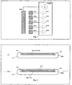
- the two exemplary embodiments shown in the figure 3 show two of the possibilities for the disposition of the touch detection electrode EL5.
- the embodiment according to the figure 3a corresponds to the embodiment according to figure lb.
- the touch detection electrode EL5 extends in a level, that is displaced to the electrode level defined by the electrodes EL1, EL2, EL3 and EL4.
- the touch detection electrode EL5 can be situated directly below the structure of a housing or a top layer of a display.
- the touch detection electrode EL5 can be executed as an extensive transparent electrode. This transparent effect can be obtained in that the touch detection electrode EL5 being either executed sufficiently thin, for example as a vacuum metallizing or chemically deposited metallic layer or e.g. an ITO layer, as a layer of a conductive plastic material, or as a fine-webbed lattice structure.
- the touch detection electrode EL5 being either executed sufficiently thin, for example as a vacuum metallizing or chemically deposited metallic layer or e.g. an ITO layer, as a layer of a conductive plastic material, or as a fine-webbed lattice structure.
- the partial frame (a) shows a variant, in which all the electrodes are situated inside a housing.
- the electrode EL5 is placed on the surface of the housing. In this case the signal change in the case of a contact is the greatest and thus significantly dominant.
- FIG 4 the indexes of refraction of the input signals scanned by the electrodes by means of the system are illustrated according to the invention.
- the configuration of the electrode arrangement based on this measurement corresponds to the disposition according to the figure 3a .
- the shown signal is the signal scanned only by one electrode.
- the individual partial frames represent:
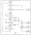
- FIG 5 a possible algorithm of the differentiation is shown. This processes, as input parameter, the amplitude of the signal S, the derivative with respect to time of the signal dS/dt and the temporal difference A between the determined events.
- the signals of the electronic gestures have a strong non-linearity (as the square and cubic dependence from the distance): the closer a finger, or a other action relevant object lies in a electrode, the greater is the absolute change of the signal in an equal distance change. This attitude increases the security of the determination of the contact, because also a slower approximation to the housing of the device means a great value of the signal derivation.
- FIG 6 another configuration of electrodes is shown, in which the position detection electrodes EL1, EL2, EL3, EL4 though are arranged similar to the exemplary embodiment according to figure la in the external edge zone of the touch detection zone, but not as thin strips, but rather as compact, stocky edge electrodes are executed. These special edge electrodes have smaller sizes and lies in the edges of the detection area.
- the touch detection electrode EL5 fills the area between the electrodes EL1, EL2, EL3, EL4.
- Figure 7 shows a variant in which the position detection electrodes EL1, EL2, EL3, EL4 lie in the detection area, and are surrounded by the touch detection electrode EL5.
- the position detection electrodes EL1, EL2, EL3, EL4 are configured as coin size circular disks. Between these position detection electrodes EL1, EL2, EL3, EL4 and the touch detection electrode EL5 are shaped relatively wide annular free zones.
- Figure 8 shows a variant in which the position detection electrodes EL1, EL2, EL3, EL4 are executed extremely compact and placed in the middle of the detection area.
- the touch detection electrode EL5 defines the detection area for the contact.
- the detection range for determining the position is greater.
- the geometries of the electrodes described above are exemplary types. Also other geometries are possible, that can differ especially in the shape and its relative positions of the electrodes. It is also possible using instead of the EL5 the generator electrode, as it is described below.
- the number of the electrodes can be varied according to the application.
- the number of the position detection electrodes can vary from 1 (mere approximation detection) to e.g. 8 or in special cases also more.
- the number of the touch detection electrodes can vary. So e.g. the detection area can be divided in three lower zones with three touch detection electrodes.
- connection of the electrodes to the gesture electronics denominated in the following as evaluation circuit can take place by conducting paths, preferably shielded conducting paths, here not represented more in detail. Such connections can be executed in a additional layer of printed circuits or in the case of the two-layer printed circuit exemplary illustrated in Fig. 9 (for the electrode configuration of Fig. 8 ).
- the touch detection electrode and the generator of this electrode can be provided with cuts, a particularly high signal quality being obtained, if these cuts as well as the conducting paths of the connection of the electrodes preferably are a relative small portion of the electrode surface.
- FIG 9 a variant is illustrated, in which besides the electrodes also the conducting paths of the connection and whose possible contacting K can be recognized. It is possible to design this structure of the electrode as a widely transparent structure that can be arranged at least nearly invisible directly on a display.
- the touch detection electrode for this purpose can be executed as a extremely thin metallic layer, or as a ITO layer, or as a web / grid.
- the touch detection electrode is connected to one of the inputs of the gesture electronics. This input has not to be specially designed for this purpose. According to the invention it is also possible to detect the capacitive load of the generator electrode by means of a corresponding modification of the electronics and to derive on this basis an indicative signal for a touch status.
- the generator electrode GEN acts as a touch detection electrode (see also the Fig. 1 ).
- the touch detection is effected by measuring the capacitive load C of the generator electrode GEN.
- This load C e.g. can take place by measuring the voltage drop at a connection impedance Z, that is connected between the generator G and the generator electrode GEN (schematically illustrated as signal S in the Fig. 11 ).
- This method of the detection of the touch thereby can be advantageous, as this can be implemented in certain applications with a minor expenditure in electrodes.
- FIG. 13 An electrode configuration particularly advantageous for the structure around a display is shown in Fig. 13 .
- the generator electrode GEN is executed as frame below the position detection electrodes EL1, EL2, EL3, EL4 and it must not be transparent, in order to not cover the subjacent display D.
- the shield of EL1 to EL4 of the display and the touch detection is carried out by the transparent electrode SE that is situated in a layer between the generator electrode GEN and the display D.
- the shielding electrode SE When the generator electrode GEN is sensitive for the change of capacitance, the shielding electrode SE must not be connected galvanically, since its capacitive coupling CK to the generator electrode GEN is sufficient for the function ( Fig. 14 ).
- the system according to the invention with a carrier electrode, that extends on one lower side of the electrode relative to the detection zone below the electrode group.
- a rear shielding can be achieved.
- the carrier electrode can be connected to the circuit arrangement or another driver circuit, in such a way that this carrier electrode is operated as shielding electrode, for the extensive shielding of the lower side of the electrode group.
- the carrier electrode can be also used even for the touch detection.
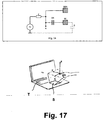
- a portable computer that comprises a keyboard T as well as an input system S according to the invention.
- This input system is configured in such a way that it allows the generation of input signals, which correlate as such with manual input operations executed by the user.
- the input system comprises an electrode group integrated into the touch pad area near the keyboard comprising several plane electrodes adjacent to each other.
- the input system comprises moreover a circuit arrangement coupled to the electrodes of the electrode group.
- the electrode group and the circuit arrangement constitute a sensor circuit which both allow a detection of a status to evaluate as a physical contacting of the equipment component, and a position detection of the hand or a finger of a user in a area placed spatially upstream of the equipment component.
- a physical contacting occurs a two-dimensional resolution of the finger position. While the finger, as indicated, lies in an observation area situated on the input system takes place a spatial resolution of the finger top position.
- FIG 18 a variant of a system is shown according to the invention executed as a flat structure and can be coupled by means of electrical signals with a computer system R.
- a computer system R In this flat structure of the housing is situated an electrode arrangement, that both allows a spatial position resolution of the finger top position and a two dimensional position resolution in case of the physical contacting, or - depending on the configuration - from sufficiently narrow approximation.
- the position detection occurs on the basis of capacitive interaction effects, their dimension correlates in the end with the position of the hand of the user.
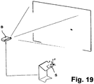
- FIG 19 is shown the use of the system according to the invention in connection with a projection apparatus B.
- a system S according to the invention that allows a detection of the spatial position of a finger of the speaker and a gesture detection and a cursor control based on this.
- the system S is configured in such a way, that it changes from the 3D-mode into a touch pad mode with 2D finger position detection in case of physical contacting.
- a system for generating input signals correlating as such with manual input operations executed by the user may comprise an electrode group integrated into a equipment component comprising several flat shaped electrodes adjacent to each other, and a circuit arrangement coupled with the electrodes of the electrode group, wherein the electrode group and the circuit arrangement constitute a sensor circuit which both allows a detection of a status to evaluate as physical contacting of the equipment component, and also a position detection of the hand or a finger of a user in a area which is spatially located in front of the equipment component.
- the position detection primary can be accomplished by means of an electrode subgroup contained in the electrode group comprising several subelectrodes spaced one from the others.
- the electrode group can be configured in such a way that it substantially covers in its totality the full surface area serving as touch detection zone surface.
- the electrode group may comprise a main electrode and those subelectrodes.
- the total area of the subelectrodes can be smaller than the total area of the main electrode or the subelectrodes each time have one smaller electrode surface as the main electrode, or that the subelectrodes can be arranged in the edge zone of the detection zone, and/or the subelectrodes can be strip-like electrode structures extend along the edge of the detection zone.
- the detection zone may comprise edge zones, and that the subelectrodes are arranged in these edge areas.
- the subelectrodes can be arranged in an area embraced by the main electrode, and/or the detection zone may represent a substantially rectangular area, and/or the electrode subgroup substantially may be configured rotation symmetrical in the detection zone.
- the electrode subgroup may comprise four subelectrodes and the position of the subelectrodes can be fixed so that the surface centres of gravity of the subelectrodes represent the edges of a rectangle, a rhombus, or a square.
- a carrier electrode can be provided that extends on one lower side of the electrode relative to the detection zone below the electrode group.
- this carrier electrode can be connected to the circuit arrangement, and this carrier electrode can be operated as shielding electrode for the extensive shielding of the lower part of the electrode group.
- at least one of the electrodes can be transparent, especially designed as an ITO layer electrode.
- a method for generating input signals correlating as such with manual input operations executed by the user by means of an electrode group integrated into a equipment component comprising several plane shaped electrodes adjacent to each other, takes place both a detection of a status to evaluate as a physical contacting of the equipment component, and a position detection in an area placed spatially in front of the equipment component, wherein the touch detection takes place according to a detection criterion, that is applied on the signals, or values derived thereof which are determined or generated within the scope of the position detection.
- the detection criterion can be a dynamic criterion concerning the occurrence of characteristics over the time response of the indicative signal contribution relative to the position of the Z-axis.
- this detection criterion may comprise an observation of a detected position of the Z-axis, and that a contact is detected, when a certain distance to the equipment component appears as to be below.
- a contact in the case of a contact a two-dimensional detection of the movement of a finger and a spatial detection of a finger or a hand of a user is made possible, wherein the function of a computer system connected to the display device can be coordinated by gesture-like inputs, which are executed in front of the display device.
- a computer monitor may comprise a display and a keyboard equipment, in which both in the display, and in the keyboard equipment is integrated a detection means allowing in a field-electrical way a spatial detection of a finger or a hand of a user, wherein the device function can be coordinated by gesture-like inputs that are executed in front of the display and in front of the keyboard equipment.
Claims (15)
- Système destiné à générer des signaux d'entrée en corrélation avec des opérations d'entrée manuelle exécutées par l'utilisateur, comportant :- un groupe d'électrodes comprenant une électrode génératrice (GEN) et une pluralité d'électrodes réceptrices associées (EL1-5) intégrées dans un composant d'équipement, dans lequel l'électrode génératrice (GEN) et la pluralité d'électrodes réceptrices (EL1-5) sont formées par des électrodes de forme plate et au moins certaines des électrodes réceptrices (EL1-4) sont agencées dans un plan et s'étendent le long de l'arête d'une zone de détection, et dans lequel l'électrode génératrice (GEN) est agencée dans un plan en dessous du plan des électrodes réceptrices (EL1-5) ; et- un agencement de circuit (GestIC) couplé avec les électrodes (GEN, EL1-5) du groupe d'électrodes ;- dans lequel le groupe d'électrodes et l'agencement de circuit (GestIC) constituent un circuit de capteur qui à la fois permet une détection d'un état à évaluer comme un contact physique du composant d'équipement, et également comme une détection de position de la main ou d'un doigt d'un utilisateur dans une zone qui est spatialement située en regard du composant d'équipement.
- Système selon la revendication 1, caractérisé en ce que la détection de position est accomplie au moyen d'un sous-groupe d'électrodes réceptrices (EL1-4) contenu dans le groupe d'électrodes comportant plusieurs électrodes réceptrices (EL1-4) espacées les unes des autres.
- Système selon la revendication 2, caractérisé en ce que le groupe d'électrodes est configuré de sorte que les électrodes réceptrices (EL1-5) couvrent sensiblement la zone de surface complète servant de surface de zone de détection tactile.
- Système selon la revendication 3, caractérisé en ce que l'électrode génératrice (GEN) couvre la zone de détection.
- Système selon au moins l'une des revendications 1 à 4, caractérisé en que la superficie totale des électrodes réceptrices (EL1-5) est inférieure à la superficie totale de l'électrode génératrice (GEN) ou en ce que les électrodes réceptrices (EL1-5) présentent chacune une surface d'électrode plus petite que celle de l'électrode génératrice (GEN).
- Système selon au moins l'une des revendications 1 à 5, caractérisé en ce que quatre électrodes réceptrices (EL1-4) sont agencées dans des zones le long de quatre arêtes de la zone de détection.
- Système selon au moins l'une des revendications 1 à 6, caractérisé en ce que la zone de détection représente une zone sensiblement rectangulaire, et/ou en ce que les électrodes réceptrices (EL1-5) sont sensiblement configurées comme étant symétriques en rotation dans la zone de détection.
- Système selon au moins l'une des revendications 1 à 7, caractérisé en ce que les électrodes réceptrices (EL1-5) incluent quatre électrodes réceptrices (EL1-4) dont la position est fixe de sorte que les centres de gravité de surface des électrodes réceptrices (EL1-4) représentent les arêtes d'un rectangle, d'un losange ou d'un carré.
- Système selon au moins l'une des revendications 1 à 8, caractérisé en ce qu'une électrode génératrice supplémentaire (GEN') est fournie laquelle est agencée dans le même plan que les électrodes réceptrices (EL1-4), et les électrodes réceptrices (EL1-4) sont agencées autour d'un périmètre de l'électrode génératrice supplémentaire (GEN').
- Système selon l'une quelconque des revendications 1 à 9, comprenant en outre une électrode de protection (SE), en particulier une électrode de protection transparente (SE), agencée entre l'électrode génératrice (GEN) et un affichage (D).
- Système selon au moins l'une des revendications 1 à 10, caractérisé en ce qu'au moins l'une des électrodes est transparente, et spécialement conçue comme une électrode de couche ITO.
- Procédé de génération de signaux d'entrée en corrélation avec des opérations d'entrée manuelle exécutées par un utilisateur, dans lequel un groupe d'électrodes est intégré dans un composant d'équipement comportant plusieurs électrodes réceptrices de forme plate (EL1-5) et une électrode génératrice (GEN), dans lequel l'électrode génératrice (GEN) et la pluralité d'électrodes réceptrices (EL1-5) sont formées par des électrodes de forme plate et au moins certaines des électrodes réceptrices (EL 1-4) sont agencées dans un plan et s'étendent le long de l'arête d'une zone de détection, et dans lequel l'électrode génératrice (GEN) est agencée dans un plan en dessous du plan des électrodes réceptrices (EL1-5), le procédé comprenant les étapes ci-dessous consistant à :mettre en oeuvre, au moyen de ladite électrode génératrice (GEN) et desdites électrodes réceptrices (EL1-5), à la fois une détection d'un état à évaluer comme un contact physique du composant d'équipement et également comme une détection de position dans une zone placée spatialement en regard du composant d'équipement, dans lequel la détection tactile a lieu selon un critère de détection qui est appliqué aux signaux, ou des valeurs dérivées connexes qui sont déterminées ou générées dans le cadre de la détection de position.
- Procédé selon la revendication 12, caractérisé en ce que le critère de détection est un critère dynamique basé sur l'occurrence de caractéristiques sur la réponse temporelle de la contribution de signal indicative relativement à la position sur l'axe des Z.
- Procédé selon la revendication 12 ou 13, caractérisé en ce que le critère de détection comporte une observation d'une position détectée sur l'axe des Z, et en ce qu'un contact est détecté lorsque la position détectée est inférieure à une certaine distance jusqu'au composant d'équipement.
- Dispositif d'affichage comprenant un système selon l'une quelconque des revendications 1 à 11, dans lequel, en cas de contact, une détection bidimensionnelle du mouvement d'un doigt et une détection spatiale d'un doigt ou d'une main d'un utilisateur sont déterminées, dans lequel la fonction d'un système informatique connecté au dispositif d'affichage peut être coordonnée par des entrées gestuelles qui sont exécutées en regard du dispositif d'affichage.
Applications Claiming Priority (2)
| Application Number | Priority Date | Filing Date | Title |
|---|---|---|---|
| DE102010007582 | 2010-02-10 | ||
| PCT/EP2011/000639 WO2011098281A2 (fr) | 2010-02-10 | 2011-02-10 | Système et procédé pour la génération d'un signal corrélé avec une opération d'entrée manuelle |
Publications (2)
| Publication Number | Publication Date |
|---|---|
| EP2542954A2 EP2542954A2 (fr) | 2013-01-09 |
| EP2542954B1 true EP2542954B1 (fr) | 2017-11-01 |
Family
ID=44063510
Family Applications (1)
| Application Number | Title | Priority Date | Filing Date |
|---|---|---|---|
| EP11714482.4A Active EP2542954B1 (fr) | 2010-02-10 | 2011-02-10 | SYSTÈME ET PROCÉDÉ POUR LA GÉNÉRATION D'UN SIGNAL EN & xA;CORRÉLATION AVEC UNE OPÉRATION D'ENTRÉE MANUEL |
Country Status (8)
| Country | Link |
|---|---|
| US (1) | US9189093B2 (fr) |
| EP (1) | EP2542954B1 (fr) |
| JP (1) | JP5882232B2 (fr) |
| KR (1) | KR101769889B1 (fr) |
| CN (1) | CN103189824B (fr) |
| DE (1) | DE102011010919B4 (fr) |
| ES (1) | ES2655729T3 (fr) |
| WO (1) | WO2011098281A2 (fr) |
Families Citing this family (25)
| Publication number | Priority date | Publication date | Assignee | Title |
|---|---|---|---|---|
| EP2542954B1 (fr) | 2010-02-10 | 2017-11-01 | Microchip Technology Germany GmbH | SYSTÈME ET PROCÉDÉ POUR LA GÉNÉRATION D'UN SIGNAL EN & xA;CORRÉLATION AVEC UNE OPÉRATION D'ENTRÉE MANUEL |
| WO2013038293A1 (fr) | 2011-09-15 | 2013-03-21 | Koninklijke Philips Electronics N.V. | Interface utilisateur à base de gestes avec rétroaction d'utilisateur |
| KR101925485B1 (ko) * | 2012-06-15 | 2019-02-27 | 삼성전자주식회사 | 근접 터치 감지 장치 및 방법 |
| US9829996B2 (en) * | 2012-06-25 | 2017-11-28 | Zspace, Inc. | Operations in a three dimensional display system |
| US9459296B2 (en) | 2012-10-19 | 2016-10-04 | Microchip Technology Germany Gmbh Ii & Co. Kg | Electrode design for electric field measurement system |
| US9423939B2 (en) | 2012-11-12 | 2016-08-23 | Microsoft Technology Licensing, Llc | Dynamic adjustment of user interface |
| US9285889B2 (en) * | 2012-12-10 | 2016-03-15 | Intel Corporation | Electrode arrangement for a keyboard proximity and tracking sensor |
| US10352976B2 (en) | 2013-03-15 | 2019-07-16 | Microchip Technology Incorporated | Matrix electrode design for three-dimensional e-filed sensor |
| JP2014191654A (ja) * | 2013-03-27 | 2014-10-06 | Sharp Corp | 入力装置および電子機器 |
| EP3044653A4 (fr) * | 2013-09-12 | 2017-06-07 | Intel Corporation | Détection de gestes côté dispositif informatique |
| JP6174435B2 (ja) | 2013-09-25 | 2017-08-02 | 富士通コンポーネント株式会社 | コンバイナ及び操作検出装置 |
| KR101572331B1 (ko) * | 2013-12-26 | 2015-11-30 | (주)멜파스 | 터치스크린패널을 이용하여 근접 센싱 기능을 제공하는 터치 센싱 시스템 및 방법 |
| KR20150101609A (ko) * | 2014-02-27 | 2015-09-04 | 삼성전자주식회사 | 전자장치의 터치패널과 입력 처리 방법 및 장치 |
| US9921739B2 (en) * | 2014-03-03 | 2018-03-20 | Microchip Technology Incorporated | System and method for gesture control |
| KR102251356B1 (ko) | 2014-06-20 | 2021-05-12 | 삼성전자주식회사 | 전기장을 이용하는 전자 장치 |
| EP2988479B1 (fr) * | 2014-08-19 | 2019-01-30 | Semtech Corporation | Capteur de proximité capacitif et dispositif mobile |
| US10303285B2 (en) * | 2015-04-22 | 2019-05-28 | Microchip Technology Incorporated | Sensor device for a display |
| US9946397B2 (en) * | 2015-06-15 | 2018-04-17 | Microchip Technology Incorporated | Sensor design for enhanced touch and gesture decoding |
| TWM515150U (zh) * | 2015-07-22 | 2016-01-01 | 聯陽半導體股份有限公司 | 觸控電極層 |
| US10444892B2 (en) * | 2015-10-07 | 2019-10-15 | Microchip Technology Incorporated | Capacitance measurement device with reduced noise |
| US10359929B2 (en) * | 2015-11-09 | 2019-07-23 | Analog Devices, Inc. | Slider and gesture recognition using capacitive sensing |
| KR102635976B1 (ko) * | 2016-12-30 | 2024-02-13 | 에스엘 주식회사 | 제스처 인식 장치 |
| DE102017215333A1 (de) * | 2017-09-01 | 2019-03-07 | Witte Automotive Gmbh | Kapazitive Sensoranordnung und Fahrzeugaußengriff |
| US10908745B2 (en) * | 2018-06-22 | 2021-02-02 | The Florida International University Board Of Trustees | Three dimensional touch conductive fabric |
| KR102519800B1 (ko) * | 2018-07-17 | 2023-04-10 | 삼성디스플레이 주식회사 | 전자 장치 |
Family Cites Families (36)
| Publication number | Priority date | Publication date | Assignee | Title |
|---|---|---|---|---|
| GB9406702D0 (en) | 1994-04-05 | 1994-05-25 | Binstead Ronald P | Multiple input proximity detector and touchpad system |
| US6204839B1 (en) | 1997-06-27 | 2001-03-20 | Compaq Computer Corporation | Capacitive sensing keyboard and pointing device |
| KR100595925B1 (ko) | 1998-01-26 | 2006-07-05 | 웨인 웨스터만 | 수동 입력 통합 방법 및 장치 |
| US6680677B1 (en) | 2000-10-06 | 2004-01-20 | Logitech Europe S.A. | Proximity detector to indicate function of a key |
| US7656393B2 (en) * | 2005-03-04 | 2010-02-02 | Apple Inc. | Electronic device having display and surrounding touch sensitive bezel for user interface and control |
| CN100412766C (zh) * | 2003-08-29 | 2008-08-20 | 诺基亚公司 | 在基于触摸的用户输入装置上用于识别双点用户输入的方法和装置 |
| WO2005055028A2 (fr) | 2003-12-05 | 2005-06-16 | Rupprecht & Partner | Unite d'entree alphanumerique |
| GB0412787D0 (en) | 2004-06-09 | 2004-07-14 | Koninkl Philips Electronics Nv | Input system |
| US7323886B2 (en) * | 2004-08-16 | 2008-01-29 | Ying Lau Lee | Linear capacitance measurement and touchless switch |
| US20060244733A1 (en) * | 2005-04-28 | 2006-11-02 | Geaghan Bernard O | Touch sensitive device and method using pre-touch information |
| DE102005038678A1 (de) * | 2005-08-16 | 2007-02-22 | Ident Technology Ag | Erfassungssystem, sowie diesem unterlegtes Erfassungsverfahren |
| JP4908516B2 (ja) | 2005-10-28 | 2012-04-04 | イデント テクノロジー アーゲー | 少なくとも1つの電極に関して、物体の存在、位置及び/又は接近を検出する方法及び回路 |
| US7395717B2 (en) * | 2006-02-10 | 2008-07-08 | Milliken & Company | Flexible capacitive sensor |
| DE102006034415A1 (de) * | 2006-07-25 | 2008-01-31 | Siemens Ag | Verfahren und Anordnung zum Bedienen von elektrischen Geräten |
| US7813774B2 (en) * | 2006-08-18 | 2010-10-12 | Microsoft Corporation | Contact, motion and position sensing circuitry providing data entry associated with keypad and touchpad |
| WO2008059795A1 (fr) * | 2006-11-15 | 2008-05-22 | Alps Electric Co., Ltd. | Appareil de détection de direction de fonctionnement |
| US8970501B2 (en) | 2007-01-03 | 2015-03-03 | Apple Inc. | Proximity and multi-touch sensor detection and demodulation |
| US7877707B2 (en) * | 2007-01-06 | 2011-01-25 | Apple Inc. | Detecting and interpreting real-world and security gestures on touch and hover sensitive devices |
| JP5183494B2 (ja) * | 2007-01-31 | 2013-04-17 | アルプス電気株式会社 | 静電容量式モーション検出装置及びそれを用いた入力装置 |
| DE102007016408A1 (de) * | 2007-03-26 | 2008-10-02 | Ident Technology Ag | Mobiles Kommunikationsgerät und Eingabeeinrichtung hierfür |
| JP2009098834A (ja) | 2007-10-16 | 2009-05-07 | Epson Imaging Devices Corp | 静電容量型入力装置、入力機能付き表示装置および電子機器 |
| DE102007054239B4 (de) | 2007-11-12 | 2021-11-18 | Volkswagen Ag | Multifunktionsanzeige- und Bediensystem sowie Verfahren zum Bedienen von Funktionen und/oder Fahrzeugsystemen eines Kraftfahrzeugs mit einer verbesserten Bedienbarkeit mindestens eines Fahrzeugsystems oder einer Fahrzeugfunktion |
| DE102008051757A1 (de) | 2007-11-12 | 2009-05-14 | Volkswagen Ag | Multimodale Benutzerschnittstelle eines Fahrerassistenzsystems zur Eingabe und Präsentation von Informationen |
| JP4794010B2 (ja) * | 2008-01-16 | 2011-10-12 | 三菱自動車工業株式会社 | タッチセンサ装置、制御方法、タッチパネル装置、及びプログラム |
| JP2009183592A (ja) | 2008-02-08 | 2009-08-20 | Ge Medical Systems Global Technology Co Llc | 操作情報入力装置および超音波撮像装置 |
| JP4816668B2 (ja) | 2008-03-28 | 2011-11-16 | ソニー株式会社 | タッチセンサ付き表示装置 |
| KR101495164B1 (ko) * | 2008-04-10 | 2015-02-24 | 엘지전자 주식회사 | 이동단말기 및 그 화면 처리 방법 |
| JP5481040B2 (ja) * | 2008-04-11 | 2014-04-23 | 株式会社ジャパンディスプレイ | 表示装置とその駆動方法 |
| EP2300899A4 (fr) * | 2008-05-14 | 2012-11-07 | 3M Innovative Properties Co | Système et procédé permettant d'évaluer des positions d'entrées tactiles multiples |
| TWI460622B (zh) | 2008-06-20 | 2014-11-11 | Elan Microelectronics | 可解譯多物件手勢之觸控板模組及其操作方法 |
| US9335868B2 (en) * | 2008-07-31 | 2016-05-10 | Apple Inc. | Capacitive sensor behind black mask |
| US8368657B2 (en) * | 2008-12-01 | 2013-02-05 | Freescale Semiconductor, Inc. | Touch sensor panel using regional and local electrodes to increase number of sense locations |
| US20100156838A1 (en) * | 2008-12-18 | 2010-06-24 | Han Sang-Youl | Capacitive input display device |
| TWI460639B (zh) * | 2009-02-23 | 2014-11-11 | Innolux Corp | 影像顯示系統 |
| US8232990B2 (en) * | 2010-01-05 | 2012-07-31 | Apple Inc. | Working with 3D objects |
| EP2542954B1 (fr) | 2010-02-10 | 2017-11-01 | Microchip Technology Germany GmbH | SYSTÈME ET PROCÉDÉ POUR LA GÉNÉRATION D'UN SIGNAL EN & xA;CORRÉLATION AVEC UNE OPÉRATION D'ENTRÉE MANUEL |
-
2011
- 2011-02-10 EP EP11714482.4A patent/EP2542954B1/fr active Active
- 2011-02-10 CN CN201180008910.9A patent/CN103189824B/zh active Active
- 2011-02-10 WO PCT/EP2011/000639 patent/WO2011098281A2/fr active Application Filing
- 2011-02-10 ES ES11714482.4T patent/ES2655729T3/es active Active
- 2011-02-10 DE DE102011010919.6A patent/DE102011010919B4/de active Active
- 2011-02-10 KR KR1020127023201A patent/KR101769889B1/ko not_active Application Discontinuation
- 2011-02-10 JP JP2012552312A patent/JP5882232B2/ja active Active
- 2011-02-10 US US13/577,539 patent/US9189093B2/en active Active
Non-Patent Citations (1)
| Title |
|---|
| None * |
Also Published As
| Publication number | Publication date |
|---|---|
| WO2011098281A3 (fr) | 2012-12-20 |
| KR20130001724A (ko) | 2013-01-04 |
| EP2542954A2 (fr) | 2013-01-09 |
| JP5882232B2 (ja) | 2016-03-09 |
| US20130176236A1 (en) | 2013-07-11 |
| WO2011098281A2 (fr) | 2011-08-18 |
| CN103189824A (zh) | 2013-07-03 |
| KR101769889B1 (ko) | 2017-08-21 |
| DE102011010919A1 (de) | 2011-08-11 |
| DE102011010919B4 (de) | 2018-05-09 |
| US9189093B2 (en) | 2015-11-17 |
| ES2655729T3 (es) | 2018-02-21 |
| CN103189824B (zh) | 2017-06-09 |
| JP2013519930A (ja) | 2013-05-30 |
Similar Documents
| Publication | Publication Date | Title |
|---|---|---|
| EP2542954B1 (fr) | SYSTÈME ET PROCÉDÉ POUR LA GÉNÉRATION D'UN SIGNAL EN & xA;CORRÉLATION AVEC UNE OPÉRATION D'ENTRÉE MANUEL | |
| EP2901254B1 (fr) | Pavé tactile sensible à la pression | |
| EP3049898B1 (fr) | Pavé tactile sensible à la pression | |
| US9104283B2 (en) | Capacitive detection device with arrangement of linking tracks, and method implementing such a device | |
| EP3114555B1 (fr) | Système et procédé de commande par gestes | |
| CN101689080B (zh) | 用于触摸传感器的装置以及相关装置和方法 | |
| US9459734B2 (en) | Input device with deflectable electrode | |
| JP3877484B2 (ja) | 入力装置 | |
| US20150185946A1 (en) | Touch surface having capacitive and resistive sensors | |
| KR20070116065A (ko) | 복수의 터치 감지 장치를 가지는 핸드 헬드 전자 장치 | |
| WO2015044517A1 (fr) | Agencement d'électrode de protection réglable pour un réseau de capteurs tactiles capacitifs | |
| JP3132106U (ja) | 複合式タッチセンサー | |
| KR101655196B1 (ko) | 자동 모드 전환 방법 | |
| US20080158187A1 (en) | Touch control input system for use in electronic apparatuses and signal generation method thereof |
Legal Events
| Date | Code | Title | Description |
|---|---|---|---|
| PUAI | Public reference made under article 153(3) epc to a published international application that has entered the european phase |
Free format text: ORIGINAL CODE: 0009012 |
|
| 17P | Request for examination filed |
Effective date: 20120907 |
|
| AK | Designated contracting states |
Kind code of ref document: A2 Designated state(s): AL AT BE BG CH CY CZ DE DK EE ES FI FR GB GR HR HU IE IS IT LI LT LU LV MC MK MT NL NO PL PT RO RS SE SI SK SM TR |
|
| R17D | Deferred search report published (corrected) |
Effective date: 20121220 |
|
| RAP1 | Party data changed (applicant data changed or rights of an application transferred) |
Owner name: MICROCHIP TECHNOLOGY GERMANY II GMBH & CO. KG |
|
| DAX | Request for extension of the european patent (deleted) | ||
| GRAP | Despatch of communication of intention to grant a patent |
Free format text: ORIGINAL CODE: EPIDOSNIGR1 |
|
| STAA | Information on the status of an ep patent application or granted ep patent |
Free format text: STATUS: GRANT OF PATENT IS INTENDED |
|
| INTG | Intention to grant announced |
Effective date: 20170413 |
|
| RIN1 | Information on inventor provided before grant (corrected) |
Inventor name: IVANOV, ARTEM |
|
| GRAS | Grant fee paid |
Free format text: ORIGINAL CODE: EPIDOSNIGR3 |
|
| GRAA | (expected) grant |
Free format text: ORIGINAL CODE: 0009210 |
|
| STAA | Information on the status of an ep patent application or granted ep patent |
Free format text: STATUS: THE PATENT HAS BEEN GRANTED |
|
| RAP1 | Party data changed (applicant data changed or rights of an application transferred) |
Owner name: MICROCHIP TECHNOLOGY GERMANY GMBH |
|
| AK | Designated contracting states |
Kind code of ref document: B1 Designated state(s): AL AT BE BG CH CY CZ DE DK EE ES FI FR GB GR HR HU IE IS IT LI LT LU LV MC MK MT NL NO PL PT RO RS SE SI SK SM TR |
|
| REG | Reference to a national code |
Ref country code: GB Ref legal event code: FG4D |
|
| REG | Reference to a national code |
Ref country code: CH Ref legal event code: EP Ref country code: AT Ref legal event code: REF Ref document number: 942656 Country of ref document: AT Kind code of ref document: T Effective date: 20171115 |
|
| REG | Reference to a national code |
Ref country code: IE Ref legal event code: FG4D |
|
| REG | Reference to a national code |
Ref country code: DE Ref legal event code: R096 Ref document number: 602011042875 Country of ref document: DE |
|
| REG | Reference to a national code |
Ref country code: FR Ref legal event code: PLFP Year of fee payment: 8 |
|
| REG | Reference to a national code |
Ref country code: NL Ref legal event code: FP |
|
| REG | Reference to a national code |
Ref country code: ES Ref legal event code: FG2A Ref document number: 2655729 Country of ref document: ES Kind code of ref document: T3 Effective date: 20180221 |
|
| REG | Reference to a national code |
Ref country code: LT Ref legal event code: MG4D |
|
| REG | Reference to a national code |
Ref country code: AT Ref legal event code: MK05 Ref document number: 942656 Country of ref document: AT Kind code of ref document: T Effective date: 20171101 |
|
| PG25 | Lapsed in a contracting state [announced via postgrant information from national office to epo] |
Ref country code: FI Free format text: LAPSE BECAUSE OF FAILURE TO SUBMIT A TRANSLATION OF THE DESCRIPTION OR TO PAY THE FEE WITHIN THE PRESCRIBED TIME-LIMIT Effective date: 20171101 Ref country code: SE Free format text: LAPSE BECAUSE OF FAILURE TO SUBMIT A TRANSLATION OF THE DESCRIPTION OR TO PAY THE FEE WITHIN THE PRESCRIBED TIME-LIMIT Effective date: 20171101 Ref country code: LT Free format text: LAPSE BECAUSE OF FAILURE TO SUBMIT A TRANSLATION OF THE DESCRIPTION OR TO PAY THE FEE WITHIN THE PRESCRIBED TIME-LIMIT Effective date: 20171101 Ref country code: NO Free format text: LAPSE BECAUSE OF FAILURE TO SUBMIT A TRANSLATION OF THE DESCRIPTION OR TO PAY THE FEE WITHIN THE PRESCRIBED TIME-LIMIT Effective date: 20180201 |
|
| PG25 | Lapsed in a contracting state [announced via postgrant information from national office to epo] |
Ref country code: HR Free format text: LAPSE BECAUSE OF FAILURE TO SUBMIT A TRANSLATION OF THE DESCRIPTION OR TO PAY THE FEE WITHIN THE PRESCRIBED TIME-LIMIT Effective date: 20171101 Ref country code: BG Free format text: LAPSE BECAUSE OF FAILURE TO SUBMIT A TRANSLATION OF THE DESCRIPTION OR TO PAY THE FEE WITHIN THE PRESCRIBED TIME-LIMIT Effective date: 20180201 Ref country code: AT Free format text: LAPSE BECAUSE OF FAILURE TO SUBMIT A TRANSLATION OF THE DESCRIPTION OR TO PAY THE FEE WITHIN THE PRESCRIBED TIME-LIMIT Effective date: 20171101 Ref country code: IS Free format text: LAPSE BECAUSE OF FAILURE TO SUBMIT A TRANSLATION OF THE DESCRIPTION OR TO PAY THE FEE WITHIN THE PRESCRIBED TIME-LIMIT Effective date: 20180301 Ref country code: LV Free format text: LAPSE BECAUSE OF FAILURE TO SUBMIT A TRANSLATION OF THE DESCRIPTION OR TO PAY THE FEE WITHIN THE PRESCRIBED TIME-LIMIT Effective date: 20171101 Ref country code: RS Free format text: LAPSE BECAUSE OF FAILURE TO SUBMIT A TRANSLATION OF THE DESCRIPTION OR TO PAY THE FEE WITHIN THE PRESCRIBED TIME-LIMIT Effective date: 20171101 Ref country code: GR Free format text: LAPSE BECAUSE OF FAILURE TO SUBMIT A TRANSLATION OF THE DESCRIPTION OR TO PAY THE FEE WITHIN THE PRESCRIBED TIME-LIMIT Effective date: 20180202 |
|
| PG25 | Lapsed in a contracting state [announced via postgrant information from national office to epo] |
Ref country code: CZ Free format text: LAPSE BECAUSE OF FAILURE TO SUBMIT A TRANSLATION OF THE DESCRIPTION OR TO PAY THE FEE WITHIN THE PRESCRIBED TIME-LIMIT Effective date: 20171101 Ref country code: CY Free format text: LAPSE BECAUSE OF FAILURE TO SUBMIT A TRANSLATION OF THE DESCRIPTION OR TO PAY THE FEE WITHIN THE PRESCRIBED TIME-LIMIT Effective date: 20171101 Ref country code: EE Free format text: LAPSE BECAUSE OF FAILURE TO SUBMIT A TRANSLATION OF THE DESCRIPTION OR TO PAY THE FEE WITHIN THE PRESCRIBED TIME-LIMIT Effective date: 20171101 Ref country code: DK Free format text: LAPSE BECAUSE OF FAILURE TO SUBMIT A TRANSLATION OF THE DESCRIPTION OR TO PAY THE FEE WITHIN THE PRESCRIBED TIME-LIMIT Effective date: 20171101 Ref country code: SK Free format text: LAPSE BECAUSE OF FAILURE TO SUBMIT A TRANSLATION OF THE DESCRIPTION OR TO PAY THE FEE WITHIN THE PRESCRIBED TIME-LIMIT Effective date: 20171101 |
|
| REG | Reference to a national code |
Ref country code: DE Ref legal event code: R097 Ref document number: 602011042875 Country of ref document: DE |
|
| PG25 | Lapsed in a contracting state [announced via postgrant information from national office to epo] |
Ref country code: RO Free format text: LAPSE BECAUSE OF FAILURE TO SUBMIT A TRANSLATION OF THE DESCRIPTION OR TO PAY THE FEE WITHIN THE PRESCRIBED TIME-LIMIT Effective date: 20171101 Ref country code: SM Free format text: LAPSE BECAUSE OF FAILURE TO SUBMIT A TRANSLATION OF THE DESCRIPTION OR TO PAY THE FEE WITHIN THE PRESCRIBED TIME-LIMIT Effective date: 20171101 Ref country code: PL Free format text: LAPSE BECAUSE OF FAILURE TO SUBMIT A TRANSLATION OF THE DESCRIPTION OR TO PAY THE FEE WITHIN THE PRESCRIBED TIME-LIMIT Effective date: 20171101 |
|
| PLBE | No opposition filed within time limit |
Free format text: ORIGINAL CODE: 0009261 |
|
| STAA | Information on the status of an ep patent application or granted ep patent |
Free format text: STATUS: NO OPPOSITION FILED WITHIN TIME LIMIT |
|
| REG | Reference to a national code |
Ref country code: CH Ref legal event code: PL |
|
| PG25 | Lapsed in a contracting state [announced via postgrant information from national office to epo] |
Ref country code: MC Free format text: LAPSE BECAUSE OF FAILURE TO SUBMIT A TRANSLATION OF THE DESCRIPTION OR TO PAY THE FEE WITHIN THE PRESCRIBED TIME-LIMIT Effective date: 20171101 |
|
| 26N | No opposition filed |
Effective date: 20180802 |
|
| REG | Reference to a national code |
Ref country code: IE Ref legal event code: MM4A |
|
| REG | Reference to a national code |
Ref country code: BE Ref legal event code: MM Effective date: 20180228 |
|
| PG25 | Lapsed in a contracting state [announced via postgrant information from national office to epo] |
Ref country code: CH Free format text: LAPSE BECAUSE OF NON-PAYMENT OF DUE FEES Effective date: 20180228 Ref country code: LU Free format text: LAPSE BECAUSE OF NON-PAYMENT OF DUE FEES Effective date: 20180210 Ref country code: LI Free format text: LAPSE BECAUSE OF NON-PAYMENT OF DUE FEES Effective date: 20180228 Ref country code: SI Free format text: LAPSE BECAUSE OF FAILURE TO SUBMIT A TRANSLATION OF THE DESCRIPTION OR TO PAY THE FEE WITHIN THE PRESCRIBED TIME-LIMIT Effective date: 20171101 |
|
| PG25 | Lapsed in a contracting state [announced via postgrant information from national office to epo] |
Ref country code: IE Free format text: LAPSE BECAUSE OF NON-PAYMENT OF DUE FEES Effective date: 20180210 |
|
| PG25 | Lapsed in a contracting state [announced via postgrant information from national office to epo] |
Ref country code: BE Free format text: LAPSE BECAUSE OF NON-PAYMENT OF DUE FEES Effective date: 20180228 |
|
| PG25 | Lapsed in a contracting state [announced via postgrant information from national office to epo] |
Ref country code: MT Free format text: LAPSE BECAUSE OF NON-PAYMENT OF DUE FEES Effective date: 20180210 |
|
| PG25 | Lapsed in a contracting state [announced via postgrant information from national office to epo] |
Ref country code: TR Free format text: LAPSE BECAUSE OF FAILURE TO SUBMIT A TRANSLATION OF THE DESCRIPTION OR TO PAY THE FEE WITHIN THE PRESCRIBED TIME-LIMIT Effective date: 20171101 |
|
| PG25 | Lapsed in a contracting state [announced via postgrant information from national office to epo] |
Ref country code: PT Free format text: LAPSE BECAUSE OF FAILURE TO SUBMIT A TRANSLATION OF THE DESCRIPTION OR TO PAY THE FEE WITHIN THE PRESCRIBED TIME-LIMIT Effective date: 20171101 Ref country code: HU Free format text: LAPSE BECAUSE OF FAILURE TO SUBMIT A TRANSLATION OF THE DESCRIPTION OR TO PAY THE FEE WITHIN THE PRESCRIBED TIME-LIMIT; INVALID AB INITIO Effective date: 20110210 |
|
| PG25 | Lapsed in a contracting state [announced via postgrant information from national office to epo] |
Ref country code: MK Free format text: LAPSE BECAUSE OF NON-PAYMENT OF DUE FEES Effective date: 20171101 |
|
| PG25 | Lapsed in a contracting state [announced via postgrant information from national office to epo] |
Ref country code: AL Free format text: LAPSE BECAUSE OF FAILURE TO SUBMIT A TRANSLATION OF THE DESCRIPTION OR TO PAY THE FEE WITHIN THE PRESCRIBED TIME-LIMIT Effective date: 20171101 |
|
| PGFP | Annual fee paid to national office [announced via postgrant information from national office to epo] |
Ref country code: FR Payment date: 20230119 Year of fee payment: 13 Ref country code: ES Payment date: 20230301 Year of fee payment: 13 |
|
| PGFP | Annual fee paid to national office [announced via postgrant information from national office to epo] |
Ref country code: IT Payment date: 20230120 Year of fee payment: 13 Ref country code: GB Payment date: 20230121 Year of fee payment: 13 Ref country code: DE Payment date: 20230119 Year of fee payment: 13 |
|
| PGFP | Annual fee paid to national office [announced via postgrant information from national office to epo] |
Ref country code: NL Payment date: 20230119 Year of fee payment: 13 |
|
| P01 | Opt-out of the competence of the unified patent court (upc) registered |
Effective date: 20230528 |
|
| PGFP | Annual fee paid to national office [announced via postgrant information from national office to epo] |
Ref country code: NL Payment date: 20240123 Year of fee payment: 14 |
|
| PGFP | Annual fee paid to national office [announced via postgrant information from national office to epo] |
Ref country code: ES Payment date: 20240301 Year of fee payment: 14 |