EP2542028A1 - Luminaire with emergency lighting function - Google Patents
Luminaire with emergency lighting function Download PDFInfo
- Publication number
- EP2542028A1 EP2542028A1 EP12157875A EP12157875A EP2542028A1 EP 2542028 A1 EP2542028 A1 EP 2542028A1 EP 12157875 A EP12157875 A EP 12157875A EP 12157875 A EP12157875 A EP 12157875A EP 2542028 A1 EP2542028 A1 EP 2542028A1
- Authority
- EP
- European Patent Office
- Prior art keywords
- dimming
- emergency
- power supply
- circuit
- supply
- Prior art date
- Legal status (The legal status is an assumption and is not a legal conclusion. Google has not performed a legal analysis and makes no representation as to the accuracy of the status listed.)
- Withdrawn
Links
Images


Classifications
-
- H—ELECTRICITY
- H05—ELECTRIC TECHNIQUES NOT OTHERWISE PROVIDED FOR
- H05B—ELECTRIC HEATING; ELECTRIC LIGHT SOURCES NOT OTHERWISE PROVIDED FOR; CIRCUIT ARRANGEMENTS FOR ELECTRIC LIGHT SOURCES, IN GENERAL
- H05B45/00—Circuit arrangements for operating light-emitting diodes [LED]
- H05B45/10—Controlling the intensity of the light
-
- H—ELECTRICITY
- H02—GENERATION; CONVERSION OR DISTRIBUTION OF ELECTRIC POWER
- H02J—CIRCUIT ARRANGEMENTS OR SYSTEMS FOR SUPPLYING OR DISTRIBUTING ELECTRIC POWER; SYSTEMS FOR STORING ELECTRIC ENERGY
- H02J9/00—Circuit arrangements for emergency or stand-by power supply, e.g. for emergency lighting
- H02J9/04—Circuit arrangements for emergency or stand-by power supply, e.g. for emergency lighting in which the distribution system is disconnected from the normal source and connected to a standby source
- H02J9/06—Circuit arrangements for emergency or stand-by power supply, e.g. for emergency lighting in which the distribution system is disconnected from the normal source and connected to a standby source with automatic change-over, e.g. UPS systems
- H02J9/062—Circuit arrangements for emergency or stand-by power supply, e.g. for emergency lighting in which the distribution system is disconnected from the normal source and connected to a standby source with automatic change-over, e.g. UPS systems for AC powered loads
- H02J9/065—Circuit arrangements for emergency or stand-by power supply, e.g. for emergency lighting in which the distribution system is disconnected from the normal source and connected to a standby source with automatic change-over, e.g. UPS systems for AC powered loads for lighting purposes
Definitions
- Embodiments described herein relate generally to a luminaire including an emergency lighting function.
- a luminaire including an emergency lighting function for lighting a light source with an external power supply such as a commercial alternating-current power supply in a normal time and lighting the light source for time equal to or longer than a specified lighting time with a power supply such as a battery in an emergency when an interruption of the external power supply occurs.
- an external power supply such as a commercial alternating-current power supply in a normal time
- a power supply such as a battery in an emergency when an interruption of the external power supply occurs.
- a luminaire including the emergency lighting function there is a luminaire in which an LED element is used as the light source and a lamp device including a lighting circuit for lighting the LED element can be replaced in an appliance device.
- the luminaire includes a battery, a charging circuit, and an emergency lighting circuit. In an emergency, the LED element of the lamp device is lit by the emergency lighting circuit using the battery as the power supply.
- the LED element of the lamp device when the LED element of the lamp device is lit by the power supply of the battery in an emergency, if the LED element is lit in the same brightness as in a normal time, the battery is exhausted early and, depending on the capacity of the battery, the specified predetermined lighting time may not be able to be satisfied in an emergency.
- a luminaire includes a dim lighting circuit, an emergency unit, a dimming-signal input section, and a dimming control circuit.
- the dim lighting circuit dimly lights a light source at a dimming ratio corresponding to a dimming signal.
- the emergency unit includes a charging circuit for charging a battery with an external power supply in a normal time and supplies a power supply of the battery to the dim lighting circuit in an emergency.
- the dimming-signal input section receives the input of the dimming signal from the outside.
- the dimming control circuit gives the dimming signal input from the dimming-signal input section to the dim lighting circuit in a normal time and gives a dimming signal having a dimming ratio for an emergency to the dim lighting circuit in an emergency.
- the dim lighting circuit can light the light source at the dimming ratio for an emergency, reduce exhaustion of the battery, and satisfy a specified predetermined lighting time in an emergency.
- a first embodiment is explained below with reference to FIGS. 1 to 3 .
- reference numeral 10 denotes a luminaire.
- the luminaire 10 is a recessed luminaire such as a downlight including an emergency lighting function.
- the luminaire 10 includes an appliance device 11 and a lamp device 12 detachably attached to the appliance device 11.
- the appliance device 11 includes an appliance device main body 15, a socket 16 functioning as a lamp-device attaching section that is arranged in the appliance device main body 15 and to which the lamp device 12 is detachably attached, an emergency device 17 that lights the lamp device 12 in an emergency when power interruption occurs, and an inspection switch 18 for inspecting the emergency device 17.
- the appliance device main body 15 includes a reflector 20, a thermal radiator 21 attached to an upper part of the reflector 20, and an attachment plate 22 attached to an upper part of the thermal radiator 21.
- the reflector 20 includes a reflection surface section 23 expanded and opened downward and an edge section 24 formed toward the circumference from a lower part of the reflection surface section 23.
- Plural attachment springs 25 for setting the appliance device main body 15 on a ceiling are attached to the thermal radiator 21.
- a power supply terminal table 26 that connects a power supply line for supplying a commercial alternating-current power supply as an external power supply, a dimming terminal table (not shown) that connects a signal line for inputting a dimming signal from the outside, the emergency device 17 that lights the lamp device 12 in an emergency, and the like are attached to the attachment plate 22.
- the socket 16 is formed in an annular shape.
- Plural connection holes 29 (in FIG. 2 , one connection hole 29 is shown and the other connection holes 29 are hidden by the reflector 20) are formed in a long hole shape along the circumferential direction on a lower surface of the socket 16.
- Attachment grooves 30 having a substantially L shape for pivoting and detachably attaching the lamp device 12 are formed on an inner circumferential surface of the socket 16.
- the plural connection holes 29 include two connection holes 29 for the power supply and two connection holes 29 for the dimming signal. Terminals are respectively arranged on the inner side of the connection holes 29. The terminals are connected to the emergency device 17.
- the lamp device 12 includes a housing 33 and a light source 34, a dim lighting circuit 35, and the like housed in the housing 33.
- the housing 33 is formed in a cylindrical shape.
- a light transmissive cover 36 that transmits light from the light source 34 is attached to a lower part of the housing 33.
- a cap 37 detachably attached to the socket 16 is formed in an upper part of the housing 33.
- the housing 33 and the light transmissive cover 36 are suitably formed of an incombustible material or a refractory material in order to secure a lighting action of the lamp device 12 in a high-temperature atmosphere such as a fire.
- a pair of lamp pins 38a, which are power-supply input sections 38, are protrudingly provided in a peripheral section of the cap 37.
- a pair of lamp pins 39a, which are dimming-signal input sections 39, to which the dimming signal is input are protrudingly provided in the peripheral section.
- a cylindrical projecting section 40 is protrudingly provided in the center of the cap 37.
- Plural keys 41 are projected on a circumferential surface of the projecting section 40.
- a user In attaching the lamp device 12 to the socket 16, a user inserts the keys 41 into the attachment grooves 30 of the socket 16 and inserts the lamp pins 38a and 39a into the connection holes 29 of the socket 16 while inserting the projecting section 40 of the cap 37 into an inner space of the socket 16. After the insertion, the user pivots the lamp device 12 a predetermined angle with respect to the socket 16, hooks and attaches the keys 41 to the attachment grooves 30 of the socket 16, and connects the lamp pins 38a and 39a to the terminals on the inner side of the connection holes 29. In detaching the lamp device 12 from the socket 16, the user only has to perform a procedure opposite to the procedure during the attachment.
- a semiconductor light-emitting element such as an LED element or an EL element is used in the light source 34.
- plural LED elements 34a are used.
- the pair of lamp pins 38a, which are the power-supply input sections 38, and the pair of lamp pins 39a, which are the dimming-signal input sections 39, are electrically connected to the dim lighting circuit 35.
- the plural LED elements 34a are connected to the dim lighting circuit 35 in series.
- the dim lighting circuit 35 includes, for example, a circuit that rectifies and smoothes a commercial alternating-current power supply E input to the power-supply input sections 38 and a DC/DC converter including a switching element that converts a rectified and smoothed direct-current power supply into a predetermined direct-current power supply.
- the light source 34 (the LED elements 34a) is lit by the direct-current power supply output from the DC/DC converter.
- the dim lighting circuit 35 can receive the input of the commercial alternating-current power supply E from the power-supply input sections 38 and light the power supply 34. Further, the dim lighting circuit 35 can also light the light source 34 if the predetermined direct-current power supply is input from the power-supply input sections 38. The dim lighting circuit 35 can light the light source 34 with either the alternating-current power supply or the direct-current power supply using the common power-supply input sections 38.
- the dim lighting circuit 35 can receive the input of the dimming signal from the dimming-signal input sections 39, control the switching element of the DC/DC converter at a dimming ratio corresponding to the dimming signal, and dimly light the light source 34 (the LED elements 34a) in a range of a dimming lower limit (e.g., 20%) to full lighting (e.g., 100%) .
- a dimming control system of the dim lighting circuit 35 a dimming control system by a direct-current voltage specified in JIS C8120 is adopted. Details of the dimming control system are explained later.
- the emergency device 17 includes alternating-current-power-supply input sections 44 to which the commercial alternating-current power supply E is input, power-supply output sections 45 that output the commercial alternating-current power supply E or the direct-current power supply to the power-supply input sections 38 of the lamp device 12, dimming-signal input sections 47 connected to a dimmer 46 set on the outside, and dimming-signal output sections 48 connected to the dimming-signal input sections 39 of the lamp device 12 through the terminals of the socket 16.
- the emergency device 17 includes an emergency unit 50, a power-supply switching circuit 51, and a dimming control circuit 52.
- the emergency unit 50 includes a battery 54, a charging circuit 55 that charges the battery 54 with the commercial alternating-current power supply E in a normal time when the commercial alternating-current power supply E is supplied, a DC/DC discharge circuit 56 that converts the direct-current power supply of the battery 54 into the predetermined direct-current power supply and outputs the predetermined direct-current power supply to the power-supply switching circuit 51 in an emergency, and a power-supply monitoring circuit 57 that monitors energization and power interruption (power cut) of the commercial alternating-current power supply E.
- the battery 54 is arranged on the outside of the emergency device 17.
- the power-supply switching circuit 51 includes a pair of relay switches 59 that switch the connection of the commercial alternating-current power supply E and the emergency unit 50 (the battery 54) to the power-supply input sections 38 of the lamp device 12.
- the relay switches 59 receive power supply from the emergency unit 50, operate in association with presence or absence of the supply of the commercial alternating-current power supply E to the emergency unit 50, change to a switching state for connecting the commercial alternating-current power supply E to the power-supply input sections 38 of the lamp device 12 in a normal time, and change to a switching state for connecting the emergency unit 50 (the battery 54) to the power-supply input sections 38 of the lamp device 12 in an emergency (a state shown in FIG. 1 ) .
- the dimming control circuit 52 includes a pair of relay switches 60 interposed between the dimming-signal input sections 39 of the lamp device 12 and the dimmer 46.
- the relay switches 60 operate in association with presence or absence of the supply of the commercial alternating-current power supply E to the emergency unit 50, change to a switching state for connecting the dimmer 46 to the dimming-signal input sections 39 of the lamp device 12 in a normal time, and change to a switching state for separating the dimmer 46 from the dimming-signal input sections 39 of the lamp device 12 and short-circuiting the pair of dimming-signal input sections 39 in an emergency (the state shown in FIG. 1 ).
- one pole of the commercial alternating-current power supply E is input to the emergency unit 50 and the power-supply switching circuit 51 via the inspection switch 18.
- the other pole of the commercial alternating-current power supply E is connected to the emergency unit 50 and connected to the power-supply switching circuit 51 via a wall switch 62.
- the inspection switch 18 is arranged at the edge section 24 of the reflector 20 and can be operated from the outside.
- the inspection switch 18 is configured to be turned on in a normal time and turned off according to the operation from the outside.
- the power-supply monitoring circuit 57 checks the supply of the commercial alternating-current power supply E and the charging circuit 55 charges the battery 54 with the commercial alternating-current power supply E. Further, the relay switches 59 of the power-supply switching circuit 51 change to the switching state for connecting the commercial alternating-current power supply E to the power-supply input sections 38 of the lamp device 12. The relay switches 60 of the dimming control circuit 52 change to the switching state for connecting the dimmer 46 to the dimming-signal input sections 39 of the lamp device 12.
- the commercial alternating-current power supply E is input to the power-supply input sections 38 of the lamp device 12 through the power-supply switching circuit 51.
- the light source 34 is lit by the dim lighting circuit 35 of the lamp device 12.
- the light source 34 lit by the dim lighting circuit 35 of the lamp device 12 is dimly lit at brightness corresponding to a dimming ratio set by the dimmer 46.
- the dimming control system in the dim lighting circuit 35 of the lamp device 12 and the dimmer 46 as explained above, the dimming control system by a direct-current voltage specified in JIS C8120 is adopted.
- the dim lighting circuit 35 of the lamp device 12 supplies the predetermined direct-current power to the dimmer 46 through the dimming control circuit 52.
- the dimmer 46 includes a dimming setting section that sets the dimming ratio.
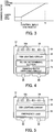
- the dimmer 4 changes a control input voltage serving as direct-current power to the dim lighting circuit 35 and the dimming control circuit 52 in a range of 0 V to 10 V according to the operation of the dimming setting section. As shown in FIG. 3 , the dimming ratio corresponding to the control input voltage is specified. When the control input voltage is 0 V, the dimming ratio is a lower limit dimming ratio (e.g., 20%).
- the dimming ratio is an upper limit dimming ratio of full lighting (e.g., 100%).
- the dimming ratio changes between the lower limit and the full lighting.
- a dimming signal (the control input voltage) of the dimming ratio set by the dimmer 46 is input to the dimming-signal input sections 39 of the lamp device 12 through the dimming control circuit 52.
- the dim lighting circuit 35 of the lamp device 12 dimly lights the light source 34 at the dimming ratio corresponding to the input dimming signal (control input Voltage).
- the wall switch 62 When the wall switch 62 is off, the supply of the commercial alternating-current power supply E to the lamp device 12 is cut off and the light source 34 of the lamp device 12 lights out.
- the commercial alternating-current power supply E is continuously supplied to the emergency unit 50. Therefore, the charging of the battery 54 is continued and the switching state of the relay switches 59 of the power-supply switching circuit 51 and the switching state of the relay switches 60 of the dimming control circuit 52 are maintained.
- the relay switches 59 of the power-supply switching circuit 51 change to the switching state for connecting the emergency unit 50 (the battery 54) to the power-supply input sections 38 of the lamp device 12.
- the relay switches 60 of the dimming control circuit 52 change to the switching state for separating the dimmer 46 from the dimming-signal input sections 39 of the lamp device 12 and short-circuiting the pair of dimming-signal input sections 39.
- the power-supply monitoring circuit 57 of the emergency unit 50 confirms the cut-off of the commercial alternating-current power supply E, whereby the DC/DC discharge circuit 56 converts the direct-current power supply of the battery 54 into the predetermined direct-current power supply and outputs the predetermined direct-current power supply.
- the direct-current power supply is input to the power-supply input sections 38 of the lamp device 12 through the power-supply switching circuit 51.
- the light source 34 is lit by the dim lighting circuit 35 of the lamp device 12.
- the light source 34 lit by the dim lighting circuit 35 of the lamp device 12 is dimly lit at brightness corresponding to the dimming ratio set by the dimming control circuit 52.
- the dim lighting circuit 35 of the lamp device 12 supplies the predetermined direct-current power to the dimming control circuit 52.
- the relay switches 60 short-circuit the pair of dimming-signal input sections 39 of the lamp device 12. Therefore, the control input voltage is 0 V.
- the dimming control circuit 52 controls the dimming ratio for an emergency to the lower limit dimming ratio (e.g., 20%).
- the dimming signal (the control input voltage) at the lower limit dimming ratio controlled by the dimming control circuit 52 is input to the dimming-signal input sections 39 of the lamp device 12.
- the dim lighting circuit 35 of the lamp device 12 dimly lights the light source 34 at the lower limit dimming ratio according to the input dimming signal (control input Voltage).
- the luminaire 10 In a normal time, the supply of the commercial alternating-current power supply E to the emergency unit 50 is cut off according to the operation of the inspection switch 18. Therefore, the luminaire 10 is in the same state as in an emergency. If expiration of the life of the battery 54, a failure of the emergency unit 50, or the like occurs, the lamp device 12 is not lit even if the inspection switch 18 is operated. Therefore, a deficiency can be confirmed.
- the power supply of the battery 54 of the emergency unit 50 is supplied to the lamp device 12 and the dimming signal of the dimming ratio in an emergency is given to the lamp device 12. Therefore, the lamp device 12 can light the light source 34 at the lower limit dimming ratio for an emergency. Therefore, it is possible to reduce the exhaustion of the battery 54 and satisfy the specified predetermined lighting time in an emergency.
- the commercial alternating-current power supply E is input to the lamp device 12 from the common power-supply input sections 38 in a normal time.
- the direct-current power supply is input to the lamp device 12 from the battery 54 in an emergency.
- the dim lighting circuit 35 can dimly light the light source 34 with either the alternating-current power supply or the direct-current power supply input to the common power-supply input sections 38. In general, such a lamp device 12 fully lights the light source 34 if the dimming signal is not input. Therefore, if the dimming signal is not input in an emergency, the light source 34 is fully lit by the power supply of the battery 54 and the battery 54 is exhausted early.
- the dimming control circuit 52 can give the dimming signal of the dimming ratio for an emergency to the lamp device 12. Therefore, the lamp device 12 can light the light source 34 at the lower limit dimming ratio for an emergency and reduce the exhaustion of the battery 54.
- the dimming ratio for an emergency is set to the lower limit dimming ratio in the range of dimming ratios at which dimming can be performed, it is possible to suppress the exhaustion of the battery 54 most.
- the dimming ratio for an emergency is not limited to the lower limit dimming ratio and may be set to a dimming ratio for an emergency for enabling the suppression of the exhaustion of the battery 54 in addition to satisfying the brightness.
- the emergency device 17 may be attached to the appliance device main body 15 or may be arranged in a place separate from the appliance device main body 15.
- the luminaire 10 according to a second embodiment is explained with reference to FIG. 4 .
- the dimming ratio in an emergency is set by the dimming control circuit 52 provided in the appliance device 11.
- the dimming ratio in an emergency may be set by providing an AC/DC determining circuit 71 and a dimming-ratio switching circuit 72 in the lamp device 12.
- the AC/DC determining circuit 71 is provided to be connected to the power-supply input sections 38 on the inside of the housing 33 of the lamp device 12.
- the dimming-ratio switching circuit 72 is provided to be connected to the dimming-signal input sections 39 on the inside of the housing 33 of the lamp device 12.
- the AC/DC determining circuit 71 and the dimming-ratio switching circuit 72 may be provided in the dim lighting circuit 35 or may be provided separately from the dim lighting circuit 35.
- the AC/DC determining circuit 71 determines which of the commercial alternating-current power supply E and the direct-current power supply from the emergency unit 50 the power supply supplied to the power-supply input sections 38 is. If the power supply is the supply of the commercial alternating-current power supply E, the dimming-ratio switching circuit 72 inputs the dimming signal input to the dimming-signal input sections 39 to the dim lighting circuit 35.
- the dimming-ratio switching circuit 72 inputs the dimming ratio for an emergency (e.g., 20%) set in advance in the dimming-ratio switching circuit 72 to the dim lighting circuit 35 rather than the dimming signal input to the dimming-signal input sections 39 from the dimmer 46. Therefore, in an emergency, the light source 34 is subjected to lighting control by the dim lighting circuit 35 at the dimming ratio for an emergency set in advance.
- an emergency e.g. 20%
- the luminaire 10 Even if the emergency device 17 does not include the dimming-signal input sections 47 and the dimming control circuit 52, since the AC/DC determining circuit 71 and the dimming-ratio switching circuit 72 are provided in the lamp device 12, in an emergency, it is possible to subject the light source 34 to lighting control at the dimming ratio for an emergency set in advance.
- the luminaire 10 according to a third embodiment is explained with reference to FIG. 5 .
- the emergency unit 50 for the luminaire 10 is provided in the emergency device 17.
- the emergency unit 50 may be provided in the lamp device 12.
- the battery 54 may be provided on the inside of the housing 33 of the lamp device 12 or may be provided on the outside of the housing 33. If the battery 54 is provided on the outside of the housing 33 of the lamp device 12, the battery 54 is suitably provided between the dimming-signal output sections 48 and the dimming-signal input sections 39. It is possible to facilitate replacement of the battery 54 by providing the battery 54 in this way. A supply path of the battery 54 and a transmission path of the dimming signal are provided in common. Therefore, it is possible to use the lamp device 12 and the luminaire 10 as an emergency luminaire without providing a new lamp pin in the lamp device 12.
Applications Claiming Priority (1)
| Application Number | Priority Date | Filing Date | Title |
|---|---|---|---|
| JP2011141568A JP2013008616A (ja) | 2011-06-27 | 2011-06-27 | 照明装置 |
Publications (1)
| Publication Number | Publication Date |
|---|---|
| EP2542028A1 true EP2542028A1 (en) | 2013-01-02 |
Family
ID=45819013
Family Applications (1)
| Application Number | Title | Priority Date | Filing Date |
|---|---|---|---|
| EP12157875A Withdrawn EP2542028A1 (en) | 2011-06-27 | 2012-03-02 | Luminaire with emergency lighting function |
Country Status (4)
| Country | Link |
|---|---|
| US (1) | US20120326614A1 (ja) |
| EP (1) | EP2542028A1 (ja) |
| JP (1) | JP2013008616A (ja) |
| CN (1) | CN102858051B (ja) |
Cited By (1)
| Publication number | Priority date | Publication date | Assignee | Title |
|---|---|---|---|---|
| US9999108B2 (en) | 2014-05-14 | 2018-06-12 | Philips Lighting Holding B.V. | Emergency lighting driver with programmable output power |
Families Citing this family (35)
| Publication number | Priority date | Publication date | Assignee | Title |
|---|---|---|---|---|
| US10655837B1 (en) | 2007-11-13 | 2020-05-19 | Silescent Lighting Corporation | Light fixture assembly having a heat conductive cover with sufficiently large surface area for improved heat dissipation |
| US9657930B2 (en) * | 2011-12-13 | 2017-05-23 | Ephesus Lighting, Inc. | High intensity light-emitting diode luminaire assembly |
| TWM439302U (en) * | 2012-05-04 | 2012-10-11 | Just Power Integrated Technology Inc | (3) has electrical detection device |
| US9581751B2 (en) | 2013-01-30 | 2017-02-28 | Cree, Inc. | Optical waveguide and lamp including same |
| US9442243B2 (en) | 2013-01-30 | 2016-09-13 | Cree, Inc. | Waveguide bodies including redirection features and methods of producing same |
| US9690029B2 (en) | 2013-01-30 | 2017-06-27 | Cree, Inc. | Optical waveguides and luminaires incorporating same |
| WO2014120969A1 (en) * | 2013-01-30 | 2014-08-07 | Cree, Inc. | Optical waveguide and luminaire incorporating same |
| US9366396B2 (en) | 2013-01-30 | 2016-06-14 | Cree, Inc. | Optical waveguide and lamp including same |
| US10234616B2 (en) | 2013-01-30 | 2019-03-19 | Cree, Inc. | Simplified low profile module with light guide for pendant, surface mount, wall mount and stand alone luminaires |
| US9291320B2 (en) | 2013-01-30 | 2016-03-22 | Cree, Inc. | Consolidated troffer |
| US9869432B2 (en) | 2013-01-30 | 2018-01-16 | Cree, Inc. | Luminaires using waveguide bodies and optical elements |
| US9625638B2 (en) | 2013-03-15 | 2017-04-18 | Cree, Inc. | Optical waveguide body |
| US9214834B1 (en) | 2013-03-13 | 2015-12-15 | Cooper Technologies Company | Automatic emergency lighting load control |
| US10209429B2 (en) | 2013-03-15 | 2019-02-19 | Cree, Inc. | Luminaire with selectable luminous intensity pattern |
| US10502899B2 (en) * | 2013-03-15 | 2019-12-10 | Ideal Industries Lighting Llc | Outdoor and/or enclosed structure LED luminaire |
| US10379278B2 (en) * | 2013-03-15 | 2019-08-13 | Ideal Industries Lighting Llc | Outdoor and/or enclosed structure LED luminaire outdoor and/or enclosed structure LED luminaire having outward illumination |
| US9366799B2 (en) | 2013-03-15 | 2016-06-14 | Cree, Inc. | Optical waveguide bodies and luminaires utilizing same |
| US10436970B2 (en) | 2013-03-15 | 2019-10-08 | Ideal Industries Lighting Llc | Shaped optical waveguide bodies |
| US9798072B2 (en) | 2013-03-15 | 2017-10-24 | Cree, Inc. | Optical element and method of forming an optical element |
| JP6395127B2 (ja) * | 2014-04-30 | 2018-09-26 | 岩崎電気株式会社 | 照明設備 |
| JP6323149B2 (ja) * | 2014-05-07 | 2018-05-16 | 岩崎電気株式会社 | 停電補償機能付き照明用電源装置及び照明装置 |
| CN105576814B (zh) * | 2014-10-13 | 2018-06-29 | 康舒科技股份有限公司 | 直流电源备援系统 |
| JP2016219385A (ja) * | 2015-05-26 | 2016-12-22 | パナソニックIpマネジメント株式会社 | 照明システム |
| GB2544562A (en) * | 2015-11-23 | 2017-05-24 | Hanslod Mohamed | LED light fitting and emergency power supply therefor |
| US10416377B2 (en) | 2016-05-06 | 2019-09-17 | Cree, Inc. | Luminaire with controllable light emission |
| US11719882B2 (en) | 2016-05-06 | 2023-08-08 | Ideal Industries Lighting Llc | Waveguide-based light sources with dynamic beam shaping |
| CN108879934A (zh) * | 2017-05-10 | 2018-11-23 | 深圳市其利顺光电有限公司 | 一种应急电源 |
| JP6851899B2 (ja) * | 2017-05-18 | 2021-03-31 | アール・ビー・コントロールズ株式会社 | Led照明装置 |
| US10944288B2 (en) * | 2017-08-24 | 2021-03-09 | Leon Hermans | Emergency power transfer switch system |
| US11509165B2 (en) * | 2017-08-24 | 2022-11-22 | Myers Emergency Power Systems Llc | Automatic transfer switch for lighting loads with integral load shedding by dimming control |
| US10344929B1 (en) | 2017-09-01 | 2019-07-09 | Heathco, Llc | Battery backup for lighting system |
| US11342833B2 (en) * | 2017-10-25 | 2022-05-24 | Hubbell Incorporated | Switch for a lighting system |
| JP7261974B2 (ja) * | 2018-02-05 | 2023-04-21 | パナソニックIpマネジメント株式会社 | 防災用照明器具 |
| CN111917171B (zh) * | 2020-07-15 | 2022-12-23 | 宁波荣特电子有限公司 | 一种高空灯应急电源系统 |
| US11476703B2 (en) * | 2021-02-26 | 2022-10-18 | Building Robotics, Inc. | Emergency lighting control bypass |
Citations (2)
| Publication number | Priority date | Publication date | Assignee | Title |
|---|---|---|---|---|
| EP1274286A1 (en) * | 2001-07-04 | 2003-01-08 | Teknoware Oy | Emergency lighting apparatus |
| DE102007040555A1 (de) * | 2007-08-28 | 2009-03-05 | Tridonicatco Gmbh & Co. Kg | Verfahren und Schaltung zum Identifizieren der Art einer Spannung, insbesondere der einem Betriebsgerät für Notlichtleuchten zugeführten Betriebsspannung |
Family Cites Families (16)
| Publication number | Priority date | Publication date | Assignee | Title |
|---|---|---|---|---|
| JP2000315590A (ja) * | 1999-04-30 | 2000-11-14 | Matsushita Electric Works Ltd | 照明装置 |
| DE10006408A1 (de) * | 2000-02-14 | 2001-08-16 | Zumtobel Staff Gmbh | Beleuchtungssystem |
| US20060146553A1 (en) * | 2004-10-08 | 2006-07-06 | B/E Aerospace, Inc. | Dimmable reading light with emergency lighting capability |
| US7414372B2 (en) * | 2005-10-24 | 2008-08-19 | International Rectifier Corporation | Dimming ballast control circuit |
| US8994276B2 (en) * | 2006-03-28 | 2015-03-31 | Wireless Environment, Llc | Grid shifting system for a lighting circuit |
| US9338839B2 (en) * | 2006-03-28 | 2016-05-10 | Wireless Environment, Llc | Off-grid LED power failure lights |
| CN101193483B (zh) * | 2006-11-23 | 2011-01-12 | 财团法人工业技术研究院 | 照明装置 |
| WO2010043923A1 (en) * | 2008-10-17 | 2010-04-22 | Osram Gesellschaft mit beschränkter Haftung | An emergency power supply circuit for dimmable electronic ballasts and related method |
| US8076867B2 (en) * | 2008-12-12 | 2011-12-13 | O2Micro, Inc. | Driving circuit with continuous dimming function for driving light sources |
| CN101686586B (zh) * | 2009-01-20 | 2012-09-12 | 深圳市众明半导体照明有限公司 | 一种应用于可控硅调光器的led调光装置 |
| CN201360175Y (zh) * | 2009-02-17 | 2009-12-09 | 天津光隆光电科技有限公司 | 一种led灯管电源切换电路 |
| US8248230B2 (en) * | 2009-02-20 | 2012-08-21 | Redwood Systems, Inc. | Smart power device |
| US8258705B2 (en) * | 2009-04-29 | 2012-09-04 | Hubbell Incorporated | Scotopically enhanced emergency light and control thereof |
| CN101707827B (zh) * | 2009-05-07 | 2012-12-26 | 海洋王照明科技股份有限公司 | 一种led灯具的电池电源控制方法及系统 |
| US8558407B2 (en) * | 2011-01-25 | 2013-10-15 | Man-D-Tec, Inc. | Elevator emergency LED lighting power supply assembly |
| US8823272B2 (en) * | 2011-12-12 | 2014-09-02 | Cree, Inc. | Emergency lighting systems including bidirectional booster/charger circuits |
-
2011
- 2011-06-27 JP JP2011141568A patent/JP2013008616A/ja active Pending
-
2012
- 2012-03-02 EP EP12157875A patent/EP2542028A1/en not_active Withdrawn
- 2012-03-05 US US13/411,758 patent/US20120326614A1/en not_active Abandoned
- 2012-03-22 CN CN201210077387.1A patent/CN102858051B/zh not_active Expired - Fee Related
Patent Citations (2)
| Publication number | Priority date | Publication date | Assignee | Title |
|---|---|---|---|---|
| EP1274286A1 (en) * | 2001-07-04 | 2003-01-08 | Teknoware Oy | Emergency lighting apparatus |
| DE102007040555A1 (de) * | 2007-08-28 | 2009-03-05 | Tridonicatco Gmbh & Co. Kg | Verfahren und Schaltung zum Identifizieren der Art einer Spannung, insbesondere der einem Betriebsgerät für Notlichtleuchten zugeführten Betriebsspannung |
Cited By (2)
| Publication number | Priority date | Publication date | Assignee | Title |
|---|---|---|---|---|
| US9999108B2 (en) | 2014-05-14 | 2018-06-12 | Philips Lighting Holding B.V. | Emergency lighting driver with programmable output power |
| US10404096B2 (en) | 2014-05-14 | 2019-09-03 | Signify Holding B.V. | Emergency lighting system |
Also Published As
| Publication number | Publication date |
|---|---|
| JP2013008616A (ja) | 2013-01-10 |
| CN102858051B (zh) | 2015-03-11 |
| CN102858051A (zh) | 2013-01-02 |
| US20120326614A1 (en) | 2012-12-27 |
Similar Documents
| Publication | Publication Date | Title |
|---|---|---|
| EP2542028A1 (en) | Luminaire with emergency lighting function | |
| CN109691229B (zh) | 从主电源和辅助电源供电的照明设备 | |
| JP5284734B2 (ja) | 携帯可能なledランプ | |
| JP2011119136A (ja) | Led照明装置 | |
| US20110163672A1 (en) | Light assembly | |
| TW201738503A (zh) | 具有電池備用功能之電燈 | |
| JP2013073706A (ja) | 照明装置 | |
| KR101580131B1 (ko) | 정전 시에도 사용 가능한 등기구 | |
| US10309596B2 (en) | Lighting apparatus including primary and secondary illumination sources and circuit controlling the same | |
| JP2012164436A (ja) | 照明器具 | |
| JP6437061B2 (ja) | 照明器具 | |
| JP2015232990A (ja) | 停電時点灯用のled照明装置 | |
| JP3176527U (ja) | Led電球 | |
| JP2010205440A (ja) | 照明システム | |
| JP2010040205A (ja) | 照明装置 | |
| JP4429143B2 (ja) | 照明器具 | |
| JP5812273B2 (ja) | 電源制御装置および照明システム | |
| JP6753318B2 (ja) | 照明装置 | |
| JP2009158214A (ja) | 非常用照明システム | |
| KR101089043B1 (ko) | 비상용 전원을 구비한 충전식 엘이디 랜턴 | |
| JP3193100U (ja) | 無停電電源検知装置 | |
| JP5520163B2 (ja) | 照明器具用保護装置、照明器具、給電用コネクタ、並びに、アダプタ | |
| JP5925367B2 (ja) | 照明装置 | |
| JP5748049B2 (ja) | 照明装置 | |
| JP3175935U (ja) | 無停電照明器具 |
Legal Events
| Date | Code | Title | Description |
|---|---|---|---|
| PUAI | Public reference made under article 153(3) epc to a published international application that has entered the european phase |
Free format text: ORIGINAL CODE: 0009012 |
|
| 17P | Request for examination filed |
Effective date: 20120302 |
|
| AK | Designated contracting states |
Kind code of ref document: A1 Designated state(s): AL AT BE BG CH CY CZ DE DK EE ES FI FR GB GR HR HU IE IS IT LI LT LU LV MC MK MT NL NO PL PT RO RS SE SI SK SM TR |
|
| AX | Request for extension of the european patent |
Extension state: BA ME |
|
| STAA | Information on the status of an ep patent application or granted ep patent |
Free format text: STATUS: THE APPLICATION HAS BEEN WITHDRAWN |
|
| 18W | Application withdrawn |
Effective date: 20150427 |