EP2540997A1 - Stufenlose, variable Ventileinsteuerungseinrichtung und Steuerungsverfahren dafür - Google Patents
Stufenlose, variable Ventileinsteuerungseinrichtung und Steuerungsverfahren dafür Download PDFInfo
- Publication number
- EP2540997A1 EP2540997A1 EP12167237A EP12167237A EP2540997A1 EP 2540997 A1 EP2540997 A1 EP 2540997A1 EP 12167237 A EP12167237 A EP 12167237A EP 12167237 A EP12167237 A EP 12167237A EP 2540997 A1 EP2540997 A1 EP 2540997A1
- Authority
- EP
- European Patent Office
- Prior art keywords
- cvvt
- suction
- lift
- continuously variable
- timing
- Prior art date
- Legal status (The legal status is an assumption and is not a legal conclusion. Google has not performed a legal analysis and makes no representation as to the accuracy of the status listed.)
- Granted
Links
Images


Classifications
-
- F—MECHANICAL ENGINEERING; LIGHTING; HEATING; WEAPONS; BLASTING
- F01—MACHINES OR ENGINES IN GENERAL; ENGINE PLANTS IN GENERAL; STEAM ENGINES
- F01L—CYCLICALLY OPERATING VALVES FOR MACHINES OR ENGINES
- F01L13/00—Modifications of valve-gear to facilitate reversing, braking, starting, changing compression ratio, or other specific operations
-
- F—MECHANICAL ENGINEERING; LIGHTING; HEATING; WEAPONS; BLASTING
- F01—MACHINES OR ENGINES IN GENERAL; ENGINE PLANTS IN GENERAL; STEAM ENGINES
- F01L—CYCLICALLY OPERATING VALVES FOR MACHINES OR ENGINES
- F01L1/00—Valve-gear or valve arrangements, e.g. lift-valve gear
- F01L1/34—Valve-gear or valve arrangements, e.g. lift-valve gear characterised by the provision of means for changing the timing of the valves without changing the duration of opening and without affecting the magnitude of the valve lift
- F01L1/344—Valve-gear or valve arrangements, e.g. lift-valve gear characterised by the provision of means for changing the timing of the valves without changing the duration of opening and without affecting the magnitude of the valve lift changing the angular relationship between crankshaft and camshaft, e.g. using helicoidal gear
- F01L1/3442—Valve-gear or valve arrangements, e.g. lift-valve gear characterised by the provision of means for changing the timing of the valves without changing the duration of opening and without affecting the magnitude of the valve lift changing the angular relationship between crankshaft and camshaft, e.g. using helicoidal gear using hydraulic chambers with variable volume to transmit the rotating force
-
- F—MECHANICAL ENGINEERING; LIGHTING; HEATING; WEAPONS; BLASTING
- F01—MACHINES OR ENGINES IN GENERAL; ENGINE PLANTS IN GENERAL; STEAM ENGINES
- F01L—CYCLICALLY OPERATING VALVES FOR MACHINES OR ENGINES
- F01L1/00—Valve-gear or valve arrangements, e.g. lift-valve gear
- F01L1/34—Valve-gear or valve arrangements, e.g. lift-valve gear characterised by the provision of means for changing the timing of the valves without changing the duration of opening and without affecting the magnitude of the valve lift
-
- F—MECHANICAL ENGINEERING; LIGHTING; HEATING; WEAPONS; BLASTING
- F01—MACHINES OR ENGINES IN GENERAL; ENGINE PLANTS IN GENERAL; STEAM ENGINES
- F01L—CYCLICALLY OPERATING VALVES FOR MACHINES OR ENGINES
- F01L13/00—Modifications of valve-gear to facilitate reversing, braking, starting, changing compression ratio, or other specific operations
- F01L13/0015—Modifications of valve-gear to facilitate reversing, braking, starting, changing compression ratio, or other specific operations for optimising engine performances by modifying valve lift according to various working parameters, e.g. rotational speed, load, torque
- F01L13/0021—Modifications of valve-gear to facilitate reversing, braking, starting, changing compression ratio, or other specific operations for optimising engine performances by modifying valve lift according to various working parameters, e.g. rotational speed, load, torque by modification of rocker arm ratio
- F01L13/0026—Modifications of valve-gear to facilitate reversing, braking, starting, changing compression ratio, or other specific operations for optimising engine performances by modifying valve lift according to various working parameters, e.g. rotational speed, load, torque by modification of rocker arm ratio by means of an eccentric
-
- F—MECHANICAL ENGINEERING; LIGHTING; HEATING; WEAPONS; BLASTING
- F02—COMBUSTION ENGINES; HOT-GAS OR COMBUSTION-PRODUCT ENGINE PLANTS
- F02D—CONTROLLING COMBUSTION ENGINES
- F02D13/00—Controlling the engine output power by varying inlet or exhaust valve operating characteristics, e.g. timing
- F02D13/02—Controlling the engine output power by varying inlet or exhaust valve operating characteristics, e.g. timing during engine operation
-
- F—MECHANICAL ENGINEERING; LIGHTING; HEATING; WEAPONS; BLASTING
- F01—MACHINES OR ENGINES IN GENERAL; ENGINE PLANTS IN GENERAL; STEAM ENGINES
- F01L—CYCLICALLY OPERATING VALVES FOR MACHINES OR ENGINES
- F01L1/00—Valve-gear or valve arrangements, e.g. lift-valve gear
- F01L1/34—Valve-gear or valve arrangements, e.g. lift-valve gear characterised by the provision of means for changing the timing of the valves without changing the duration of opening and without affecting the magnitude of the valve lift
- F01L1/344—Valve-gear or valve arrangements, e.g. lift-valve gear characterised by the provision of means for changing the timing of the valves without changing the duration of opening and without affecting the magnitude of the valve lift changing the angular relationship between crankshaft and camshaft, e.g. using helicoidal gear
- F01L1/3442—Valve-gear or valve arrangements, e.g. lift-valve gear characterised by the provision of means for changing the timing of the valves without changing the duration of opening and without affecting the magnitude of the valve lift changing the angular relationship between crankshaft and camshaft, e.g. using helicoidal gear using hydraulic chambers with variable volume to transmit the rotating force
- F01L2001/3445—Details relating to the hydraulic means for changing the angular relationship
- F01L2001/34483—Phaser return springs
-
- F—MECHANICAL ENGINEERING; LIGHTING; HEATING; WEAPONS; BLASTING
- F01—MACHINES OR ENGINES IN GENERAL; ENGINE PLANTS IN GENERAL; STEAM ENGINES
- F01L—CYCLICALLY OPERATING VALVES FOR MACHINES OR ENGINES
- F01L13/00—Modifications of valve-gear to facilitate reversing, braking, starting, changing compression ratio, or other specific operations
- F01L13/0015—Modifications of valve-gear to facilitate reversing, braking, starting, changing compression ratio, or other specific operations for optimising engine performances by modifying valve lift according to various working parameters, e.g. rotational speed, load, torque
- F01L13/0063—Modifications of valve-gear to facilitate reversing, braking, starting, changing compression ratio, or other specific operations for optimising engine performances by modifying valve lift according to various working parameters, e.g. rotational speed, load, torque by modification of cam contact point by displacing an intermediate lever or wedge-shaped intermediate element, e.g. Tourtelot
- F01L2013/0068—Modifications of valve-gear to facilitate reversing, braking, starting, changing compression ratio, or other specific operations for optimising engine performances by modifying valve lift according to various working parameters, e.g. rotational speed, load, torque by modification of cam contact point by displacing an intermediate lever or wedge-shaped intermediate element, e.g. Tourtelot with an oscillating cam acting on the valve of the "BMW-Valvetronic" type
-
- F—MECHANICAL ENGINEERING; LIGHTING; HEATING; WEAPONS; BLASTING
- F01—MACHINES OR ENGINES IN GENERAL; ENGINE PLANTS IN GENERAL; STEAM ENGINES
- F01L—CYCLICALLY OPERATING VALVES FOR MACHINES OR ENGINES
- F01L13/00—Modifications of valve-gear to facilitate reversing, braking, starting, changing compression ratio, or other specific operations
- F01L13/0015—Modifications of valve-gear to facilitate reversing, braking, starting, changing compression ratio, or other specific operations for optimising engine performances by modifying valve lift according to various working parameters, e.g. rotational speed, load, torque
- F01L13/0063—Modifications of valve-gear to facilitate reversing, braking, starting, changing compression ratio, or other specific operations for optimising engine performances by modifying valve lift according to various working parameters, e.g. rotational speed, load, torque by modification of cam contact point by displacing an intermediate lever or wedge-shaped intermediate element, e.g. Tourtelot
- F01L2013/0073—Modifications of valve-gear to facilitate reversing, braking, starting, changing compression ratio, or other specific operations for optimising engine performances by modifying valve lift according to various working parameters, e.g. rotational speed, load, torque by modification of cam contact point by displacing an intermediate lever or wedge-shaped intermediate element, e.g. Tourtelot with an oscillating cam acting on the valve of the "Delphi" type
Definitions
- the present invention relates to a continuously variable valve timing system and a method for controlling the same, and more particularly, to a continuously variable valve timing system and a method for controlling the same which can improve a fuel efficiency by controlling a reference position when a general hydraulic CVVT (continuously variable valve timing) system is employed in a continuously variable valve lift (CVVL) engine having no self-advanced/delayed angle function.
- CVVT continuously variable valve timing
- CVVL continuously variable valve lift
- ECU electronice control unit
- a valve lift changing property of the CVVL system is varied depending upon the structure of the variable lift mechanism of the CVVL engine.
- the valve lift changing property can be divided into two types described below, depending upon whether the maximum opening point (MOP) is varied or not when the valve lift is changed.
- MOP maximum opening point
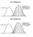
- FIG. 1 is a view illustrating a lift changing property of a CVVL system having no self-advanced/delayed angle function.
- FIG. 2 is a view illustrating a lift changing property of a CVVL system having a self-advanced/delayed angle function.
- FIGS. 1 and 2 show the change in suction valve lift profile at a valve lift variation according to the presence or absence of the self-advanced/delayed angle function.
- the CVVL system having no self-advanced/delayed angle function is a system in which the MOP is not changed by the operation of the CVVL mechanism when the valve lift is changed.
- the structure thereof is relatively simple, which is preferable to CVVL embodiment, but the cam timing is controlled by a separate CVVT system.
- the CVVL system having the self-advanced/delayed angle function is a system in which the MOP is changed by the operation of the CVVL mechanism when the valve lift is changed. If the advanced/delayed angle property of the CVVL mechanism is utilized, it can share a portion of separate CVVT operating necessity.
- a suction/exhaust cam timing is controlled to minimize a fuel consuming amount under driving conditions.
- a reference position is selected on the basis of the optimum cam timing in a low-speed and low-load region including start and idle, and generally corresponds to a suction/exhaust timing at which the value overlap is minimized.
- the reference position of the suction cam timing is the most delayed angle position, while the reference position of the exhaust cam timing is the most advanced angle position.
- the reference position should be maintained under a condition in which the oil pressure sufficient for driving the CVVT is not generated at start and low-speed driving.
- the optimum cam timing should be shifted in such a manner that the suction is shifted to the advanced angle direction and the exhaust timing is shifted to the delayed angle direction, in relation to the idle cam timing.
- the oil pressure created in a head oil gallery is respectively applied to the advanced angle chamber and the delayed angle chamber in the CVVT apparatus by an oil control valve (OCV) through two oil circuits (advanced angle oil passage and delayed angle oil passage).
- OCV oil control valve
- the CVVT is operated against the resilient force of the bias spring by the pressure difference between the advanced angle chamber and the delayed angle chamber.
- the suction/exhaust cam timing can be varied.
- the CVVT is not operated due to the lack of the oil pressure, and the suction/exhaust CVVT should be operated in the reference position (suction most delayed angle and exhaust most advanced angle).
- the fuel efficiency is deteriorated due to the increased pumping loss and the increased effective compression ratio.
- Various aspects of the present invention are directed to providing a continuously variable valve timing system and a method for controlling the same, which improves a method for controlling selection of a reference position of a CVVT (continuously variable valve timing) in a general Non-CVVL engine and a CVVL (continuously variable valve lift) engine when a general hydraulic CVVL system is employed in the CVVL engine having no self-advanced/delayed angle function, thereby reducing a pumping loss and thus improving a fuel efficiency and an effective compression ratio to improve a knock property and reduce variations of RPM in a cycle.
- CVVT continuously variable valve timing
- CVVL continuously variable valve lift
- a method for controlling a continuously variable valve timing (CVVT) system which is operated in cooperation with a continuously variable valve lift (CVVL) engine, including the steps of, setting a reference position of a suction CVVT to a most advanced angle position controlling a delayed angle amount at the reference position of the most advanced angle.
- CVVT continuously variable valve timing
- CVVL continuously variable valve lift
- the present invention can set a low valve lift and optimum cam timing, which is necessary for the same in a low RPM region including an idle condition, as a reference position. Therefore, the optimum valve lift can be used in the region without employing the CVVT control, thereby improving the fuel efficiency in the idle and low-speed region. In addition, a proper effective compression ratio is maintained to suppress generation of knock and decrease variations of RPM.
- the valve lift is changed, it is possible to improve the fuel efficiency at the low speed, without complicating the mechanism required to employ the CVVL mechanism having the self-advanced/delayed angle function and increasing rotational inertial and friction, as well as a cost.
- the combination of the valve lift and the cam timing optimized for various driving conditions can be achieved by using the general hydraulic CVVT module to improve a merchantable quality.
- FIG. 1 is a view illustrating a lift changing property of a CVVL system having no self-advanced/delayed angle function.
- FIG. 2 is a view illustrating a lift changing property of a CVVL system having a self-advanced/delayed angle function.
- FIG. 3 is a view illustrating the structure of a hydraulic CVVT system in the related art.
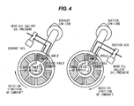
- FIG. 4 is a view illustrating the structure of a hydraulic CVVT system according to an exemplary embodiment of the present invention.
- FIG. 5 is a graph illustrating the efficiency based on a valve lift and a suction cam timing.
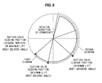
- FIG. 6 is a view illustrating an optimum valve lift and a suction timing in a continuously variable valve lift engine.
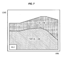
- FIG. 7 is a view illustrating the optimum valve lift and the suction timing for each driving condition.
- FIG. 8 is a view illustrating properties of the optimum valve lift and the suction timing.
- FIG. 9 is a view illustrating an effective compression ratio and a RAM variation according to a lift/suction cam.
- FIGS. 4 to 9 are views illustrating a continuously variable valve timing system and a method of controlling the same according to an exemplary embodiment of the present invention.
- FIG. 4 is a view illustrating the structure of a hydraulic CVVT system according to an exemplary embodiment of the present invention.
- FIG. 5 is a graph illustrating the efficiency based on a valve lift and a suction cam timing.
- FIG. 6 is a view illustrating an optimum valve lift and a suction timing in a continuously variable valve lift engine.
- FIG. 7 is a view illustrating the optimum valve lift and the suction timing for each driving condition.
- FIG. 8 is a view illustrating properties of the optimum valve lift and the suction timing.
- FIG. 9 is a view illustrating an effective compression ratio and a RAM variation according to a lift/suction cam.
- controlling a dimension of a valve lift continuously and variably is to minimize a pumping loss and thus improve a fuel efficiency. Since the valve lift and a valve opening duration can be variably controlled in the CVVL engine, the engine can be operated by selecting a suction valve opening position and a suction valve closing position to have an optimum value in cooperation with a CVVT mechanism.
- the pumping loss is theoretically zero to a piston position during a suction valve closing timing, the pumping loss is minimized by suctioning an air volume corresponding to a volume of a combustion chamber for the suction valve closing duration.
- the suction valve closing position is significantly shifted to an advanced angle in the general Non-CVVL engine having a constant valve lift and valve closing direction, the suction valve opening timing is significantly shifted to the advanced angle, and thus the valve overlap becomes excessively large, so that misfire occurs due to unstable combustion, which is a condition which cannot drive a vehicle.
- a first diagram indicates a combustion pressure and a volume at a maximum lift (valve lift which is equal to MP1)
- a second diagram indicates a combustion pressure and a volume at a minimum lift (throttle minimizing lift by a throttle body).
- the pumping loss in comparison to the pumping loss (area of a border portion of the first diagram) in the case of using the maximum lift, the pumping loss (area of red border portion) in the case of using the minimum lift is varied depending upon the minimum lift, but when the minimum lift is 1 mm, the pumping loss can be reduced by 1/3 of the Non-CVVL (or the maximum lift). It can reduce an indicated mean effective pressure (IMEP) and fuel consumption, thereby improving the fuel efficiency.
- IMEP mean effective pressure
- FIGS. 7 and 8 show the optimum valve lift and a suction timing property, in which the below engine driving property is obtained according to the lift and the suction cam.
- the pumping loss is minimized and the fuel efficiency is improved. If the lift is minimum and the suction cam is at the most delayed angle, the effective compression ratio is excessive, knocking occurs, and an RPM variation in the cycle is excessive. If the lift is maximum and the suction cam is the most advanced angle, the inner EGR is excessive, and the combustion stability is deteriorated. If the lift is maximum and the suction cam is at the most delayed angle, the high-speed output is increased.
- the minimum lift and the most advanced angle suction cam timing should be used.
- the suction cam timing is fixed to the most delayed angle condition. In this instance, the pumping loss can be reduced by using the maximum lift instead of the minimum lift, but the fuel efficiency is deteriorated in comparison with the minimum lift and the most advanced angle suction cam.
- the minimum lift and the most advanced angle suction cam timing are required in a partial-load region which is an important region, as well as the idle region. In this instance, as the load is increased, the lift is increased and the suction cam timing is slightly delayed.
- the CVVL engine having a self-advanced angle function has an effect of obtaining the advanced angle of the opening/closing timing and a valve profile through reduction of the lift, but the CVVL engine having no self-advanced angle function should have the optimum cam timing by the control and operation of the CVVT.
- the CVVT system capable of obtaining the optimum cam timing in the CVVL engine according to an exemplary embodiment of the present invention, and the method for controlling the same will be described.
- the optimum fuel efficiency, drivability and performance can be satisfied by simultaneously obtaining the optimum lift and cam timing for every engine driving region. It can be seen that CVVT requirements at the low speed are different from those of the general Non-CVVL engine.
- the present invention relates to the hydraulic control CVVT for driving the optimum cam timing for every valve lift in the CVVL engine having no self-advanced/delayed angle function or remarkably insufficient advanced/delayed angle amount, as compared with the necessary advanced/delayed angle amount, when the valve lift is varied.
- a reference position of the suction CVVT is set to the most advanced angle position, and a CVVT assembly with a bias spring to control the delayed angle amount at the reference position of the most advanced angle.
- the reference position of the suction CVVT in the CVVT system which operates in cooperation with the CVVL engine is set by the spring.
- the CVVT system In order to set the reference position of the suction CVVT to the most advanced angle position and control the delayed angle of the CVVT, the CVVT system is provided with the bias spring so that the suction cam timing is shifted in an advanced angle direction when an oil control valve installed in the CVVT system does not operate (when PWM is zero).
- the oil control valve installed in the CVVT system operates to the max (when PWM is applied)
- the cam timing is shifted to the advanced angle position by the resilience force of the bias spring.
- the position of the CVVT can be fixed by using a lock pin, like a general CVVT module. If the oil control valve is operated after the oil pressure is created, the oil pressure is applied to the delayed angle chamber of the CVVT module through the oil control valve and the oil circuit. The delayed angle chamber is connected to a drain passage through the oil control valve, and thus the cam timing is shifted in the advanced angle direction by the oil pressure difference in the advanced angle chamber and the delayed angle chamber.
- the reference position of the suction CVVT is set to the most advanced angle position in the CVVT system which is operated in cooperation with the CVVL engine. After that, the delayed angle amount is controlled at the reference position of the advanced angle to improve the fuel efficiency at the low speed and increase the merchantable quality.
Landscapes
- Engineering & Computer Science (AREA)
- Mechanical Engineering (AREA)
- General Engineering & Computer Science (AREA)
- Chemical & Material Sciences (AREA)
- Combustion & Propulsion (AREA)
- Output Control And Ontrol Of Special Type Engine (AREA)
- Valve Device For Special Equipments (AREA)
Applications Claiming Priority (1)
| Application Number | Priority Date | Filing Date | Title |
|---|---|---|---|
| KR1020110063011A KR101262532B1 (ko) | 2011-06-28 | 2011-06-28 | 연속가변밸브타이밍 시스템 및 제어방법 |
Publications (2)
| Publication Number | Publication Date |
|---|---|
| EP2540997A1 true EP2540997A1 (de) | 2013-01-02 |
| EP2540997B1 EP2540997B1 (de) | 2015-10-07 |
Family
ID=46146655
Family Applications (1)
| Application Number | Title | Priority Date | Filing Date |
|---|---|---|---|
| EP12167237.2A Active EP2540997B1 (de) | 2011-06-28 | 2012-05-09 | Stufenloses variables Ventileinsteuerungseinrichtung und Steuerungsverfahren dafür |
Country Status (3)
| Country | Link |
|---|---|
| US (1) | US20130000575A1 (de) |
| EP (1) | EP2540997B1 (de) |
| KR (1) | KR101262532B1 (de) |
Families Citing this family (5)
| Publication number | Priority date | Publication date | Assignee | Title |
|---|---|---|---|---|
| KR101448794B1 (ko) | 2013-07-02 | 2014-10-08 | 현대자동차 주식회사 | 오일 컨트롤 밸브의 전류 제어에 따른 연속 가변 밸브 타이밍 제어 방법 |
| KR101558352B1 (ko) | 2013-10-14 | 2015-10-07 | 현대자동차 주식회사 | 가변 밸브 타이밍 기구를 갖는 엔진의 제어방법 |
| US20160363010A1 (en) | 2015-06-09 | 2016-12-15 | Hyundai Motor Company | Method of controlling intermediate phase cvvt |
| US9617925B2 (en) * | 2015-07-07 | 2017-04-11 | Hyundai Motor Company | Control method using continuous variable valve duration apparatus |
| KR102417382B1 (ko) * | 2016-12-14 | 2022-07-06 | 현대자동차주식회사 | 가변 밸브 타이밍 기구 및 가변 밸브 듀레이션 기구를 이용한 밸브 타이밍 및 밸브 듀레이션 제어 방법 |
Citations (2)
| Publication number | Priority date | Publication date | Assignee | Title |
|---|---|---|---|---|
| US20100050965A1 (en) * | 2008-09-01 | 2010-03-04 | Hitachi Automative Systems, Ltd. | Variable valve control apparatus |
| US20100116231A1 (en) * | 2008-11-12 | 2010-05-13 | Hitoshi Toda | Variable valve gear for internal combustion engine |
Family Cites Families (4)
| Publication number | Priority date | Publication date | Assignee | Title |
|---|---|---|---|---|
| JP2006307656A (ja) * | 2005-04-26 | 2006-11-09 | Hitachi Ltd | 圧縮着火エンジンの可変動弁システム |
| JP2008088928A (ja) * | 2006-10-04 | 2008-04-17 | Toyota Motor Corp | 内燃機関の可変バルブタイミング制御装置 |
| JP4858729B2 (ja) * | 2008-11-12 | 2012-01-18 | 三菱自動車工業株式会社 | 可変動弁装置 |
| JP4725655B2 (ja) | 2009-02-09 | 2011-07-13 | 株式会社デンソー | バルブタイミング調整装置 |
-
2011
- 2011-06-28 KR KR1020110063011A patent/KR101262532B1/ko active IP Right Grant
- 2011-12-29 US US13/339,832 patent/US20130000575A1/en not_active Abandoned
-
2012
- 2012-05-09 EP EP12167237.2A patent/EP2540997B1/de active Active
Patent Citations (2)
| Publication number | Priority date | Publication date | Assignee | Title |
|---|---|---|---|---|
| US20100050965A1 (en) * | 2008-09-01 | 2010-03-04 | Hitachi Automative Systems, Ltd. | Variable valve control apparatus |
| US20100116231A1 (en) * | 2008-11-12 | 2010-05-13 | Hitoshi Toda | Variable valve gear for internal combustion engine |
Also Published As
| Publication number | Publication date |
|---|---|
| US20130000575A1 (en) | 2013-01-03 |
| KR20130002029A (ko) | 2013-01-07 |
| EP2540997B1 (de) | 2015-10-07 |
| KR101262532B1 (ko) | 2013-05-08 |
Similar Documents
| Publication | Publication Date | Title |
|---|---|---|
| KR101396736B1 (ko) | 가변 밸브 기어를 구비한 내연 기관 | |
| US6840201B2 (en) | Variable valve timing control apparatus and method for an internal combustion engine | |
| JP4661461B2 (ja) | 可変圧縮比機構を備えた内燃機関 | |
| EP2540997B1 (de) | Stufenloses variables Ventileinsteuerungseinrichtung und Steuerungsverfahren dafür | |
| KR20100096025A (ko) | 가변 밸브 기어를 구비한 내연 기관 | |
| JP4858729B2 (ja) | 可変動弁装置 | |
| JPH086568B2 (ja) | エンジンの弁作動制御装置 | |
| JPH04246249A (ja) | 内燃機関の実圧縮比制御装置 | |
| US10697378B2 (en) | Control system of miller cycle engine and method of controlling miller cycle engine | |
| KR101204558B1 (ko) | 내연 기관용 가변 밸브 장치 | |
| JP4696946B2 (ja) | エンジンの吸気制御装置 | |
| US8635988B2 (en) | Variable valve device for internal combustion engine | |
| JP2007218114A5 (de) | ||
| JP4506414B2 (ja) | 内燃機関のバルブ特性制御装置 | |
| JP4049092B2 (ja) | 動弁装置 | |
| US20140165959A1 (en) | Engine having variable valve timing device and variable tumble device | |
| JP4389555B2 (ja) | 可変圧縮比内燃機関の制御装置 | |
| JP2007056796A (ja) | 可変圧縮比機構を備えた内燃機関 | |
| JP2007162664A (ja) | 内燃機関のバルブ作用角可変制御装置 | |
| JP4258453B2 (ja) | 内燃機関の吸気制御装置 | |
| JP4640120B2 (ja) | 内燃機関の制御装置 | |
| JP2009150320A (ja) | 内燃機関の可変動弁システム | |
| JP2009216035A (ja) | 内燃機関の制御装置 | |
| KR101136704B1 (ko) | 내연 기관의 가변 밸브 구동 장치 | |
| JP2005220754A (ja) | 可変圧縮比機構を備えた内燃機関 |
Legal Events
| Date | Code | Title | Description |
|---|---|---|---|
| PUAI | Public reference made under article 153(3) epc to a published international application that has entered the european phase |
Free format text: ORIGINAL CODE: 0009012 |
|
| AK | Designated contracting states |
Kind code of ref document: A1 Designated state(s): AL AT BE BG CH CY CZ DE DK EE ES FI FR GB GR HR HU IE IS IT LI LT LU LV MC MK MT NL NO PL PT RO RS SE SI SK SM TR |
|
| AX | Request for extension of the european patent |
Extension state: BA ME |
|
| 17P | Request for examination filed |
Effective date: 20130507 |
|
| RBV | Designated contracting states (corrected) |
Designated state(s): AL AT BE BG CH CY CZ DE DK EE ES FI FR GB GR HR HU IE IS IT LI LT LU LV MC MK MT NL NO PL PT RO RS SE SI SK SM TR |
|
| 17Q | First examination report despatched |
Effective date: 20140110 |
|
| GRAP | Despatch of communication of intention to grant a patent |
Free format text: ORIGINAL CODE: EPIDOSNIGR1 |
|
| INTG | Intention to grant announced |
Effective date: 20150416 |
|
| GRAS | Grant fee paid |
Free format text: ORIGINAL CODE: EPIDOSNIGR3 |
|
| GRAA | (expected) grant |
Free format text: ORIGINAL CODE: 0009210 |
|
| AK | Designated contracting states |
Kind code of ref document: B1 Designated state(s): AL AT BE BG CH CY CZ DE DK EE ES FI FR GB GR HR HU IE IS IT LI LT LU LV MC MK MT NL NO PL PT RO RS SE SI SK SM TR |
|
| REG | Reference to a national code |
Ref country code: GB Ref legal event code: FG4D |
|
| REG | Reference to a national code |
Ref country code: AT Ref legal event code: REF Ref document number: 753899 Country of ref document: AT Kind code of ref document: T Effective date: 20151015 Ref country code: CH Ref legal event code: EP |
|
| REG | Reference to a national code |
Ref country code: IE Ref legal event code: FG4D |
|
| REG | Reference to a national code |
Ref country code: DE Ref legal event code: R096 Ref document number: 602012011269 Country of ref document: DE |
|
| REG | Reference to a national code |
Ref country code: NL Ref legal event code: MP Effective date: 20151007 |
|
| REG | Reference to a national code |
Ref country code: AT Ref legal event code: MK05 Ref document number: 753899 Country of ref document: AT Kind code of ref document: T Effective date: 20151007 |
|
| REG | Reference to a national code |
Ref country code: LT Ref legal event code: MG4D |
|
| REG | Reference to a national code |
Ref country code: FR Ref legal event code: PLFP Year of fee payment: 5 |
|
| PG25 | Lapsed in a contracting state [announced via postgrant information from national office to epo] |
Ref country code: HR Free format text: LAPSE BECAUSE OF FAILURE TO SUBMIT A TRANSLATION OF THE DESCRIPTION OR TO PAY THE FEE WITHIN THE PRESCRIBED TIME-LIMIT Effective date: 20151007 Ref country code: NO Free format text: LAPSE BECAUSE OF FAILURE TO SUBMIT A TRANSLATION OF THE DESCRIPTION OR TO PAY THE FEE WITHIN THE PRESCRIBED TIME-LIMIT Effective date: 20160107 Ref country code: IT Free format text: LAPSE BECAUSE OF FAILURE TO SUBMIT A TRANSLATION OF THE DESCRIPTION OR TO PAY THE FEE WITHIN THE PRESCRIBED TIME-LIMIT Effective date: 20151007 Ref country code: NL Free format text: LAPSE BECAUSE OF FAILURE TO SUBMIT A TRANSLATION OF THE DESCRIPTION OR TO PAY THE FEE WITHIN THE PRESCRIBED TIME-LIMIT Effective date: 20151007 Ref country code: LT Free format text: LAPSE BECAUSE OF FAILURE TO SUBMIT A TRANSLATION OF THE DESCRIPTION OR TO PAY THE FEE WITHIN THE PRESCRIBED TIME-LIMIT Effective date: 20151007 Ref country code: ES Free format text: LAPSE BECAUSE OF FAILURE TO SUBMIT A TRANSLATION OF THE DESCRIPTION OR TO PAY THE FEE WITHIN THE PRESCRIBED TIME-LIMIT Effective date: 20151007 Ref country code: IS Free format text: LAPSE BECAUSE OF FAILURE TO SUBMIT A TRANSLATION OF THE DESCRIPTION OR TO PAY THE FEE WITHIN THE PRESCRIBED TIME-LIMIT Effective date: 20160207 |
|
| PG25 | Lapsed in a contracting state [announced via postgrant information from national office to epo] |
Ref country code: RS Free format text: LAPSE BECAUSE OF FAILURE TO SUBMIT A TRANSLATION OF THE DESCRIPTION OR TO PAY THE FEE WITHIN THE PRESCRIBED TIME-LIMIT Effective date: 20151007 Ref country code: AT Free format text: LAPSE BECAUSE OF FAILURE TO SUBMIT A TRANSLATION OF THE DESCRIPTION OR TO PAY THE FEE WITHIN THE PRESCRIBED TIME-LIMIT Effective date: 20151007 Ref country code: LV Free format text: LAPSE BECAUSE OF FAILURE TO SUBMIT A TRANSLATION OF THE DESCRIPTION OR TO PAY THE FEE WITHIN THE PRESCRIBED TIME-LIMIT Effective date: 20151007 Ref country code: SE Free format text: LAPSE BECAUSE OF FAILURE TO SUBMIT A TRANSLATION OF THE DESCRIPTION OR TO PAY THE FEE WITHIN THE PRESCRIBED TIME-LIMIT Effective date: 20151007 Ref country code: GR Free format text: LAPSE BECAUSE OF FAILURE TO SUBMIT A TRANSLATION OF THE DESCRIPTION OR TO PAY THE FEE WITHIN THE PRESCRIBED TIME-LIMIT Effective date: 20160108 Ref country code: PL Free format text: LAPSE BECAUSE OF FAILURE TO SUBMIT A TRANSLATION OF THE DESCRIPTION OR TO PAY THE FEE WITHIN THE PRESCRIBED TIME-LIMIT Effective date: 20151007 Ref country code: PT Free format text: LAPSE BECAUSE OF FAILURE TO SUBMIT A TRANSLATION OF THE DESCRIPTION OR TO PAY THE FEE WITHIN THE PRESCRIBED TIME-LIMIT Effective date: 20160208 Ref country code: FI Free format text: LAPSE BECAUSE OF FAILURE TO SUBMIT A TRANSLATION OF THE DESCRIPTION OR TO PAY THE FEE WITHIN THE PRESCRIBED TIME-LIMIT Effective date: 20151007 |
|
| REG | Reference to a national code |
Ref country code: DE Ref legal event code: R097 Ref document number: 602012011269 Country of ref document: DE |
|
| PG25 | Lapsed in a contracting state [announced via postgrant information from national office to epo] |
Ref country code: CZ Free format text: LAPSE BECAUSE OF FAILURE TO SUBMIT A TRANSLATION OF THE DESCRIPTION OR TO PAY THE FEE WITHIN THE PRESCRIBED TIME-LIMIT Effective date: 20151007 |
|
| PLBE | No opposition filed within time limit |
Free format text: ORIGINAL CODE: 0009261 |
|
| STAA | Information on the status of an ep patent application or granted ep patent |
Free format text: STATUS: NO OPPOSITION FILED WITHIN TIME LIMIT |
|
| PG25 | Lapsed in a contracting state [announced via postgrant information from national office to epo] |
Ref country code: EE Free format text: LAPSE BECAUSE OF FAILURE TO SUBMIT A TRANSLATION OF THE DESCRIPTION OR TO PAY THE FEE WITHIN THE PRESCRIBED TIME-LIMIT Effective date: 20151007 Ref country code: BE Free format text: LAPSE BECAUSE OF NON-PAYMENT OF DUE FEES Effective date: 20160531 Ref country code: SK Free format text: LAPSE BECAUSE OF FAILURE TO SUBMIT A TRANSLATION OF THE DESCRIPTION OR TO PAY THE FEE WITHIN THE PRESCRIBED TIME-LIMIT Effective date: 20151007 Ref country code: SM Free format text: LAPSE BECAUSE OF FAILURE TO SUBMIT A TRANSLATION OF THE DESCRIPTION OR TO PAY THE FEE WITHIN THE PRESCRIBED TIME-LIMIT Effective date: 20151007 Ref country code: DK Free format text: LAPSE BECAUSE OF FAILURE TO SUBMIT A TRANSLATION OF THE DESCRIPTION OR TO PAY THE FEE WITHIN THE PRESCRIBED TIME-LIMIT Effective date: 20151007 Ref country code: RO Free format text: LAPSE BECAUSE OF FAILURE TO SUBMIT A TRANSLATION OF THE DESCRIPTION OR TO PAY THE FEE WITHIN THE PRESCRIBED TIME-LIMIT Effective date: 20151007 |
|
| 26N | No opposition filed |
Effective date: 20160708 |
|
| PG25 | Lapsed in a contracting state [announced via postgrant information from national office to epo] |
Ref country code: SI Free format text: LAPSE BECAUSE OF FAILURE TO SUBMIT A TRANSLATION OF THE DESCRIPTION OR TO PAY THE FEE WITHIN THE PRESCRIBED TIME-LIMIT Effective date: 20151007 |
|
| PG25 | Lapsed in a contracting state [announced via postgrant information from national office to epo] |
Ref country code: BE Free format text: LAPSE BECAUSE OF FAILURE TO SUBMIT A TRANSLATION OF THE DESCRIPTION OR TO PAY THE FEE WITHIN THE PRESCRIBED TIME-LIMIT Effective date: 20151007 Ref country code: LU Free format text: LAPSE BECAUSE OF FAILURE TO SUBMIT A TRANSLATION OF THE DESCRIPTION OR TO PAY THE FEE WITHIN THE PRESCRIBED TIME-LIMIT Effective date: 20160509 |
|
| REG | Reference to a national code |
Ref country code: CH Ref legal event code: PL |
|
| PG25 | Lapsed in a contracting state [announced via postgrant information from national office to epo] |
Ref country code: LI Free format text: LAPSE BECAUSE OF NON-PAYMENT OF DUE FEES Effective date: 20160531 Ref country code: CH Free format text: LAPSE BECAUSE OF NON-PAYMENT OF DUE FEES Effective date: 20160531 |
|
| REG | Reference to a national code |
Ref country code: IE Ref legal event code: MM4A |
|
| REG | Reference to a national code |
Ref country code: FR Ref legal event code: PLFP Year of fee payment: 6 |
|
| PG25 | Lapsed in a contracting state [announced via postgrant information from national office to epo] |
Ref country code: IE Free format text: LAPSE BECAUSE OF NON-PAYMENT OF DUE FEES Effective date: 20160509 |
|
| REG | Reference to a national code |
Ref country code: FR Ref legal event code: PLFP Year of fee payment: 7 |
|
| PG25 | Lapsed in a contracting state [announced via postgrant information from national office to epo] |
Ref country code: CY Free format text: LAPSE BECAUSE OF FAILURE TO SUBMIT A TRANSLATION OF THE DESCRIPTION OR TO PAY THE FEE WITHIN THE PRESCRIBED TIME-LIMIT Effective date: 20151007 Ref country code: HU Free format text: LAPSE BECAUSE OF FAILURE TO SUBMIT A TRANSLATION OF THE DESCRIPTION OR TO PAY THE FEE WITHIN THE PRESCRIBED TIME-LIMIT; INVALID AB INITIO Effective date: 20120509 |
|
| PG25 | Lapsed in a contracting state [announced via postgrant information from national office to epo] |
Ref country code: MK Free format text: LAPSE BECAUSE OF FAILURE TO SUBMIT A TRANSLATION OF THE DESCRIPTION OR TO PAY THE FEE WITHIN THE PRESCRIBED TIME-LIMIT Effective date: 20151007 Ref country code: MT Free format text: LAPSE BECAUSE OF NON-PAYMENT OF DUE FEES Effective date: 20160531 Ref country code: TR Free format text: LAPSE BECAUSE OF FAILURE TO SUBMIT A TRANSLATION OF THE DESCRIPTION OR TO PAY THE FEE WITHIN THE PRESCRIBED TIME-LIMIT Effective date: 20151007 Ref country code: MC Free format text: LAPSE BECAUSE OF FAILURE TO SUBMIT A TRANSLATION OF THE DESCRIPTION OR TO PAY THE FEE WITHIN THE PRESCRIBED TIME-LIMIT Effective date: 20151007 |
|
| PG25 | Lapsed in a contracting state [announced via postgrant information from national office to epo] |
Ref country code: BG Free format text: LAPSE BECAUSE OF FAILURE TO SUBMIT A TRANSLATION OF THE DESCRIPTION OR TO PAY THE FEE WITHIN THE PRESCRIBED TIME-LIMIT Effective date: 20151007 |
|
| PG25 | Lapsed in a contracting state [announced via postgrant information from national office to epo] |
Ref country code: AL Free format text: LAPSE BECAUSE OF FAILURE TO SUBMIT A TRANSLATION OF THE DESCRIPTION OR TO PAY THE FEE WITHIN THE PRESCRIBED TIME-LIMIT Effective date: 20151007 |
|
| P01 | Opt-out of the competence of the unified patent court (upc) registered |
Effective date: 20230523 |
|
| PGFP | Annual fee paid to national office [announced via postgrant information from national office to epo] |
Ref country code: FR Payment date: 20230420 Year of fee payment: 12 Ref country code: DE Payment date: 20230420 Year of fee payment: 12 |
|
| PGFP | Annual fee paid to national office [announced via postgrant information from national office to epo] |
Ref country code: GB Payment date: 20230420 Year of fee payment: 12 |