EP2540940B1 - Hinge for the door of a domestic appliance, door with such a hinge and domestic appliance with such a hinge and method for actuating a door handle of a door - Google Patents
Hinge for the door of a domestic appliance, door with such a hinge and domestic appliance with such a hinge and method for actuating a door handle of a door Download PDFInfo
- Publication number
- EP2540940B1 EP2540940B1 EP12172961.0A EP12172961A EP2540940B1 EP 2540940 B1 EP2540940 B1 EP 2540940B1 EP 12172961 A EP12172961 A EP 12172961A EP 2540940 B1 EP2540940 B1 EP 2540940B1
- Authority
- EP
- European Patent Office
- Prior art keywords
- hinge
- door
- blade
- base body
- movement
- Prior art date
- Legal status (The legal status is an assumption and is not a legal conclusion. Google has not performed a legal analysis and makes no representation as to the accuracy of the status listed.)
- Active
Links
Images


Classifications
-
- E—FIXED CONSTRUCTIONS
- E05—LOCKS; KEYS; WINDOW OR DOOR FITTINGS; SAFES
- E05D—HINGES OR SUSPENSION DEVICES FOR DOORS, WINDOWS OR WINGS
- E05D3/00—Hinges with pins
- E05D3/02—Hinges with pins with one pin
- E05D3/022—Hinges with pins with one pin allowing an additional lateral movement, e.g. for sealing
-
- E—FIXED CONSTRUCTIONS
- E05—LOCKS; KEYS; WINDOW OR DOOR FITTINGS; SAFES
- E05F—DEVICES FOR MOVING WINGS INTO OPEN OR CLOSED POSITION; CHECKS FOR WINGS; WING FITTINGS NOT OTHERWISE PROVIDED FOR, CONCERNED WITH THE FUNCTIONING OF THE WING
- E05F1/00—Closers or openers for wings, not otherwise provided for in this subclass
- E05F1/08—Closers or openers for wings, not otherwise provided for in this subclass spring-actuated, e.g. for horizontally sliding wings
- E05F1/10—Closers or openers for wings, not otherwise provided for in this subclass spring-actuated, e.g. for horizontally sliding wings for swinging wings, e.g. counterbalance
- E05F1/12—Mechanisms in the shape of hinges or pivots, operated by springs
- E05F1/1246—Mechanisms in the shape of hinges or pivots, operated by springs with a coil spring perpendicular to the pivot axis
- E05F1/1269—Mechanisms in the shape of hinges or pivots, operated by springs with a coil spring perpendicular to the pivot axis with a traction spring
- E05F1/1276—Mechanisms in the shape of hinges or pivots, operated by springs with a coil spring perpendicular to the pivot axis with a traction spring for counterbalancing
-
- E—FIXED CONSTRUCTIONS
- E05—LOCKS; KEYS; WINDOW OR DOOR FITTINGS; SAFES
- E05D—HINGES OR SUSPENSION DEVICES FOR DOORS, WINDOWS OR WINGS
- E05D3/00—Hinges with pins
- E05D3/06—Hinges with pins with two or more pins
- E05D3/18—Hinges with pins with two or more pins with sliding pins or guides
-
- E—FIXED CONSTRUCTIONS
- E05—LOCKS; KEYS; WINDOW OR DOOR FITTINGS; SAFES
- E05F—DEVICES FOR MOVING WINGS INTO OPEN OR CLOSED POSITION; CHECKS FOR WINGS; WING FITTINGS NOT OTHERWISE PROVIDED FOR, CONCERNED WITH THE FUNCTIONING OF THE WING
- E05F5/00—Braking devices, e.g. checks; Stops; Buffers
-
- E—FIXED CONSTRUCTIONS
- E05—LOCKS; KEYS; WINDOW OR DOOR FITTINGS; SAFES
- E05Y—INDEXING SCHEME RELATING TO HINGES OR OTHER SUSPENSION DEVICES FOR DOORS, WINDOWS OR WINGS AND DEVICES FOR MOVING WINGS INTO OPEN OR CLOSED POSITION, CHECKS FOR WINGS AND WING FITTINGS NOT OTHERWISE PROVIDED FOR, CONCERNED WITH THE FUNCTIONING OF THE WING
- E05Y2201/00—Constructional elements; Accessories therefore
- E05Y2201/60—Suspension or transmission members; Accessories therefore
- E05Y2201/622—Suspension or transmission members elements
- E05Y2201/676—Transmission of human force
- E05Y2201/68—Handles, cranks
-
- E—FIXED CONSTRUCTIONS
- E05—LOCKS; KEYS; WINDOW OR DOOR FITTINGS; SAFES
- E05Y—INDEXING SCHEME RELATING TO HINGES OR OTHER SUSPENSION DEVICES FOR DOORS, WINDOWS OR WINGS AND DEVICES FOR MOVING WINGS INTO OPEN OR CLOSED POSITION, CHECKS FOR WINGS AND WING FITTINGS NOT OTHERWISE PROVIDED FOR, CONCERNED WITH THE FUNCTIONING OF THE WING
- E05Y2600/00—Mounting or coupling arrangements for elements provided for in this subclass
- E05Y2600/40—Mounting location; Visibility of the elements
- E05Y2600/45—Mounting location; Visibility of the elements in or on the fixed frame
-
- E—FIXED CONSTRUCTIONS
- E05—LOCKS; KEYS; WINDOW OR DOOR FITTINGS; SAFES
- E05Y—INDEXING SCHEME RELATING TO HINGES OR OTHER SUSPENSION DEVICES FOR DOORS, WINDOWS OR WINGS AND DEVICES FOR MOVING WINGS INTO OPEN OR CLOSED POSITION, CHECKS FOR WINGS AND WING FITTINGS NOT OTHERWISE PROVIDED FOR, CONCERNED WITH THE FUNCTIONING OF THE WING
- E05Y2900/00—Application of doors, windows, wings or fittings thereof
- E05Y2900/30—Application of doors, windows, wings or fittings thereof for domestic appliances
- E05Y2900/308—Application of doors, windows, wings or fittings thereof for domestic appliances for ovens
Description
Die Erfindung betrifft ein Scharnier für eine Tür eines Hausgeräts, mit einem Scharnier-Grundkörper und einem damit verbundenen und relativ dazu schwenkbaren Scharnierschwert. Die Erfindung betrifft darüber hinaus eine Tür für ein Hausgerät mit einem Scharnier, welches einen Scharnier-Grundkörper und ein damit verbundenes und relativ dazu schwenkbares Scharnierschwert aufweist. Darüber hinaus betrifft die Erfindung auch ein Hausgerät mit einem Scharnier und einer Tür, die mittels des Scharniers an einem Hausgerätegehäuse schwenkbar angeordnet ist. Des Weiteren betrifft die Erfindung auch ein Verfahren zum Betätigen eines Türgriffs einer Tür eines Hausgeräts.The invention relates to a hinge for a door of a household appliance, with a hinge base body and an associated and relatively pivotable hinge sword. The invention further relates to a door for a domestic appliance with a hinge, which has a hinge base body and a hinged sword connected thereto and pivotable relative thereto. Moreover, the invention also relates to a domestic appliance with a hinge and a door which is pivotally mounted by means of the hinge to a domestic appliance housing. Furthermore, the invention also relates to a method for actuating a door handle of a door of a domestic appliance.
Die
Aus der
From the
Darüber hinaus sind Backöfen bekannt, an deren Tür zum Verschließen eines Garraums außenseitig ein Türgriff angeordnet ist, welcher relativ verschwenkbar zu dieser Außenseite ausgebildet ist. Gerade beim Öffnen der Tür in eine vollständig offene Endstellung kann somit die Verschwenkung des Türgriffs dahingehend erfolgen, dass auch bei fortschreitender und insbesondere vollständig geöffneter Tür die Griffstange für einen Nutzer leicht zugänglich ist und greifbar ist. Wird die Tür dann wieder geschlossen, so schwenkt der Türgriff automatisch wieder zurück und steht bei vollständig geschlossener Tür insbesondere senkrecht wieder nach vorne ab.
Es ist Aufgabe der vorliegenden Erfindung, ein Scharnier für eine Tür eines Hausgeräts zu schaffen, welches einerseits eine einfache Bewegungsübertragung zu scharnierexternen Komponenten der Tür ermöglicht. Darüber hinaus soll auch eine entsprechende Tür geschaffen werden, die es ferner gewährleistet, dass die Betätigung der Tür selbst uneingeschränkt erfolgen kann, jedoch der Scharnierbereich in der Tür kompakt und gewichtsreduziert ausgebildet ist. Darüber hinaus soll auch ein entsprechendes Hausgerät geschaffen werden, sowie ein Verfahren geschaffen werden, mit dem eine zuverlässige und sichere Griffbetätigung an einer Tür eines Hausgeräts ermöglicht ist, bei auch gegebener kompakter und gewichtsreduzierter Ausgestaltung eines in der Tür angeordneten Scharnierbereichs.
Diese Aufgabe wird durch ein Scharnier, eine Tür, ein Hausgerät und ein Verfahren gemäß den Ansprüchen gelöst. Ein erfindungsgemäßes Scharnier für eine Tür eines Hausgeräts umfasst einen Scharnier-Grundkörper und ein damit verbundenes und relativ dazu schwenkbares Scharnierschwert. Diese beiden Bauteile bilden die Hauptkomponenten zur Anbindung an die Tür einerseits und beispielsweise an ein Hausgerätegehäuse andererseits, um die Tür relativ zum Hausgerätegehäuse bewegen, insbesondere verschwenken, zu können.
An dem Scharnier-Grundkörper ist ein Übertragungselement drehbar gelagert, welches mit einem Betätigungsgeber derart gekoppelt ist, dass dieser Betätigungsgeber abhängig von der Relativbewegung zwischen dem Scharnierschwert und dem Scharnier-Grundkörper eine Relativbewegung zum Scharnierschwert ausführt. Das Übertragungselement und der Betätigungsgeber sind separate Bauteile, die darüber hinaus auch separate Bauteile zum Scharnier-Grundkörper und zum Scharnierschwert darstellen. Durch eine derartige multikomponentige Ausgestaltung des Scharniers mit den ganz spezifischen Verbindungen und Kopplungen ist ein Scharnier geschaffen, welches es einerseits ermöglicht, dass eine Bewegungsübertragung auf eine scharnierexterne Komponente bei der Betätigung des Scharniers zuverlässig und sicher sowie präzise gewährleistet ist. Dies erfolgt dann insbesondere über den Betätigungsgeber. Darüber wird durch diese Konstruktion des Scharniers auch ermöglicht, dass quasi ein inverser Einbau des Scharniers problemlos möglich ist, indem nämlich das Scharnierschwert türseitig angebunden ist und der Scharnier-Grundkörper nicht an der Tür, sondern beispielsweise an einem Hausgerätegehäuse befestigt ist. Da das Scharnierschwert ein sehr kleines und gewichtsminimiertes Bauteil darstellt, ist dann die Tür nur mit einem entsprechenden leichten und kleinen Scharnierbauteil versehen. Dadurch kann Platz in der Tür eingespart werden. Darüber hinaus können auch Krafteinwirkungen bei der Bewegung der Tür auf das Scharnierschwert einerseits und den Scharnier-Grundkörper andererseits besser verteilt werden und es treten geringere Hebelkräfte auf das Scharnierschwert auf.In addition, ovens are known at the door to close a cooking chamber outside a door handle is arranged, which is formed relatively pivotable to this outside. Especially when the door is opened in a completely open end position, the pivoting of the door handle can thus take place to the effect that even with progressive and in particular completely open door, the handle bar is easily accessible to a user and is tangible. If the door is then closed again, the door handle automatically pivots back and stands in front of the door completely closed, in particular vertically back to the front.
It is an object of the present invention to provide a hinge for a door of a domestic appliance, which on the one hand enables a simple transmission of movement to hinge-external components of the door. In addition, also a corresponding door should be created, which further ensures that the operation of the door itself can be done without restriction, however, the hinge portion is formed in the door compact and weight-reduced. In addition, a corresponding home appliance to be created, and a method to be created, with which a reliable and secure handle operation is made possible on a door of a household appliance, given given compact and weight-reduced design of a door arranged in the hinge area.
This object is achieved by a hinge, a door, a household appliance and a method according to the claims. A hinge according to the invention for a door of a household appliance comprises a hinge base body and a hinged sword connected thereto and pivotable relative thereto. These two components form the main components for connection to the door on the one hand and, for example, to a household appliance housing on the other hand to move the door relative to the household appliance housing, in particular to be able to pivot.
On the hinge base body, a transmission element is rotatably mounted, which is coupled to an actuator such that this actuator performs a relative movement to the hinge blade depending on the relative movement between the hinge blade and the hinge body. The transmission element and the actuator are separate components above it In addition, also represent separate components to the hinge body and the hinge sword. By such a multi-component design of the hinge with the very specific connections and couplings, a hinge is created which, on the one hand, allows a transmission of movement to a hinge-external component to be reliably and safely and precisely ensured when the hinge is actuated. This is then done in particular via the actuator. In addition, this construction of the hinge also allows quasi an inverse installation of the hinge is easily possible by namely the hinge sword is connected on the door side and the hinge body is not attached to the door, but for example to a home appliance housing. Since the hinge sword is a very small and weight-minimized component, then the door is only provided with a corresponding light and small hinge component. This can save space in the door. In addition, also force effects in the movement of the door on the hinge blade on the one hand and the hinge body on the other hand can be better distributed and there are less leverage on the hinge blade.
Vorzugsweise ist vorgesehen, dass der Betätigungsgeber ohne direkte Verbindungen mit dem Scharnier-Grundkörper ausgebildet ist. Die Kopplung des Betätigungsgebers ist somit nur indirekt über das Übertragungselement mit dem Scharnier-Grundkörper gegeben. Für eine mechanisch stabilere und insbesondere für eine sehr gleichmäßige und ruckfreie Bewegung hat dies wesentliche Vorteile. Das Übertragungselement ist insbesondere direkt mit dem Scharnier-Grundkörper verbunden und die Lagerung an der Verbindungsstelle stellt zugleich auch die Drehachse dar, um welche das Übertragungselement relativ zum Scharnier-Grundkörper verschwenkbar ist.It is preferably provided that the actuator is formed without direct connections to the hinge body. The coupling of the actuator is thus given only indirectly via the transmission element with the hinge body. For a mechanically more stable and in particular for a very uniform and smooth movement, this has significant advantages. The transmission element is in particular connected directly to the hinge base body and the bearing at the connection point simultaneously represents the axis of rotation about which the transmission element is pivotable relative to the hinge base body.
Darüber hinaus ist vorgesehen, dass das Übertragungselement und der Betätigungsgeber relativ zueinander drehbar miteinander verbunden sind, wobei auch hier insbesondere nur eine Verbindungsstelle ausgebildet ist, die dann auch zugleich die Drehachse darstellt. Das Übertragungselement ist vorzugsweise nur an zwei Stellen angebunden, einerseits an dem Scharnier-Grundkörper, und andererseits an dem Betätigungsgeber. Durch die genannten Komponenten und ihre drehbaren Verbindungen kann eine mehrgelenkige und in vielfältiger Weise relativ zueinander verschwenkbare Bauteilanordnung geschaffen werden, die die oben genannten Vorteile begünstigt.In addition, it is provided that the transmission element and the actuator are rotatably connected to each other relative to each other, in which case in particular only one connection point is formed, which then also represents the axis of rotation. The transmission element is preferably connected only at two points, on the one hand to the hinge base, and on the other hand to the actuator. Through the said components and their rotatable connections a multi-joint and in many ways relative to each other pivotable component arrangement can be created, which favors the above advantages.
Es ist vorgesehen, dass das Scharnierschwert eine Führung aufweist, in welcher der Betätigungsgeber zur Ausführung seiner Relativbewegung zum Scharnierschwert geführt ist. Durch diese ganz spezifische Anbindung des Betätigungsgebers direkt an das Scharnierschwert wird dessen präzise Bewegungsführung und somit auch die präzise Relativbewegung des Betätigungsgebers zum Scharnierschwert begünstigt. Darüber hinaus ist der Betätigungsgeber auch mechanisch stabil an eine Komponente, nämlich das Scharnierschwert, angebunden. Die Führung ist insbesondere in das Scharnierschwert integriert, sodass hier keinerlei weitere Bauteile erforderlich sind.It is envisaged that the hinge blade has a guide in which the actuator is guided to perform its relative movement to the hinge blade. Through this very specific connection of the actuator directly to the hinge blade whose precise motion control and thus the precise relative movement of the actuator to the hinge sword is favored. In addition, the actuator is also mechanically stable to a component, namely the hinge sword, connected. The guide is integrated in particular in the hinge blade, so that no further components are required here.
Vorzugsweise ist vorgesehen, dass die Führung im Scharnierschwert ein Langloch aufweist, insbesondere ist. Dadurch kann in besonders vorteilhafter Weise eine geradlinige Linearbewegung des Betätigungsgebers relativ zum Scharnierschwert erzeugt werden, wodurch, abhängig von der Bewegung des Scharnierschwerts, eine besonders präzise Bewegungsübertragung von dem Betätigungsgeber auf das scharnierexterne Bauteil erfolgen kann.It is preferably provided that the guide has a slot in the hinge blade, in particular. As a result, in a particularly advantageous manner, a linear linear movement of the actuator can be generated relative to the hinge blade, whereby, depending on the movement of the hinge blade, a particularly precise motion transmission can be made from the actuator to the hinge-external component.
Bei dem erfindungsgemäßen Scharnier ist der Betätigungsgeber abhängig von seiner Bewegung zur Betätigung der genannten scharnierexternen Komponente, die eine türseitig angeordnete Funktionseinheit ist, ausgebildet. In besonders vorteilhafter Weise kann somit durch die beim Bewegen des Scharniers erfolgende Relativbewegung zwischen dem Scharnierschwert und dem Scharnier-Grundkörper automatisch eine Betätigung dieser türseitigen Funktionseinheit bewirkt werden und somit insbesondere auch eine Relativbewegung dieser Funktionseinheit zu weiteren Komponenten der Tür initiiert werden.In the hinge according to the invention, the actuator is dependent on its movement to actuate the said hinge-external component, which is a door-side arranged functional unit is formed. In a particularly advantageous manner can thus be effected automatically by the taking place when moving the hinge relative movement between the hinge blade and the hinge base body actuation of this door-side functional unit and thus in particular a relative movement of this functional unit to other components of the door to be initiated.
Die Funktionseinheit ist ein relativ zur Tür bewegbarer Türgriff, der an der Tür angeordnet ist. Insbesondere wird durch die Bewegung des Betätigungsgebers eine Schwenkbewegung des Türgriffs, der insbesondere an einer Außenseite der Tür angeordnet ist, hervorgerufen. Insbesondere wird diese Relativbewegung des Türgriffs relativ zu einer Frontscheibe der Tür hervorgerufen.The functional unit is a door handle movable relative to the door, which is arranged on the door. In particular, by the movement of the actuating transmitter, a pivoting movement of the door handle, which is arranged in particular on an outer side of the door, caused. In particular, this relative movement of the door handle is caused relative to a front window of the door.
Vorzugsweise ist vorgesehen, dass das Übertragungselement ein Doppelbügel ist, welcher zwei beabstandet zueinander angeordnete plattenartige Bügel aufweist. Dadurch kann ein mechanisch sehr stabiles Bauteil geschaffen werden, welches auch bei der Bewegung hohen mechanischen Kräften ausgesetzt werden kann.It is preferably provided that the transmission element is a double hoop, which has two spaced-apart plate-like bracket. Thereby a mechanically very stable component can be created, which can also be exposed to high mechanical forces during movement.
Insbesondere sind diese beiden Bügel parallel zueinander angeordnet und über einen Bolzen miteinander verbunden. Vorzugsweise bildet dieser Bolzen gleichzeitig auch das Verbindungsteil zum Scharnier-Grundkörper, sodass dieser Bolzen auch die Drehachse bildet.In particular, these two brackets are arranged parallel to one another and connected to one another via a bolt. Preferably, this pin also forms the connecting part to the hinge body, so that this pin also forms the axis of rotation.
In besonders vorteilhafter Weise ist vorgesehen, dass sich der Betätigungsgeber in den Freiraum zwischen die parallel zueinander angeordneten Bügel hinein erstreckt. Dadurch kann eine sehr kompakte und bauraumminimierte Ausgestaltung geschaffen werden, die darüber hinaus auch eine besonders mechanisch stabile Anbindung der Komponenten ermöglicht.In a particularly advantageous manner, it is provided that the actuating transmitter extends into the free space between the mutually parallel bracket inside. This allows a very compact and space-minimized design can be created, which also allows a particularly mechanically stable connection of the components.
Vorzugsweise ist vorgesehen, dass das Scharnierschwert zwei plattenartige Teile aufweist, die parallel und beabstandet zueinander angeordnet sind. Auch hier können die oben genannten Vorteile im Hinblick auf mechanische Stabilität genannt werden. Besonders vorteilhaft ist es, wenn diese beiden plattenartigen Teile des Scharnierschwerts sich in den Freiraum zwischen den Teilen bzw. Bügeln des Übertragungselements erstrecken.Preferably, it is provided that the hinge blade has two plate-like parts which are arranged parallel and spaced from each other. Again, the above-mentioned advantages in terms of mechanical stability can be mentioned. It is particularly advantageous if these two plate-like parts of the hinge blade extend into the free space between the parts or brackets of the transmission element.
Insbesondere ist es vorteilhaft, wenn sich der Betätigungsgeber in einen Freiraum zwischen den beiden plattenartigen Teilen des Scharnierschwerts hinein erstreckt. Neben einer sehr platzsparenden Ausgestaltung kann dadurch die oben genannte Führung des Betätigungsgebers in der Führung des Scharnierschwerts besonders vorteilhaft erreicht werden. Insbesondere kann hier somit eine beidseitige Anbindung des Betätigungsgebers auf die beiden plattenartigen Teile bewirkt werden. Insbesondere weisen nämlich die beiden plattenartigen Teile jeweils eine Führung, insbesondere ein Langloch, auf, in welches sich der Betätigungsgeber mit an gegenüberliegenden Seiten angeordneten Führungsbolzen hineinerstreckt.In particular, it is advantageous if the actuating transmitter extends into a free space between the two plate-like parts of the hinge blade. In addition to a very space-saving design, the above-mentioned leadership of the actuator in the leadership of the hinge blade can be achieved particularly advantageous. In particular, a two-sided connection of the actuator on the two plate-like parts can thus be effected here. In particular, namely, the two plate-like parts each have a guide, in particular a slot, in which hineinerstreckt the actuator with arranged on opposite sides guide pin.
Der Betätigungsgeber ist insbesondere ein einstückiger plattenartiger Streifen, der auch als Schubstange bezeichnet werden kann.The actuator is in particular a one-piece plate-like strip, which can also be referred to as a push rod.
Bei einer weiteren Ausführung kann auch vorgesehen sein, dass das Scharnierschwert lediglich einen plattenartigen Körper aufweist, der sich in den Freiraum zwischen den plattenartigen Bügeln des Übertragungselements hinein erstreckt.In another embodiment, it can also be provided that the hinge blade only has a plate-like body which extends into the free space between the plate-like brackets of the transmission element.
In vorteilhafter Weise ist vorgesehen, dass an dem Scharnierschwert ein weiteres separates Bauteil, nämlich ein Halteelement, angeordnet ist. Dieses Halteelement ist relativ zum Scharnierschwert bewegbar. Es kann in verschiedenen Stellungen relativ zum Scharnierschwert positioniert werden. Dabei kann eine Haltestellung ausgebildet sein, welche zum Anschlag an dem Scharnier-Grundkörper in einer zu den beiden Endstellungen zwischen dem Scharnierschwert und dem Scharnier-Grundkörper unterschiedlichen Zwischenstellung ausgebildet ist. Dies bedeutet, dass die zu den beiden Endstellungen des Scharnierschwerts relativ zum Scharnier-Grundkörper unterschiedliche Zwischenstellung zwischen den beiden genannten Bauteilen durch dieses Halteelement in seiner Haltestellung automatisch und ohne weiteres Einwirken durch einen Nutzer gehalten ist. Die Haltestellung ist insbesondere dadurch gekennzeichnet, dass in dieser die Tür von dem Hausgerätegehäuse abgenommen werden kann. Dieses Halteelement dient somit auch als Anschlag oder Positionsarretierungselement. Insbesondere ist das Halteelement eine Klappe oder ein Bügel. Es ist drehbar am Scharnierschwert angeordnet. In einer ersten Grundstellung, die von der Haltestellung unterschiedlich ist, erstreckt sich das Halteelement mit seiner Längsachse parallel zur Längsachse des Scharnierschwerts. Dadurch kann eine sehr aufgeräumte und platzsparende Anordnung geschaffen werden. Darüber hinaus dient das Halteelement in dieser Endstellung auch zum Verriegeln der Tür, wenn sie in geschlossenem Zustand angeordnet ist und somit auch das Scharnierschwert und der Scharnier-Grundkörper eine erste Endstellung erreicht haben, in der sie mit ihren Längsachsen im Wesentlichen in einem Winkel von 90° zueinander orientiert sind.It is advantageously provided that a further separate component, namely a holding element, is arranged on the hinge bar. This retaining element is movable relative to the hinge blade. It can be positioned in different positions relative to the hinge bar. In this case, a holding position may be formed, which is designed for abutment on the hinge base body in a different intermediate position between the hinge blade and the hinge base body to the two end positions. This means that the intermediate position between the two components mentioned relative to the hinge base body relative to the two end positions of the hinge blade is held automatically by this retaining element in its holding position and without any further action by a user. The holding position is characterized in particular in that in this the door can be removed from the home appliance housing. This holding element thus also serves as a stop or position locking element. In particular, the retaining element is a flap or a bracket. It is rotatably mounted on the hinge bar. In a first basic position, which is different from the holding position, the holding element extends with its longitudinal axis parallel to the longitudinal axis of the hinge blade. As a result, a very tidy and space-saving arrangement can be created. In addition, the holding element in this end position also serves to lock the door when it is arranged in the closed state and thus also the hinge blade and the hinge base body have reached a first end position in which they with their longitudinal axes substantially at an angle of 90 ° oriented to each other.
In einer derartigen ersten Endstellung des Scharniers ist darüber hinaus auch vorgesehen, dass die Längsachse des Betätigungsgebers parallel zur Längsachse des Scharnierschwerts und somit insbesondere senkrecht zur Längsachse des Scharnier-Grundkörpers orientiert ist. In dieser ersten Endstellung ist der Betätigungsgeber mit einer maximalen Länge über eine Vorderseite des Scharnierschwerts herausgeschoben. Die Vorderseite stellt dabei die der Tür zugewandte Seite und somit die dem Scharnier-Grundkörper abgewandte Seite dar.In addition, in such a first end position of the hinge, it is also provided that the longitudinal axis of the actuating transmitter is oriented parallel to the longitudinal axis of the hinge blade and thus in particular perpendicular to the longitudinal axis of the hinge base body. In this first end position of the actuator is pushed out with a maximum length on a front side of the hinge blade. In this case, the front side represents the side facing the door and thus the side facing away from the hinge base body.
Der Betätigungsgeber ist insbesondere so angeordnet, dass er sich aus der dem Scharnier-Grundkörper abgewandten Seite des Scharnierschwerts heraus erstreckt und seine diesbezügliche Länge betreffend das Herausstrecken abhängig von der Bewegung zwischen dem Scharnierschwert und dem Scharnier-Grundkörper veränderbar ist.The actuator is in particular arranged so that it extends out of the hinge body facing away from the side of the hinge blade out and its relevant length regarding the stretching out depending on the movement between the hinge blade and the hinge body is changeable.
In dieser ersten Endstellung des Scharnierschwerts und des Scharnier-Grundkörpers zueinander ist das Übertragungselement in einer geneigten Position mit seiner Längsachse angeordnet, die in einem Winkel zwischen 40° und 60°, insbesondere 45°, angeordnet ist.In this first end position of the hinge blade and the hinge base body to each other, the transmission element is arranged in an inclined position with its longitudinal axis, which is arranged at an angle between 40 ° and 60 °, in particular 45 °.
Vorzugsweise ist vorgesehen, dass die beiden Mittelpunkte der Drehachsen, die einerseits die Drehbarkeit zwischen dem Scharnierschwert und dem Scharnier-Grundkörper und andererseits die Drehbarkeit des Übertragungselements zum Scharnier-Grundkörper ermöglichen, auf einer Geraden liegen, die parallel zur Längsachse des Scharnier-Grundkörpers verläuft.It is preferably provided that the two centers of the axes of rotation, on the one hand allow the rotation between the hinge blade and the hinge base body and on the other hand, the rotation of the transmission element to the hinge body, lie on a straight line which is parallel to the longitudinal axis of the hinge body.
Andererseits ist vorgesehen, dass die Mittelpunkte der Drehachsen einerseits zwischen dem Scharnierschwert und dem Scharnier-Grundkörper und andererseits zwischen dem Betätigungsgeber und dem Übertragungselement auf einer Geraden liegen, die parallel zur Längsachse des Scharnierschwerts verläuft.On the other hand, it is provided that the centers of the axes of rotation on the one hand between the hinge blade and the hinge body and on the other hand lie between the actuator and the transmission element on a straight line which is parallel to the longitudinal axis of the hinge blade.
In der bereits genannten ersten Endstellung zwischen dem Scharnierschwert und dem Scharnier-Grundkörper stehen diese beiden Geraden, die sich zwischen jeweils zwei Mittelpunkten der Drehachsen erstrecken, senkrecht aufeinander.In the already mentioned first end position between the hinge blade and the hinge base, these two straight lines, which extend between in each case two centers of the axes of rotation, are perpendicular to one another.
In einer zweiten Endstellung zwischen dem Scharnierschwert und dem Scharniergrundkörper, die den geöffneten Zustand und somit auch den geöffneten Zustand einer Tür relativ zu einem Hausgerätegehäuse darstellt, verlaufen diese beiden Geraden parallel, insbesondere liegen sie auf einer gemeinsamen Geraden.In a second end position between the hinge blade and the hinge main body, which represents the opened state and thus also the open state of a door relative to a domestic appliance housing, these two straight lines run parallel, in particular they are located on a common straight line.
Vorzugsweise ist vorgesehen, dass der Scharnier-Grundkörper ein längliches Gehäuse aufweist, in dem eine mit dem Scharnierschwert verbundene Zugfeder angeordnet ist. Die Zugfeder dient insbesondere zur Bewegungsunterstützung bei der Türöffnung, wobei sie beim Öffnen der Tür gedehnt wird und somit eine entsprechend größere Gegenkraft erzeugt. Die Zugfeder ist vorzugsweise mit ihrem dem Scharnierschwert zugewandten Ende mit einem weiteren separaten Bauteil, insbesondere einem Kopplungselement, verbunden, welches mit dem Scharnierschwert drehbar verbunden ist. Mit einem weiteren Ende ist die Zugfeder an einem ortsfesten Anbindungselement in dem Gehäuse des Scharnier-Grundkörpers angeordnet.It is preferably provided that the hinge base body has an elongated housing in which a tension spring connected to the hinge blade is arranged. The tension spring is used in particular for assisting movement in the door opening, wherein they when opening the door is stretched and thus generates a correspondingly greater drag. The tension spring is preferably connected with its hinged sword end facing with another separate component, in particular a coupling element, which is rotatably connected to the hinge blade. With another end, the tension spring is arranged on a stationary connection element in the housing of the hinge base body.
Es kann darüber hinaus vorgesehen sein, dass der Scharnier-Grundkörper einen Dämpfer aufweist, mit welchem die Bewegung der Tür zumindest abschnittsweise über den gesamten Bewegungsweg dämpfbar ist. Insbesondere erfolgt eine derartige Dämpfung innerhalb eines Bewegungswegs kurz vor dem Erreichen der geschlossenen Stellung und somit der ersten Endstellung des Scharniers, bei der dann auch die Tür sich im geschlossenen Zustand befindet. Der Dämpfer ist insbesondere in dem Gehäuse des Scharnier-Grundkörpers angeordnet.It can also be provided that the hinge base body has a damper, with which the movement of the door is at least partially attenuated over the entire path of movement. In particular, such a damping takes place within a movement path shortly before reaching the closed position and thus the first end position of the hinge, in which then the door is in the closed state. The damper is arranged in particular in the housing of the hinge base body.
Die Erfindung betrifft darüber hinaus auch eine Tür für ein Hausgerät, welche zumindest ein Scharnier mit einem Scharnierschwert und einem Scharnier-Grundkörper aufweist, wobei das Scharnierschwert an der Tür angeordnet ist und mit der Tür verbunden ist. Der Scharnier-Grundkörper ist insbesondere mit einem Hausgerätegehäuse verbunden. Eine derartige Anordnung eines Scharniers ermöglicht, dass ein sehr gewichtsreduziertes und bauraumminimiertes Bauteil des Scharniers, nämlich das Scharnierschwert, in der Tür, und das wesentlich größere und schwerere Bauteil, der Scharnier-Grundkörper, türextern und in dem Hausgerätegehäuse angeordnet ist. Die oben genannten Vorteile können dadurch erreicht werden.The invention further relates to a door for a domestic appliance, which has at least one hinge with a hinge blade and a hinge base body, wherein the hinge bar is arranged on the door and is connected to the door. The hinge base is in particular connected to a household appliance housing. Such an arrangement of a hinge allows a very weight-reduced and space-minimized component of the hinge, namely the hinge bar, in the door, and the much larger and heavier component, the hinge base, door outside and is arranged in the home appliance housing. The above advantages can be achieved thereby.
Bei einer derartigen Anordnung des Scharniers ist vorgesehen, dass ein Scharnier gemäß der Erfindung oder einer vorteilhaften Ausgestaltung davon ausgebildet ist. Denn dann kann auch wiederum eine entsprechende Kopplung mit einem an der Tür angeordneten Griff gewährleistet werden und automatisch die Bewegung der Scharnierbauteile relativ zueinander auf den Türgriff übertragen werden, sodass auch dieser automatisch verschwenkt wird. Insbesondere umfasst die Erfindung auch eine Tür für ein Hausgerät, welche unabhängig von der Anordnung des Scharniers ein Scharnier gemäß der Erfindung oder einer vorteilhaften Ausgestaltung davon aufweist.In such an arrangement of the hinge is provided that a hinge according to the invention or an advantageous embodiment thereof is formed. For then again a corresponding coupling can be ensured with a arranged on the door handle and automatically the movement of the hinge components are transmitted relative to each other on the door handle, so that it is automatically pivoted. In particular, the invention also includes a door for a household appliance, which, regardless of the arrangement of the hinge, has a hinge according to the invention or an advantageous embodiment thereof.
Vorzugsweise ist vorgesehen, dass ein als Funktionseinheit ausgebildeter Türgriff an einer Außenseite der Tür angeordnet und relativ zur Tür, abhängig von der Bewegung der Tür, verschwenkbar ist. Auch dann, wenn die Tür geöffnet wird und insbesondere in ihre geöffnete zweite Endstellung gebracht ist, kann der Nutzer noch problemlos den Türgriff ergreifen, da dieser mit seiner Griffstange horizontal verschwenkt wurde und somit von vorne greifbar ist. Wird die Tür dann wieder geschlossen, so schwenkt der Türgriff automatisch von dieser erreichten Endstellung wieder in seine Ausgangsstellung, wenn die Tür vollständig senkrecht steht und verschlossen ist, und er dann insbesondere senkrecht gegenüber der Außenseite der Tür wieder nach vorne absteht. Die Ausgestaltung kann sowohl bei unten angeschlagenen Türen, die um eine horizontale Achse verschwenkt werden können, als auch bei Türen, die seitlich angeschlagen sind und um eine vertikale Drehachse verschwenkbar sind, ausgebildet sein.It is preferably provided that a door handle formed as a functional unit is arranged on an outer side of the door and can be pivoted relative to the door, depending on the movement of the door. Even when the door is opened and brought in particular in its open second end position, the user can still easily grasp the door handle, as this was pivoted horizontally with his handlebar and thus is tangible from the front. If the door is then closed again, the door handle automatically pivots from this reached end position back to its starting position, when the door is completely vertical and is closed, and then in particular perpendicular to the outside of the door again protrudes forward. The design can be formed both at bottom hinged doors that can be pivoted about a horizontal axis, as well as doors that are struck laterally and are pivotable about a vertical axis of rotation.
Vorzugweise ist in der Tür eine Kopplungseinheit angeordnet, welche mit dem Betätigungsgeber des Scharniers einerseits und dem Türgriff andererseits verbunden ist, und mittels welcher die Bewegung des Betätigungsgebers auf den Türgriff übertragbar ist.Preferably, a coupling unit is arranged in the door, which is connected to the actuator of the hinge on the one hand and the door handle on the other hand, and by means of which the movement of the actuator on the door handle is transferable.
Vorzugsweise weist die Kopplungseinheit einen mit einer Feder in seiner Position vorgespannten Schlitten auf, der mit dem Betätigungsgeber verbunden ist, und welcher in der Tür relativ verschiebbar angeordnet ist.Preferably, the coupling unit has a carriage biased in position with a spring, which is connected to the actuator, and which is arranged in the door relatively displaceable.
Insbesondere ist vorgesehen, dass der Schlitten mit einer Seilzugvorrichtung verbunden ist, welche mit dem Türgriff verbunden ist. Der Schlitten umfasst dazu insbesondere einen Umlenkzapfen, an dem das Seil des Seilzugs angeordnet und umgelenkt ist. Abhängig von der Verschiebung des Schlittens wird dann auch dieser Umlenkzapfen in linearer Richtung geradlinig verschoben, was Auswirkungen auf das Seil mit sich bringt, welches an dem anderen Ende mit dem Verschwenkmechanismus des Türgriffs verbunden ist.In particular, it is provided that the carriage is connected to a cable pulling device which is connected to the door handle. The carriage includes for this purpose in particular a deflection pin on which the cable of the cable is arranged and deflected. Depending on the displacement of the carriage and then this deflection pin is linearly displaced in a linear direction, which brings about effects on the rope, which is connected at the other end to the pivoting mechanism of the door handle.
Darüber hinaus betrifft die Erfindung auch ein Hausgerät mit einem erfindungsgemäßen Scharnier oder einer vorteilhaften Ausgestaltung davon und/oder einer erfindungsgemäßen Tür oder einer vorteilhaften Ausgestaltung davon.Moreover, the invention also relates to a domestic appliance with a hinge according to the invention or an advantageous embodiment thereof and / or a door according to the invention or an advantageous embodiment thereof.
Vorzugsweise ist vorgesehen, dass die Tür zwei derartige Scharniere aufweist, mittels welcher eine Anbindung an das Hausgerät, insbesondere an ein Hausgerätegehäuse, gegeben ist.
Die Erfindung betrifft darüber hinaus ein Verfahren zum Betätigen eines Griffs an einer Tür eines Hausgeräts, bei welchem die über zumindest ein erfindungsgemäßes Scharnier an einem Hausgerätegehäuse angeordnete Tür verschwenkt wird. Ein Scharnierschwert des Scharniers wird mit der Tür verbunden und ein Scharnier-Grundkörper wird mit dem Hausgerätegehäuse verbunden. An dem Scharnier-Grundkörper wird ein Übertragungselement drehbar gelagert, welches mit einem Betätigungsgeber derart gekoppelt wird, dass dieser abhängig von der Relativbewegung zwischen dem Scharnierschwert und dem Scharnier-Grundkörper eine Relativbewegung zum Scharnierschwert ausführt und abhängig von der Relativbewegung des Betätigungsgebers eine Bewegung des Türgriffs initiiert bzw. ausgelöst wird.
Vorteilhafte Ausführungen des erfindungsgemäßen Scharniers und der erfindungsgemäßen Tür sind als vorteilhafte Ausgestaltungen des erfindungsgemäßen Verfahrens anzusehen. Insbesondere ist dabei vorgesehen, dass die genannten Gegenstände und Bauteile zur Durchführung von Bewegungsabläufen zwischen den einzelnen Bauteilen entsprechend verbunden und gekoppelt werden, sodass dann auch die Bewegungsabläufe entsprechend übertragen werden und die Betätigung und Bewegung des Türgriffs erfolgt.
Insbesondere wird dabei vorgesehen, dass sich der Betätigungsgeber abhängig von der Relativbewegung zwischen dem Scharnierschwert und dem Scharnier-Grundkörper über eine vordere Seite des Scharnierschwerts, die dem Scharnier-Grundkörper abgewandt ist, definiert hinausschiebt und wieder hineinzieht. Insbesondere wird dabei vorgesehen, dass der Betätigungsgeber in einer zweiten Endstellung des Scharnierschwerts relativ zum Scharnier-Grundkörper, die dem geöffneten Zustand des Scharniers entspricht, maximal in das Scharnierschwert eingefahren wird. Demgegenüber wird bei einem Bewegen des Scharnierschwerts ausgehend von dieser zweiten Endstellung in die erste Endstellung, in der die Tür dann auch geschlossen ist, der Betätigungsgeber nach vorne aus dem Scharnierschwert ausgeschoben, wobei in der ersten Endstellung dann die maximale Ausschiebeposition erreicht wird.Preferably, it is provided that the door has two such hinges, by means of which a connection to the household appliance, in particular to a household appliance housing, is given.
The invention further relates to a method for actuating a handle on a door of a domestic appliance, in which the door arranged on at least one hinge according to the invention is pivoted on a domestic appliance housing. A hinged hinge of the hinge is connected to the door and a hinge base is connected to the home appliance housing. On the hinge base body, a transmission element is rotatably mounted, which is coupled with an actuator such that it performs a relative movement to the hinge blade depending on the relative movement between the hinge blade and the hinge body and initiates a movement of the door handle depending on the relative movement of the actuator or is triggered.
Advantageous embodiments of the hinge according to the invention and the door according to the invention are to be regarded as advantageous embodiments of the method according to the invention. In particular, it is provided that the said objects and components for performing sequences of movements between the individual components are connected and coupled accordingly, so that then the movements are transmitted accordingly and the operation and movement of the door handle takes place.
In particular, it is provided that, depending on the relative movement between the hinge blade and the hinge base body, the actuation transmitter pushes out and retracts in a defined manner via a front side of the hinge blade, which faces away from the hinge base body. In particular, it is provided that the actuator is retracted in a second end position of the hinge blade relative to the hinge base, which corresponds to the open state of the hinge, maximum in the hinge blade. In contrast, when moving the hinge sword starting from this second end position in the first end position, in which the door is then closed, the actuator is pushed forward from the hinge blade, in the first end position then the maximum Ausschiebeposition is reached.
Der Betätigungsgeber wird dabei in einem Langloch des Scharnierschwerts geführt.The actuator is guided in a slot of the hinge sword.
Vorzugsweise ist vorgesehen, dass zum Ausbau und zur Entnahme der Tür und somit zum Separieren der Tür von dem Hausgerätegehäuse ein Halteelement, welches drehbar an dem Scharnierschwert gelagert wird, aus einer Endstellung in eine Haltestellung verschwenkt wird. Wird die Tür dann beispielsweise von einer vollständig geöffneten Position in Richtung der geschlossenen Position bewegt, so wird auf diesem Bewegungsweg das sich in der Haltestellung befindliche Halteelement an einen Anschlag des Scharnier-Grundkörpers herangeführt, sodass die weitere Bewegung der Tür in Richtung der geschlossenen Stellung unterbunden ist. Die Tür hat dann eine Zwischenstellung erreicht, in welcher die Entnahme möglich ist. Die Zwischenstellung wird durch das Halteelement, das an dem Scharnier-Grundkörper angeschlagen ist, automatisch gehalten.Preferably, it is provided that for removing and removing the door and thus separating the door from the domestic appliance housing, a holding element, which is rotatably mounted on the hinge bar, is pivoted from an end position to a holding position. If the door is then moved, for example, from a fully open position in the direction of the closed position, the holding element located in the holding position is guided on this movement path to a stop of the hinge base body, so that the further movement of the door in the direction of the closed position is prevented is. The door has then reached an intermediate position in which the removal is possible. The intermediate position is automatically held by the holding element which is struck on the hinge base body.
Durch die ineinandergreifende Anordnung und quasi auch verschachtelte Positionierung der Komponenten Scharnier-Grundkörper, Übertragungselement, Betätigungsgeber und Scharnierschwert kann auch eine sehr geschützte Anordnung erzielt werden, sodass bei einer Relativbewegung auch keinerlei Verspreizung oder Verklemmung auftreten kann. Gerade bei der Demontage der Tür in der Zwischenstellung ist durch diese Anordnung und Verschachtelung der Komponenten auch verhindert, dass sich ein Nutzer zwickt oder anderweitig in die Komponenten greifen kann, sodass auch hier hohe Sicherheit gewährleistet ist.Due to the interlocking arrangement and quasi-nested positioning of the components hinge body, transmission element, actuator and hinge blade can also be a very protected arrangement can be achieved so that in a relative movement and no spreading or jamming can occur. Especially when disassembling the door in the intermediate position is prevented by this arrangement and nesting of the components that a user tweaks or otherwise can access the components, so that high security is ensured here.
Vorzugsweise ist vorgesehen, dass das Scharnierschwert und insbesondere der Betätigungsgeber in ein an der Innenseite der Tür angeordnetes Türprofil einmünden, wobei in dem Türprofil auch die Kopplungseinheit, insbesondere mit dem Schlitten und der Seilzugvorrichtung, angeordnet ist. Auch dadurch wird türseitig eine sehr aufgeräumte, platzsparende und geschützte Anordnung der Komponenten gewährleistet. Insbesondere weisen die Türprofile längliche, schachtartige Gehäuseaufnahmen auf, in denen diese Komponenten angeordnet sind. Insbesondere ist dadurch auch ein Sichtschutz türseitig gewährleistet.Preferably, it is provided that the hinge blade and in particular the actuating transmitter open into a door profile arranged on the inside of the door, wherein the coupling unit, in particular with the carriage and the cable pulling device, is arranged in the door profile. This also ensures a very tidy, space-saving and protected arrangement of the components on the door side. In particular, the door profiles have elongated, shaft-like housing receptacles in which these components are arranged. In particular, this also a screen is guaranteed on the door side.
Weitere Merkmale der Erfindung ergeben sich aus den Ansprüchen, den Figuren und der Figurenbeschreibung. Die vorstehend in der Beschreibung genannten Merkmale und Merkmalskombinationen als auch die in den Figuren alleine gezeigten Merkmale und Merkmalskombinationen und/oder die nur in der Figurenbeschreibung genannten Merkmale und Merkmalskombinationen sind nicht nur in der jeweils angegebenen Kombination, sondern auch in anderen Kombinationen oder in Alleinstellung verwendbar, ohne den Rahmen der Erfindung zu verlassen.Further features of the invention will become apparent from the claims, the figures and the description of the figures. The features and feature combinations mentioned above in the description as well as the features and feature combinations shown in the figures alone and / or the features and feature combinations mentioned only in the description of the figures are usable not only in the respectively specified combination but also in other combinations or in isolation without departing from the scope of the invention.
Ausführungsbeispiele der Erfindung werden nachfolgend anhand schematischer Zeichnungen näher erläutert. Es zeigen:
- Fig. 1
- eine perspektivische Darstellung eines Ausführungsbeispiels eines erfindungsgemäßen Hausgeräts;
- Fig. 2
- eine perspektivische Schnittdarstellung durch ein Ausführungsbeispiel eines erfindungsgemäßen Scharniers in einer ersten Stellung;
- Fig. 3
- eine perspektivische Schnittdarstellung des Scharniers gemäß
Fig. 2 in einer zweiten Stellung; - Fig. 4
- eine perspektivische Schnittdarstellung des Scharniers gemäß
Fig. 2 undFig. 3 in einer dritten Stellung; - Fig. 5
- eine weitere teilweise geschnittene Darstellung des Scharniers in der Stellung gemäß
Fig. 2 ; - Fig. 6
- eine weitere teilweise Schnittdarstellung des Scharniers in einer Stellung gemäß
Fig. 3 ; - Fig. 7
- eine weitere teilweise Schnittdarstellung des Scharniers in einer Stellung gemäß
Fig. 4 ; - Fig. 8
- eine weitere Darstellung des Scharniers in Schnittdarstellung mit weiteren zusätzlichen Komponenten in der Stellung gemäß
Fig. 2 undFig. 5 ; - Fig. 9
- eine Darstellung des Scharniers gemäß
Fig. 8 in einer Stellung gemäß den Darstellungen inFig. 3 undFig. 6 ; - Fig. 10
- eine Darstellung des Scharniers gemäß
Fig. 8 und Fig. 9 in einer Stellung gemäßFig. 4 undFig. 7 ; - Fig. 11
- eine Seitenansicht des Scharniers gemäß
Fig. 8 ; - Fig. 12
- eine Seitenansicht des Scharniers gemäß
Fig. 10 mit zusätzlichen weiteren Komponenten; - Fig. 13
- eine Seitenansicht des Scharniers gemäß
Fig. 9 mit zusätzlichen weiteren Komponenten; - Fig. 14
- eine perspektivische Schnittdarstellung des Scharniers gemäß der Darstellung in
Fig. 13 ; - Fig. 15
- eine perspektivische Schnittdarstellung des Scharniers gemäß
Fig. 11 ; - Fig. 16
- eine perspektivische Schnittdarstellung des Scharniers gemäß
Fig. 12 ; - Fig. 17
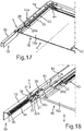
- eine perspektivische Darstellung der Tür des Hausgeräts gemäß
Fig. 1 mit Blick auf die Innenseite; - Fig. 18
- eine vergrößerte Darstellung eines Teilausschnitts der Tür gemäß
Fig. 17 ; und - Fig. 19
- eine Längsschnittdarstellung der Tür mit einem Scharnier im vollständig geöffneten Zustand der Tür.
- Fig. 1
- a perspective view of an embodiment of a domestic appliance according to the invention;
- Fig. 2
- a perspective sectional view through an embodiment of a hinge according to the invention in a first position;
- Fig. 3
- a perspective sectional view of the hinge according to
Fig. 2 in a second position; - Fig. 4
- a perspective sectional view of the hinge according to
Fig. 2 andFig. 3 in a third position; - Fig. 5
- a further partially sectioned view of the hinge in the position according to
Fig. 2 ; - Fig. 6
- a further partial sectional view of the hinge in a position according to
Fig. 3 ; - Fig. 7
- a further partial sectional view of the hinge in a position according to
Fig. 4 ; - Fig. 8
- a further illustration of the hinge in a sectional view with additional additional components in the position according to
Fig. 2 andFig. 5 ; - Fig. 9
- a representation of the hinge according to
Fig. 8 in a position according to the illustrations inFig. 3 andFig. 6 ; - Fig. 10
- a representation of the hinge according to
FIGS. 8 and 9 in a position according toFig. 4 andFig. 7 ; - Fig. 11
- a side view of the hinge according to
Fig. 8 ; - Fig. 12
- a side view of the hinge according to
Fig. 10 with additional additional components; - Fig. 13
- a side view of the hinge according to
Fig. 9 with additional additional components; - Fig. 14
- a perspective sectional view of the hinge as shown in FIG
Fig. 13 ; - Fig. 15
- a perspective sectional view of the hinge according to
Fig. 11 ; - Fig. 16
- a perspective sectional view of the hinge according to
Fig. 12 ; - Fig. 17
- a perspective view of the door of the household appliance according to
Fig. 1 facing the inside; - Fig. 18
- an enlarged view of a partial section of the door according to
Fig. 17 ; and - Fig. 19
- a longitudinal sectional view of the door with a hinge in the fully open state of the door.
In den Figuren werden gleiche oder funktionsgleiche Elemente mit den gleichen Bezugszeichen versehen.In the figures, identical or functionally identical elements are provided with the same reference numerals.
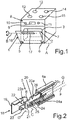
In
Das Hausgerät, nachfolgend als Backofen 1 bezeichnet, umfasst einen Garraum 2, der durch eine Muffel 3 bzw. deren Wände begrenzt ist. Die Muffel 3 weist frontseitig eine Beschickungsöffnung auf, die durch eine Tür 4 verschließbar ist. Die Tür 4 ist im Ausführungsbeispiel eine unten angeschlagene Tür, welche um eine horizontal orientierte Achse A verschwenkbar ist. Die Tür 4 ist über zwei Scharniere 5 und 6 an einem Hausgerätegehäuse 7 befestigt und relativ dazu verschwenkbar.The domestic appliance, hereinafter referred to as
Der Backofen 1 umfasst darüber hinaus eine Bedienvorrichtung 8, welche eine Anzeigeeinheit 9 und Bedienelemente 10 und 11 aufweist. Sowohl positionell als auch im Hinblick auf die Anzahl sind die Anzeigeeinheit 9 und die Bedienelemente 10 und 11 lediglich beispielhaft zu verstehen. Entsprechendes gilt auch für Kochzonen 12, 13, 14 und 15, welche der Backofen 1 umfasst.The
An der Tür 4, die eine Frontscheibe 16 aufweist, ist ein horizontal orientierter Griff 17 angeordnet, der um eine horizontal orientierte Achse B relativ zur Frontscheibe 16 verschwenkbar ist. Der Griff 17 kann dabei abhängig von der Bewegung der Tür 4 verschwenkt werden. Er ist mittels spezifischer und im Weiteren näher erläuterter Vorrichtungen mit den Scharnieren 5 und/oder 6 gekoppelt. Ist die Tür 4 im vollständig geschlossenen Zustand und steht sie somit vertikal, so ist der Griff 17 in einer ersten Grundstellung, bei der er quasi senkrecht nach vorne steht. Dies betrifft insbesondere die nicht näher gekennzeichneten und dargestellten Griffböcke, über welche eine Griffstange des Griffs 17 an der Frontscheibe 16 angeordnet ist.On the
Wird die Tür 4 geöffnet und in Richtung ihrer vollständig geöffneten zweiten Endstellung bewegt, so wird automatisch der Griff 17 um die Achse B verschwenkt. Die Griffstange des Griffs 17 ist somit immer quasi dem Nutzer zugewandt, sodass dieser sie einfach greifen kann. Im vollständig geöffneten Zustand der Tür 4, in dem sie mit ihrer Frontscheibe 16 waagerecht orientiert ist, zeigt somit die Griffstange 17 nicht in Richtung zum Boden, sondern ist so verschwenkt, dass sie auch wiederum nach vorne zeigt und von einem Nutzer auch bei vollständig geöffneter Tür 4 gegriffen werden kann.If the
Im Ausführungsbeispiel ist insbesondere vorgesehen, dass die Scharniere 5 und 6 jeweils ein Scharnierschwert und einen damit verbundenen Scharnier-Grundkörper aufweisen. Die Scharnierschwerter der Scharniere 5 und 6 sind mit der Tür 4 verbunden, wohingegen sich die Scharnier-Grundkörper im Hausgerätegehäuse 7 befinden.In the exemplary embodiment, it is provided in particular that the
Nachfolgend werden Ausführungsbeispiele für die Scharniere 5 und 6 näher erläutert. Da die beiden Scharniere 5 und 6 analog aufgebaut sind, wird die nachfolgende Beschreibung anhand des Scharniers 5 durchgeführt.Hereinafter, exemplary embodiments of the
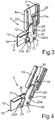
In
Wie zu erkennen ist, ist das Scharnierschwert 20 mit einem ersten plattenartigen Teil 20a ausgebildet. Parallel und beabstandet dazu ist ein gleich ausgebildetes zweites plattenartiges Teil 20b (
An dieser Stelle sei erwähnt, dass die Tür 4 zumindest die Frontscheibe 16 aufweist. Vorzugsweise umfasst die Tür 4 jedoch zumindest eine weitere Türinnenscheibe, die beabstandet zur Frontscheibe 16 angeordnet ist. Darüber hinaus können auch noch weitere Zwischenscheiben vorhanden sein. Das Türprofil 4a ist an der Innenseite der dem Garraum 2 nächstgelegenen und zugewandten Türscheibe angeordnet.At this point, it should be mentioned that the
Das Scharnier 5 umfasst darüber hinaus ein als separates Bauteil vorgesehenes Übertragungselement 22. Dieses Übertragungselement 22 umfasst einen ersten plattenartigen Bügel 22a und einen dazu beabstandet angeordneten und sich parallel erstreckenden zweiten plattenartigen Bügel 22b (
Die beiden Bügel 22a und 22b des Übertragungselements 20 sind mit einem Bolzen 23 verbunden. Mittels dieses Bolzens 23 ist auch eine direkte Verbindung des Übertragungselements 22 mit dem Gehäuse 19 des Scharnier-Grundkörpers 18 gegeben. Das als Doppelbügel ausgebildete Übertragungselement 22 ist dadurch um die Achse D des Bolzens 23 relativ drehbar zum Gehäuse 19 angeordnet.The two
Das Übertragungselement 22 weist keine direkte Verbindung mit dem Scharnierschwert 20 auf.The
Das Scharnier 5 umfasst darüber hinaus auch noch einen als separates Bauteil ausgebildeten Betätigungsgeber 24. Dieser ist einstückig ausgebildet und, wie in der Darstellung gemäß
Eine Längsachse F des Betätigungselements 24 erstreckt sich parallel zu einer Längsachse G des Scharnierschwerts 20.A longitudinal axis F of the
Darüber hinaus ist vorgesehen, dass der Betätigungsgeber 24 sich mit seinem vorderen Ende 24a über die vordere Seite 20c des Scharnierschwerts 20 hinaus erstreckt.In addition, it is provided that the
In
In dieser Anordnung ist insbesondere vorgesehen, dass Querschnittmittelpunkte der Bolzen 21, 23 und 25 auf einer Geraden liegen, die sich dann parallel zu den Längsachsen F und G erstreckt.In this arrangement it is provided in particular that cross-section centers of the
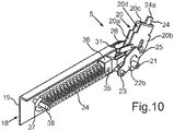
In
In der Darstellung gemäß
Wie in dieser Ansicht gemäß
Wie darüber hinaus auch zu erkennen ist, ist ein vorderes Ende 24a des Betätigungsgebers 24 in Kontakt mit einem weiteren Bolzen 29, der in einem Langloch 30 des Türprofils 4a geführt ist. Der Bolzen 29 ist einer Koppeleinheit zugehörig, mittels welcher die Bewegung des Türgriffs 17 abhängig von einer Bewegung des Scharniers 5 und/oder des Scharniers 6 bewirkbar ist. Mittels des Scharniers 5 und insbesondere des Betätigungsgebers 24 kann somit abhängig von der Relativbewegung zwischen dem Scharnierschwert 20 und dem Scharnier-Grundkörper 18 eine scharnierexterne Komponente, nämlich der Türgriff 17, automatisch betätigt werden.As can also be seen, a
Bei dieser ersten Endstellung des Scharniers 5 gemäß der Darstellung in
In
Durch das Halteelement 26 wird in der Darstellung gemäß
In
Darüber hinaus ist auch zu erkennen, dass sich das Scharnierschwert 20 und der Betätigungsgeber 24 in das Innere eines Hohlteils 4b des Türprofils 4a erstrecken, wobei dieses Hohlteil 4b als Schacht ausgebildet ist, in dem der Bolzen 29 gesichert über Splinte 32 geführt ist. Die Splinte 32 sichern darüber hinaus auch ein Seil 33, welches einer Seilzugvorrichtung zugeordnet ist. Die Seilzugvorrichtung ist mit dem Türgriff 17 verbunden, sodass abhängig von der Bewegung des Bolzens 29, initiiert durch den Betätigungsgeber 24, die Seilzugvorrichtung betätigt wird und dadurch dann der Türgriff 17 betätigt wird.In addition, it can also be seen that the
In
Wie aus den Darstellungen in
Demgegenüber ist auch zwischen den beiden beabstandet zueinander angeordneten plattenartigen Teilen 20a und 20b des Scharnierschwerts 20 ein Freiraum 20d ausgebildet, in welchen sich der Betätigungsgeber 24 erstreckt. Die Komponenten Übertragungselement 22, Scharnierschwert 20 und Betätigungsgeber 24 sind somit ineinandergeschachtelt angeordnet, sodass ein äußerst kompaktes und im Hinblick auf die multiple relative Bewegbarkeit der Bauteile zueinander robustes und hochflexibles System konzipiert ist.In contrast, between the two spaced-apart plate-
In
Es kann auch vorgesehen sein, dass zusätzlich zu der Zugfeder 34 auch ein nicht dargestellter Dämpfer in dem Gehäuse 19 angeordnet ist, mittels welchem die Bewegung der Tür 4 gedämpft werden kann. Insbesondere kann hier der Bewegungsweg kurz vor dem Erreichen der geschlossenen Endstellung der Tür 4 gedämpft werden, sodass ein harter Anschlag an dem Hausgerätegehäuse 7 verhindert wird.It can also be provided that in addition to the
In
In
Der zurückgeklappte Zustand des Halteelements 26 ist zu erkennen, welches an dem Anschlag 31 anliegt.The folded-back state of the holding
In
Die Ausgestaltung des Schlittens 40 mit der Feder 39 kann zusätzlich oder anstatt der Ausgestaltung mit dem Bolzen 29 vorgesehen sein. In
In
Mittels des Schlittens 40 wird die Bewegung auf die bereits angesprochene Seilzugvorrichtung mit dem Seil 33 übertragen und dann diese Bewegung auf den Türgriff 17 übertragen.By means of the
In
Es kann vorgesehen sein, dass das vordere Ende 24a des Betätigungsgebers 24 an der Rückseite des Schlittens 40 anliegt und diesen entsprechend betätigt bzw. verschiebt. Es kann jedoch auch vorgesehen sein, dass anstatt dieser indirekten Kopplung mit dem Bolzen 29 eine direkte Kopplung vorgesehen ist, wie dies beispielsweise in den
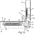
In
In
In
In der Darstellung gemäß
In
In
- 11
- Hausgeräthousehold appliance
- 22
- Garraumoven
- 33
- Muffelmuffle
- 44
- Türdoor
- 4a4a
- Türprofildoor profile
- 4b4b
- Hohlteilhollow part
- 5, 65, 6
- Scharnierehinges
- 77
- HausgerätegehäuseHome appliance housing
- 88th
- Bedienvorrichtungoperating device
- 99
- Anzeigeeinheitdisplay unit
- 10, 1110, 11
- Bedienelementecontrols
- 12, 13, 14, 1512, 13, 14, 15
- Kochzonencooking zones
- 1616
- Frontscheibewindscreen
- 16a16a
- Innenseiteinside
- 1717
- GriffHandle
- 1818
- Scharnier-GrundkörperHinge base body
- 1919
- Gehäusecasing
- 2020
- Scharnierschwerthinge sword
- 20a, 20b20a, 20b
- plattenartige Teileplate-like parts
- 20c20c
- vordere Seitefront side
- 20d20d
- Freiraumfree space
- 2121
- Bolzenbolt
- 2222
- Übertragungselementtransmission element
- 22a, 22b22a, 22b
- plattenartige Bügelplate-like hanger
- 22c22c
- Ausbuchtungenbulges
- 22d22d
- Freiraumfree space
- 2323
- Bolzenbolt
- 2424
- Betätigungsgeberoperation timer
- 24a24a
- vorderes Endefront end
- 2525
- Verbindungsbolzenconnecting bolts
- 2626
- Halteelementretaining element
- 27, 28, 3027, 28, 30
- Langlöcherslots
- 2929
- Bolzenbolt
- 29a29a
- Seilaufnahmecable receptacle
- 3131
- Anschlagattack
- 3232
- Splintecotter pins
- 3333
- Seilrope
- 3434
- Zugfedermainspring
- 3535
- vorderes Endefront end
- 3636
- Koppelelementcoupling element
- 3737
- hinteres Enderear end
- 3838
- Ankerelementanchor member
- 3939
- Federfeather
- 4040
- Schlittencarriage
- 4141
- Bolzenbolt
- 42a, 42b42a, 42b
- Anordnungenarrangements
- 4343
- Seilzugvorrichtungcable device
- 4444
- Umlenkmechanikdiverting mechanism
- 4545
- Anbindungconnection
- 4646
- Federfeather
- AA
- Achseaxis
- BB
- Achseaxis
- CC
- Achseaxis
- DD
- Achseaxis
- E, F, G, HE, F, G, H
- Längsachsenlongitudinal axes
- P1P1
- Pfeilarrow
- P2P2
- Pfeilarrow
Claims (17)
- Hinge (5, 6) with a functional unit (17) for a door (4) of a household appliance (1), with a hinge base body (18) and a hinge blade (20) that is connected thereto and is pivotable relative thereto, wherein installation of the hinge (5, 6) is possible whereby the hinge blade (20) is attached to the door, wherein a transmission element (22) is rotatably mounted on the hinge base body (18) and is coupled to an actuating sensor (24) of the hinge (5, 6) such that said actuating sensor (24) performs a movement relative to the hinge blade (20) as a function of the relative movement between the hinge blade (20) and the hinge base body (18), and wherein the transmission element (22) and the actuating sensor (24) are connected to each other rotatably relative to one another, characterised in that the hinge blade (20) has a guide (27, 28) in which the actuating sensor (24) is guided to perform its movement relative to the hinge blade (20), wherein the actuating sensor (24) is designed to actuate the door-side functional unit (17) as a function of its movement and the functional unit is a door handle (17) that can move relative to the door (4).
- Hinge (5, 6) according to claim 1, characterised in that the actuating sensor (24) is arranged without a direct connection to the hinge base body (18).
- Hinge (5, 6) according to one of the preceding claims, characterised in that the guide is a slot (27, 28).
- Hinge (5, 6) according to one of the preceding claims, characterised in that the transmission element (22) is a double bracket which has two plate-like brackets (22a, 22b) spaced apart from one another, in particular has two brackets (22a, 22b) which are connected to a bolt (23), about which the rotation of the transmission element (22) relative to the hinge base body (18) can be performed.
- Hinge (5, 6) according to claim 4, characterised in that the actuating sensor (24) extends into a free space (22d) between the brackets (22a, 22b) arranged parallel to one another.
- Hinge (5, 6) according to one of the preceding claims, characterised in that the hinge blade (20) has two plate-like parts (20a, 20b) which are arranged in parallel and spaced apart from one another, the actuating sensor (24) being arranged in particular in a free space (20d) between the parts (20a, 20b).
- Hinge (5, 6) according to one of the preceding claims, characterised in that the actuating sensor (24) is a plate-like strip.
- Hinge (5, 6) according to one of the preceding claims, characterised in that a retaining element (26) is arranged on the hinge blade (20) and is movable relative to the hinge blade (20) and in a retaining position is designed to abut the hinge base body (18) in an intermediate position which is different from the two end positions between the hinge blade (20) and the hinge base body (18), and the intermediate position is automatically held in the retaining position of the retaining element (26).
- Hinge (5, 6) according to one of the preceding claims, characterised in that the hinge base body (18) has a housing (19) in which is arranged a tension spring (34) connected to the hinge blade (20).
- Hinge (5, 6) according to one of the preceding claims, characterised in that the hinge base body (18) has a damper, with which the movement of the door (4) can, at least in sections, be damped over the entire movement path.
- Door (4) for a household appliance (1), which has at least one hinge with a hinge blade and a hinge base body, wherein the hinge blade is arranged on the door (4), characterised in that the hinge (5, 6) is designed according to one of claims 1 to 10.
- Door (4) according to claim 11, characterised in that the door handle (17) designed as a functional unit is arranged on an outer side of the door (4) and is pivotable relative to the door (4) as a function of the movement of the door (4).
- Door (4) according to claim 11 or 12, characterised in that a coupling unit (29, 39, 40, 43, 44) is arranged in the door (4) and is connected to the actuating sensor (24) of the hinge (5, 6) and to the door handle (17) and transmits the movement of the actuating sensor (24) to the door handle (17).
- Door (4) according to claim 13, characterised in that the coupling unit has a carriage (40) which is biased by a spring (39) in its position and is coupled to the actuating sensor (24).
- Door (4) according to claim 14, characterised in that the carriage (40) is connected to a cable pulling device (43) which is connected to the door handle (17).
- Household appliance (1) having a hinge (5, 6) according to one of claims 1 to 10 and/or a door (4) according to one of claims 11 to 15.
- Method for actuating a door handle (17) on a door (4) of a household appliance (1), in which the door (4) arranged on a household appliance (7) is pivoted via at least one hinge (5, 6) according to one of claims 1-10, wherein a hinge blade (20) of the hinge (5, 6) is connected to the door (4) and a hinge base body (18) is connected to the household appliance housing (7), and a transmission element (22) is rotatably mounted on the hinge base body (18) and is coupled to the actuation sensor (24) such that said actuation sensor (24) performs a movement relative to the hinge blade (20) as a function of the relative movement between the hinge blade (20) and the hinge base body (18), wherein the transmission element (22) and the actuating sensor (24) are connected to each other rotatably relative to one another, characterised in that as a function of the relative movement of the actuation sensor (24) a movement of the door handle (17) is initiated, in which the actuating sensor (24) is guided to perform its movement relative to the hinge blade (20) in a guide (27, 28) which comprises the hinge blade (20).
Priority Applications (1)
| Application Number | Priority Date | Filing Date | Title |
|---|---|---|---|
| PL12172961T PL2540940T3 (en) | 2011-07-01 | 2012-06-21 | Hinge for the door of a domestic appliance, door with such a hinge and domestic appliance with such a hinge and method for actuating a door handle of a door |
Applications Claiming Priority (1)
| Application Number | Priority Date | Filing Date | Title |
|---|---|---|---|
| DE102011078535A DE102011078535A1 (en) | 2011-07-01 | 2011-07-01 | Hinge for a door of a domestic appliance, door with such a hinge and household appliance with a corresponding hinge and method for actuating a door handle of a door |
Publications (3)
| Publication Number | Publication Date |
|---|---|
| EP2540940A2 EP2540940A2 (en) | 2013-01-02 |
| EP2540940A3 EP2540940A3 (en) | 2017-12-27 |
| EP2540940B1 true EP2540940B1 (en) | 2019-03-13 |
Family
ID=46319041
Family Applications (1)
| Application Number | Title | Priority Date | Filing Date |
|---|---|---|---|
| EP12172961.0A Active EP2540940B1 (en) | 2011-07-01 | 2012-06-21 | Hinge for the door of a domestic appliance, door with such a hinge and domestic appliance with such a hinge and method for actuating a door handle of a door |
Country Status (5)
| Country | Link |
|---|---|
| EP (1) | EP2540940B1 (en) |
| DE (1) | DE102011078535A1 (en) |
| ES (1) | ES2720849T3 (en) |
| PL (1) | PL2540940T3 (en) |
| TR (1) | TR201904474T4 (en) |
Families Citing this family (6)
| Publication number | Priority date | Publication date | Assignee | Title |
|---|---|---|---|---|
| DE102012222160A1 (en) * | 2012-12-04 | 2014-06-05 | BSH Bosch und Siemens Hausgeräte GmbH | Device for a household appliance with a hinge and a coupling device and household appliance with such a device |
| DE102015226009A1 (en) | 2015-12-18 | 2017-06-22 | BSH Hausgeräte GmbH | Cooking appliance with a door opening device for automatically bringing a door into an intermediate position and method for opening a door of a cooking appliance |
| DE102017207980A1 (en) * | 2017-05-11 | 2018-11-15 | BSH Hausgeräte GmbH | Cooking device with a cable device for automatically pivoting a door |
| DE102017213095A1 (en) * | 2017-07-28 | 2019-01-31 | BSH Hausgeräte GmbH | Cooking appliance with retractable door, which has a specific retaining spring for a bearing bush |
| DE102018214393A1 (en) * | 2018-08-27 | 2020-02-27 | BSH Hausgeräte GmbH | Household microwave |
| CN109386196A (en) * | 2018-12-21 | 2019-02-26 | 合肥口福科技有限公司 | Door is pulled back hinge means |
Family Cites Families (5)
| Publication number | Priority date | Publication date | Assignee | Title |
|---|---|---|---|---|
| IT1235584B (en) * | 1989-09-06 | 1992-09-11 | C M I Cerniere Meccaniche Indu | HINGE FOR OPENING AND SEMI-AUTOMATIC CLOSING OF DOORS PARTICULARLY SUITABLE FOR FRONT DOORS WITH HORIZONTAL AXIS OF DISHWASHER |
| DE19923994A1 (en) | 1999-05-26 | 2000-11-30 | Bsh Bosch Siemens Hausgeraete | Household appliance hinge device |
| DE10208494B4 (en) * | 2002-02-27 | 2008-04-17 | BSH Bosch und Siemens Hausgeräte GmbH | Home appliance door and home appliance |
| ITPD20060034A1 (en) * | 2006-02-02 | 2007-08-03 | Zanovello Srl | HINGE FOR OVEN OR SIMILAR DOORS |
| DE102007041909A1 (en) * | 2007-09-04 | 2009-03-05 | BSH Bosch und Siemens Hausgeräte GmbH | Hinge housing for a household appliance door |
-
2011
- 2011-07-01 DE DE102011078535A patent/DE102011078535A1/en not_active Withdrawn
-
2012
- 2012-06-21 TR TR2019/04474T patent/TR201904474T4/en unknown
- 2012-06-21 EP EP12172961.0A patent/EP2540940B1/en active Active
- 2012-06-21 ES ES12172961T patent/ES2720849T3/en active Active
- 2012-06-21 PL PL12172961T patent/PL2540940T3/en unknown
Non-Patent Citations (1)
| Title |
|---|
| None * |
Also Published As
| Publication number | Publication date |
|---|---|
| ES2720849T3 (en) | 2019-07-25 |
| DE102011078535A1 (en) | 2013-01-03 |
| PL2540940T3 (en) | 2019-09-30 |
| EP2540940A2 (en) | 2013-01-02 |
| EP2540940A3 (en) | 2017-12-27 |
| TR201904474T4 (en) | 2019-04-22 |
Similar Documents
| Publication | Publication Date | Title |
|---|---|---|
| EP2540940B1 (en) | Hinge for the door of a domestic appliance, door with such a hinge and domestic appliance with such a hinge and method for actuating a door handle of a door | |
| EP2191088B2 (en) | Door hinge for a household appliance | |
| EP3622223B1 (en) | Cooking appliance having a cable pull device for automatically pivoting a door | |
| EP2250929B1 (en) | Cupboard section with extricable section | |
| EP2362050A2 (en) | Hinge device, domestic appliance with a door and method for retrofitting a damper | |
| DE102019213486A1 (en) | Cooking device with a specific door opening device for automatically pivoting a retractable door of the cooking device, as well as a method | |
| WO2012038339A1 (en) | Automatic retraction apparatus for a movable furniture part | |
| EP2992156B1 (en) | Guiding assembly of a sliding door, a sliding door and a piece of furniture | |
| EP3658824B1 (en) | Cooking appliance comprising a lowerable door, which has a specific retaining spring for a bearing bush | |
| EP2581666B1 (en) | Door for a domestic appliance, domestic appliance with a door and method for moving a handle of a door of a domestic appliance | |
| DE102016215651A1 (en) | Retractable door with a swiveling plate-like handle and household appliance | |
| DE102009002419B4 (en) | Door with at least one actuating element and at least one latch | |
| EP2189726A2 (en) | Retractable grip for a door of a household device and door of a household device with such a grip | |
| EP2741015B1 (en) | Door for a domestic appliance with a plate-like handle part and a handle opener, domestic appliance with such a door and method for opening a door of a domestic appliance | |
| EP2884188B1 (en) | Household device with a door that is stowable into a storage area and with slidable rotational axis of a bearing unit and method for opening and closing such a door | |
| DE10009633A1 (en) | Door catch system has the door handle and door lock offset and linked by a transmission | |
| WO2016020344A1 (en) | Door for a household appliance, and household appliance having a door | |
| EP2930436B1 (en) | Household appliance with a stowable door and method for opening and closing a door of a household appliance | |
| DE102009058678B4 (en) | Adjustment device for adjusting, in particular for translational displacement, at least one furniture part | |
| EP2884189B1 (en) | Household appliance with a door that can be retracted into a stowing area and method for opening and closing a door of a domestic appliance | |
| EP2740871A2 (en) | Device for a domestic appliance with a hinge and a coupling device and domestic appliance with such a device | |
| DE102022203509A1 (en) | Household appliance with a specific coupling-slide system for a retractable door, and method | |
| DE102010023526B4 (en) | Device housing with a door | |
| WO2023194082A1 (en) | Domestic appliance with specific driver system for actuating the door, and method | |
| DE202008010686U1 (en) | Window or door with an opening limiter |
Legal Events
| Date | Code | Title | Description |
|---|---|---|---|
| PUAI | Public reference made under article 153(3) epc to a published international application that has entered the european phase |
Free format text: ORIGINAL CODE: 0009012 |
|
| AK | Designated contracting states |
Kind code of ref document: A2 Designated state(s): AL AT BE BG CH CY CZ DE DK EE ES FI FR GB GR HR HU IE IS IT LI LT LU LV MC MK MT NL NO PL PT RO RS SE SI SK SM TR |
|
| AX | Request for extension of the european patent |
Extension state: BA ME |
|
| RAP1 | Party data changed (applicant data changed or rights of an application transferred) |
Owner name: BSH HAUSGERAETE GMBH |
|
| PUAL | Search report despatched |
Free format text: ORIGINAL CODE: 0009013 |
|
| AK | Designated contracting states |
Kind code of ref document: A3 Designated state(s): AL AT BE BG CH CY CZ DE DK EE ES FI FR GB GR HR HU IE IS IT LI LT LU LV MC MK MT NL NO PL PT RO RS SE SI SK SM TR |
|
| AX | Request for extension of the european patent |
Extension state: BA ME |
|
| RIC1 | Information provided on ipc code assigned before grant |
Ipc: E05F 5/00 20170101ALN20171123BHEP Ipc: E05F 1/12 20060101ALI20171123BHEP Ipc: E05D 3/02 20060101AFI20171123BHEP Ipc: E05D 3/18 20060101ALN20171123BHEP |
|
| STAA | Information on the status of an ep patent application or granted ep patent |
Free format text: STATUS: REQUEST FOR EXAMINATION WAS MADE |
|
| 17P | Request for examination filed |
Effective date: 20180627 |
|
| RBV | Designated contracting states (corrected) |
Designated state(s): AL AT BE BG CH CY CZ DE DK EE ES FI FR GB GR HR HU IE IS IT LI LT LU LV MC MK MT NL NO PL PT RO RS SE SI SK SM TR |
|
| RIC1 | Information provided on ipc code assigned before grant |
Ipc: E05F 1/12 20060101ALI20180823BHEP Ipc: E05D 3/02 20060101AFI20180823BHEP Ipc: E05D 3/18 20060101ALN20180823BHEP Ipc: E05F 5/00 20060101ALN20180823BHEP |
|
| GRAJ | Information related to disapproval of communication of intention to grant by the applicant or resumption of examination proceedings by the epo deleted |
Free format text: ORIGINAL CODE: EPIDOSDIGR1 |
|
| GRAP | Despatch of communication of intention to grant a patent |
Free format text: ORIGINAL CODE: EPIDOSNIGR1 |
|
| GRAP | Despatch of communication of intention to grant a patent |
Free format text: ORIGINAL CODE: EPIDOSNIGR1 |
|
| STAA | Information on the status of an ep patent application or granted ep patent |
Free format text: STATUS: GRANT OF PATENT IS INTENDED |
|
| RIC1 | Information provided on ipc code assigned before grant |
Ipc: E05F 1/12 20060101ALI20181003BHEP Ipc: E05D 3/02 20060101AFI20181003BHEP Ipc: E05F 5/00 20060101ALN20181003BHEP Ipc: E05D 3/18 20060101ALN20181003BHEP |
|
| INTG | Intention to grant announced |
Effective date: 20181016 |
|
| GRAS | Grant fee paid |
Free format text: ORIGINAL CODE: EPIDOSNIGR3 |
|
| GRAA | (expected) grant |
Free format text: ORIGINAL CODE: 0009210 |
|
| STAA | Information on the status of an ep patent application or granted ep patent |
Free format text: STATUS: THE PATENT HAS BEEN GRANTED |
|
| AK | Designated contracting states |
Kind code of ref document: B1 Designated state(s): AL AT BE BG CH CY CZ DE DK EE ES FI FR GB GR HR HU IE IS IT LI LT LU LV MC MK MT NL NO PL PT RO RS SE SI SK SM TR |
|
| REG | Reference to a national code |
Ref country code: GB Ref legal event code: FG4D Free format text: NOT ENGLISH |
|
| REG | Reference to a national code |
Ref country code: CH Ref legal event code: EP Ref country code: AT Ref legal event code: REF Ref document number: 1107875 Country of ref document: AT Kind code of ref document: T Effective date: 20190315 |
|
| REG | Reference to a national code |
Ref country code: IE Ref legal event code: FG4D Free format text: LANGUAGE OF EP DOCUMENT: GERMAN |
|
| REG | Reference to a national code |
Ref country code: DE Ref legal event code: R096 Ref document number: 502012014424 Country of ref document: DE |
|
| REG | Reference to a national code |
Ref country code: NL Ref legal event code: MP Effective date: 20190313 |
|
| REG | Reference to a national code |
Ref country code: ES Ref legal event code: FG2A Ref document number: 2720849 Country of ref document: ES Kind code of ref document: T3 Effective date: 20190725 Ref country code: LT Ref legal event code: MG4D |
|
| PG25 | Lapsed in a contracting state [announced via postgrant information from national office to epo] |
Ref country code: FI Free format text: LAPSE BECAUSE OF FAILURE TO SUBMIT A TRANSLATION OF THE DESCRIPTION OR TO PAY THE FEE WITHIN THE PRESCRIBED TIME-LIMIT Effective date: 20190313 Ref country code: NO Free format text: LAPSE BECAUSE OF FAILURE TO SUBMIT A TRANSLATION OF THE DESCRIPTION OR TO PAY THE FEE WITHIN THE PRESCRIBED TIME-LIMIT Effective date: 20190613 Ref country code: SE Free format text: LAPSE BECAUSE OF FAILURE TO SUBMIT A TRANSLATION OF THE DESCRIPTION OR TO PAY THE FEE WITHIN THE PRESCRIBED TIME-LIMIT Effective date: 20190313 Ref country code: LT Free format text: LAPSE BECAUSE OF FAILURE TO SUBMIT A TRANSLATION OF THE DESCRIPTION OR TO PAY THE FEE WITHIN THE PRESCRIBED TIME-LIMIT Effective date: 20190313 |
|
| PG25 | Lapsed in a contracting state [announced via postgrant information from national office to epo] |
Ref country code: HR Free format text: LAPSE BECAUSE OF FAILURE TO SUBMIT A TRANSLATION OF THE DESCRIPTION OR TO PAY THE FEE WITHIN THE PRESCRIBED TIME-LIMIT Effective date: 20190313 Ref country code: GR Free format text: LAPSE BECAUSE OF FAILURE TO SUBMIT A TRANSLATION OF THE DESCRIPTION OR TO PAY THE FEE WITHIN THE PRESCRIBED TIME-LIMIT Effective date: 20190614 Ref country code: NL Free format text: LAPSE BECAUSE OF FAILURE TO SUBMIT A TRANSLATION OF THE DESCRIPTION OR TO PAY THE FEE WITHIN THE PRESCRIBED TIME-LIMIT Effective date: 20190313 Ref country code: LV Free format text: LAPSE BECAUSE OF FAILURE TO SUBMIT A TRANSLATION OF THE DESCRIPTION OR TO PAY THE FEE WITHIN THE PRESCRIBED TIME-LIMIT Effective date: 20190313 Ref country code: BG Free format text: LAPSE BECAUSE OF FAILURE TO SUBMIT A TRANSLATION OF THE DESCRIPTION OR TO PAY THE FEE WITHIN THE PRESCRIBED TIME-LIMIT Effective date: 20190613 Ref country code: RS Free format text: LAPSE BECAUSE OF FAILURE TO SUBMIT A TRANSLATION OF THE DESCRIPTION OR TO PAY THE FEE WITHIN THE PRESCRIBED TIME-LIMIT Effective date: 20190313 |
|
| PG25 | Lapsed in a contracting state [announced via postgrant information from national office to epo] |
Ref country code: SK Free format text: LAPSE BECAUSE OF FAILURE TO SUBMIT A TRANSLATION OF THE DESCRIPTION OR TO PAY THE FEE WITHIN THE PRESCRIBED TIME-LIMIT Effective date: 20190313 Ref country code: RO Free format text: LAPSE BECAUSE OF FAILURE TO SUBMIT A TRANSLATION OF THE DESCRIPTION OR TO PAY THE FEE WITHIN THE PRESCRIBED TIME-LIMIT Effective date: 20190313 Ref country code: CZ Free format text: LAPSE BECAUSE OF FAILURE TO SUBMIT A TRANSLATION OF THE DESCRIPTION OR TO PAY THE FEE WITHIN THE PRESCRIBED TIME-LIMIT Effective date: 20190313 Ref country code: IT Free format text: LAPSE BECAUSE OF FAILURE TO SUBMIT A TRANSLATION OF THE DESCRIPTION OR TO PAY THE FEE WITHIN THE PRESCRIBED TIME-LIMIT Effective date: 20190313 Ref country code: EE Free format text: LAPSE BECAUSE OF FAILURE TO SUBMIT A TRANSLATION OF THE DESCRIPTION OR TO PAY THE FEE WITHIN THE PRESCRIBED TIME-LIMIT Effective date: 20190313 Ref country code: PT Free format text: LAPSE BECAUSE OF FAILURE TO SUBMIT A TRANSLATION OF THE DESCRIPTION OR TO PAY THE FEE WITHIN THE PRESCRIBED TIME-LIMIT Effective date: 20190713 Ref country code: AL Free format text: LAPSE BECAUSE OF FAILURE TO SUBMIT A TRANSLATION OF THE DESCRIPTION OR TO PAY THE FEE WITHIN THE PRESCRIBED TIME-LIMIT Effective date: 20190313 |
|
| PG25 | Lapsed in a contracting state [announced via postgrant information from national office to epo] |
Ref country code: SM Free format text: LAPSE BECAUSE OF FAILURE TO SUBMIT A TRANSLATION OF THE DESCRIPTION OR TO PAY THE FEE WITHIN THE PRESCRIBED TIME-LIMIT Effective date: 20190313 |
|
| REG | Reference to a national code |
Ref country code: DE Ref legal event code: R097 Ref document number: 502012014424 Country of ref document: DE |
|
| PG25 | Lapsed in a contracting state [announced via postgrant information from national office to epo] |
Ref country code: IS Free format text: LAPSE BECAUSE OF FAILURE TO SUBMIT A TRANSLATION OF THE DESCRIPTION OR TO PAY THE FEE WITHIN THE PRESCRIBED TIME-LIMIT Effective date: 20190713 |
|
| PLBE | No opposition filed within time limit |
Free format text: ORIGINAL CODE: 0009261 |
|
| STAA | Information on the status of an ep patent application or granted ep patent |
Free format text: STATUS: NO OPPOSITION FILED WITHIN TIME LIMIT |
|
| PG25 | Lapsed in a contracting state [announced via postgrant information from national office to epo] |
Ref country code: DK Free format text: LAPSE BECAUSE OF FAILURE TO SUBMIT A TRANSLATION OF THE DESCRIPTION OR TO PAY THE FEE WITHIN THE PRESCRIBED TIME-LIMIT Effective date: 20190313 Ref country code: MC Free format text: LAPSE BECAUSE OF FAILURE TO SUBMIT A TRANSLATION OF THE DESCRIPTION OR TO PAY THE FEE WITHIN THE PRESCRIBED TIME-LIMIT Effective date: 20190313 |
|
| REG | Reference to a national code |
Ref country code: CH Ref legal event code: PL |
|
| 26N | No opposition filed |
Effective date: 20191216 |
|
| PG25 | Lapsed in a contracting state [announced via postgrant information from national office to epo] |
Ref country code: SI Free format text: LAPSE BECAUSE OF FAILURE TO SUBMIT A TRANSLATION OF THE DESCRIPTION OR TO PAY THE FEE WITHIN THE PRESCRIBED TIME-LIMIT Effective date: 20190313 |
|
| REG | Reference to a national code |
Ref country code: BE Ref legal event code: MM Effective date: 20190630 |
|
| PG25 | Lapsed in a contracting state [announced via postgrant information from national office to epo] |
Ref country code: IE Free format text: LAPSE BECAUSE OF NON-PAYMENT OF DUE FEES Effective date: 20190621 |
|
| PG25 | Lapsed in a contracting state [announced via postgrant information from national office to epo] |
Ref country code: BE Free format text: LAPSE BECAUSE OF NON-PAYMENT OF DUE FEES Effective date: 20190630 Ref country code: LI Free format text: LAPSE BECAUSE OF NON-PAYMENT OF DUE FEES Effective date: 20190630 Ref country code: LU Free format text: LAPSE BECAUSE OF NON-PAYMENT OF DUE FEES Effective date: 20190621 Ref country code: CH Free format text: LAPSE BECAUSE OF NON-PAYMENT OF DUE FEES Effective date: 20190630 |
|
| REG | Reference to a national code |
Ref country code: AT Ref legal event code: MM01 Ref document number: 1107875 Country of ref document: AT Kind code of ref document: T Effective date: 20190621 |
|
| PG25 | Lapsed in a contracting state [announced via postgrant information from national office to epo] |
Ref country code: AT Free format text: LAPSE BECAUSE OF NON-PAYMENT OF DUE FEES Effective date: 20190621 |
|
| PG25 | Lapsed in a contracting state [announced via postgrant information from national office to epo] |
Ref country code: CY Free format text: LAPSE BECAUSE OF FAILURE TO SUBMIT A TRANSLATION OF THE DESCRIPTION OR TO PAY THE FEE WITHIN THE PRESCRIBED TIME-LIMIT Effective date: 20190313 |
|
| PG25 | Lapsed in a contracting state [announced via postgrant information from national office to epo] |
Ref country code: MT Free format text: LAPSE BECAUSE OF FAILURE TO SUBMIT A TRANSLATION OF THE DESCRIPTION OR TO PAY THE FEE WITHIN THE PRESCRIBED TIME-LIMIT Effective date: 20190313 Ref country code: HU Free format text: LAPSE BECAUSE OF FAILURE TO SUBMIT A TRANSLATION OF THE DESCRIPTION OR TO PAY THE FEE WITHIN THE PRESCRIBED TIME-LIMIT; INVALID AB INITIO Effective date: 20120621 |
|
| PG25 | Lapsed in a contracting state [announced via postgrant information from national office to epo] |
Ref country code: MK Free format text: LAPSE BECAUSE OF FAILURE TO SUBMIT A TRANSLATION OF THE DESCRIPTION OR TO PAY THE FEE WITHIN THE PRESCRIBED TIME-LIMIT Effective date: 20190313 |
|
| P01 | Opt-out of the competence of the unified patent court (upc) registered |
Effective date: 20230504 |
|
| PGFP | Annual fee paid to national office [announced via postgrant information from national office to epo] |
Ref country code: FR Payment date: 20230621 Year of fee payment: 12 Ref country code: DE Payment date: 20230630 Year of fee payment: 12 |
|
| PGFP | Annual fee paid to national office [announced via postgrant information from national office to epo] |
Ref country code: TR Payment date: 20230616 Year of fee payment: 12 Ref country code: PL Payment date: 20230616 Year of fee payment: 12 |
|
| PGFP | Annual fee paid to national office [announced via postgrant information from national office to epo] |
Ref country code: GB Payment date: 20230622 Year of fee payment: 12 Ref country code: ES Payment date: 20230719 Year of fee payment: 12 |