EP2540613A1 - Anschlussvorrichtung für eine Versorgungsleitung - Google Patents
Anschlussvorrichtung für eine Versorgungsleitung Download PDFInfo
- Publication number
- EP2540613A1 EP2540613A1 EP11005270A EP11005270A EP2540613A1 EP 2540613 A1 EP2540613 A1 EP 2540613A1 EP 11005270 A EP11005270 A EP 11005270A EP 11005270 A EP11005270 A EP 11005270A EP 2540613 A1 EP2540613 A1 EP 2540613A1
- Authority
- EP
- European Patent Office
- Prior art keywords
- connection
- connecting device
- release
- elements
- plate
- Prior art date
- Legal status (The legal status is an assumption and is not a legal conclusion. Google has not performed a legal analysis and makes no representation as to the accuracy of the status listed.)
- Granted
Links
Images



Classifications
-
- F—MECHANICAL ENGINEERING; LIGHTING; HEATING; WEAPONS; BLASTING
- F16—ENGINEERING ELEMENTS AND UNITS; GENERAL MEASURES FOR PRODUCING AND MAINTAINING EFFECTIVE FUNCTIONING OF MACHINES OR INSTALLATIONS; THERMAL INSULATION IN GENERAL
- F16L—PIPES; JOINTS OR FITTINGS FOR PIPES; SUPPORTS FOR PIPES, CABLES OR PROTECTIVE TUBING; MEANS FOR THERMAL INSULATION IN GENERAL
- F16L39/00—Joints or fittings for double-walled or multi-channel pipes or pipe assemblies
-
- F—MECHANICAL ENGINEERING; LIGHTING; HEATING; WEAPONS; BLASTING
- F16—ENGINEERING ELEMENTS AND UNITS; GENERAL MEASURES FOR PRODUCING AND MAINTAINING EFFECTIVE FUNCTIONING OF MACHINES OR INSTALLATIONS; THERMAL INSULATION IN GENERAL
- F16L—PIPES; JOINTS OR FITTINGS FOR PIPES; SUPPORTS FOR PIPES, CABLES OR PROTECTIVE TUBING; MEANS FOR THERMAL INSULATION IN GENERAL
- F16L37/00—Couplings of the quick-acting type
- F16L37/08—Couplings of the quick-acting type in which the connection between abutting or axially overlapping ends is maintained by locking members
-
- F—MECHANICAL ENGINEERING; LIGHTING; HEATING; WEAPONS; BLASTING
- F16—ENGINEERING ELEMENTS AND UNITS; GENERAL MEASURES FOR PRODUCING AND MAINTAINING EFFECTIVE FUNCTIONING OF MACHINES OR INSTALLATIONS; THERMAL INSULATION IN GENERAL
- F16L—PIPES; JOINTS OR FITTINGS FOR PIPES; SUPPORTS FOR PIPES, CABLES OR PROTECTIVE TUBING; MEANS FOR THERMAL INSULATION IN GENERAL
- F16L1/00—Laying or reclaiming pipes; Repairing or joining pipes on or under water
- F16L1/26—Repairing or joining pipes on or under water
-
- F—MECHANICAL ENGINEERING; LIGHTING; HEATING; WEAPONS; BLASTING
- F16—ENGINEERING ELEMENTS AND UNITS; GENERAL MEASURES FOR PRODUCING AND MAINTAINING EFFECTIVE FUNCTIONING OF MACHINES OR INSTALLATIONS; THERMAL INSULATION IN GENERAL
- F16L—PIPES; JOINTS OR FITTINGS FOR PIPES; SUPPORTS FOR PIPES, CABLES OR PROTECTIVE TUBING; MEANS FOR THERMAL INSULATION IN GENERAL
- F16L37/00—Couplings of the quick-acting type
- F16L37/002—Couplings of the quick-acting type which can be controlled at a distance
-
- F—MECHANICAL ENGINEERING; LIGHTING; HEATING; WEAPONS; BLASTING
- F16—ENGINEERING ELEMENTS AND UNITS; GENERAL MEASURES FOR PRODUCING AND MAINTAINING EFFECTIVE FUNCTIONING OF MACHINES OR INSTALLATIONS; THERMAL INSULATION IN GENERAL
- F16L—PIPES; JOINTS OR FITTINGS FOR PIPES; SUPPORTS FOR PIPES, CABLES OR PROTECTIVE TUBING; MEANS FOR THERMAL INSULATION IN GENERAL
- F16L39/00—Joints or fittings for double-walled or multi-channel pipes or pipe assemblies
- F16L39/06—Joints or fittings for double-walled or multi-channel pipes or pipe assemblies of the multiline swivel type, e.g. comprising a plurality of axially mounted modules
-
- H—ELECTRICITY
- H01—ELECTRIC ELEMENTS
- H01R—ELECTRICALLY-CONDUCTIVE CONNECTIONS; STRUCTURAL ASSOCIATIONS OF A PLURALITY OF MUTUALLY-INSULATED ELECTRICAL CONNECTING ELEMENTS; COUPLING DEVICES; CURRENT COLLECTORS
- H01R13/00—Details of coupling devices of the kinds covered by groups H01R12/70 or H01R24/00 - H01R33/00
- H01R13/46—Bases; Cases
- H01R13/52—Dustproof, splashproof, drip-proof, waterproof, or flameproof cases
- H01R13/523—Dustproof, splashproof, drip-proof, waterproof, or flameproof cases for use under water
Definitions
- the invention relates to a connection device for a supply line with an enveloping tube and at least two inner lines arranged therein, wherein a housing with a first connection region for the enveloping tube and a second connection region for the inner lines is provided.
- Such supply lines are used, for example, to connect underwater units with supply vessels.
- energy, data and various fluids are supplied to the underwater unit via the supply line, so that it can operate in the desired manner, for example, at the bottom of the sea or a lake.
- Such a supply line has different lines within a Hüllschlauches according to the supply to be provided.
- a generic connection device is for example from the US 5,295,848 known.
- a sleeve-shaped plug-in device is provided, through which an outer sleeve can be inserted axially into a corresponding receiving socket.
- Inside the sleeve are axial connections in Axially mounted movably to allow for connecting first, a connection of the inner leads, before the outer jacket tube can be attached.
- connection device thus takes place a connection of the inner lines at a time at which the outer sleeve tube is not mechanically attached.
- a stronger sea state for example, can be done by uncontrolled movements of the supply ship tearing of the connected inner lines when the buffer tube is not attached.
- a release of the supply line in certain emergency situations is not very fast, since first the connection of the surrounding Hüllschlauches must be solved and only then a release of the axial connectors of the inner cables is possible.
- the invention has for its object to provide a connection device for a supply line, which on the one hand, a reliable and safe connection and still allows quick release.
- the connecting device is characterized in that the first connection region has at least one retaining element which is radially or resiliently displaceable for holding or releasing the enveloping tube and the second connection region is arranged axially spaced from the first connection region and axially operable plug-in connection elements for the inner pipes.
- a first aspect of the invention is to provide a radially adjustable retaining element for connecting the Hüllschlauches.
- the buffer tube absorbs the essential mechanical forces of the supply line. While jamming could occur in the case of an axial connection with possible high mechanical transverse forces, a radially adjustable retaining element can also be easily added or reset even when high mechanical stresses are applied to the flexible hose become. This allows a fast and reliable mechanical release of the Hüllschlauches the supply line especially in emergency situations.
- a further aspect of the invention consists in that the first connection region for connecting the enveloping tube is arranged axially spaced from the second connection region for the axial plug connection elements of the inner lines. In this way it is made possible that first the outer sheath tube is connected. When this mechanically stable connection is made, in the spaced second connection region, the inner tubes projecting from the jacket tube can be securely connected or disconnected. In this way prevents violent movements of a supply ship tear off internal hydraulic lines and so uncontrolled hydraulic fluid escapes.
- sufficient space for the arrangement of the connector elements so that they can be easily and reliably operated by operators.
- a preferred embodiment of the invention is that two plate-shaped holding elements are provided, which are mounted displaceably on opposite sides of the Hüllschlauches. With such plate-shaped retaining elements, the buffer tube can be clamped reliably on the first connection region. By simply moving back the retaining elements a fast and secure release of the connection is possible even at high voltages.
- the displacement of the plate-shaped holding elements can be done by hand.
- the at least one holding element can be actuated by means of a setting cylinder.
- the adjusting cylinder is preferably a hydraulic cylinder, which is controlled via a corresponding control device.
- the plug connection elements on a connecting plate in at least one Row are arranged side by side.
- the arrangement may in particular also have two or more rows. This allows a space-saving compact arrangement, but still provides good accessibility for operators.
- the individual plug connection elements for the inner lines are always plugged by hand into corresponding counterparts on the second connection area.
- a release can be done in the same way by hand.
- a release device is provided for the common release of the inner lines of the connector elements.
- This release device for example, actively pull out the corresponding plug of the inner cables from the connector elements.
- the release movement can also consist in that the plug of the inner cables are moved in the direction of the plug-in elements, in which case disengage the plug from the connector elements and are solved.
- the release device can perform the appropriate release movement depending on the nature of the connector element.
- the release device has at least one release plate with actuating cams which partially comprise plug-in elements of the inner lines for axial actuation.
- actuating cams which partially comprise plug-in elements of the inner lines for axial actuation.
- radial projections or collars may be provided on the plug-in elements, which come into contact with the release plate for applying an axial release movement.
- the release plate may be formed approximately comb-like, wherein the comb teeth form the actuating cams.
- a release is achieved according to the invention particularly reliable, that the release device is actuated by means of a setting cylinder.
- This actuating cylinder is preferably also a hydraulic cylinder.
- a control device is provided, through which the at least one holding element for the enveloping tube and the release device for the inner tubes coordinated with each other are operable. It is preferred that the release of the inner lines takes place temporally before or at least simultaneously with the release of the Hüllschlauches. In this way it is prevented that excessive mechanical loads are transmitted to the sensitive electrical, electronic or hydraulic plug-in elements or couplings.
- the inner cables comprise power cables, data cables and / or fluid hoses.
- the fluid hoses may be hydraulic or pneumatic hoses. Also supply hoses for water, air or other liquids and gases are also possible.
- a further preferred embodiment according to the invention is that the housing has an outer plate, on which the first connection region for the enveloping tube is provided, that the outer plate has a passage opening through which the inner conduits are feasible into the housing to the second connection region, and a guide funnel is arranged between the outer plate and the second connection region, said guide funnel tapering towards the passage opening.
- the inner lines can be arranged very compact within the Hüllschlauches, which may be about a delivery hose, which is known in construction machines and in particular trench wall milling.
- the inner lines can branch out of the outer tube after emerging, so that there is sufficient space for operating on the second connection region.
- a guide funnel is provided in order to ensure a secure passage of the connector through the through hole of the connection plate in a controlled caps. This guide funnel is arranged at the passage opening and widens towards the second connection area.
- guide strips are arranged between the connection plate and a connection plate of the second connection region. These guide rails serve as well as the guide funnel a controlled discharge of the inner pipes through the passage opening at a controlled caps of the supply line.
- the connecting device 10 comprises a box-shaped housing 12 which is mounted on a base frame 14 made of steel beams.
- the base frame 14 may be fixedly connected to a supply ship.
- the connecting device 10 is used for the detachable connection of a supply line 60 with an outer sleeve 62 and inner lines 64 disposed therein, which are to be detachably connected to corresponding stationary lines 16. In this way, via the stationary lines 16 from the supply ship via the supply line 60, a connection to, for example, a submarine unit.
- connection device 10 has on its front side a first connection region 20 for the outer enveloping hose 62.
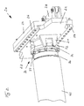
- This includes the housing 12, a front outer panel 24 on which guide rails 26 are provided for linearly guiding two opposite plate-shaped holding members 22 at the top and bottom.
- the holding elements 22 can be moved linearly via adjusting cylinder 28 between the illustrated open position and a closed position for holding the enveloping tube 62. Structure and function are described below with reference to Figures 2 and 3 explained in more detail.
- the inner conduits 64 which may be data cables, electrical cables, hydraulic fluid lines, air or other fluids, extend beyond the end of the sheath tube 62, through a passageway 30 in the outer panel 24 into the housing 12 of the interface device 10.
- the inner leads 64 which in Fig. 1 are shown partially cut, extending to a rear-side second connection portion 40, at which the stationary lines 16 open.
- plug-in elements 66 are arranged, which are formed to match corresponding plug connection elements on the second connection portion 40 for establishing a line connection.
- a release device 50 which has two pivotally arranged comb-like release plates 52 according to the illustrated embodiment. Structure and function of the release device 50 will be described below in connection with FIGS. 4 to 6 explained in more detail.
- the connecting line 60 can be easily removed from the housing 12.
- plate-shaped guide rails 34 and a guide funnel 32 are arranged in the housing 12, which tapers from the interior of the housing 12 to the through hole 30 in the outer plate 24.
- FIGS. 2 and 3 From the Figures 2 and 3 are structure and function of the first connection portion 20 for connecting the outer Hüllschlauches 62 closer removed.
- a hose connector 70 is attached at the end of Hüllschlauches 62 .
- the flexible hose portion is fixedly connected to a sleeve-shaped shaft 76, to which a centering ring 72 connects.
- On the outer side of the centering ring 72 two opposing centering pins 74 are arranged, which protrude radially.
- an end sleeve 77 of the hose connector 70 connects to the centering ring 72, wherein at the free end of the ferrule 77, an annular collar 78 projects radially outwards, as is apparent from the open position Fig. 3 results.
- the buffer tube 62 can be pushed axially up to a stop (not shown) against the first connection region 20.
- the two plate-shaped holding elements 22 are moved axially to each other.
- the holding elements 22 are linearly guided at their top and bottom in guide rails 26, which in turn are fixed to the outer plate 24 of the housing 12.
- connection device 10 a reliable, mechanically stable connection of the enveloping tube 62 to the connection device 10 is ensured by the first connection region 20.
- the configuration of the second connection region 40 will be described below in connection with FIGS FIGS. 4 to 6 explained.
- the second connection region 40 comprises a connection plate 44 which forms the rear side of the housing 12.
- the stationary lines 16 open into plug connection elements 42 which project into the interior of the housing 12.
- Plug elements 66 are formed to produce a corresponding line connection by axial insertion.
- Fig. 4 shows the second connection portion 40 in the closed position, ie with connected inner lines 64.
- the connector elements 42 are arranged in two rows one above the other on the connecting plate 44.
- two comb-like release plates 52 of a release device 50 are pivoted about their respective pivot axis 53 into their locking position, in which the release plates 52 are arranged approximately parallel to the connection plate 44.
- Fig. 4 the two release plates 52 are locked in their closed position by means of a locking bar 46.
- the locking bar 46 is mounted on the connecting plate 44 parallel to this and transversely to the connector elements 42 linearly displaceable.
- a positioning cylinder 56 is arranged on the rear side of the connecting plate 44, which is connected via a bearing block 49 with the locking strip 46.
- Fig. 5 how very good Fig. 5 it can be seen, the locking bar 46 on top and bottom lying holding surfaces 47, which merge like sawtooth in Freigabeausappel traditions 48.
- the retaining surfaces 47 of the locking bar 46 are arranged so that the release plates 52 are prevented from pivoting about their pivot axes 53 forward.
- the plug-in elements 66 are held on the inner lines 64 in a form-fitting manner in the associated plug-in connection elements 42, so that reliably a line connection is ensured.
- the locking bar 46 is displaced such that the comb-like actuating cam 54 of the release plate 52 can pivot freely through the release recesses 48 upwards or downwards.
- the pivotal movement of the release plates 52 can be done by a separate actuating cylinder, a separate tension spring or by spring voltages in the connector elements 42 and / or the plug-in elements 66 itself.
- Fig. 6 can be seen by the free pivoting of the release plates 52 about the pivot axis 53, the positive axial positional fixation of Plug elements 66 released with their radially outwardly projecting projections 67, so that the inner lines 64 can be withdrawn axially.
- a plurality of bearing pedestals 45 spaced from each other are arranged on the connecting plate 44, through which the pivot axis 53 of the release device 50 protrudes.
Landscapes
- Engineering & Computer Science (AREA)
- General Engineering & Computer Science (AREA)
- Mechanical Engineering (AREA)
- Quick-Acting Or Multi-Walled Pipe Joints (AREA)
Abstract
Description
- Die Erfindung betrifft eine Anschlussvorrichtung für eine Versorgungsleitung mit einem Hüllschlauch und mindestens zwei darin angeordneten Innenleitungen, wobei ein Gehäuse mit einem ersten Anschlussbereich für den Hüllschlauch und ein zweiter Anschlussbereich für die Innenleitungen vorgesehen ist.
- Derartige Versorgungsleitungen dienen etwa zur Verbindung von Unterwassereinheiten mit Versorgungsschiffen. Über die Versorgungsleitung wird von dem Versorgungsschiff insbesondere Energie, Daten sowie verschiedene Fluide an die Unterwassereinheit geleitet, so dass diese in der gewünschten Weise etwa am Grund des Meeres oder eines Sees arbeiten kann. Eine derartige Versorgungsleitung weist innerhalb eines Hüllschlauches entsprechend der vorzusehenden Versorgung verschiedene Leitungen auf.
- Gerade auf hoher See ist es jedoch immer wieder erforderlich, die Versorgungsleitung kurzfristig zu kappen, etwa wenn dies hoher Wellengang oder ein Sturm erforderlich machen. Erfolgt dies nicht oder nicht rechtzeitig, besteht die Gefahr, dass über die Versorgungsleitung unerwünschte Kräfte auf die Unterwassereinheit übertragen werden, durch welche deren Sicherheit und Funktionsfähigkeit beeinträchtigt werden kann. Auch besteht die Gefahr eines unkontrollierten Abreißens der Versorgungsleitung, so dass dann ein Wiederherstellen der Verbindung nicht oder nur mit erheblichem Aufwand möglich wäre.
- Eine gattungsgemäße Anschlussvorrichtung ist beispielsweise aus der
US 5,295,848 bekannt. Am Ende eines Versorgungsschlauches ist eine hülsenförmige Steckeinrichtung vorgesehen, durch welche eine Außenhülse axial in eine entsprechende Aufnahmebuchse einsteckbar ist. Innerhalb der Hülse sind axiale Anschlüssen in Achsrichtung verfahrbar gelagert, um zum Anschließen zunächst ein Verbinden der inneren Leitungen zu erlauben, bevor der äußere Hüllschlauch befestigt werden kann. - Bei dieser bekannten Anschlussvorrichtung erfolgt also ein Anschließen der inneren Leitungen zu einem Zeitpunkt, zu welchem der äußere Hüllschlauch noch nicht mechanisch befestigt ist. Bei einem stärkeren Seegang etwa kann durch unkontrollierte Bewegungen des Versorgungsschiffes ein Abreißen der angeschlossenen inneren Leitungen erfolgen, wenn der Hüllschlauch noch nicht befestigt ist. Zudem ist ein Lösen der Versorgungsleitung in bestimmten Notfallsituationen nicht sehr schnell möglich, da zunächst die Verbindung des umgebenden Hüllschlauches gelöst werden muss und erst dann ein Lösen der axialen Steckverbindungen der Innenleitungen möglich ist.
- Der Erfindung liegt die Aufgabe zugrunde, eine Anschlussvorrichtung für eine Versorgungsleitung vorzusehen, welche einerseits ein zuverlässiges und sicheres Anschließen sowie gleichwohl ein schnelles Lösen erlaubt.
- Die Aufgabe wird nach der Erfindung durch eine Anschlussvorrichtung mit den Merkmalen des Anspruchs 1 gelöst. Bevorzugte Ausführungsformen sind in den abhängigen Ansprüchen angegeben.
- Die erfindungsgemäße Anschlussvorrichtung ist dadurch gekennzeichnet, dass der erste Anschlussbereich mindestens ein Halteelement aufweist, welches zum Halten oder Lösen des Hüllschlauches radial an diesen zustellbar beziehungsweise von diesem rückstellbar gelagert ist und dass der zweite Anschlussbereich axial beabstandet zu dem ersten Anschlussbereich angeordnet ist und axial betätigbare Steckverbindungselemente für die Innenleitungen aufweist.
- Ein erster Aspekt der Erfindung besteht darin, zum Anschließen des Hüllschlauches ein radial verstellbares Halteelement vorzusehen. Der Hüllschlauch nimmt die wesentlichen mechanischen Kräfte der Versorgungsleitung auf. Während bei einer axialen Verbindung bei möglichen hohen mechanischen Querkräften ein Verklemmen auftreten könnte, kann ein radial verstellbares Halteelement auch bei am Hüllschlauch anliegenden hohen mechanischen Spannungen einfach zu- oder rückgestellt werden. Dies erlaubt insbesondere in Notfallsituationen ein schnelles und zuverlässiges mechanisches Lösen des Hüllschlauches der Versorgungsleitung.
- Ein weiterer Aspekt der Erfindung besteht darin, dass der erste Anschlussbereich zum Anschließen des Hüllschlauches axial beabstandet von dem zweiten Anschlussbereich für die axialen Steckverbindungselemente der Innenleitungen angeordnet ist. Auf diese Weise wird ermöglicht, dass zunächst der äußere Hüllschlauch angeschlossen ist. Wenn diese mechanisch stabile Verbindung hergestellt ist, können in dem beabstandeten zweiten Anschlussbereich die aus dem Hüllschlauch vorstehenden Innenleitungen sicher angeschlossen oder gelöst werden. Auf diese Weise wird verhindert, dass durch heftige Bewegungen eines Versorgungsschiffes innere Hydraulikleitungen abreißen und so unkontrolliert Hydraulikflüssigkeit austritt. Zudem besteht durch die erfindungsgemäße Anordnung ausreichend Raum zur Anordnung der Steckverbindungselemente, so dass diese leicht und zuverlässig von Bedienern betätigt werden können.
- Durch die erfindungsgemäße Anschlussvorrichtung ist so insbesondere bei rauen Hochseebedingungen ein sicheres Anschließen und Lösen einer maritimen Versorgungsleitung möglich.
- Eine bevorzugte Ausführungsform der Erfindung besteht darin, dass zwei plattenförmige Halteelemente vorgesehen sind, welche auf gegenüberliegenden Seiten des Hüllschlauches verschiebbar gelagert sind. Mit derartigen plattenförmigen Halteelementen kann der Hüllschlauch zuverlässig am ersten Anschlussbereich eingespannt werden. Durch einfaches Rückfahren der Halteelemente ist auch bei hohen anliegenden Spannungen ein schnelles und sicheres Lösen der Verbindung möglich.
- Grundsätzlich kann das Verschieben der plattenförmigen Halteelemente von Hand erfolgen. Besonders vorteilhaft ist es nach der Erfindung, dass das mindestens eine Halteelement mittels eines Stellzylinders betätigbar ist. Der Stellzylinder ist dabei vorzugsweise ein Hydraulikzylinder, welcher über eine entsprechende Steuereinrichtung angesteuert wird.
- Für eine zuverlässige Verbindung ist es nach der Erfindung weiterhin bevorzugt, dass die Steckverbindungselemente an einer Verbindungsplatte in mindestens einer Reihe nebeneinander angeordnet sind. Die Anordnung kann insbesondere auch in zwei oder mehr Reihen aufweisen. Dies erlaubt eine Platz sparende kompakte Anordnung, wobei jedoch weiterhin eine gute Zugänglichkeit für Bedienpersonal gegeben ist.
- Die einzelnen Steckverbindungselemente für die Innenleitungen werden grundsätzlich von Hand in entsprechende Gegenstücke am zweiten Anschlussbereich eingesteckt. Ein Lösen kann in gleicher Weise von Hand erfolgen. Allerdings ist es für ein besonders schnelles Lösen nach der Erfindung vorteilhaft, dass eine Löseeinrichtung zum gemeinsamen Lösen der Innenleitungen von den Steckverbindungselementen vorgesehen ist. Diese Löseeinrichtung kann beispielsweise aktiv die entsprechenden Stecker der Innenleitungen aus den Steckverbindungselementen herausziehen. Für bestimmte hydraulische Schnellkupplungen kann die Lösebewegung auch darin bestehen, dass die Stecker der Innenleitungen in Richtung auf die Steckelemente zubewegt werden, wobei dann die Stecker aus den Steckverbindungselementen ausrasten und gelöst sind. Die Löseeinrichtung kann je nach Art des Steckverbindungselementes die entsprechende Lösebewegung durchführen. Durch ein gleichzeitiges gemeinsames Lösen der Steckverbindungselemente wird insbesondere in Notfallsituationen ein schnelles kontrolliertes Kappen der Versorgungsleitung erreicht.
- Besonders bevorzugt ist es dabei nach der Erfindung, dass die Löseeinrichtung mindestens eine Löseplatte mit Betätigungsnocken aufweist, welche Steckelemente der Innenleitungen für ein axiales Betätigen teilweise umfassen. An den Steckelementen können hierfür radiale Vorsprünge oder Krägen vorgesehen sein, welche zum Aufbringen einer axialen Lösebewegung mit der Löseplatte in Kontakt kommen. Die Löseplatte kann etwa kammartig ausgebildet sein, wobei die Kammzacken die Betätigungsnocken bilden.
- Ein Lösen ist nach der Erfindung dadurch besonders zuverlässig zu erreichen, dass die Löseeinrichtung mittels eines Stellzylinders betätigbar ist. Dieser Stellzylinder ist bevorzugt ebenfalls ein Hydraulikzylinder.
- Für ein kontrolliertes Kappen ist es nach der Erfindung vorteilhaft, dass eine Steuereinrichtung vorgesehen ist, durch welche das mindestens eine Halteelement für den Hüllschlauch und die Löseeinrichtung für die Innenleitungen abgestimmt aufeinander betätigbar sind. Dabei ist es bevorzugt, dass das Lösen der Innenleitungen zeitlich vor oder zumindest gleichzeitig mit dem Lösen des Hüllschlauches erfolgt. Auf diese Weise wird verhindert, dass übermäßige mechanische Belastungen auf die empfindlichen elektrischen, elektronischen oder hydraulischen Steckelemente oder Kupplungen übertragen werden.
- Grundsätzlich können für die Innenleitungen verschiedenste Leitungen vorgesehen sein. Bevorzugt ist es nach der Erfindung, dass die Innenleitungen Stromkabel, Datenkabel und/oder Fluidschläuche umfassen. Die Fluidschläuche können Hydraulik-oder Pneumatikschläuche sein. Auch Versorgungsschläuche für Wasser, Luft oder andere Flüssigkeiten und Gase sind ebenfalls möglich.
- Eine weitere bevorzugte Ausführungsform besteht nach der Erfindung darin, dass das Gehäuse eine Außenplatte aufweist, an welcher der erste Anschlussbereich für den Hüllschlauch vorgesehen ist, dass die Außenplatte eine Durchgangsöffnung aufweist, durch welche die Innenleitungen in das Gehäuse zu dem zweiten Anschlussbereich durchführbar sind, und dass zwischen der Außenplatte und dem zweiten Anschlussbereich ein Führungstrichter angeordnet ist, welcher sich zur Durchgangsöffnung hin verjüngt.
- Mit dieser Anordnung können die Innenleitungen sehr kompakt innerhalb des Hüllschlauches angeordnet werden, welcher etwa ein Förderschlauch sein kann, welcher bei Baumaschinen und insbesondere Schlitzwandfräsen bekannt ist. Zum Betätigen der einzelnen Steckverbindungen können sich die Innenleitungen nach dem Heraustritt aus dem Hüllschlauch verzweigen, so dass ausreichend Raum zum Bedienen am zweiten Anschlussbereich besteht. Um bei einem kontrollierten Kappen einen sicheren Durchtritt der Steckverbinder durch die Durchgangsöffnung der Anschlussplatte sicherzustellen, ist ein Führungstrichter vorgesehen. Dieser Führungstrichter ist an der Durchgangsöffnung angeordnet und weitet sich zum zweiten Anschlussbereich hin.
- Weiterhin ist es nach der Erfindung bevorzugt, dass zwischen der Anschlussplatte und einer Verbindungsplatte des zweiten Anschlussbereiches Führungsleisten angeordnet sind. Diese Führungsleisten dienen ebenso wie der Führungstrichter einem kontrollierten Ausleiten der Innenleitungen durch die Durchgangsöffnung bei einem kontrollierten Kappen der Versorgungsleitung.
- Die Erfindung wird weiter anhand von bevorzugten Ausführungsbeispielen erläutert, welche schematisch in den Zeichnungen dargestellt sind. In den Zeichnungen zeigen:
- Fig. 1
- eine perspektivische teilgeschnittene Ansicht einer erfindungs-gemäßen Anschlussvorrichtung;
- Fig. 2
- eine Detailansicht des ersten Anschlussbereiches in geschlos-senem Zustand;
- Fig. 3
- eine Detailansicht des ersten Anschlussbereiches in geöffne-tem Zustand;
- Fig. 4
- eine Detailansicht des zweiten Anschlussbereiches in ge-schlossenem Zustand;
- Fig. 5
- eine Detailansicht des zweiten Anschlussbereiches in geöffne-tem Zustand;
- Fig. 6
- eine schematische Querschnittsansicht des zweiten An-schlussbereiches in geöffnetem Zustand.
- Ein Ausführungsbeispiel einer erfindungsgemäßen Anschlussvorrichtung 10 ist im Überblick in der teilweise geschnittenen perspektivischen Ansicht von
Fig. 1 dargestellt. Die Anschlussvorrichtung 10 umfasst ein kastenförmiges Gehäuse 12, welches auf einem Grundrahmen 14 aus Stahlträgern befestigt ist. Der Grundrahmen 14 kann fest mit einem Versorgungsschiff verbunden sein. - Die Anschlussvorrichtung 10 dient dem lösbaren Anschließen einer Versorgungsleitung 60 mit einem äußeren Hüllschlauch 62 und darin angeordneten Innenleitungen 64, welche mit korrespondierenden stationären Leitungen 16 lösbar zu verbinden sind. Auf diese Weise kann über die stationären Leitungen 16 von dem Versorgungsschiff über die Versorgungsleitung 60 eine Verbindung zu beispielsweise einer Unterwassereinheit erfolgen.
- Dabei weist die Anschlussvorrichtung 10 an ihrer Vorderseite einen ersten Anschlussbereich 20 für den äußeren Hüllschlauch 62 auf. Hierzu umfasst das Gehäuse 12 eine vordere Außenplatte 24, an welcher oben und unten Führungsschienen 26 zum linearen Führen von zwei gegenüberliegenden plattenförmigen Halteelementen 22 vorgesehen sind. Die Halteelemente 22 können über Stellzylinder 28 zwischen der dargestellten geöffneten Stellung und einer geschlossenen Stellung zum Halten des Hüllschlauches 62 linear verschoben werden. Aufbau und Funktion werden nachfolgend mit Bezug auf die
Figuren 2 und3 noch näher erläutert. - Die Innenleitungen 64, welche Datenkabel, Elektrokabel, Leitungen für Hydraulikflüssigkeit, Luft oder andere Fluide sein können, erstrecken sich über das Ende des Hüllschlauches 62 hinaus durch eine Durchgangsöffnung 30 in der Außenplatte 24 in das Gehäuse 12 der Anschlussvorrichtung 10 hinein. Die Innenleitungen 64, welche in
Fig. 1 teilweise geschnitten dargestellt sind, erstrecken sich bis zu einem rückseitigen zweiten Anschlussbereich 40, an welchem die stationären Leitungen 16 münden. An den Enden der Innenleitungen 64 sind Steckelemente 66 angeordnet, welche passend zu entsprechenden Steckverbindungselementen am zweiten Anschlussbereich 40 zur Herstellung einer Leitungsverbindung ausgebildet sind. - Für ein schnelles Lösen dieser Leitungsverbindungen ist eine Löseeinrichtung 50 vorgesehen, welche gemäß dem dargestellten Ausführungsbeispiel zwei schwenkbar angeordnete kammartige Löseplatten 52 aufweist. Aufbau und Funktion der Löseeinrichtung 50 wird nachfolgend im Zusammenhang mit den
Figuren 4 bis 6 näher erläutert. - In der in
Fig. 1 dargestellten gelösten oder geöffneten Position der Anschlussvorrichtung 10 kann die Verbindungsleitung 60 einfach von dem Gehäuse 12 abgezogen werden. Um ein Verhaken der Innenleitungen 64 innerhalb des Gehäuses 12 zu verhindern, sind in dem Gehäuse 12 plattenförmige Führungsleisten 34 sowie ein Führungstrichter 32 angeordnet, welcher sich vom Innenraum des Gehäuses 12 zur Durchgangsöffnung 30 in der Außenplatte 24 hin verjüngt. - Aus den
Figuren 2 und3 sind Aufbau und Funktion des ersten Anschlussbereiches 20 zum Anschließen des äußeren Hüllschlauches 62 näher entnehmbar. Am Ende des Hüllschlauches 62 ist ein Schlauchverbinder 70 angebracht. Der flexible Schlauchbereich ist mit einem hülsenförmigen Schaft 76 fest verbunden, an welchen sich ein Zentrierring 72 anschließt. An der Außenseite des Zentrierrings 72 sind zwei gegenüberliegende Zentrierzapfen 74 angeordnet, welche radial vorstehen. - In der in
Fig. 2 gezeigten geschlossenen Position des Anschlussbereiches 20 ragt der Zentrierzapfen 74 in eine plattenförmige Zentrieraufnahme 21 hinein, welche senkrecht von einer Vorderseite des plattenförmigen Halteelementes 22 vorsteht. Auf diese Weise bildet der in die Zentrieraufnahme 21 eingreifende Zentrierzapfen 74 eine Verdrehsicherung für den Hüllschlauch 62. - Nach vorne schließt sich an den Zentrierring 72 eine Endhülse 77 des Schlauchverbinders 70 an, wobei an dem freien Ende der Endhülse 77 ein ringförmiger Kragen 78 radial nach außen vorsteht, wie sich aus der geöffneten Position gemäß
Fig. 3 ergibt. In dieser Position gemäßFig. 3 kann der Hüllschlauch 62 axial bis zu einem nicht dargestellten Anschlag an den ersten Anschlussbereich 20 geschoben werden. - Durch Einfahren der Stellzylinder 28 werden die beiden plattenförmigen Halteelemente 22 axial zueinander gefahren. Dabei sind die Halteelemente 22 an ihrer Oberseite und Unterseite in Führungsleisten 26 linear geführt, welche wiederum an der Außenplatte 24 des Gehäuses 12 befestigt sind.
- Durch dieses axiale Zusammenschieben der Halteelemente 22 greift der ringförmige Kragen 78 des Schlauchverbinders 70 in eine Ringnut 23 an den bogenförmigen Innenseiten der Halteelemente 22 ein. Hierdurch ergibt sich eine formschlüssige axiale Lagesicherung des Hüllschlauches 62 in der Anschlussvorrichtung 10. Gleichzeitig werden die plattenförmigen Zentrieraufnahmen 21 mit ihrer U-förmigen Ausnehmung über die radial nach außen vorstehenden Zentrierzapfen 74 geschoben, um so eine Verdrehsicherung des Hüllschlauches 62 zu gewährleisten.
- Insgesamt wird durch den ersten Anschlussbereich 20 eine zuverlässige, mechanisch stabile Verbindung des Hüllschlauches 62 an der Anschlussvorrichtung 10 gewährleistet.
- Die Ausgestaltung des zweiten Anschlussbereiches 40 wird nachfolgend im Zusammenhang mit den
Figuren 4 bis 6 erläutert. Der zweite Anschlussbereich 40 umfasst eine die Rückseite des Gehäuses 12 bildende Verbindungsplatte 44. An dieser münden die stationären Leitungen 16 in Steckverbindungselementen 42, welche in den Innenraum des Gehäuses 12 ragen. An den Enden der Innenleitungen 64 sind korrespondierende Steckelemente 66 ausgebildet, um eine entsprechende Leitungsverbindung durch axiales Einschieben herzustellen. -
Fig. 4 zeigt den zweiten Anschlussbereich 40 in der geschlossenen Position, also mit angeschlossenen Innenleitungen 64. Die Steckverbindungselemente 42 sind dabei in zwei Reihen übereinander an der Verbindungsplatte 44 angeordnet. Zum Halten der Steckelemente 66 in den Steckverbindungselementen 42 sind zwei kammartige Löseplatten 52 einer Löseeinrichtung 50 um ihre jeweilige Schwenkachse 53 in ihre Verriegelungsposition geschwenkt, in welcher die Löseplatten 52 etwa parallel zur Verbindungsplatte 44 angeordnet sind. - Gemäß
Fig. 4 sind die beiden Löseplatten 52 in ihrer Verschlussposition mittels einer Verriegelungsleiste 46 verriegelt. Die Verriegelungsleiste 46 ist an der Verbindungsplatte 44 parallel zu dieser und quer zu den Steckverbindungselementen 42 linear verschiebbar gelagert. Zum linearen Verschieben ist ein Stellzylinder 56 an der Rückseite der Verbindungsplatte 44 angeordnet, welcher über einen Lagerbock 49 mit der Verriegelungsleiste 46 verbunden ist. - Wie besonders gut aus
Fig. 5 ersichtlich, weist die Verriegelungsleiste 46 oben und unten liegende Halteflächen 47 auf, welche sägezahnartig in Freigabeausnehmungen 48 übergehen. In der Verschlussposition gemäßFig. 4 sind die Halteflächen 47 der Verriegelungsleiste 46 so angeordnet, dass die Löseplatten 52 daran gehindert sind, um ihre Schwenkachsen 53 nach vorne zu schwenken. In dieser verriegelten Position werden die Steckelemente 66 an den Innenleitungen 64 formschlüssig in den zugehörigen Steckverbindungselementen 42 gehalten, so dass zuverlässig eine Leitungsverbindung gewährleistet ist. - Durch Ausfahren des Stellzylinders 56 wird die Verriegelungsleiste 46 derart verschoben, dass die kammartigen Betätigungsnocken 54 der Löseplatte 52 durch die Freigabeausnehmungen 48 frei nach oben beziehungsweise nach unten schwenken können. Die Schwenkbewegung der Löseplatten 52 kann durch einen separaten Stellzylinder, eine separate Spannfeder oder durch Federspannungen in den Steckverbindungselementen 42 und/oder den Steckelementen 66 selbst erfolgen.
- Wie insbesondere aus
Fig. 6 näher ersichtlich, wird durch das Freischwenken der Löseplatten 52 um die Schwenkachse 53 die formschlüssige axiale Lagefixierung der Steckelemente 66 mit ihren radial nach außen ragenden Vorsprüngen 67 freigegeben, so dass die Innenleitungen 64 axial abgezogen werden können. Für eine stabile Lagerung der Schwenkplatte 52 sind an der Verbindungsplatte 44 mehrere Lagersockel 45 beabstandet zueinander angeordnet, durch welche die Schwenkachse 53 der Löseeinrichtung 50 hindurchragt.
Claims (11)
- Anschlussvorrichtung für eine Versorgungsleitung (60) mit einem Hüllschlauch (62) und mindestens zwei darin angeordneten Innenleitungen (64), wobei ein Gehäuse (12) mit einem ersten Anschlussbereich (20) für den Hüllschlauch (62) und ein zweiter Anschlussbereich (40) für die Innenleitungen (64) vorgesehen ist,
dadurch gekennzeichnet,
dass der erste Anschlussbereich (20) mindestens ein Halteelement (22) aufweist, welches zum Halten oder Lösen des Hüllschlauches (62) radial an diesen zustellbar beziehungsweise von diesem rückstellbar gelagert ist, und dass der zweite Anschlussbereich (40) axial beabstandet zu dem ersten Anschlussbereich (20) angeordnet ist und axial betätigbare Steckverbindungselemente (42) für die Innenleitungen (64) aufweist. - Anschlussvorrichtung nach Anspruch 1,
dadurch gekennzeichnet,
dass zwei plattenförmige Halteelemente (22a, 22b) vorgesehen sind, welche auf gegenüberliegenden Seiten des Hüllschlauches (62) verschiebbar gelagert sind. - Anschlussvorrichtung nach Anspruch 1 oder 2,
dadurch gekennzeichnet,
dass das mindestens eine Halteelement (22) mittels eines Stellzylinders (28) betätigbar ist. - Anschlussvorrichtung nach einem der Ansprüche 1 bis 3,
dadurch gekennzeichnet,
dass die Steckverbindungselemente (42) an einer Verbindungsplatte (44) in mindestens einer Reihe nebeneinander angeordnet sind. - Anschlussvorrichtung nach einem der Ansprüche 1 bis 4,
dadurch gekennzeichnet,
dass eine Lösseinrichtung (50) zum gemeinsamen Lösen der Innenleitungen (64) von den Steckverbindungselementen (42) vorgesehen ist. - Anschlussvorrichtung nach Anspruch 5,
dadurch gekennzeichnet,
dass die Löseeinrichtung (50) mindestens eine Löseplatte (52) mit Betätigungsnocken (54) aufweist, welche Steckelemente (66) der Innenleitungen (64) für ein axiales Betätigen teilweise umfassen. - Anschlussvorrichtung nach Anspruch 5 oder 6,
dadurch gekennzeichnet,
dass die Löseeinrichtung (50) mittels eines Stellzylinders (56) betätigbar ist. - Anschlussvorrichtung nach einem der Ansprüche 5 bis 7,
dadurch gekennzeichnet,
dass eine Steuereinrichtung vorgesehen ist, durch welche das mindestens eine Halteelement (22) für den Hüllschlauch (62) und die Löseeinrichtung (50) für die Innenleitungen (64) abgestimmt aufeinander betätigbar sind. - Anschlussvorrichtung nach einem der Ansprüche 1 bis 8,
dadurch gekennzeichnet,
dass die Innenleitungen (64) Stromkabel, Datenkabel und/oder Fluidschläuche umfassen. - Anschlussvorrichtung nach einem der Ansprüche 1 bis 9,
dadurch gekennzeichnet,
dass das Gehäuse (12) eine Außenplatte (24) aufweist, an welcher der erste Anschlussbereich (20) für den Hüllschlauch (62) vorgesehen ist,
dass die Außenplatte (24) eine Durchgangsöffnung (30) aufweist, durch welche die Innenleitungen (64) in das Gehäuse (12) zu dem zweiten Anschlussbereich (40) durchführbar sind, und
dass zwischen der Außenplatte (24) und dem zweiten Anschlussbereich (40) ein Führungstrichter (32) angeordnet ist, welcher sich zur Durchgangsöffnung (30) hin verjüngt. - Anschlussvorsichtung nach Anspruch 10,
dadurch gekennzeichnet,
dass zwischen der Außenplatte (24) und einer Verbindungsplatte (44) des zweiten Anschlussbereiches (40) Führungsleisten (34) angeordnet sind.
Priority Applications (7)
| Application Number | Priority Date | Filing Date | Title |
|---|---|---|---|
| EP11005270.1A EP2540613B1 (de) | 2011-06-28 | 2011-06-28 | Anschlussvorrichtung für eine Versorgungsleitung |
| ZA2012/03918A ZA201203918B (en) | 2011-06-28 | 2012-05-30 | Connection device for a supply line |
| CA2778583A CA2778583C (en) | 2011-06-28 | 2012-05-30 | Connection device for a supply line |
| KR1020120069484A KR101446256B1 (ko) | 2011-06-28 | 2012-06-27 | 공급 라인용 연결 장치 |
| CN201210217224.9A CN102849191B (zh) | 2011-06-28 | 2012-06-28 | 用于供应管线的连接装置 |
| US13/536,490 US9206933B2 (en) | 2011-06-28 | 2012-06-28 | Connection device for a supply line |
| JP2012144986A JP5367878B2 (ja) | 2011-06-28 | 2012-06-28 | 供給ライン用連結装置 |
Applications Claiming Priority (1)
| Application Number | Priority Date | Filing Date | Title |
|---|---|---|---|
| EP11005270.1A EP2540613B1 (de) | 2011-06-28 | 2011-06-28 | Anschlussvorrichtung für eine Versorgungsleitung |
Publications (2)
| Publication Number | Publication Date |
|---|---|
| EP2540613A1 true EP2540613A1 (de) | 2013-01-02 |
| EP2540613B1 EP2540613B1 (de) | 2013-08-21 |
Family
ID=44904684
Family Applications (1)
| Application Number | Title | Priority Date | Filing Date |
|---|---|---|---|
| EP11005270.1A Active EP2540613B1 (de) | 2011-06-28 | 2011-06-28 | Anschlussvorrichtung für eine Versorgungsleitung |
Country Status (7)
| Country | Link |
|---|---|
| US (1) | US9206933B2 (de) |
| EP (1) | EP2540613B1 (de) |
| JP (1) | JP5367878B2 (de) |
| KR (1) | KR101446256B1 (de) |
| CN (1) | CN102849191B (de) |
| CA (1) | CA2778583C (de) |
| ZA (1) | ZA201203918B (de) |
Families Citing this family (5)
| Publication number | Priority date | Publication date | Assignee | Title |
|---|---|---|---|---|
| CN103144742B (zh) * | 2012-11-30 | 2015-04-22 | 中海油田服务股份有限公司 | 一种海上钻井平台输送软管与供应船的连接装置 |
| CN103863535B (zh) * | 2014-03-19 | 2016-04-13 | 中国船舶重工集团公司第七○二研究所 | 潜水器电气驱动罐体的自动张紧抱箍装置 |
| CN103883284B (zh) * | 2014-03-20 | 2016-08-17 | 中国海洋石油总公司 | 水下隔离阀的海底管线终端 |
| US12230910B2 (en) * | 2019-12-02 | 2025-02-18 | Siemens Energy AS | Single phase coupler |
| CN112096994B (zh) * | 2020-09-29 | 2021-11-26 | 沈阳马卡智工科技有限公司 | 应用于五轴加工的旋转部件与固定部件的管路连接结构 |
Citations (4)
| Publication number | Priority date | Publication date | Assignee | Title |
|---|---|---|---|---|
| US3635184A (en) * | 1969-06-18 | 1972-01-18 | Rech Activites Petroliers Elf | Underwater connector |
| US4075862A (en) * | 1976-09-15 | 1978-02-28 | Fmc Corporation | Method and apparatus for installing underwater flowlines |
| US5295848A (en) | 1990-02-20 | 1994-03-22 | Framo Development (Uk) Limited | Releasable hydraulic and/or electric connection for subsea equipment |
| US20060079107A1 (en) * | 2004-10-07 | 2006-04-13 | Ocean Works International, Inc. | Subsea gang connector system |
Family Cites Families (7)
| Publication number | Priority date | Publication date | Assignee | Title |
|---|---|---|---|---|
| BE829565A (fr) | 1974-07-25 | 1975-09-15 | Paroi elevatrice, notamment destinee a etre montee dans un broyeur tubulaire | |
| US4192383A (en) * | 1978-05-02 | 1980-03-11 | Armco Inc. | Offshore multiple well drilling and production apparatus |
| US4515399A (en) | 1982-12-27 | 1985-05-07 | Lockheed Corporation | Symmetrically loaded flexible connector having multiple passageways |
| WO2003040602A1 (en) | 2001-11-06 | 2003-05-15 | Stolt Offshore Limited | Remote bolted flange connection apparatus and methods of operation thereof |
| NO321979B1 (no) | 2004-06-30 | 2006-07-31 | Vetco Aibel As | En rorledning-koblingsramme, en koblingsanordning omfattende en slik rorledning-koblingsramme og en rorledningsterminering |
| US7780201B2 (en) | 2006-10-13 | 2010-08-24 | Medela Holding Ag | Tube connector with three part construction and latching component |
| US8141909B2 (en) | 2008-08-12 | 2012-03-27 | Aker Subsea Inc. | Umbilical field connect |
-
2011
- 2011-06-28 EP EP11005270.1A patent/EP2540613B1/de active Active
-
2012
- 2012-05-30 ZA ZA2012/03918A patent/ZA201203918B/en unknown
- 2012-05-30 CA CA2778583A patent/CA2778583C/en not_active Expired - Fee Related
- 2012-06-27 KR KR1020120069484A patent/KR101446256B1/ko not_active Expired - Fee Related
- 2012-06-28 JP JP2012144986A patent/JP5367878B2/ja not_active Expired - Fee Related
- 2012-06-28 US US13/536,490 patent/US9206933B2/en active Active
- 2012-06-28 CN CN201210217224.9A patent/CN102849191B/zh not_active Expired - Fee Related
Patent Citations (4)
| Publication number | Priority date | Publication date | Assignee | Title |
|---|---|---|---|---|
| US3635184A (en) * | 1969-06-18 | 1972-01-18 | Rech Activites Petroliers Elf | Underwater connector |
| US4075862A (en) * | 1976-09-15 | 1978-02-28 | Fmc Corporation | Method and apparatus for installing underwater flowlines |
| US5295848A (en) | 1990-02-20 | 1994-03-22 | Framo Development (Uk) Limited | Releasable hydraulic and/or electric connection for subsea equipment |
| US20060079107A1 (en) * | 2004-10-07 | 2006-04-13 | Ocean Works International, Inc. | Subsea gang connector system |
Also Published As
| Publication number | Publication date |
|---|---|
| CA2778583C (en) | 2014-10-28 |
| US9206933B2 (en) | 2015-12-08 |
| EP2540613B1 (de) | 2013-08-21 |
| JP5367878B2 (ja) | 2013-12-11 |
| CN102849191B (zh) | 2015-02-18 |
| ZA201203918B (en) | 2013-02-27 |
| KR101446256B1 (ko) | 2014-10-01 |
| JP2013011351A (ja) | 2013-01-17 |
| CA2778583A1 (en) | 2012-12-28 |
| US20130001941A1 (en) | 2013-01-03 |
| KR20130002287A (ko) | 2013-01-07 |
| CN102849191A (zh) | 2013-01-02 |
Similar Documents
| Publication | Publication Date | Title |
|---|---|---|
| DE102007031412B4 (de) | Klemmvorrichtung | |
| EP2540613B1 (de) | Anschlussvorrichtung für eine Versorgungsleitung | |
| DE102010061148A1 (de) | Zangenkopf für eine Presszange | |
| DE2902701A1 (de) | Elektrischer verbinder insbesondere zum verbinden von elektrischen einrichtungen zweier raketenstufen | |
| DE102017001943A1 (de) | Anschlusssystem | |
| EP2159333B1 (de) | Energieträgerkupplung, sowie Kupplung mit Energieträgerkupplung | |
| EP2902582B1 (de) | Mastanordnung und Verfahren zum Verbinden einer Werkzeugeinheit mit einem Mastschlitten einer Mastanordnung | |
| EP4263407B1 (de) | Kabeltrommelträger zur drehbaren lagerung einer kabeltrommel | |
| DE4238700C1 (de) | Vorrichtung zur Befestigung von Verbindungselementen an Rohrleitungen | |
| DE102006025346B4 (de) | Steckverbindung mit einem Hebel | |
| EP3493334B1 (de) | Batteriestecker-betätigungssystem | |
| WO2009100964A1 (de) | Steckverbindung für heizleiter an rohrleitungen | |
| EP3679633B1 (de) | Einzugshilfe von elektrischen steckverbindern mit verschieberichtung in steckrichtung | |
| DE19813854C2 (de) | Vorrichtung zur Herstellung von Quetschverbindungen | |
| EP2152974B1 (de) | Kupplung für arbeitsmaschinen | |
| DE10141077B4 (de) | Vorrichtung zum Verbinden zweier Kupplungsteile | |
| EP3939746B1 (de) | Pressmaschine mit sicherungselement | |
| EP1458938B1 (de) | Frontlader mit einer automatischen kupplungsvorrichtung | |
| DE2623364A1 (de) | Rohr-verbindungsstueck | |
| DE102020130458A1 (de) | Verbindungs-Crimpvorrichtung | |
| DE69017678T2 (de) | Verbesserte lösbare schnellkupplung. | |
| DE102020216285A1 (de) | Kabeltrommelträger zur drehbaren Lagerung einer Kabeltrommel | |
| DE19842765A1 (de) | Vorrichtung zur Herstellung von Quetschverbindungen | |
| WO2006079302A1 (de) | Handhabungsvorrichtung zum lösen und/oder anschliessen von insbesondere elastischen rohren von/an steckanschlusseinrichtungen | |
| DE102019121380A1 (de) | Schweißbrenner |
Legal Events
| Date | Code | Title | Description |
|---|---|---|---|
| PUAI | Public reference made under article 153(3) epc to a published international application that has entered the european phase |
Free format text: ORIGINAL CODE: 0009012 |
|
| 17P | Request for examination filed |
Effective date: 20120104 |
|
| AK | Designated contracting states |
Kind code of ref document: A1 Designated state(s): AL AT BE BG CH CY CZ DE DK EE ES FI FR GB GR HR HU IE IS IT LI LT LU LV MC MK MT NL NO PL PT RO RS SE SI SK SM TR |
|
| AX | Request for extension of the european patent |
Extension state: BA ME |
|
| RIC1 | Information provided on ipc code assigned before grant |
Ipc: B63C 11/52 20060101AFI20130125BHEP Ipc: F16L 37/00 20060101ALI20130125BHEP Ipc: F16L 1/26 20060101ALI20130125BHEP Ipc: F16L 39/00 20060101ALI20130125BHEP Ipc: H01R 13/523 20060101ALI20130125BHEP Ipc: E21B 33/038 20060101ALI20130125BHEP |
|
| GRAP | Despatch of communication of intention to grant a patent |
Free format text: ORIGINAL CODE: EPIDOSNIGR1 |
|
| GRAS | Grant fee paid |
Free format text: ORIGINAL CODE: EPIDOSNIGR3 |
|
| GRAA | (expected) grant |
Free format text: ORIGINAL CODE: 0009210 |
|
| AK | Designated contracting states |
Kind code of ref document: B1 Designated state(s): AL AT BE BG CH CY CZ DE DK EE ES FI FR GB GR HR HU IE IS IT LI LT LU LV MC MK MT NL NO PL PT RO RS SE SI SK SM TR |
|
| REG | Reference to a national code |
Ref country code: GB Ref legal event code: FG4D Free format text: NOT ENGLISH |
|
| REG | Reference to a national code |
Ref country code: CH Ref legal event code: EP |
|
| REG | Reference to a national code |
Ref country code: AT Ref legal event code: REF Ref document number: 627887 Country of ref document: AT Kind code of ref document: T Effective date: 20130915 |
|
| REG | Reference to a national code |
Ref country code: IE Ref legal event code: FG4D Free format text: LANGUAGE OF EP DOCUMENT: GERMAN |
|
| REG | Reference to a national code |
Ref country code: DE Ref legal event code: R096 Ref document number: 502011001177 Country of ref document: DE Effective date: 20131017 |
|
| REG | Reference to a national code |
Ref country code: SE Ref legal event code: TRGR |
|
| REG | Reference to a national code |
Ref country code: NL Ref legal event code: T3 |
|
| REG | Reference to a national code |
Ref country code: NO Ref legal event code: T2 Effective date: 20130821 |
|
| REG | Reference to a national code |
Ref country code: LT Ref legal event code: MG4D |
|
| PG25 | Lapsed in a contracting state [announced via postgrant information from national office to epo] |
Ref country code: IS Free format text: LAPSE BECAUSE OF FAILURE TO SUBMIT A TRANSLATION OF THE DESCRIPTION OR TO PAY THE FEE WITHIN THE PRESCRIBED TIME-LIMIT Effective date: 20131221 Ref country code: HR Free format text: LAPSE BECAUSE OF FAILURE TO SUBMIT A TRANSLATION OF THE DESCRIPTION OR TO PAY THE FEE WITHIN THE PRESCRIBED TIME-LIMIT Effective date: 20130821 Ref country code: CY Free format text: LAPSE BECAUSE OF FAILURE TO SUBMIT A TRANSLATION OF THE DESCRIPTION OR TO PAY THE FEE WITHIN THE PRESCRIBED TIME-LIMIT Effective date: 20130918 Ref country code: PT Free format text: LAPSE BECAUSE OF FAILURE TO SUBMIT A TRANSLATION OF THE DESCRIPTION OR TO PAY THE FEE WITHIN THE PRESCRIBED TIME-LIMIT Effective date: 20131223 Ref country code: LT Free format text: LAPSE BECAUSE OF FAILURE TO SUBMIT A TRANSLATION OF THE DESCRIPTION OR TO PAY THE FEE WITHIN THE PRESCRIBED TIME-LIMIT Effective date: 20130821 |
|
| PG25 | Lapsed in a contracting state [announced via postgrant information from national office to epo] |
Ref country code: PL Free format text: LAPSE BECAUSE OF FAILURE TO SUBMIT A TRANSLATION OF THE DESCRIPTION OR TO PAY THE FEE WITHIN THE PRESCRIBED TIME-LIMIT Effective date: 20130821 Ref country code: GR Free format text: LAPSE BECAUSE OF FAILURE TO SUBMIT A TRANSLATION OF THE DESCRIPTION OR TO PAY THE FEE WITHIN THE PRESCRIBED TIME-LIMIT Effective date: 20131122 Ref country code: LV Free format text: LAPSE BECAUSE OF FAILURE TO SUBMIT A TRANSLATION OF THE DESCRIPTION OR TO PAY THE FEE WITHIN THE PRESCRIBED TIME-LIMIT Effective date: 20130821 Ref country code: FI Free format text: LAPSE BECAUSE OF FAILURE TO SUBMIT A TRANSLATION OF THE DESCRIPTION OR TO PAY THE FEE WITHIN THE PRESCRIBED TIME-LIMIT Effective date: 20130821 |
|
| PG25 | Lapsed in a contracting state [announced via postgrant information from national office to epo] |
Ref country code: CY Free format text: LAPSE BECAUSE OF FAILURE TO SUBMIT A TRANSLATION OF THE DESCRIPTION OR TO PAY THE FEE WITHIN THE PRESCRIBED TIME-LIMIT Effective date: 20130821 |
|
| PG25 | Lapsed in a contracting state [announced via postgrant information from national office to epo] |
Ref country code: SK Free format text: LAPSE BECAUSE OF FAILURE TO SUBMIT A TRANSLATION OF THE DESCRIPTION OR TO PAY THE FEE WITHIN THE PRESCRIBED TIME-LIMIT Effective date: 20130821 Ref country code: CZ Free format text: LAPSE BECAUSE OF FAILURE TO SUBMIT A TRANSLATION OF THE DESCRIPTION OR TO PAY THE FEE WITHIN THE PRESCRIBED TIME-LIMIT Effective date: 20130821 Ref country code: EE Free format text: LAPSE BECAUSE OF FAILURE TO SUBMIT A TRANSLATION OF THE DESCRIPTION OR TO PAY THE FEE WITHIN THE PRESCRIBED TIME-LIMIT Effective date: 20130821 Ref country code: RO Free format text: LAPSE BECAUSE OF FAILURE TO SUBMIT A TRANSLATION OF THE DESCRIPTION OR TO PAY THE FEE WITHIN THE PRESCRIBED TIME-LIMIT Effective date: 20130821 Ref country code: DK Free format text: LAPSE BECAUSE OF FAILURE TO SUBMIT A TRANSLATION OF THE DESCRIPTION OR TO PAY THE FEE WITHIN THE PRESCRIBED TIME-LIMIT Effective date: 20130821 |
|
| PG25 | Lapsed in a contracting state [announced via postgrant information from national office to epo] |
Ref country code: ES Free format text: LAPSE BECAUSE OF FAILURE TO SUBMIT A TRANSLATION OF THE DESCRIPTION OR TO PAY THE FEE WITHIN THE PRESCRIBED TIME-LIMIT Effective date: 20130821 |
|
| PLBE | No opposition filed within time limit |
Free format text: ORIGINAL CODE: 0009261 |
|
| STAA | Information on the status of an ep patent application or granted ep patent |
Free format text: STATUS: NO OPPOSITION FILED WITHIN TIME LIMIT |
|
| 26N | No opposition filed |
Effective date: 20140522 |
|
| REG | Reference to a national code |
Ref country code: DE Ref legal event code: R097 Ref document number: 502011001177 Country of ref document: DE Effective date: 20140522 |
|
| PG25 | Lapsed in a contracting state [announced via postgrant information from national office to epo] |
Ref country code: MC Free format text: LAPSE BECAUSE OF FAILURE TO SUBMIT A TRANSLATION OF THE DESCRIPTION OR TO PAY THE FEE WITHIN THE PRESCRIBED TIME-LIMIT Effective date: 20130821 Ref country code: LU Free format text: LAPSE BECAUSE OF FAILURE TO SUBMIT A TRANSLATION OF THE DESCRIPTION OR TO PAY THE FEE WITHIN THE PRESCRIBED TIME-LIMIT Effective date: 20140628 |
|
| REG | Reference to a national code |
Ref country code: CH Ref legal event code: PL |
|
| PG25 | Lapsed in a contracting state [announced via postgrant information from national office to epo] |
Ref country code: LI Free format text: LAPSE BECAUSE OF NON-PAYMENT OF DUE FEES Effective date: 20140630 Ref country code: CH Free format text: LAPSE BECAUSE OF NON-PAYMENT OF DUE FEES Effective date: 20140630 |
|
| PGFP | Annual fee paid to national office [announced via postgrant information from national office to epo] |
Ref country code: NO Payment date: 20150625 Year of fee payment: 5 Ref country code: SE Payment date: 20150616 Year of fee payment: 5 |
|
| PGFP | Annual fee paid to national office [announced via postgrant information from national office to epo] |
Ref country code: IT Payment date: 20150612 Year of fee payment: 5 |
|
| PG25 | Lapsed in a contracting state [announced via postgrant information from national office to epo] |
Ref country code: MT Free format text: LAPSE BECAUSE OF FAILURE TO SUBMIT A TRANSLATION OF THE DESCRIPTION OR TO PAY THE FEE WITHIN THE PRESCRIBED TIME-LIMIT Effective date: 20130821 |
|
| PG25 | Lapsed in a contracting state [announced via postgrant information from national office to epo] |
Ref country code: SM Free format text: LAPSE BECAUSE OF FAILURE TO SUBMIT A TRANSLATION OF THE DESCRIPTION OR TO PAY THE FEE WITHIN THE PRESCRIBED TIME-LIMIT Effective date: 20130821 |
|
| REG | Reference to a national code |
Ref country code: FR Ref legal event code: PLFP Year of fee payment: 6 |
|
| PG25 | Lapsed in a contracting state [announced via postgrant information from national office to epo] |
Ref country code: BG Free format text: LAPSE BECAUSE OF FAILURE TO SUBMIT A TRANSLATION OF THE DESCRIPTION OR TO PAY THE FEE WITHIN THE PRESCRIBED TIME-LIMIT Effective date: 20130821 Ref country code: RS Free format text: LAPSE BECAUSE OF FAILURE TO SUBMIT A TRANSLATION OF THE DESCRIPTION OR TO PAY THE FEE WITHIN THE PRESCRIBED TIME-LIMIT Effective date: 20130821 |
|
| PG25 | Lapsed in a contracting state [announced via postgrant information from national office to epo] |
Ref country code: BE Free format text: LAPSE BECAUSE OF FAILURE TO SUBMIT A TRANSLATION OF THE DESCRIPTION OR TO PAY THE FEE WITHIN THE PRESCRIBED TIME-LIMIT Effective date: 20140630 Ref country code: HU Free format text: LAPSE BECAUSE OF FAILURE TO SUBMIT A TRANSLATION OF THE DESCRIPTION OR TO PAY THE FEE WITHIN THE PRESCRIBED TIME-LIMIT; INVALID AB INITIO Effective date: 20110628 Ref country code: TR Free format text: LAPSE BECAUSE OF FAILURE TO SUBMIT A TRANSLATION OF THE DESCRIPTION OR TO PAY THE FEE WITHIN THE PRESCRIBED TIME-LIMIT Effective date: 20130821 Ref country code: SI Free format text: LAPSE BECAUSE OF FAILURE TO SUBMIT A TRANSLATION OF THE DESCRIPTION OR TO PAY THE FEE WITHIN THE PRESCRIBED TIME-LIMIT Effective date: 20130821 |
|
| PGFP | Annual fee paid to national office [announced via postgrant information from national office to epo] |
Ref country code: IE Payment date: 20160614 Year of fee payment: 6 Ref country code: GB Payment date: 20160608 Year of fee payment: 6 |
|
| REG | Reference to a national code |
Ref country code: NO Ref legal event code: MMEP |
|
| REG | Reference to a national code |
Ref country code: SE Ref legal event code: EUG |
|
| PG25 | Lapsed in a contracting state [announced via postgrant information from national office to epo] |
Ref country code: SE Free format text: LAPSE BECAUSE OF NON-PAYMENT OF DUE FEES Effective date: 20160629 |
|
| PG25 | Lapsed in a contracting state [announced via postgrant information from national office to epo] |
Ref country code: NO Free format text: LAPSE BECAUSE OF NON-PAYMENT OF DUE FEES Effective date: 20160630 |
|
| REG | Reference to a national code |
Ref country code: FR Ref legal event code: PLFP Year of fee payment: 7 |
|
| PG25 | Lapsed in a contracting state [announced via postgrant information from national office to epo] |
Ref country code: IT Free format text: LAPSE BECAUSE OF NON-PAYMENT OF DUE FEES Effective date: 20160628 |
|
| REG | Reference to a national code |
Ref country code: AT Ref legal event code: MM01 Ref document number: 627887 Country of ref document: AT Kind code of ref document: T Effective date: 20160628 |
|
| PG25 | Lapsed in a contracting state [announced via postgrant information from national office to epo] |
Ref country code: AT Free format text: LAPSE BECAUSE OF NON-PAYMENT OF DUE FEES Effective date: 20160628 |
|
| GBPC | Gb: european patent ceased through non-payment of renewal fee |
Effective date: 20170628 |
|
| REG | Reference to a national code |
Ref country code: IE Ref legal event code: MM4A |
|
| REG | Reference to a national code |
Ref country code: DE Ref legal event code: R082 Ref document number: 502011001177 Country of ref document: DE Representative=s name: WUNDERLICH & HEIM PATENTANWAELTE PARTNERSCHAFT, DE |
|
| PG25 | Lapsed in a contracting state [announced via postgrant information from national office to epo] |
Ref country code: IE Free format text: LAPSE BECAUSE OF NON-PAYMENT OF DUE FEES Effective date: 20170628 Ref country code: GB Free format text: LAPSE BECAUSE OF NON-PAYMENT OF DUE FEES Effective date: 20170628 |
|
| REG | Reference to a national code |
Ref country code: FR Ref legal event code: PLFP Year of fee payment: 8 |
|
| PG25 | Lapsed in a contracting state [announced via postgrant information from national office to epo] |
Ref country code: MK Free format text: LAPSE BECAUSE OF FAILURE TO SUBMIT A TRANSLATION OF THE DESCRIPTION OR TO PAY THE FEE WITHIN THE PRESCRIBED TIME-LIMIT Effective date: 20130821 |
|
| PG25 | Lapsed in a contracting state [announced via postgrant information from national office to epo] |
Ref country code: AL Free format text: LAPSE BECAUSE OF FAILURE TO SUBMIT A TRANSLATION OF THE DESCRIPTION OR TO PAY THE FEE WITHIN THE PRESCRIBED TIME-LIMIT Effective date: 20130821 |
|
| PGFP | Annual fee paid to national office [announced via postgrant information from national office to epo] |
Ref country code: FR Payment date: 20190626 Year of fee payment: 9 |
|
| PG25 | Lapsed in a contracting state [announced via postgrant information from national office to epo] |
Ref country code: FR Free format text: LAPSE BECAUSE OF NON-PAYMENT OF DUE FEES Effective date: 20200630 |
|
| P01 | Opt-out of the competence of the unified patent court (upc) registered |
Free format text: CASE NUMBER: UPC_APP_110534/2023 Effective date: 20230510 |
|
| REG | Reference to a national code |
Ref country code: DE Ref legal event code: R081 Ref document number: 502011001177 Country of ref document: DE Owner name: BAUER OFFSHORE TECHNOLOGIES GMBH, DE Free format text: FORMER OWNER: BAUER MASCHINEN GMBH, 86529 SCHROBENHAUSEN, DE |
|
| REG | Reference to a national code |
Ref country code: NL Ref legal event code: PD Owner name: BAUER OFFSHORE TECHNOLOGIES GMBH; DE Free format text: DETAILS ASSIGNMENT: CHANGE OF OWNER(S), ASSIGNMENT; FORMER OWNER NAME: BAUER MASCHINEN GMBH Effective date: 20250410 |
|
| PGFP | Annual fee paid to national office [announced via postgrant information from national office to epo] |
Ref country code: DE Payment date: 20260626 Year of fee payment: 16 |
|
| PGFP | Annual fee paid to national office [announced via postgrant information from national office to epo] |
Ref country code: NL Payment date: 20260618 Year of fee payment: 16 |