EP2540550B2 - System und Verfahren für Hydraulikantrieb in einer Arbeitsmaschine - Google Patents
System und Verfahren für Hydraulikantrieb in einer Arbeitsmaschine Download PDFInfo
- Publication number
- EP2540550B2 EP2540550B2 EP12397518.7A EP12397518A EP2540550B2 EP 2540550 B2 EP2540550 B2 EP 2540550B2 EP 12397518 A EP12397518 A EP 12397518A EP 2540550 B2 EP2540550 B2 EP 2540550B2
- Authority
- EP
- European Patent Office
- Prior art keywords
- working machine
- control signal
- inclination
- volume flow
- dependent
- Prior art date
- Legal status (The legal status is an assumption and is not a legal conclusion. Google has not performed a legal analysis and makes no representation as to the accuracy of the status listed.)
- Active
Links
Images


Classifications
-
- B—PERFORMING OPERATIONS; TRANSPORTING
- B60—VEHICLES IN GENERAL
- B60K—ARRANGEMENT OR MOUNTING OF PROPULSION UNITS OR OF TRANSMISSIONS IN VEHICLES; ARRANGEMENT OR MOUNTING OF PLURAL DIVERSE PRIME-MOVERS IN VEHICLES; AUXILIARY DRIVES FOR VEHICLES; INSTRUMENTATION OR DASHBOARDS FOR VEHICLES; ARRANGEMENTS IN CONNECTION WITH COOLING, AIR INTAKE, GAS EXHAUST OR FUEL SUPPLY OF PROPULSION UNITS IN VEHICLES
- B60K17/00—Arrangement or mounting of transmissions in vehicles
- B60K17/34—Arrangement or mounting of transmissions in vehicles for driving both front and rear wheels, e.g. four wheel drive vehicles
- B60K17/356—Arrangement or mounting of transmissions in vehicles for driving both front and rear wheels, e.g. four wheel drive vehicles having fluid or electric motor, for driving one or more wheels
-
- B—PERFORMING OPERATIONS; TRANSPORTING
- B60—VEHICLES IN GENERAL
- B60P—VEHICLES ADAPTED FOR LOAD TRANSPORTATION OR TO TRANSPORT, TO CARRY, OR TO COMPRISE SPECIAL LOADS OR OBJECTS
- B60P3/00—Vehicles adapted to transport, to carry or to comprise special loads or objects
- B60P3/40—Vehicles adapted to transport, to carry or to comprise special loads or objects for carrying long loads, e.g. with separate wheeled load supporting elements
- B60P3/41—Vehicles adapted to transport, to carry or to comprise special loads or objects for carrying long loads, e.g. with separate wheeled load supporting elements for log transport
-
- B—PERFORMING OPERATIONS; TRANSPORTING
- B60—VEHICLES IN GENERAL
- B60K—ARRANGEMENT OR MOUNTING OF PROPULSION UNITS OR OF TRANSMISSIONS IN VEHICLES; ARRANGEMENT OR MOUNTING OF PLURAL DIVERSE PRIME-MOVERS IN VEHICLES; AUXILIARY DRIVES FOR VEHICLES; INSTRUMENTATION OR DASHBOARDS FOR VEHICLES; ARRANGEMENTS IN CONNECTION WITH COOLING, AIR INTAKE, GAS EXHAUST OR FUEL SUPPLY OF PROPULSION UNITS IN VEHICLES
- B60K28/00—Safety devices for propulsion-unit control, specially adapted for, or arranged in, vehicles, e.g. preventing fuel supply or ignition in the event of potentially dangerous conditions
- B60K28/10—Safety devices for propulsion-unit control, specially adapted for, or arranged in, vehicles, e.g. preventing fuel supply or ignition in the event of potentially dangerous conditions responsive to conditions relating to the vehicle
- B60K28/14—Safety devices for propulsion-unit control, specially adapted for, or arranged in, vehicles, e.g. preventing fuel supply or ignition in the event of potentially dangerous conditions responsive to conditions relating to the vehicle responsive to accident or emergency, e.g. deceleration, tilt of vehicle
-
- B—PERFORMING OPERATIONS; TRANSPORTING
- B60—VEHICLES IN GENERAL
- B60K—ARRANGEMENT OR MOUNTING OF PROPULSION UNITS OR OF TRANSMISSIONS IN VEHICLES; ARRANGEMENT OR MOUNTING OF PLURAL DIVERSE PRIME-MOVERS IN VEHICLES; AUXILIARY DRIVES FOR VEHICLES; INSTRUMENTATION OR DASHBOARDS FOR VEHICLES; ARRANGEMENTS IN CONNECTION WITH COOLING, AIR INTAKE, GAS EXHAUST OR FUEL SUPPLY OF PROPULSION UNITS IN VEHICLES
- B60K28/00—Safety devices for propulsion-unit control, specially adapted for, or arranged in, vehicles, e.g. preventing fuel supply or ignition in the event of potentially dangerous conditions
- B60K28/10—Safety devices for propulsion-unit control, specially adapted for, or arranged in, vehicles, e.g. preventing fuel supply or ignition in the event of potentially dangerous conditions responsive to conditions relating to the vehicle
- B60K28/16—Safety devices for propulsion-unit control, specially adapted for, or arranged in, vehicles, e.g. preventing fuel supply or ignition in the event of potentially dangerous conditions responsive to conditions relating to the vehicle responsive to, or preventing, spinning or skidding of wheels
- B60K28/165—Safety devices for propulsion-unit control, specially adapted for, or arranged in, vehicles, e.g. preventing fuel supply or ignition in the event of potentially dangerous conditions responsive to conditions relating to the vehicle responsive to, or preventing, spinning or skidding of wheels acting on elements of the vehicle drive train other than the propulsion unit and brakes, e.g. transmission, clutch, differential
-
- B—PERFORMING OPERATIONS; TRANSPORTING
- B60—VEHICLES IN GENERAL
- B60W—CONJOINT CONTROL OF VEHICLE SUB-UNITS OF DIFFERENT TYPE OR DIFFERENT FUNCTION; CONTROL SYSTEMS SPECIALLY ADAPTED FOR HYBRID VEHICLES; ROAD VEHICLE DRIVE CONTROL SYSTEMS FOR PURPOSES NOT RELATED TO THE CONTROL OF A PARTICULAR SUB-UNIT
- B60W30/00—Purposes of road vehicle drive control systems not related to the control of a particular sub-unit, e.g. of systems using conjoint control of vehicle sub-units
- B60W30/02—Control of vehicle driving stability
- B60W30/04—Control of vehicle driving stability related to roll-over prevention
-
- B—PERFORMING OPERATIONS; TRANSPORTING
- B62—LAND VEHICLES FOR TRAVELLING OTHERWISE THAN ON RAILS
- B62D—MOTOR VEHICLES; TRAILERS
- B62D33/00—Superstructures for load-carrying vehicles
- B62D33/02—Platforms; Open load compartments
- B62D33/0207—Connections of movable or detachable racks or stanchions to platforms
- B62D33/0215—Connections of movable or detachable racks or stanchions to platforms for log hauling vehicles
-
- F—MECHANICAL ENGINEERING; LIGHTING; HEATING; WEAPONS; BLASTING
- F16—ENGINEERING ELEMENTS AND UNITS; GENERAL MEASURES FOR PRODUCING AND MAINTAINING EFFECTIVE FUNCTIONING OF MACHINES OR INSTALLATIONS; THERMAL INSULATION IN GENERAL
- F16H—GEARING
- F16H61/00—Control functions within control units of change-speed- or reversing-gearings for conveying rotary motion ; Control of exclusively fluid gearing, friction gearing, gearings with endless flexible members or other particular types of gearing
- F16H61/38—Control of exclusively fluid gearing
- F16H61/40—Control of exclusively fluid gearing hydrostatic
- F16H61/42—Control of exclusively fluid gearing hydrostatic involving adjustment of a pump or motor with adjustable output or capacity
- F16H61/421—Motor capacity control by electro-hydraulic control means, e.g. using solenoid valves
-
- B—PERFORMING OPERATIONS; TRANSPORTING
- B60—VEHICLES IN GENERAL
- B60W—CONJOINT CONTROL OF VEHICLE SUB-UNITS OF DIFFERENT TYPE OR DIFFERENT FUNCTION; CONTROL SYSTEMS SPECIALLY ADAPTED FOR HYBRID VEHICLES; ROAD VEHICLE DRIVE CONTROL SYSTEMS FOR PURPOSES NOT RELATED TO THE CONTROL OF A PARTICULAR SUB-UNIT
- B60W30/00—Purposes of road vehicle drive control systems not related to the control of a particular sub-unit, e.g. of systems using conjoint control of vehicle sub-units
- B60W30/02—Control of vehicle driving stability
- B60W30/04—Control of vehicle driving stability related to roll-over prevention
- B60W2030/041—Control of vehicle driving stability related to roll-over prevention about the pitch axis
-
- B—PERFORMING OPERATIONS; TRANSPORTING
- B60—VEHICLES IN GENERAL
- B60W—CONJOINT CONTROL OF VEHICLE SUB-UNITS OF DIFFERENT TYPE OR DIFFERENT FUNCTION; CONTROL SYSTEMS SPECIALLY ADAPTED FOR HYBRID VEHICLES; ROAD VEHICLE DRIVE CONTROL SYSTEMS FOR PURPOSES NOT RELATED TO THE CONTROL OF A PARTICULAR SUB-UNIT
- B60W2300/00—Indexing codes relating to the type of vehicle
- B60W2300/17—Construction vehicles, e.g. graders, excavators
-
- B—PERFORMING OPERATIONS; TRANSPORTING
- B60—VEHICLES IN GENERAL
- B60W—CONJOINT CONTROL OF VEHICLE SUB-UNITS OF DIFFERENT TYPE OR DIFFERENT FUNCTION; CONTROL SYSTEMS SPECIALLY ADAPTED FOR HYBRID VEHICLES; ROAD VEHICLE DRIVE CONTROL SYSTEMS FOR PURPOSES NOT RELATED TO THE CONTROL OF A PARTICULAR SUB-UNIT
- B60W2552/00—Input parameters relating to infrastructure
- B60W2552/15—Road slope, i.e. the inclination of a road segment in the longitudinal direction
Definitions
- the invention relates to a method in controlling a system for hydraulic drive transmission in a working machine.
- the invention also relates to a system for hydraulic drive transmission in a working machine.
- the power source used in all-terrain mobile working machines is, as shown in Fig. 1 , for example a combustion engine 1 supplying mechanical power which is utilized, for example, in the drive transmission of the working machine.
- the mechanical power obtained from the shaft 2 of the combustion engine is proportional to the torque and the rotational speed given by the combustion engine 1.
- the rotational speed and the driving speed of the working machine are determined by a control value given by the driver, typically by applying a pedal 3.
- the pedal By means of a sensor 4, the pedal generates a setting signal 5 which is dependent on the position of the pedal 3 and is input in a control system 6.
- the control value can also be given in other ways, for example by applying a joystick.
- the control signal is a current signal, on which the volume flow produced by the pump 8 is dependent.
- the operating brake is an actively controlled operating brake for keeping the working machine stationary, known as such and functioning, for example, in such a way that it is engaged when the pedal 3 is not pressed (or there is no control value) and is released when the pedal is pressed (or a sufficient control value is obtained).
- the combustion engine generates the power needed at each moment, as required for e.g. moving and driving the working machine in different situations and on varying types of terrain.
- the mechanical power supplied by the combustion engine 1 is converted to hydraulic power in the pump 8.
- the hydraulic power is utilized in a motor 9, and the feed pressure produced by the pump 8 depends on the loading of the motor 9.
- the motor 9 is rotated by the volume flow of a pressurized medium. The rotational speed of the motor 9 determines the driving speed.
- the pedal is pressed to pull out, and simultaneously, the operating brake is automatically released.
- the working machine will first roll downhill.
- the weight of the working machine moves the forest machine downhill.
- the pedal is pressed further down, until the working machine moves uphill, but there is still the disadvantage of rolling and skidding of the working machine downhill, even though the direction of rotation of the wheels were reversed, if the wheels lose their grip with the ground. Skidding should be avoided, particularly in snowy or icy conditions.
- the above-presented phenomenon makes it difficult to steer the working machine, and the skidding causes unnecessary breaking of the soil.
- the terrain conditions are also taken into account in controlling the drive transmission.
- the terrain conditions are taken into account particularly in a situation where, for example, a working machine that has been stopped on a hillside pulls out again to drive uphill.
- a hillside another sloping location on the terrain is possible as well, at which the working machine is stopped and on which the working machine is standing, when the aim is to move upwards on the sloping terrain.
- the direction of the movement to pull away, or the direction of the planned or intended driving movement is upwards. Proceeding upwards can be performed either by backing up or driving forward.
- the drive transmission particularly the inclination of the working machine is taken into account, as measured by a separate sensor.
- the inclination of the working machine is determined by the terrain conditions.
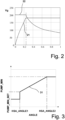
- a parameter, a table, a rule, or a computing algorithm is utilized, which defines the interdependence between the inclination of the working machine and the control signal.
- Said control signal determines the magnitude of the volume flow input to the motor, wherein it is, for example, the volume flow produced by the pump, or the volume flow controlled by the valve.
- the valve is normally a directional valve and preferably a proportional directional valve.
- the control signal or its minimum value is determined by the inclination.
- said interdependence is such that the magnitude of the volume flow controlled to the motor is the greater, the greater the inclination of the working machine.
- said control signal is determined by a control value or e.g.
- the position of the pedal first after the control value or the setting signal generated by the pedal has increased to a value that corresponds to the minimum value of the control signal, or is greater than that.
- the interdependence between the control signal, or setting signal, and the driving speed remains the same when driving on a hillside and on a flat ground.
- the volume flow available to the motor is sufficient to produce, immediately or sufficiently rapidly, a pressure level that is sufficiently high to prevent the rotation of the motor and simultaneously of the wheels of the working machine in such a way that the working machine starts to roll in the wrong direction, that is, downhill.
- the value of the control signal, or its minimum value was not set at a sufficiently high level so that e.g . the pump would produce the required pressure level immediately after the operating brake has been released and the wheels of the working machine can rotate.
- the volume flow provided by the valve has not been sufficient. This is because said rolling does not occur on flat terrain, and the weight of the working machine does not tend to move the working machine but it remains stationary.
- the forest working machine comprises a device for processing tree trunks, for example a felling head which is intended for cutting and felling a standing tree trunk, or a harvester head which is intended for cutting, felling, delimbing, and sawing a standing tree trunk to pieces of desired length.
- the sawn trunks are collected by another known all-terrain mobile forest working machine, such as a forwarder.
- the forwarder comprises a grapple mounted at the end of a boom system, and the trunks are transported in its load space.
- Forest working machines are also known, in which the functions of the harvester and the forwarder are combined.
- the presented solution can be applied in various mobile working machines, particularly in all-terrain mobile working machines.
- forest working machines are feasible, including various harvesters for cutting trees by means of, for example, a felling head, or, if necessary, for processing the trunks as well, for example by means of a harvester head.
- various forwarders for transporting tree trunks or logs are also feasible.
- said working machines comprise wheels which are controlled by hydraulic drive transmission.
- caterpillar tracks can also be applied, also in combination with wheels.
- Figure 8 shows a forest machine, in which the method and the system to be presented in the following can be applied. It is particularly a harvester with a harvester head.
- the harvester of Fig. 8 is provided with frame steering, and it comprises a boom system which is mounted on the frame and whose end is provided with a harvester head for the processing of trunks.
- a control system is applied, which will also be described next.
- Figure 1 shows a solution with a closed circuit and a single-circuit system, particularly a single-motor system.
- hydraulic drive transmission 7 is typically used in the working machines, converting the mechanical power produced by a combustion engine 1 into hydraulic power in a pump 8, wherein the power is proportional to the feed pressure and the volume flow produced by the pump 8.
- the pump 8 is adjustable, so that the volume flow produced can be changed.
- the hydraulic power is utilized in a motor 9 which, in turn, generates a torque and a rotating speed for an output shaft.
- the feed pressure generated by the pump 8 depends on the loading and the power demand of the motor 9.
- the rotational speed of the motor 9 depends on the volume flow produced by the pump 8 and on the setting of the motor 9, if the motor 9 is adjustable, as in Fig. 1 .
- the motor 9 is, in turn, coupled to a gear 10, by means of which the mechanical power is transferred to the wheels of the working machine, for example by means of cardan transmission 11 and differential shafts 12 to bogies 13 equipped with the wheels of the working machine which are mounted on pivotable hubs.
- the drive transmission 7 is controlled by an electronic control system 6 for the working machine, and the combustion engine 1 can be controlled by an electronic control unit (ECU) 14.
- ECU electronice control unit
- the pump 8 is, for example, an angled plate type axial piston pump with adjustable displacement (Vg), where the direction of the volume flow and thereby the rotating direction of the motor and the driving direction of the working machine can be reversed by turning the angled plate of the pump to either side of the neutral centre position.
- the controllable variables are the displacement of the pump and simultaneously the volume flow produced by it.
- the motor is, for example, an axial piston motor of the angled plate or angled shaft type, or a radial piston motor which can also have a fixed volume, in which case the motor is not adjustable. Consequently, the controllable variables are the displacement (Vg) and the rotational speed of the motor.
- control systems are used for controlling working machines.
- the control system controls, among other things, the drive transmission, its hydraulic control circuit, and all the auxiliary functions relating to it.
- the control system in question operates, for example, in the PC operating environment.
- the display and the central processing unit of the control system are placed in the cabin, within reach for the driver.
- the control bus in the control automatics of the control system is based on a CAN bus solution of prior art, in which data is transferred in digital form.
- a sensor 52 or a measuring device is connected to the control system or belongs to its equipment, which device gives a signal that is proportional to the inclination of the working machine, particularly the pitch of the working machine.
- the inclination is defined in the driving direction of the working machine which is typically parallel to the longitudinal direction of the working machine.
- the sensor 52 is fitted so that said signal defines, or it can also be used for determining whether the front end of the working machine is higher or lower than the rear end.
- the sensor 52 is connected, for example, to the chassis or the cabin of the working machine.
- the control system comprises, for example, a predetermined parameter (for example ANGLE) whose value is dependent on the inclination.
- the inclination can be measured continuously or merely in connection with e.g. starting.
- the required application and the software included therein are installed in the central processing unit of the processor based control system comprising the necessary RAM and mass storage.
- the control system utilizes an operating system known as such, under which the application is run.
- the equipment and the operating system comprise the applications and protocol means necessary for communication with other devices.
Landscapes
- Engineering & Computer Science (AREA)
- Mechanical Engineering (AREA)
- Transportation (AREA)
- Chemical & Material Sciences (AREA)
- Combustion & Propulsion (AREA)
- General Engineering & Computer Science (AREA)
- Automation & Control Theory (AREA)
- Health & Medical Sciences (AREA)
- Public Health (AREA)
- Operation Control Of Excavators (AREA)
- Control Of Fluid Gearings (AREA)
- Lifting Devices For Agricultural Implements (AREA)
Claims (8)
- Verfahren zum Steuern eines Systems für eine hydraulische Antriebskraftübertragung in einer Arbeitsmaschine, wobei das System Folgendes umfasst:- ein Steuerungssystem (6) zum Steuern der Funktion,- eine Pumpe (8) zum Erzeugen eines Volumenflusses und eines Zufuhrdrucks, und- einen Motor (9) zum Empfangen des Volumenflusses und Verwenden des Zufuhrdrucks zum Bewegen der Arbeitsmaschine,wobei das Verfahren Folgendes umfasst:- Steuern des Systems mit einem Steuersignal, das einen Wert aufweist, der durch das Steuerungssystem vorgegeben wird, und Beschicken des Motors mit einem Volumenfluss, der von dem Steuersignal abhängig ist,- Halten der Arbeitsmaschine in einem gestoppten und ortsfesten Zustand, und- Messen der Neigung der Arbeitsmaschine in Richtung der Fahrbewegung, wenn die Arbeitsmaschine gestoppt hat, wobei die Neigung von dem Gelände abhängt, auf dem sich die Arbeitsmaschine befindet,dadurch gekennzeichnet, dass das Verfahren Folgendes umfasst:- Steuern der Pumpe mit dem Steuersignal, das einen voreingestellten Mindestwert aufweist, und Verwenden der Pumpe zum Erzeugen eines Volumenflusses, der von dem Steuersignal abhängig ist,- Vergeben eines neuen Mindestwertes an das Steuersignal, der von der Größenordnung der Neigung abhängig ist, und- Steuern der Pumpe mit dem Steuersignal, dessen Wert mindestens dem neuen Mindestwert entspricht, wenn die Arbeitsmaschine gelenkt wird, um sich aus ihrer ortsfesten Position zu bewegen, und die gewählte Fahrtrichtung der Arbeitsmaschine nach oben in Richtung der Neigung zeigt.
- Verfahren zum Steuern eines Systems für eine hydraulische Antriebskraftübertragung in einer Arbeitsmaschine, wobei das System Folgendes umfasst:- ein Steuerungssystem (6) zum Steuern der Funktion,- eine Pumpe (8) zum Erzeugen eines Volumenflusses und eines Zufuhrdrucks,- einen Motor (9) zum Empfangen des Volumenflusses und Verwenden des Zufuhrdrucks zum Bewegen der Arbeitsmaschine, und- ein Ventil (64) zum Steuern der Größenordnung des dem Motor zuzuführenden Volumenflusses,wobei das Verfahren Folgendes umfasst:- Steuern des Systems mit einem Steuersignal, das einen Wert aufweist, der durch das Steuerungssystem vorgegeben wird, und Beschicken des Motors mit einem Volumenfluss, der von dem Steuersignal abhängig ist,- Steuern des Ventils mit dem Steuersignal, und Beschicken des Motors über das Ventil mit einem Volumenfluss, der von dem Steuersignal abhängig ist,- Halten der Arbeitsmaschine in einem gestoppten und ortsfesten Zustand, und- Messen der Neigung der Arbeitsmaschine in Richtung der Fahrbewegung, wenn die Arbeitsmaschine gestoppt hat, wobei die Neigung von dem Gelände abhängt, auf dem sich die Arbeitsmaschine befindet,dadurch gekennzeichnet, dass das Verfahren Folgendes umfasst:- Vergeben eines neuen hinzugegebenen Wertes an das Steuersignal, der von der Größenordnung der Neigung abhängig ist, und- Steuern des Ventils mit dem Steuersignal, dessen Wert dem neuen hinzugegebenen Wert entspricht, wenn die Arbeitsmaschine gelenkt wird, um sich aus ihrer ortsfesten Position zu bewegen, und die gewählte Fahrtrichtung der Arbeitsmaschine nach oben in Richtung der Neigung zeigt.
- Verfahren nach Anspruch 1 oder 2, wobei das Verfahren das Einstellen der Größenordnung des dem Motor zuzuführenden Volumenflusses so umfasst, dass die Größenordnung umso größer ist, je größer die Neigung ist.
- System für eine hydraulische Antriebskraftübertragung in einer Arbeitsmaschine, umfassend:- eine Pumpe (8), die dafür ausgestaltet ist, einen Zufuhrdruck und einen Volumenfluss zu erzeugen,- einen Motor (9), der den Volumenfluss empfängt und den Zufuhrdruck zum Bewegen der Arbeitsmaschine verwendet,- ein Steuerungssystem (6), das dafür ausgestaltet ist, ein Steuersignal zu generieren, das einen Wert aufweist, der ihm durch das Steuerungssystem gegeben wurde und von dem der dem Motor zuzuführende Volumenfluss abhängig ist, wobei die Pumpe dafür ausgestaltet ist, einen Volumenfluss zu erzeugen, der von dem Steuerungssystem abhängig ist,- einen Sensor (52), der in Kontakt mit dem Steuerungssystem (6) steht und dafür ausgelegt ist, wenn die Arbeitsmaschine gestoppt hat, die Neigung der Arbeitsmaschine in Richtung der Antriebsbewegung in Abhängigkeit von dem Gelände, auf dem sich die Arbeitsmaschine befindet, zu messen,wobei das System dadurch gekennzeichnet ist, dass:- das Steuerungssystem dafür ausgestaltet ist, die Pumpe mit dem Steuersignal zu steuern, das einen voreingestellten Mindestwert aufweist,- das Steuerungssystem (6) des Weiteren dafür ausgestaltet ist, dem Steuersignal einen neuen Mindestwert zu geben, der von der Größenordnung der Neigung abhängig ist, und- das Steuersignal, dessen Wert mindestens dem neuen Mindestwert entspricht, wenn die Arbeitsmaschine gelenkt wird, um sich aus ihrer ortsfesten Position zu bewegen, und die gewählte Fahrtrichtung der Arbeitsmaschine nach oben in Richtung der Neigung zeigt.
- System für eine hydraulische Antriebskraftübertragung in einer Arbeitsmaschine, umfassend:- eine Pumpe (8), die dafür ausgestaltet ist, einen Zufuhrdruck und einen Volumenfluss zu erzeugen,- einen Motor (9), der den Volumenfluss empfängt und den Zufuhrdruck zum Bewegen der Arbeitsmaschine verwendet,- ein Steuerungssystem (6), das dafür ausgestaltet ist, ein Steuersignal zu generieren, das einen Wert aufweist, der ihm durch das Steuerungssystem gegeben wurde und von dem der dem Motor zuzuführende Volumenfluss abhängig ist, und- ein Ventil (64), das dafür ausgestaltet ist, die Größenordnung des dem Motor zuzuführenden Volumenflusses zu steuern,wobei- das Steuerungssystem dafür ausgestaltet ist, das Ventil mit dem Steuersignal zu steuern, das einen Wert hat,- das Ventil dafür ausgestaltet ist, den Motor mit einem Volumenfluss zu beschicken, der von dem Steuersignal abhängig ist, und- das System des Weiteren einen Sensor (52) umfasst, der in Kontakt mit dem Steuerungssystem (6) steht und dafür ausgelegt ist, wenn die Arbeitsmaschine gestoppt hat, die Neigung der Arbeitsmaschine in Richtung der Antriebsbewegung in Abhängigkeit von dem Gelände, auf dem sich die Arbeitsmaschine befindet, zu messen,dadurch gekennzeichnet, dass:- das Steuerungssystem (6) des Weiteren dafür ausgestaltet ist, dem Steuersignal einen neuen hinzugefügten Wert zu geben, der von der Größenordnung der Neigung abhängig ist, und- das Steuersignal einen Wert hat, der mindestens dem neuen hinzugefügten Wert entspricht, wenn die Arbeitsmaschine gelenkt wird, um sich aus ihrer ortsfesten Position zu bewegen, und die gewählte Fahrtrichtung der Arbeitsmaschine nach oben in Richtung der Neigung zeigt.
- Steuerungssystem nach Anspruch 4 oder 5, wobei das Steuerungssystem des Weiteren dafür ausgestaltet ist, die Größenordnung des dem Motor zuzuführenden Volumenflusses so einzustellen, dass die Größenordnung umso größer ist, je größer die Neigung ist, und eine Regel, eine Tabelle oder ein Berechnungsalgorithmus, der die gegenseitige Abhängigkeit zwischen dem neuen Wert des Steuersignals und der Neigung definiert, in dem Steuerungssystem gespeichert gehalten wird.
- System nach Anspruch 4, 5 oder 6, wobei das System des Weiteren ein Pedal (3) oder einen Joystick umfasst, von dessen Position das Steuersignal abhängig ist.
- Forstmaschine, die das System nach Anspruch 4 oder 5 umfasst und die eine Forstmaschine ist, die mit einem Fällkopf ausgestattet ist, ein Harvester ist, der mit einem Erntekopf ausgestattet ist, oder ein Forwarder ist, der für den Transport von Baumstämmen ausgestattet ist.
Applications Claiming Priority (1)
| Application Number | Priority Date | Filing Date | Title |
|---|---|---|---|
| FI20115671A FI124159B (fi) | 2011-06-27 | 2011-06-27 | Työkoneen hydraulisen ajovoimansiirron järjestelmä ja menetelmä |
Publications (4)
| Publication Number | Publication Date |
|---|---|
| EP2540550A2 EP2540550A2 (de) | 2013-01-02 |
| EP2540550A3 EP2540550A3 (de) | 2018-05-16 |
| EP2540550B1 EP2540550B1 (de) | 2019-07-24 |
| EP2540550B2 true EP2540550B2 (de) | 2025-01-08 |
Family
ID=44206879
Family Applications (1)
| Application Number | Title | Priority Date | Filing Date |
|---|---|---|---|
| EP12397518.7A Active EP2540550B2 (de) | 2011-06-27 | 2012-06-18 | System und Verfahren für Hydraulikantrieb in einer Arbeitsmaschine |
Country Status (2)
| Country | Link |
|---|---|
| EP (1) | EP2540550B2 (de) |
| FI (2) | FI124159B (de) |
Citations (14)
| Publication number | Priority date | Publication date | Assignee | Title |
|---|---|---|---|---|
| DE4219876A1 (de) † | 1991-06-18 | 1992-12-24 | Juergen Hartig | Radfahrzeug, insbesondere forstmaschine |
| EP0530380A1 (de) † | 1991-03-29 | 1993-03-10 | Hitachi Construction Machinery Co., Ltd. | Steuerungssystem für hydraulische erdbaumaschine |
| JPH05263926A (ja) † | 1992-03-23 | 1993-10-12 | Hitachi Constr Mach Co Ltd | 油圧駆動回路 |
| JPH06191317A (ja) † | 1992-12-25 | 1994-07-12 | Komatsu Ltd | 油圧駆動車のオーバーラン防止方法 |
| JPH07166578A (ja) † | 1993-12-17 | 1995-06-27 | Hitachi Constr Mach Co Ltd | 建設機械 |
| JP2002039374A (ja) † | 2000-07-26 | 2002-02-06 | Sumitomo (Shi) Construction Machinery Manufacturing Co Ltd | アスファルトフィニッシャの坂道逆走防止制御回路及びその制御方法 |
| EP1223069A2 (de) † | 2001-01-16 | 2002-07-17 | Brueninghaus Hydromatik Gmbh | Traktionssteuersystem und Verfahren zur Traktionssteuerung für ein hydrostatisch angetriebenes Fahrzeug |
| US6474063B2 (en) † | 2000-07-28 | 2002-11-05 | Komatsu Ltd. | Travel motor hydraulic control system for a construction machine |
| US20050247504A1 (en) † | 2002-08-28 | 2005-11-10 | Torvec, Inc. | Dual hydraulic machine transmission |
| JP2008169912A (ja) † | 2007-01-11 | 2008-07-24 | Hokuetsu Kogyo Co Ltd | 油圧駆動車の駆動制御方法及び駆動制御装置 |
| EP2123947A1 (de) † | 2006-12-28 | 2009-11-25 | Hitachi Construction Machinery Co., Ltd | Fahrsteuervorrichtung für hydraulikfahrzeug |
| WO2010061384A2 (en) † | 2008-11-25 | 2010-06-03 | Israel Aerospace Industries Ltd. | Towbarless airplane tug |
| EP1577566B1 (de) † | 2004-03-17 | 2010-12-01 | Kobelco Construction Machinery Co., Ltd. | Hydraulisches Steuersystem einer Arbeitsmaschine |
| EP2278193A1 (de) † | 2008-04-14 | 2011-01-26 | Yanmar Co., Ltd. | Arbeitsfahrzeug |
Family Cites Families (3)
| Publication number | Priority date | Publication date | Assignee | Title |
|---|---|---|---|---|
| US5287280A (en) * | 1987-09-14 | 1994-02-15 | Kabushiki Kaisha Komatsu Seisakusho | Method and apparatus for controlling shoe slip of crawler vehicle |
| US20050161090A1 (en) * | 2002-04-26 | 2005-07-28 | Hitachi Construction Machinery Co., Ltd | Travel control device of hydraulically driven vehicle, hydraulically driven vehicle, and wheel hydraulic shovel |
| FI122885B (fi) * | 2005-05-30 | 2012-08-31 | John Deere Forestry Oy | Metsäkoneen suorituskyvyn mittausjärjestelmä |
-
2011
- 2011-06-27 FI FI20115671A patent/FI124159B/fi active IP Right Grant
-
2012
- 2012-06-18 EP EP12397518.7A patent/EP2540550B2/de active Active
- 2012-06-18 FI FIEP12397518.7T patent/FI2540550T4/fi active
Patent Citations (15)
| Publication number | Priority date | Publication date | Assignee | Title |
|---|---|---|---|---|
| EP0530380A1 (de) † | 1991-03-29 | 1993-03-10 | Hitachi Construction Machinery Co., Ltd. | Steuerungssystem für hydraulische erdbaumaschine |
| EP0761491A2 (de) † | 1991-03-29 | 1997-03-12 | Hitachi Construction Machinery Co., Ltd. | Steuervorrichtung für eine hydraulisch angetriebene Baumaschine |
| DE4219876A1 (de) † | 1991-06-18 | 1992-12-24 | Juergen Hartig | Radfahrzeug, insbesondere forstmaschine |
| JPH05263926A (ja) † | 1992-03-23 | 1993-10-12 | Hitachi Constr Mach Co Ltd | 油圧駆動回路 |
| JPH06191317A (ja) † | 1992-12-25 | 1994-07-12 | Komatsu Ltd | 油圧駆動車のオーバーラン防止方法 |
| JPH07166578A (ja) † | 1993-12-17 | 1995-06-27 | Hitachi Constr Mach Co Ltd | 建設機械 |
| JP2002039374A (ja) † | 2000-07-26 | 2002-02-06 | Sumitomo (Shi) Construction Machinery Manufacturing Co Ltd | アスファルトフィニッシャの坂道逆走防止制御回路及びその制御方法 |
| US6474063B2 (en) † | 2000-07-28 | 2002-11-05 | Komatsu Ltd. | Travel motor hydraulic control system for a construction machine |
| EP1223069A2 (de) † | 2001-01-16 | 2002-07-17 | Brueninghaus Hydromatik Gmbh | Traktionssteuersystem und Verfahren zur Traktionssteuerung für ein hydrostatisch angetriebenes Fahrzeug |
| US20050247504A1 (en) † | 2002-08-28 | 2005-11-10 | Torvec, Inc. | Dual hydraulic machine transmission |
| EP1577566B1 (de) † | 2004-03-17 | 2010-12-01 | Kobelco Construction Machinery Co., Ltd. | Hydraulisches Steuersystem einer Arbeitsmaschine |
| EP2123947A1 (de) † | 2006-12-28 | 2009-11-25 | Hitachi Construction Machinery Co., Ltd | Fahrsteuervorrichtung für hydraulikfahrzeug |
| JP2008169912A (ja) † | 2007-01-11 | 2008-07-24 | Hokuetsu Kogyo Co Ltd | 油圧駆動車の駆動制御方法及び駆動制御装置 |
| EP2278193A1 (de) † | 2008-04-14 | 2011-01-26 | Yanmar Co., Ltd. | Arbeitsfahrzeug |
| WO2010061384A2 (en) † | 2008-11-25 | 2010-06-03 | Israel Aerospace Industries Ltd. | Towbarless airplane tug |
Non-Patent Citations (1)
| Title |
|---|
| Zwei Amtsbescheide und zwei Bescheidserwiderungen aus finnischem Prüfunqsverfahren und Patentschrift † |
Also Published As
| Publication number | Publication date |
|---|---|
| FI20115671A0 (sv) | 2011-06-27 |
| EP2540550A3 (de) | 2018-05-16 |
| FI124159B (fi) | 2014-04-15 |
| EP2540550B1 (de) | 2019-07-24 |
| FI2540550T4 (fi) | 2025-02-18 |
| EP2540550A2 (de) | 2013-01-02 |
| FI20115671L (fi) | 2012-12-28 |
Similar Documents
| Publication | Publication Date | Title |
|---|---|---|
| US11787385B2 (en) | Agricultural system and method for preventing roll-back of an agricultural vehicle on a sloped surface | |
| RU2469878C2 (ru) | Электронное устройство управления для привода транспортного средства | |
| US8662212B2 (en) | Four wheel drive system | |
| US6321866B1 (en) | Hydrostatic power distribution/control logic system | |
| US10144421B2 (en) | Vehicle speed control system | |
| US8261544B2 (en) | Control system and method for braking a hydrostatic drive machine | |
| CA2660090A1 (en) | Hybrid vehicle | |
| US20210195834A1 (en) | Grounds maintenance vehicle with traction and steering control system | |
| US9303633B2 (en) | Over-speed control system and method | |
| CN105873784A (zh) | 自行式作业机械及这种作业机械的制动方法 | |
| CN103261536A (zh) | 带有外部制动辅助的闭环驱动回路 | |
| US9545062B2 (en) | Integrated hydraulic system for harvester | |
| WO2009128815A1 (en) | Traction control method and apparatus for a vehicle with independent drives | |
| US20050241873A1 (en) | Method and device for controlling functions of an occupational vehicle | |
| CN107207011A (zh) | 车辆控制系统及方法 | |
| AU2012216572A1 (en) | Swather tractor with rear wheel active steering | |
| CN1698413A (zh) | 用于草皮割草机的牵引力增强系统 | |
| US20110186361A1 (en) | Differential steering control for a continuously variable transmission machine | |
| CA2608563A1 (en) | Engine load management for power machines | |
| EP1716737B1 (de) | Vierradgetriebener Mähdrescher mit Schlupfregelung | |
| CA2296249C (en) | Steering responsive power boost | |
| EP2698519A2 (de) | System und Verfahren zur Steuerung der Drehmomentlast von mehreren Motoren | |
| EP2540550B2 (de) | System und Verfahren für Hydraulikantrieb in einer Arbeitsmaschine | |
| US11021032B2 (en) | Bogie balancing system and method for a work machine | |
| FI125919B (fi) | Työkonejärjestelmä ja menetelmä työkonejärjestelmän ohjauksessa |
Legal Events
| Date | Code | Title | Description |
|---|---|---|---|
| PUAI | Public reference made under article 153(3) epc to a published international application that has entered the european phase |
Free format text: ORIGINAL CODE: 0009012 |
|
| AK | Designated contracting states |
Kind code of ref document: A2 Designated state(s): AL AT BE BG CH CY CZ DE DK EE ES FI FR GB GR HR HU IE IS IT LI LT LU LV MC MK MT NL NO PL PT RO RS SE SI SK SM TR |
|
| AX | Request for extension of the european patent |
Extension state: BA ME |
|
| PUAL | Search report despatched |
Free format text: ORIGINAL CODE: 0009013 |
|
| AK | Designated contracting states |
Kind code of ref document: A3 Designated state(s): AL AT BE BG CH CY CZ DE DK EE ES FI FR GB GR HR HU IE IS IT LI LT LU LV MC MK MT NL NO PL PT RO RS SE SI SK SM TR |
|
| AX | Request for extension of the european patent |
Extension state: BA ME |
|
| RIC1 | Information provided on ipc code assigned before grant |
Ipc: B60K 28/14 20060101AFI20180410BHEP |
|
| STAA | Information on the status of an ep patent application or granted ep patent |
Free format text: STATUS: REQUEST FOR EXAMINATION WAS MADE |
|
| 17P | Request for examination filed |
Effective date: 20181109 |
|
| RBV | Designated contracting states (corrected) |
Designated state(s): AL AT BE BG CH CY CZ DE DK EE ES FI FR GB GR HR HU IE IS IT LI LT LU LV MC MK MT NL NO PL PT RO RS SE SI SK SM TR |
|
| GRAP | Despatch of communication of intention to grant a patent |
Free format text: ORIGINAL CODE: EPIDOSNIGR1 |
|
| STAA | Information on the status of an ep patent application or granted ep patent |
Free format text: STATUS: GRANT OF PATENT IS INTENDED |
|
| INTG | Intention to grant announced |
Effective date: 20190219 |
|
| GRAS | Grant fee paid |
Free format text: ORIGINAL CODE: EPIDOSNIGR3 |
|
| GRAA | (expected) grant |
Free format text: ORIGINAL CODE: 0009210 |
|
| STAA | Information on the status of an ep patent application or granted ep patent |
Free format text: STATUS: THE PATENT HAS BEEN GRANTED |
|
| AK | Designated contracting states |
Kind code of ref document: B1 Designated state(s): AL AT BE BG CH CY CZ DE DK EE ES FI FR GB GR HR HU IE IS IT LI LT LU LV MC MK MT NL NO PL PT RO RS SE SI SK SM TR |
|
| REG | Reference to a national code |
Ref country code: GB Ref legal event code: FG4D |
|
| REG | Reference to a national code |
Ref country code: CH Ref legal event code: EP |
|
| REG | Reference to a national code |
Ref country code: DE Ref legal event code: R096 Ref document number: 602012062229 Country of ref document: DE |
|
| REG | Reference to a national code |
Ref country code: AT Ref legal event code: REF Ref document number: 1157759 Country of ref document: AT Kind code of ref document: T Effective date: 20190815 |
|
| REG | Reference to a national code |
Ref country code: IE Ref legal event code: FG4D |
|
| REG | Reference to a national code |
Ref country code: SE Ref legal event code: TRGR |
|
| REG | Reference to a national code |
Ref country code: NL Ref legal event code: MP Effective date: 20190724 |
|
| REG | Reference to a national code |
Ref country code: LT Ref legal event code: MG4D |
|
| REG | Reference to a national code |
Ref country code: AT Ref legal event code: MK05 Ref document number: 1157759 Country of ref document: AT Kind code of ref document: T Effective date: 20190724 |
|
| PG25 | Lapsed in a contracting state [announced via postgrant information from national office to epo] |
Ref country code: NO Free format text: LAPSE BECAUSE OF FAILURE TO SUBMIT A TRANSLATION OF THE DESCRIPTION OR TO PAY THE FEE WITHIN THE PRESCRIBED TIME-LIMIT Effective date: 20191024 Ref country code: BG Free format text: LAPSE BECAUSE OF FAILURE TO SUBMIT A TRANSLATION OF THE DESCRIPTION OR TO PAY THE FEE WITHIN THE PRESCRIBED TIME-LIMIT Effective date: 20191024 Ref country code: AT Free format text: LAPSE BECAUSE OF FAILURE TO SUBMIT A TRANSLATION OF THE DESCRIPTION OR TO PAY THE FEE WITHIN THE PRESCRIBED TIME-LIMIT Effective date: 20190724 Ref country code: PT Free format text: LAPSE BECAUSE OF FAILURE TO SUBMIT A TRANSLATION OF THE DESCRIPTION OR TO PAY THE FEE WITHIN THE PRESCRIBED TIME-LIMIT Effective date: 20191125 Ref country code: NL Free format text: LAPSE BECAUSE OF FAILURE TO SUBMIT A TRANSLATION OF THE DESCRIPTION OR TO PAY THE FEE WITHIN THE PRESCRIBED TIME-LIMIT Effective date: 20190724 Ref country code: HR Free format text: LAPSE BECAUSE OF FAILURE TO SUBMIT A TRANSLATION OF THE DESCRIPTION OR TO PAY THE FEE WITHIN THE PRESCRIBED TIME-LIMIT Effective date: 20190724 Ref country code: LT Free format text: LAPSE BECAUSE OF FAILURE TO SUBMIT A TRANSLATION OF THE DESCRIPTION OR TO PAY THE FEE WITHIN THE PRESCRIBED TIME-LIMIT Effective date: 20190724 |
|
| PG25 | Lapsed in a contracting state [announced via postgrant information from national office to epo] |
Ref country code: RS Free format text: LAPSE BECAUSE OF FAILURE TO SUBMIT A TRANSLATION OF THE DESCRIPTION OR TO PAY THE FEE WITHIN THE PRESCRIBED TIME-LIMIT Effective date: 20190724 Ref country code: AL Free format text: LAPSE BECAUSE OF FAILURE TO SUBMIT A TRANSLATION OF THE DESCRIPTION OR TO PAY THE FEE WITHIN THE PRESCRIBED TIME-LIMIT Effective date: 20190724 Ref country code: ES Free format text: LAPSE BECAUSE OF FAILURE TO SUBMIT A TRANSLATION OF THE DESCRIPTION OR TO PAY THE FEE WITHIN THE PRESCRIBED TIME-LIMIT Effective date: 20190724 Ref country code: LV Free format text: LAPSE BECAUSE OF FAILURE TO SUBMIT A TRANSLATION OF THE DESCRIPTION OR TO PAY THE FEE WITHIN THE PRESCRIBED TIME-LIMIT Effective date: 20190724 Ref country code: GR Free format text: LAPSE BECAUSE OF FAILURE TO SUBMIT A TRANSLATION OF THE DESCRIPTION OR TO PAY THE FEE WITHIN THE PRESCRIBED TIME-LIMIT Effective date: 20191025 Ref country code: IS Free format text: LAPSE BECAUSE OF FAILURE TO SUBMIT A TRANSLATION OF THE DESCRIPTION OR TO PAY THE FEE WITHIN THE PRESCRIBED TIME-LIMIT Effective date: 20191124 |
|
| PG25 | Lapsed in a contracting state [announced via postgrant information from national office to epo] |
Ref country code: TR Free format text: LAPSE BECAUSE OF FAILURE TO SUBMIT A TRANSLATION OF THE DESCRIPTION OR TO PAY THE FEE WITHIN THE PRESCRIBED TIME-LIMIT Effective date: 20190724 |
|
| REG | Reference to a national code |
Ref country code: DE Ref legal event code: R026 Ref document number: 602012062229 Country of ref document: DE |
|
| PG25 | Lapsed in a contracting state [announced via postgrant information from national office to epo] |
Ref country code: PL Free format text: LAPSE BECAUSE OF FAILURE TO SUBMIT A TRANSLATION OF THE DESCRIPTION OR TO PAY THE FEE WITHIN THE PRESCRIBED TIME-LIMIT Effective date: 20190724 Ref country code: DK Free format text: LAPSE BECAUSE OF FAILURE TO SUBMIT A TRANSLATION OF THE DESCRIPTION OR TO PAY THE FEE WITHIN THE PRESCRIBED TIME-LIMIT Effective date: 20190724 Ref country code: IT Free format text: LAPSE BECAUSE OF FAILURE TO SUBMIT A TRANSLATION OF THE DESCRIPTION OR TO PAY THE FEE WITHIN THE PRESCRIBED TIME-LIMIT Effective date: 20190724 Ref country code: RO Free format text: LAPSE BECAUSE OF FAILURE TO SUBMIT A TRANSLATION OF THE DESCRIPTION OR TO PAY THE FEE WITHIN THE PRESCRIBED TIME-LIMIT Effective date: 20190724 Ref country code: EE Free format text: LAPSE BECAUSE OF FAILURE TO SUBMIT A TRANSLATION OF THE DESCRIPTION OR TO PAY THE FEE WITHIN THE PRESCRIBED TIME-LIMIT Effective date: 20190724 |
|
| PLBI | Opposition filed |
Free format text: ORIGINAL CODE: 0009260 |
|
| PG25 | Lapsed in a contracting state [announced via postgrant information from national office to epo] |
Ref country code: SK Free format text: LAPSE BECAUSE OF FAILURE TO SUBMIT A TRANSLATION OF THE DESCRIPTION OR TO PAY THE FEE WITHIN THE PRESCRIBED TIME-LIMIT Effective date: 20190724 Ref country code: SM Free format text: LAPSE BECAUSE OF FAILURE TO SUBMIT A TRANSLATION OF THE DESCRIPTION OR TO PAY THE FEE WITHIN THE PRESCRIBED TIME-LIMIT Effective date: 20190724 Ref country code: CZ Free format text: LAPSE BECAUSE OF FAILURE TO SUBMIT A TRANSLATION OF THE DESCRIPTION OR TO PAY THE FEE WITHIN THE PRESCRIBED TIME-LIMIT Effective date: 20190724 Ref country code: IS Free format text: LAPSE BECAUSE OF FAILURE TO SUBMIT A TRANSLATION OF THE DESCRIPTION OR TO PAY THE FEE WITHIN THE PRESCRIBED TIME-LIMIT Effective date: 20200224 |
|
| REG | Reference to a national code |
Ref country code: FI Ref legal event code: MDE Opponent name: BOSCH REXROTH AG |
|
| 26 | Opposition filed |
Opponent name: BOSCH REXROTH AG Effective date: 20200424 |
|
| PLAX | Notice of opposition and request to file observation + time limit sent |
Free format text: ORIGINAL CODE: EPIDOSNOBS2 |
|
| PG2D | Information on lapse in contracting state deleted |
Ref country code: IS |
|
| PG25 | Lapsed in a contracting state [announced via postgrant information from national office to epo] |
Ref country code: SI Free format text: LAPSE BECAUSE OF FAILURE TO SUBMIT A TRANSLATION OF THE DESCRIPTION OR TO PAY THE FEE WITHIN THE PRESCRIBED TIME-LIMIT Effective date: 20190724 |
|
| PLBB | Reply of patent proprietor to notice(s) of opposition received |
Free format text: ORIGINAL CODE: EPIDOSNOBS3 |
|
| PG25 | Lapsed in a contracting state [announced via postgrant information from national office to epo] |
Ref country code: MC Free format text: LAPSE BECAUSE OF FAILURE TO SUBMIT A TRANSLATION OF THE DESCRIPTION OR TO PAY THE FEE WITHIN THE PRESCRIBED TIME-LIMIT Effective date: 20190724 |
|
| REG | Reference to a national code |
Ref country code: CH Ref legal event code: PL |
|
| PG25 | Lapsed in a contracting state [announced via postgrant information from national office to epo] |
Ref country code: LU Free format text: LAPSE BECAUSE OF NON-PAYMENT OF DUE FEES Effective date: 20200618 |
|
| REG | Reference to a national code |
Ref country code: BE Ref legal event code: MM Effective date: 20200630 |
|
| PG25 | Lapsed in a contracting state [announced via postgrant information from national office to epo] |
Ref country code: CH Free format text: LAPSE BECAUSE OF NON-PAYMENT OF DUE FEES Effective date: 20200630 Ref country code: IE Free format text: LAPSE BECAUSE OF NON-PAYMENT OF DUE FEES Effective date: 20200618 Ref country code: LI Free format text: LAPSE BECAUSE OF NON-PAYMENT OF DUE FEES Effective date: 20200630 Ref country code: FR Free format text: LAPSE BECAUSE OF NON-PAYMENT OF DUE FEES Effective date: 20200630 |
|
| PG25 | Lapsed in a contracting state [announced via postgrant information from national office to epo] |
Ref country code: BE Free format text: LAPSE BECAUSE OF NON-PAYMENT OF DUE FEES Effective date: 20200630 |
|
| PG25 | Lapsed in a contracting state [announced via postgrant information from national office to epo] |
Ref country code: MT Free format text: LAPSE BECAUSE OF FAILURE TO SUBMIT A TRANSLATION OF THE DESCRIPTION OR TO PAY THE FEE WITHIN THE PRESCRIBED TIME-LIMIT Effective date: 20190724 Ref country code: CY Free format text: LAPSE BECAUSE OF FAILURE TO SUBMIT A TRANSLATION OF THE DESCRIPTION OR TO PAY THE FEE WITHIN THE PRESCRIBED TIME-LIMIT Effective date: 20190724 |
|
| PG25 | Lapsed in a contracting state [announced via postgrant information from national office to epo] |
Ref country code: MK Free format text: LAPSE BECAUSE OF FAILURE TO SUBMIT A TRANSLATION OF THE DESCRIPTION OR TO PAY THE FEE WITHIN THE PRESCRIBED TIME-LIMIT Effective date: 20190724 |
|
| PLAB | Opposition data, opponent's data or that of the opponent's representative modified |
Free format text: ORIGINAL CODE: 0009299OPPO |
|
| APBM | Appeal reference recorded |
Free format text: ORIGINAL CODE: EPIDOSNREFNO |
|
| APBP | Date of receipt of notice of appeal recorded |
Free format text: ORIGINAL CODE: EPIDOSNNOA2O |
|
| APAH | Appeal reference modified |
Free format text: ORIGINAL CODE: EPIDOSCREFNO |
|
| R26 | Opposition filed (corrected) |
Opponent name: BOSCH REXROTH AG Effective date: 20200424 |
|
| APBQ | Date of receipt of statement of grounds of appeal recorded |
Free format text: ORIGINAL CODE: EPIDOSNNOA3O |
|
| APBU | Appeal procedure closed |
Free format text: ORIGINAL CODE: EPIDOSNNOA9O |
|
| PUAH | Patent maintained in amended form |
Free format text: ORIGINAL CODE: 0009272 |
|
| STAA | Information on the status of an ep patent application or granted ep patent |
Free format text: STATUS: PATENT MAINTAINED AS AMENDED |
|
| 27A | Patent maintained in amended form |
Effective date: 20250108 |
|
| AK | Designated contracting states |
Kind code of ref document: B2 Designated state(s): AL AT BE BG CH CY CZ DE DK EE ES FI FR GB GR HR HU IE IS IT LI LT LU LV MC MK MT NL NO PL PT RO RS SE SI SK SM TR |
|
| REG | Reference to a national code |
Ref country code: DE Ref legal event code: R102 Ref document number: 602012062229 Country of ref document: DE |
|
| REG | Reference to a national code |
Ref country code: SE Ref legal event code: RPEO |
|
| PGFP | Annual fee paid to national office [announced via postgrant information from national office to epo] |
Ref country code: FI Payment date: 20250625 Year of fee payment: 14 |
|
| PGFP | Annual fee paid to national office [announced via postgrant information from national office to epo] |
Ref country code: DE Payment date: 20250521 Year of fee payment: 14 |
|
| PGFP | Annual fee paid to national office [announced via postgrant information from national office to epo] |
Ref country code: GB Payment date: 20250627 Year of fee payment: 14 |
|
| PGFP | Annual fee paid to national office [announced via postgrant information from national office to epo] |
Ref country code: SE Payment date: 20250627 Year of fee payment: 14 |