EP2698519A2 - System und Verfahren zur Steuerung der Drehmomentlast von mehreren Motoren - Google Patents
System und Verfahren zur Steuerung der Drehmomentlast von mehreren Motoren Download PDFInfo
- Publication number
- EP2698519A2 EP2698519A2 EP13003639.5A EP13003639A EP2698519A2 EP 2698519 A2 EP2698519 A2 EP 2698519A2 EP 13003639 A EP13003639 A EP 13003639A EP 2698519 A2 EP2698519 A2 EP 2698519A2
- Authority
- EP
- European Patent Office
- Prior art keywords
- engine
- torque
- engine speed
- torque output
- responsive
- Prior art date
- Legal status (The legal status is an assumption and is not a legal conclusion. Google has not performed a legal analysis and makes no representation as to the accuracy of the status listed.)
- Withdrawn
Links
- 238000000034 method Methods 0.000 title claims abstract description 24
- 238000009826 distribution Methods 0.000 claims abstract description 7
- 238000004891 communication Methods 0.000 claims description 10
- 230000009977 dual effect Effects 0.000 description 10
- 230000005540 biological transmission Effects 0.000 description 6
- 239000000463 material Substances 0.000 description 6
- 238000011217 control strategy Methods 0.000 description 4
- 230000004044 response Effects 0.000 description 3
- 238000003860 storage Methods 0.000 description 3
- 238000004364 calculation method Methods 0.000 description 2
- 230000008878 coupling Effects 0.000 description 2
- 238000010168 coupling process Methods 0.000 description 2
- 238000005859 coupling reaction Methods 0.000 description 2
- 238000005520 cutting process Methods 0.000 description 2
- 238000010586 diagram Methods 0.000 description 2
- 239000002689 soil Substances 0.000 description 2
- 238000002485 combustion reaction Methods 0.000 description 1
- 238000013500 data storage Methods 0.000 description 1
- 238000000151 deposition Methods 0.000 description 1
- 238000013461 design Methods 0.000 description 1
- -1 for example Substances 0.000 description 1
- 239000000446 fuel Substances 0.000 description 1
- 230000006870 function Effects 0.000 description 1
- 238000011022 operating instruction Methods 0.000 description 1
- 238000012545 processing Methods 0.000 description 1
- 238000012360 testing method Methods 0.000 description 1
Images


Classifications
-
- F—MECHANICAL ENGINEERING; LIGHTING; HEATING; WEAPONS; BLASTING
- F02—COMBUSTION ENGINES; HOT-GAS OR COMBUSTION-PRODUCT ENGINE PLANTS
- F02D—CONTROLLING COMBUSTION ENGINES
- F02D25/00—Controlling two or more co-operating engines
-
- F—MECHANICAL ENGINEERING; LIGHTING; HEATING; WEAPONS; BLASTING
- F02—COMBUSTION ENGINES; HOT-GAS OR COMBUSTION-PRODUCT ENGINE PLANTS
- F02D—CONTROLLING COMBUSTION ENGINES
- F02D41/00—Electrical control of supply of combustible mixture or its constituents
- F02D41/02—Circuit arrangements for generating control signals
- F02D41/14—Introducing closed-loop corrections
- F02D41/1497—With detection of the mechanical response of the engine
-
- F—MECHANICAL ENGINEERING; LIGHTING; HEATING; WEAPONS; BLASTING
- F02—COMBUSTION ENGINES; HOT-GAS OR COMBUSTION-PRODUCT ENGINE PLANTS
- F02B—INTERNAL-COMBUSTION PISTON ENGINES; COMBUSTION ENGINES IN GENERAL
- F02B73/00—Combinations of two or more engines, not otherwise provided for
-
- F—MECHANICAL ENGINEERING; LIGHTING; HEATING; WEAPONS; BLASTING
- F02—COMBUSTION ENGINES; HOT-GAS OR COMBUSTION-PRODUCT ENGINE PLANTS
- F02D—CONTROLLING COMBUSTION ENGINES
- F02D41/00—Electrical control of supply of combustible mixture or its constituents
- F02D41/02—Circuit arrangements for generating control signals
- F02D41/14—Introducing closed-loop corrections
- F02D41/1401—Introducing closed-loop corrections characterised by the control or regulation method
- F02D2041/1409—Introducing closed-loop corrections characterised by the control or regulation method using at least a proportional, integral or derivative controller
-
- F—MECHANICAL ENGINEERING; LIGHTING; HEATING; WEAPONS; BLASTING
- F02—COMBUSTION ENGINES; HOT-GAS OR COMBUSTION-PRODUCT ENGINE PLANTS
- F02D—CONTROLLING COMBUSTION ENGINES
- F02D2200/00—Input parameters for engine control
- F02D2200/02—Input parameters for engine control the parameters being related to the engine
- F02D2200/10—Parameters related to the engine output, e.g. engine torque or engine speed
- F02D2200/1002—Output torque
-
- F—MECHANICAL ENGINEERING; LIGHTING; HEATING; WEAPONS; BLASTING
- F02—COMBUSTION ENGINES; HOT-GAS OR COMBUSTION-PRODUCT ENGINE PLANTS
- F02D—CONTROLLING COMBUSTION ENGINES
- F02D2200/00—Input parameters for engine control
- F02D2200/02—Input parameters for engine control the parameters being related to the engine
- F02D2200/10—Parameters related to the engine output, e.g. engine torque or engine speed
- F02D2200/101—Engine speed
-
- F—MECHANICAL ENGINEERING; LIGHTING; HEATING; WEAPONS; BLASTING
- F02—COMBUSTION ENGINES; HOT-GAS OR COMBUSTION-PRODUCT ENGINE PLANTS
- F02D—CONTROLLING COMBUSTION ENGINES
- F02D2250/00—Engine control related to specific problems or objectives
- F02D2250/18—Control of the engine output torque
Definitions
- the present disclosure relates generally to a system and method for controlling torque load of multiple engines, and more particularly to adjusting engine torque produced by each engine toward a desired contribution portion of a combined torque output of the multiple engines.
- a tractor scraper is a type of earthmoving equipment used to perform a variety of operations, including loading, or capturing, material, such as soil, at one location and dumping, or depositing, the material at another location.
- the scraper portion of the machine may include a bowl within which material may be captured, and a cutting edge located adjacent a cut opening of the bowl.
- scrapers are often pulled by a tractor, such as a wheeled or track type tractor having a first powertrain for propelling the machine.
- scrapers may provide their own traction via a second powertrain that applies rim pull, or power, to the wheels of the scraper.
- Such machines including both tractor and scraper powertrains, may be referred to as dual powertrain machines.
- the scraper powertrain may be capable of pushing the tractor powertrain.
- Land well service rigs are one of many additional examples of multiple engines providing a common source of power.
- U.S. Patent No. 4,137,721 to Glennon et al. discusses a control system for two gas turbine engines of a helicopter power plant.
- the control system adjusts fueling to the gas turbine engines based on speed error signals and a torque feedback.
- the torque feedback generally includes a difference, if any, between the torque output of each of the engines.
- the speed error and torque feedback are summed and input into proportional and integral control channels.
- Glennon may provide one strategy for controlling plural engines, the torque feedback aspect appears tightly integrated with the fueling control and, thus, may not be readily provided as a retrofit. Further, there is a continuing need for improved control strategies, including torque load control strategies, for multiple engine systems.
- the present disclosure is directed to one or more of the problems or issues set forth above.
- a method of controlling torque load of multiple engines according to a torque distribution algorithm includes determining a combined torque output value responsive to actual torque outputs of first and second engines.
- a desired torque output for the first engine is determined responsive to a first desired contribution portion of the combined torque output value, and a desired torque output for the second engine is determined responsive to a second desired contribution portion of the combined torque output value.
- a torque error for each of the first and second engines is determined responsive to a difference between the desired torque output for a respective one of the first and second engines and the actual torque output from the respective engine. Operation of each of the first and second engines is controlled responsive to the respective torque error.
- a multiple engine system in another aspect, includes a first engine and a second engine.
- a first proportional-integral controller is in communication with the first engine and is configured to receive as a first input a first torque error and provide as a first output a first engine speed adjustment value.
- the first torque error corresponds to a difference between a first desired torque output and a first actual torque output of the first engine, and the first desired torque output corresponds to a first desired contribution portion of a combined torque output of the first and second engines.
- a second proportional-integral controller is in communication with the second engine and is configured to receive as a second input a second torque error and provide as a second output a second engine speed adjustment value.
- the second torque error corresponds to a difference between a second desired torque output and a second actual torque output of the second engine, and the second desired torque output corresponds to a second desired contribution portion of the combined torque output.
- a dual powertrain machine in another aspect, includes a first powertrain including a first transmission coupling a first engine and a first set of ground engaging elements, and a second powertrain including a second transmission coupling a second engine and a second set of ground engaging elements.
- An electronic controller is in communication with the first powertrain and the second powertrain and is configured to determine a combined torque output value responsive to a first actual torque output of the first engine and a second actual torque output of the second engine.
- the electronic controller is also configured to determine a first desired torque output for the first engine responsive to a first desired contribution portion of the combined torque output value, determine a second desired torque output for the second engine responsive to a second desired contribution portion of the combined torque output value, determine a first torque error for the first engine responsive to a difference between the first desired torque output and the first actual torque output, and determine a second torque error for the second engine responsive to a difference between the second desired torque output and the second actual torque output.
- a first engine speed of the first engine is adjusted responsive to the first torque error, while a second engine speed of the second engine is adjusted responsive to the second torque error.
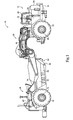
- FIG. 1 An exemplary embodiment of a machine 10 is shown generally in Figure 1 .
- the machine 10, shown as a tractor scraper may be an articulated machine having a front portion 12 pivotably attached to a rear portion 14 at an articulated hitch 16.
- the front portion 12 may include a tractor 18 having a frame 20 supporting, among other systems and components, a first set of ground engaging elements 22, an operator control station 24, and a front engine compartment 26.
- the front engine compartment 26 may house portions of a first propulsion system, discussed below with reference to Figure 2 , which may provide propulsion means for driving the first set of ground engaging elements 22 through a front axle assembly 28.
- the rear portion 14 may include a scraper 30 having a frame 32 supporting at least a rear axle assembly 34 about which a scraper bowl 36 may pivot.
- the frame 32 may also support a second set of ground engaging elements 38, which may be propelled by the rear axle assembly 34 using a second propulsion system housed within a rear engine compartment 40.
- the second propulsion system discussed below in greater detail, may thus, according to such tandem powered arrangements, provide its own power, or traction, for the second set of ground engaging elements 38.
- the machine 10, having two propulsion systems may also be referred to herein as a dual powertrain machine.
- the scraper bowl 36 may define a cut opening 42, at a front portion of the scraper bowl 36, with a cutting edge, such as a scraper blade 44, positioned adjacent the cut opening 42.
- the scraper bowl 36 may be pivoted downward about the axle assembly 34, such as by using one or more scraper bowl actuators or cylinders 46, to engage the scraper blade 44 with material, such as, for example, soil.
- material such as, for example, soil.
- scraper 30 may include additional components or features, such as, for example, an auger attachment, elevator mechanism, or ejector.
- the operator control station 24, introduced above, may be supported on the front frame 20, and may include known devices, such as, for example, a seat assembly, steering device, and one or more operator displays that facilitate operator control of the tractor 18 and/or scraper 30.
- the operator control station 24 may include various other devices, including, but not limited to, one or more machine operation controllers.
- a machine operation controller 48 such as a throttle, may be provided for selecting or controlling an engine speed of an internal combustion engine provided within either or both of engine compartments 26 and 40.
- one or more machine operation controllers may be provided for controlling operation of the scraper 30, such as by controlling movement of the scraper bowl actuators or cylinders 46. Additional controls and devices, as should be appreciated, may also be provided within the operator control station 24 for controlling various operational aspects of the tractor 18 and/or scraper 30 using mechanical, hydraulic, and/or electronic control means.
- the multiple engine system 60 may include a first electronically controlled powertrain 62, also referred to as a front or primary powertrain, and a second electronically controlled powertrain 64, also referred to as a rear or secondary powertrain.
- the first powertrain 62 may include a first electronically controlled engine 66 housed within the front engine compartment 26 and coupled to the ground engaging elements 22 via a first electronically controlled transmission 68.
- the second powertrain 64 may be similar to the first powertrain 62 and may include a second electronically controlled engine 70 housed within the rear engine compartment 40 and coupled to the ground engaging elements 38 via a second electronically controlled transmission 72.
- simplified versions of the first and second powertrains 62 and 64 are shown, it should be appreciated that each of the first and second powertrains 62 and 64 may include additional and/or alternative components without deviating from the scope of the present disclosure.
- the multiple engine system 10 may also include a control system 74 including one or more electronic controllers.
- the first powertrain 62 may include at least a first engine controller 76
- the second powertrain 64 may similarly include at least a second engine controller 78.
- the control system 74 may include more or less electronic controllers, as necessary, to provide desired electronic control of engine and/or powertrain operations.
- a main electronic controller 80 may be provided, or one of the electronic controllers 76 and 78 may be designated the main controller, to coordinate functions and/or facilitate communication within the control system 74. It should be appreciated that the particular control system 74 presented herein is provided for exemplary purposes only.
- Each of the electronic controllers 76, 78, and 80 may be of standard design and may include a processor, such as, for example, a central processing unit, a memory, and an input/output circuit that facilitates communication internal and external to the electronic controllers 76, 78, and 80.
- the processor may control operation of each of the electronic controllers 76, 78, and 80 by executing operating instructions, such as, for example, computer readable program code stored in the memory, wherein operations may be initiated internally or externally to the electronic controllers 76, 78, and 80.
- Control schemes may be utilized that monitor outputs of systems or devices, such as, for example, sensors, actuators, or control units, via the input/output circuit to control inputs to various other systems or devices.
- the main electronic controller 80 may be in communication with, and may utilize input from, the throttle 48 to control speed of the engines 66 and 70.
- the memory may comprise temporary storage areas, such as, for example, cache, virtual memory, or random access memory, or permanent storage areas, such as, for example, read-only memory, removable drives, network/internet storage, hard drives, flash memory, memory sticks, or any other known volatile or non-volatile data storage devices.
- temporary storage areas such as, for example, cache, virtual memory, or random access memory
- permanent storage areas such as, for example, read-only memory, removable drives, network/internet storage, hard drives, flash memory, memory sticks, or any other known volatile or non-volatile data storage devices.
- the main electronic controller 80 may include a processor 82 and a memory 84, both having capabilities similar to those described above.
- the processor 82 may access program code stored in memory 84 to perform and/or coordinate machine and, more specifically, engine operations. While engine electronic controllers 76 and 78 may directly control operation of the respective engines 66 and 70, the main electronic controller 80 may control or coordinate operations of the machine 10, including facilitating communication, such as using communication lines 86 of a Controller Area Network (CAN), among sensors, controllers, and displays of the machine 10 and/or multiple engine system 60.
- CAN Controller Area Network
- the main electronic controller 80 may coordinate control of the two powertrains 62 and 64, including first and second engines 66 and 70.
- the engine electronic controllers 76 and 78 may communicate directly with one another.
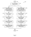
- FIG. 3 there is shown a logic flow diagram 100 representing an exemplary method for controlling torque load of the multiple engine system 60, or an alternative system including multiple engines powering a common load.
- the method may be implemented by any one or more of the electronic controllers 76, 78, and 80, or alternative electronic controllers, as will be described herein.
- the steps implementing the disclosed method may be in the form of computer readable program code stored in the memory 84 of the main electronic controller 80 and executed by the processor 82 of the main electronic controller 80, or other computer usable medium.
- the method may run continuously or may be initiated in response to one or more predetermined events.
- the method begins at a START, Box 102. From Box 102, the method proceeds to Box 104, which includes the step of determining a combined torque output value.
- the combined torque output value may represent the total torque output of the multiple engine system 60, including torque produced by both of the first engine 66 and the second engine 70.
- the torque may be measured using torque sensors or may be calculated as an estimated torque output based on engine calculations or may be based on a reported fuel rate. Those skilled in the art will appreciate that various means exist for arriving at actual torque output values for each of the engines 66 and 70.
- the method proceeds to Boxes 106 and 108.
- a first desired torque output for the first engine 66 is determined based on a first desired contribution portion of the combined torque output value calculated at Box 104. For example, if it is desirable to balance, or equally distribute, torque load among the engines 66 and 70 of the multiple engine system 60, the first desired contribution portion may be set accordingly. In particular, since the multiple engine system 60 includes two engines 66 and 70 it may be desirable to set the first desired contribution portion to 50%. Similarly, a second desired torque output of the second engine 70 may be determined, at Box 108, based on a second desired contribution portion of the combined torque output value. Although the second desired contribution portion may also be set to 50%, it should be appreciated that the desired contribution portions may vary, depending on the particular application. Thus, the first and second desired contribution portions may be set to equal values, as described, or unequal values.
- First and second torque errors are then calculated at respective Boxes 110 and 112.
- the first torque error may include a difference between the first desired torque output of the first engine 66 and the actual torque output of the first engine 66, both of which are described above.
- the second torque error may include a difference between the second desired torque output of the second engine 70 and the actual torque output of the second engine 70.
- Each of the torque error values may then be used to determine engine speed adjustment values for each of the engines 66 and 70.
- a first engine speed adjustment value may be calculated for the first engine 66 in response to the first torque error of the first engine 66.
- a second engine speed adjustment value may be calculated for the second engine 70 in response to the second torque error of the second engine 70.
- the first and second engine speed adjustment values are then used to control operation of the first and second engines 66 and 70.
- a first adjusted desired engine speed command may be generated for the first engine 66.
- the first adjusted desired engine speed command may represent an adjustment of a desired engine speed value according to the first engine speed adjustment value.
- a second adjusted desired engine speed command may be generated for the second engine 70, and may represent an adjustment of the desired engine speed value according to the second engine speed adjustment value.
- the desired engine speed value may be set responsive to a position of the operator throttle 48, with the desired engine speed value being the same for both engines 66 and 70.
- the first and second engines 66 and 70 are then controlled using the respective adjusted desired engine speed commands, as shown at Boxes 122 and 124.
- the engine speed of the first engine 66 may be maintained below a target speed, as indicated by the first adjusted desired engine speed command, using an electronically controlled engine governor.
- the engine speed of the second engine 70 may also be maintained below a target speed, as indicated by the second adjusted desired engine speed command.
- the method then proceeds to an end at Box 126.
- the method may run continuously to adjust the speed of the engines 66 and 70 and, thus, control, or balance, the torque produced.
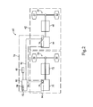
- a torque distribution algorithm 130 may be executed on an electronic controller 132, which may correspond to one or more of the electronic controllers 76, 78, and 80.
- the controller 132 may receive as inputs a first engine speed 134, a first engine torque 136, a second engine torque 138, a second engine speed 140, and a desired engine speed value 142.
- the engine speeds 134 and 140 and the engine torques 136 and 138 may each be sensed or calculated using known means, while the desired engine speed value 142 may be determined based on an operator input, such as the throttle 48.
- the first and second engine torques 136 and 138 may be combined, or added, to arrive at a combined torque output value 144.
- the combined torque output value 144 thus, represents the total torque produced by the multiple engine system 60.
- a desired contribution portion such as desired contribution portion 146, may be used to distribute the combined torque output value 144 among the engines 66 and 70 of the multiple engine system 60.
- the combined torque output value 144 may be divided in half, as shown, to ascertain a first desired torque output 148 for the first engine 66 and a second desired torque output 150 for the second engine 70.
- the desired contribution portion 146 is the same for both engines 66 and 70, according to the exemplary embodiment, it should be appreciated that alternative embodiments may require desired contribution portions 146 that are different for each of the engines 66 and 70. It should also be appreciated that alternative embodiments may require a distribution of torque among more engines than just first and second engines 66 and 70.
- a difference between the first desired torque output 148 and the first engine torque 136 is determined, at a summation block 152, to arrive at a first torque error 154.
- a difference between the second desired torque output 150 and the second engine torque 138 is determined, at a summation block 156, to arrive at a second torque error 158.
- the first torque error 154 along with the first engine speed 134, may be fed into a first proportional-integral (PI) controller 160, or other similar controller, as shown.
- the first PI controller 160 may reference a first gain scheduling map 162, an example of which will be discussed below, to select a gain corresponding to the first engine speed 134 to be used by the controller 132.
- the PI controller 160 may operate in a known fashion to ultimately adjust an engine speed of the first engine 66 according to the selected gain based on the first torque error 154. As such, the PI controller 160 may output a first engine speed adjustment value 164, which is combined with the desired engine speed value 142 at a summation block 166, to generate a first engine adjusted desired engine speed command 168. The first engine adjusted desired engine speed command 168 is then used to control the first engine 66 in a known manner.
- the second torque error 158 may be fed into a second PI controller 170.
- the second PI controller 170 may reference a second gain scheduling map 172, which may be the same as the first gain scheduling map 162, to select a gain corresponding to the second engine speed 140 to be used by the controller 170.
- the PI controller 170 may adjust an engine speed of the second engine 70 according to the selected gain based on the second torque error 158.
- the PI controller 170 may output a second engine speed adjustment value 174, which is combined with the desired engine speed value 142 at a summation block 176, to generate a second engine adjusted desired engine speed command 178.
- the second engine adjusted desired engine speed command 178 is then used to control the second engine 70 in a known manner.
- an exemplary gain scheduling map 190 relating gain values 192 to engine speed values 194 is shown.
- the gain values 192 may decrease as the engine speed values 194 increase.
- the gain values 192 may increase as the engine speed values 194 increase.
- the gain values 192 provided in the gain scheduling map 190 are provided for exemplary purposes only.
- the gain values 192 are configurable and may be arrived at through testing in order to provide desired operation of the multiple engine system 60. For example, according to some embodiments, improved stability at higher speeds may be achieved by utilizing gain values 192 that decrease as engine speed values 194 increase. Further, improved operation may result from using gain values 192 that are selected based on both current engine speed and desired torque.
- the present disclosure may be applicable to multiple engine systems, which may include machines and/or systems utilizing multiple engines to power a common load.
- the present disclosure may be applicable to a dual powertrain machine including a first powertrain for driving a first set of ground engaging elements and a second powertrain for driving a second set of ground engaging elements.
- the present disclosure may be applicable to strategies for controlling the torque load of the engines within the multiple engine system.
- a dual powertrain machine 10 may be an articulated machine having a front portion 12, or tractor 18, pivotably attached to a rear portion 14, or scraper 30, at an articulated hitch 16.
- the dual powertrain machine 10 represents one embodiment of a multiple engine system 60, as described herein.
- the tractor 18 may include a first electronically controlled powertrain 62 for driving a first set of ground engaging elements 22, while the scraper 30 may include a second electronically controlled powertrain 64 for driving a second set of ground engaging elements 38.
- the first, or primary, powertrain 62 may include a first electronically controlled engine 66 coupled to the ground engaging elements 22 via a first electronically controlled transmission 68, while the second powertrain 64 may include a second electronically controlled engine 70 coupled to the ground engaging elements 38 via a second electronically controlled transmission 72.
- the dual powertrain machine 10 may be propelled by transmitting power from the first engine 66 to the first set of ground engaging elements 22, and transmitting power from the second engine 70 to the second set of ground engaging elements 38.
- the torque distribution algorithm 130 disclosed herein may be utilized.
- an electronic controller 132 which may correspond to one or more of the electronic controllers 76, 78, and 80, may receive as inputs a first engine speed 134, a first engine torque 136, a second engine torque 138, a second engine speed 140, and a desired engine speed value 142.
- the first and second engine torques 136 and 138 may be combined to arrive at a combined torque output value 144.
- a desired torque output 148 for the first engine 66 is determined based on a desired contribution portion, such as contribution portion 146, of the combined torque output value 144.
- a desired torque output 150 for the second engine 70 is determined based on a desired contribution portion, such as contribution portion 146, of the combined torque output value 144.
- a difference between the first desired torque output 148 and the first engine torque 136 is determined to arrive at a first torque error 154
- a difference between the second desired torque output 150 and the second engine torque 138 is determined to arrive at a second torque error 158.
- the first torque error 154 along with the first engine speed 134, is fed into a first PI controller 160.
- the first PI controller 160 may adjust an engine speed of the first engine 66, according to a gain selected from a gain scheduling map 162, based on the first torque error 154.
- the PI controller 160 may output a first engine speed adjustment value 164, which is combined with the desired engine speed value 142, to generate a first engine adjusted desired engine speed command 168.
- the second torque error 158 along with the second engine speed 140, is fed into a second PI controller 170.
- the second PI controller 170 may adjust an engine speed of the second engine 70, according to a gain selected from a gain scheduling map 172, based on the second torque error 158.
- the PI controller 170 outputs a second engine speed adjustment value 174, which is combined with the desired engine speed value 142 at Box 176, to generate a second engine adjusted desired engine speed command 178.
- the first and second engine adjusted desired engine speed commands 168 and 178 are then used to control the respective engine 66 or 70.
- the disclosed system and method for controlling torque load of multiple engines includes an effective control strategy that may be provided on new machines or engine systems or may be provided as a retrofit.
- the disclosed control strategy may be embodied on one or more controllers that may reside electronically between the operator controls and the engines.
- the one or more controllers are configured, as described herein, to adjust engine torque produced by each of the engines of the multiple engine system toward a desired contribution portion of the total torque output of the multiple engines to effectively balance, or otherwise distribute, the total torque load.
Landscapes
- Engineering & Computer Science (AREA)
- Chemical & Material Sciences (AREA)
- Combustion & Propulsion (AREA)
- Mechanical Engineering (AREA)
- General Engineering & Computer Science (AREA)
- Control Of Vehicle Engines Or Engines For Specific Uses (AREA)
- Output Control And Ontrol Of Special Type Engine (AREA)
- Combined Controls Of Internal Combustion Engines (AREA)
Applications Claiming Priority (1)
| Application Number | Priority Date | Filing Date | Title |
|---|---|---|---|
| US13/586,220 US9062616B2 (en) | 2012-08-15 | 2012-08-15 | System and method for controlling torque load of multiple engines |
Publications (1)
| Publication Number | Publication Date |
|---|---|
| EP2698519A2 true EP2698519A2 (de) | 2014-02-19 |
Family
ID=48875465
Family Applications (1)
| Application Number | Title | Priority Date | Filing Date |
|---|---|---|---|
| EP13003639.5A Withdrawn EP2698519A2 (de) | 2012-08-15 | 2013-07-19 | System und Verfahren zur Steuerung der Drehmomentlast von mehreren Motoren |
Country Status (2)
| Country | Link |
|---|---|
| US (1) | US9062616B2 (de) |
| EP (1) | EP2698519A2 (de) |
Cited By (1)
| Publication number | Priority date | Publication date | Assignee | Title |
|---|---|---|---|---|
| CN107002578A (zh) * | 2014-11-28 | 2017-08-01 | Avl里斯脱有限公司 | 用于确定推进力矩的方法和装置 |
Families Citing this family (5)
| Publication number | Priority date | Publication date | Assignee | Title |
|---|---|---|---|---|
| SE538535C2 (sv) * | 2012-03-27 | 2016-09-13 | Scania Cv Ab | Anordning och förfarande för begränsning av momentuppbyggnadhos en motor hos ett motorfordon |
| US10503132B2 (en) | 2015-07-06 | 2019-12-10 | Caterpillar Inc. | Load distribution for dissimilar generator sets |
| US9951497B2 (en) | 2016-04-25 | 2018-04-24 | Caterpillar Inc. | Hybrid power train system for a tractor scraper |
| US10570832B2 (en) * | 2017-08-16 | 2020-02-25 | Paccar Inc | Systems and methods for controlling torque in a vehicle |
| US20250058764A1 (en) * | 2023-08-14 | 2025-02-20 | GM Global Technology Operations LLC | Driver torque demand to enable coordination between vehicle torque sources |
Citations (1)
| Publication number | Priority date | Publication date | Assignee | Title |
|---|---|---|---|---|
| US4137721A (en) | 1977-07-22 | 1979-02-06 | Sundstrand Corporation | Control system for plural engines |
Family Cites Families (15)
| Publication number | Priority date | Publication date | Assignee | Title |
|---|---|---|---|---|
| US4277945A (en) | 1979-06-28 | 1981-07-14 | Bird-Johnson Company | Control system for equalizing the torques of multiple engines driving a common load |
| JPS5793665A (en) | 1980-11-29 | 1982-06-10 | Fuji Heavy Ind Ltd | Connecting method for internal combustion engine having plural power sources |
| JPH0374531A (ja) | 1989-08-11 | 1991-03-29 | Nippondenso Co Ltd | 船舶用複数エンジンの回転数制御装置 |
| US5771860A (en) * | 1997-04-22 | 1998-06-30 | Caterpillar Inc. | Automatic power balancing apparatus for tandem engines and method of operating same |
| JP3074531B2 (ja) | 1999-01-18 | 2000-08-07 | 達雄 金本 | 歩行補助器具 |
| US6474068B1 (en) * | 2002-01-18 | 2002-11-05 | Daimlerchrysler Corporation | Method and apparatus for coupling the output members of multiple power sources |
| CA2443863C (en) * | 2002-05-24 | 2007-02-27 | Cooper, James W. | System for the control of multiple engines in a multi-combination vehicle |
| US20050023058A1 (en) * | 2003-07-30 | 2005-02-03 | Gebby Brian P. | Method for providing acceleration in a multiple torque source powertrain to simulate a single torque source powertrain |
| US6862511B1 (en) * | 2003-09-11 | 2005-03-01 | Ford Global Technologies, Llc | Vehicle torque coordination |
| US7518254B2 (en) * | 2005-04-25 | 2009-04-14 | Railpower Technologies Corporation | Multiple prime power source locomotive control |
| US7431005B2 (en) * | 2006-08-31 | 2008-10-07 | National Railway Equipment Co. | Engine start/stop control for multiple engine ohv based on operating conditions |
| JP5079472B2 (ja) | 2007-11-27 | 2012-11-21 | ナブテスコ株式会社 | 二基一軸機関の制御装置 |
| US7536992B1 (en) * | 2008-03-27 | 2009-05-26 | International Engine Intellectual Property Company, Llc | Engine speed controller having PI gains set by engine speed and engine speed error |
| US8170733B2 (en) * | 2008-05-13 | 2012-05-01 | Caterpillar Inc. | Vehicle control system and method |
| EP2192292B1 (de) | 2008-11-28 | 2017-04-26 | Caterpillar Motoren GmbH & Co. KG | Drehzahlregler |
-
2012
- 2012-08-15 US US13/586,220 patent/US9062616B2/en active Active
-
2013
- 2013-07-19 EP EP13003639.5A patent/EP2698519A2/de not_active Withdrawn
Patent Citations (1)
| Publication number | Priority date | Publication date | Assignee | Title |
|---|---|---|---|---|
| US4137721A (en) | 1977-07-22 | 1979-02-06 | Sundstrand Corporation | Control system for plural engines |
Cited By (2)
| Publication number | Priority date | Publication date | Assignee | Title |
|---|---|---|---|---|
| CN107002578A (zh) * | 2014-11-28 | 2017-08-01 | Avl里斯脱有限公司 | 用于确定推进力矩的方法和装置 |
| CN107002578B (zh) * | 2014-11-28 | 2021-02-26 | Avl里斯脱有限公司 | 用于确定推进力矩的方法和装置 |
Also Published As
| Publication number | Publication date |
|---|---|
| US9062616B2 (en) | 2015-06-23 |
| US20140052359A1 (en) | 2014-02-20 |
Similar Documents
| Publication | Publication Date | Title |
|---|---|---|
| US9062616B2 (en) | System and method for controlling torque load of multiple engines | |
| US11460852B2 (en) | Model-based predictive speed control of a harvesting machine | |
| US7891182B2 (en) | Work machine, control system and method for controlling an engine in a work machine | |
| CN105644340B (zh) | 用于控制静液压的驱动装置的方法 | |
| US9211808B2 (en) | Power management for a drive system | |
| US8858395B2 (en) | Torque control system | |
| CN104937176A (zh) | 基于下坡斜率确认的开环机器马达转速控制 | |
| EP1716737B1 (de) | Vierradgetriebener Mähdrescher mit Schlupfregelung | |
| US20190084573A1 (en) | System and method for automatically adjusting a target ground speed of a machine | |
| CN113954840A (zh) | 作业车辆和过载保护系统 | |
| EP3053795B1 (de) | Kombinierte motor- und hybridantriebssystemlaststeuerung | |
| US10011173B2 (en) | Powertrain system for maintaining rimpull performance of machine | |
| US11629481B2 (en) | Work machine and method for controlling work machine | |
| FI128470B (fi) | Menetelmä kuormankuljetuskoneen primäärimoottorin ohjaamiseksi, kuormankuljetuskoneen primäärimoottorin ohjausjärjestelmä ja kuormankuljetuskone, kuten kuormatraktori | |
| US20130018555A1 (en) | Dual Powertrain Machine Speed Limiting | |
| CN115217167A (zh) | 具有辅助作业工具的作业车辆及控制该车辆的推进的方法 | |
| JP2020018171A (ja) | 作業車両用の制御装置 | |
| US10759242B2 (en) | Vehicle | |
| US12162362B2 (en) | Systems and methods for controlling engine speed | |
| US20240260496A1 (en) | Draft control using information from electric drive system of split-path transmission | |
| WO2013012502A2 (en) | Controlling power output of secondary powertrain in dual powertrain machine | |
| US10934950B2 (en) | System and method to control powertrain during directional shift | |
| EP2540550A2 (de) | System und Verfahren für Hydraulikantrieb in einer Arbeitsmaschine | |
| BR102017025421A2 (pt) | Arranjo de controle, método para controlar um propulsor e uma transmissão hidrostática de um veículo, e, uso de um arranjo de controle e/ou de um método | |
| JP2010190086A (ja) | 作業車両 |
Legal Events
| Date | Code | Title | Description |
|---|---|---|---|
| AK | Designated contracting states |
Kind code of ref document: A2 Designated state(s): AL AT BE BG CH CY CZ DE DK EE ES FI FR GB GR HR HU IE IS IT LI LT LU LV MC MK MT NL NO PL PT RO RS SE SI SK SM TR |
|
| AX | Request for extension of the european patent |
Extension state: BA ME |
|
| PUAI | Public reference made under article 153(3) epc to a published international application that has entered the european phase |
Free format text: ORIGINAL CODE: 0009012 |
|
| STAA | Information on the status of an ep patent application or granted ep patent |
Free format text: STATUS: THE APPLICATION IS DEEMED TO BE WITHDRAWN |
|
| 18D | Application deemed to be withdrawn |
Effective date: 20170201 |