EP2538899B1 - Positionierungsvorrichtung und verfahren zum positionieren von körperbehinderten personen in eine sitzstellung - Google Patents
Positionierungsvorrichtung und verfahren zum positionieren von körperbehinderten personen in eine sitzstellung Download PDFInfo
- Publication number
- EP2538899B1 EP2538899B1 EP11703213.6A EP11703213A EP2538899B1 EP 2538899 B1 EP2538899 B1 EP 2538899B1 EP 11703213 A EP11703213 A EP 11703213A EP 2538899 B1 EP2538899 B1 EP 2538899B1
- Authority
- EP
- European Patent Office
- Prior art keywords
- positioning
- person
- sitting
- positioning device
- collar
- Prior art date
- Legal status (The legal status is an assumption and is not a legal conclusion. Google has not performed a legal analysis and makes no representation as to the accuracy of the status listed.)
- Not-in-force
Links
- 238000000034 method Methods 0.000 title claims description 13
- 210000004197 pelvis Anatomy 0.000 description 8
- 210000003205 muscle Anatomy 0.000 description 7
- 238000010276 construction Methods 0.000 description 6
- 230000001148 spastic effect Effects 0.000 description 4
- 210000000689 upper leg Anatomy 0.000 description 4
- 239000013013 elastic material Substances 0.000 description 3
- 230000006378 damage Effects 0.000 description 2
- 238000006073 displacement reaction Methods 0.000 description 2
- 230000002040 relaxant effect Effects 0.000 description 2
- 101100390736 Danio rerio fign gene Proteins 0.000 description 1
- 101100390738 Mus musculus Fign gene Proteins 0.000 description 1
- 208000007101 Muscle Cramp Diseases 0.000 description 1
- 208000005392 Spasm Diseases 0.000 description 1
- 238000005452 bending Methods 0.000 description 1
- 238000004519 manufacturing process Methods 0.000 description 1
- 210000002346 musculoskeletal system Anatomy 0.000 description 1
- 210000003689 pubic bone Anatomy 0.000 description 1
- 210000003296 saliva Anatomy 0.000 description 1
- 230000006641 stabilisation Effects 0.000 description 1
- 238000011105 stabilization Methods 0.000 description 1
- 230000008093 supporting effect Effects 0.000 description 1
- 230000009747 swallowing Effects 0.000 description 1
Images
Classifications
-
- A—HUMAN NECESSITIES
- A61—MEDICAL OR VETERINARY SCIENCE; HYGIENE
- A61F—FILTERS IMPLANTABLE INTO BLOOD VESSELS; PROSTHESES; DEVICES PROVIDING PATENCY TO, OR PREVENTING COLLAPSING OF, TUBULAR STRUCTURES OF THE BODY, e.g. STENTS; ORTHOPAEDIC, NURSING OR CONTRACEPTIVE DEVICES; FOMENTATION; TREATMENT OR PROTECTION OF EYES OR EARS; BANDAGES, DRESSINGS OR ABSORBENT PADS; FIRST-AID KITS
- A61F5/00—Orthopaedic methods or devices for non-surgical treatment of bones or joints; Nursing devices ; Anti-rape devices
- A61F5/37—Restraining devices for the body or for body parts; Restraining shirts
- A61F5/3769—Restraining devices for the body or for body parts; Restraining shirts for attaching the body to beds, wheel-chairs or the like
- A61F5/3776—Restraining devices for the body or for body parts; Restraining shirts for attaching the body to beds, wheel-chairs or the like by means of a blanket or belts
- A61F5/3784—Restraining devices for the body or for body parts; Restraining shirts for attaching the body to beds, wheel-chairs or the like by means of a blanket or belts directly connected to the trunk, e.g. with jacket
-
- A—HUMAN NECESSITIES
- A61—MEDICAL OR VETERINARY SCIENCE; HYGIENE
- A61G—TRANSPORT, PERSONAL CONVEYANCES, OR ACCOMMODATION SPECIALLY ADAPTED FOR PATIENTS OR DISABLED PERSONS; OPERATING TABLES OR CHAIRS; CHAIRS FOR DENTISTRY; FUNERAL DEVICES
- A61G5/00—Chairs or personal conveyances specially adapted for patients or disabled persons, e.g. wheelchairs
- A61G5/10—Parts, details or accessories
-
- A—HUMAN NECESSITIES
- A61—MEDICAL OR VETERINARY SCIENCE; HYGIENE
- A61G—TRANSPORT, PERSONAL CONVEYANCES, OR ACCOMMODATION SPECIALLY ADAPTED FOR PATIENTS OR DISABLED PERSONS; OPERATING TABLES OR CHAIRS; CHAIRS FOR DENTISTRY; FUNERAL DEVICES
- A61G5/00—Chairs or personal conveyances specially adapted for patients or disabled persons, e.g. wheelchairs
- A61G5/10—Parts, details or accessories
- A61G5/1091—Cushions, seats or abduction devices
Definitions
- the present invention relates to a positioning device and a method for positioning physically handicapped persons in a sitting position.
- the beats DE 10304785 A1 a body-fitted, open support ring made of elastic material before, the lateral attachment tabs and has a support against the pubic bone pubis.
- the support ring is fastened with a plurality of fastening means on the seat back and the seat surface of a seat, for example on a wheelchair.
- the proposed device allows only a supporting effect in the sitting position to avoid the spine malposition.
- the disabled person still needs to be pushed into the appropriate seating position by the carers or caregivers.
- a sliding seat base is provided, the positioning of the physically disabled person using the seat base can be supported to a small extent. Due to the open and elastic configuration of the support ring positioning of the disabled person on the support ring is not possible because in the application of forces on the support ring this would bend, so that the person can slip out of the support ring.
- there is a risk that when positioning the physically disabled person on the proposed device injuries may be caused by the Anlegezept or pubic system. Due to the Schambeinstrom beyond advantageous seating position is not or only partially possible.
- a positioning device for positioning a physically handicapped person in a sitting position preferably in a wheelchair
- a dimensionally stable positioning sleeve is provided, which is positively applied to the pelvic region of the person and is supported in the applied state with bearing surfaces on the iliac crest of the person.
- On the positioning collar traction means are provided which connect the positioning sleeve to the base of the seat, wherein the traction means are each mounted in a side region of the positioning sleeve and having an actuating device.
- the traction means can exert on the positioning sleeve a tensile force in the direction of the seat surface and in a direction opposite to the sitting direction, whereby the person can be pulled into the sitting position.
- the positioning device according to the invention has the advantage that with the help of the positioning sleeve the physically disabled person can be pulled into the sitting position. It is not necessary for a caregiver or caregiver to push the physically disabled person in a complex manner.
- the provision of a dimensionally stable positioning sleeve avoids that during the positioning process the physically handicapped person can slip out of the sleeve.
- the positioning device according to the invention allows the physically handicapped person can first be positioned in a position which is approximately the seating positions and can be held in this position by means of the positioning sleeve. In this position, the muscles of the disabled person can relax or relax, so that afterwards a movement of the physically disabled person in the final sitting position is possible.
- the displaceable seating surface can be displaced by means of the traction means in positioning the physically handicapped persons, so that the displaceable seating surface supports the positioning process and moreover, allows for the physically handicapped person more comfortable positioning process.
- the positioning device according to the invention can be used with or be part of both a wheelchair and a conventional chair. With the help of the traction means, the person can be pulled to the seat and in the direction of a seat back. Under the seat in the context of the invention is understood to be a stationary relative to the seat part of the seat. Thus, in an embodiment in which the seat is part of a chair or wheelchair, the base may also be part of the chair or wheelchair.
- the positioning sleeve is closed, wherein the positioning sleeve, for example, may have a closure.
- the closed positioning sleeve can ensure the dimensional stability of the positioning sleeve, even if the positioning sleeve is made of a rather elastic material.
- the closure makes it possible for the positioning sleeve advantageously to be applied in a form-fitting manner to the pelvic area of the person.
- two traction means are provided, wherein in each case a traction means is arranged on one side of the positioning sleeve.
- the positioning sleeve is multi-part, wherein the plurality of parts of the positioning sleeve by plug or joint connections are connected to each other, or connected.
- the positioning sleeve consists of several pipe parts. This makes it possible to manufacture the positioning sleeve in a simple manner and inexpensively.
- the positioning device has a back system.
- the spinal attachment allows the positioning cuff to be conveniently worn by the subject when worn, while preventing the positioning cuff from being twisted or misaligned, for example.
- the traction means may be tension straps, straps, straps or tie rods.
- the seat surface can be locked to the base, preferably in two positions. This makes it possible for the physically handicapped person, for example, to first be pulled into a first body position in which the seat surface is locked. After relaxing or relaxing the muscles, the person can then be pulled into the final sitting position, in which the seat is then locked again.
- the seat has a motor, via which the seat is driven to move, wherein the motor is preferably an electric motor.
- the motor is preferably an electric motor.
- the invention further provides for the use of a positioning device according to the invention for positioning physically handicapped persons in a sitting position, preferably in a wheelchair. It can be provided that in the sitting position of the body of the physically disabled person between the trunk and thigh an angle between 80 ° and 100 °, preferably between 85 ° and 90 °.
- a positioning device according to the invention can be provided.
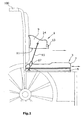
- a first embodiment of a positioning device 1 according to the invention for positioning a physically disabled person in a sitting position is shown schematically in a side view.
- the positioning device 1 is placed on a seat surface of a wheelchair 100.
- Fig. 1 the physically handicapped person not shown.
- the positioning device 1 consists of a seat 3 with a base 5 and a relative to the base 5 slidable seat surface 7.
- the base 5 may for example be attached to the seat surface of the wheelchair.
- the seat 7 is, for example, with the help of in Fig. 1 not shown rails guided to the base 5 and is displaceable in the seat direction or against the seat direction.
- the seating direction is in Fig. 1 indicated by an arrow.
- the positioning device 1 further comprises a dimensionally stable positioning sleeve 9, which is shaped such that the positioning sleeve 9 is positively applied to the pelvic area of a physically disabled person.
- the positioning sleeve 9 bearing surfaces 11, with which the Positioning sleeve 11 is supported in the applied state on the iliac crest of the person.
- the positioning sleeve 9 has a closure 13.
- the positioning sleeve 9 can be made of an elastic material, wherein the shape stability of the positioning sleeve can be produced by the closure.
- the positioning sleeve 9 can thus be applied advantageously by elastic bending on the pelvic region of the person and then brought into a dimensionally stable state by closing the closure.
- traction means 15 are arranged, which connect the positioning sleeve 9 with the base 5 of the seat 3.
- the traction means 15 are connected via articulation points 14 with the positioning sleeve 9 and each have actuators 17, via which by means of the traction means a tensile force can be exerted on the positioning sleeve. Because the traction means are fastened laterally on the positioning collar and on the outer end of the base 5, counter to the seating direction, the traction means 15 can exert a force on the positioning collar in the direction of the seat surface 7 and in a direction opposite to the seating direction.
- the seat surface 7 may first be moved relative to the base 5 in the seat direction, so that the seat 7 is pulled in the positioning of the physically disabled person by the tensile force in the direction opposite to the sitting direction and thus in the direction of the seat back of the wheelchair. This supports the positioning of the physically handicapped person in the sitting position.
- the positive engagement of the positioning sleeve 9 on the pelvic region of the person as well as the dimensionally stable design of the positioning collar 9 allow the tensile force to be transferred to the person's iliac crest and prevent the pelvis from twisting.
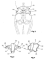
- FIG. 2 An embodiment of a positioning collar 9 for a positioning device according to the invention is shown schematically in the state applied to the body of a physically handicapped person.
- the positioning sleeve 9 has a spine 21, which rests in the applied state on the back of the person. Via a closure 13, the positioning sleeve 9 is closed in the front region, so that a dimensional stability of the positioning sleeve 9 is given.
- the positioning sleeve 9 has contact surfaces 11 which are supported on the person's iliac crest.
- two abutting points 14 are arranged, to which in Fig. 2 Traction means 2, not shown, can be fastened. As a result, a tensile force can be exerted on the positioning collar 9, which presses the person into the sitting position.
- the positioning sleeve 9 of a positioning device is shown.
- the positioning sleeve is largely formed of a tubular construction, wherein the tube construction has a return system 21.
- the tube construction is bent such that the positioning sleeve 9 is adapted to the body of the physically handicapped person.
- the positioning collar has a closure 13. Since the tube construction has a low flexibility, articulated connections 19 are arranged, so that after opening the closure 13, the pipe construction can be partially swung open, so that a purchase and removal of the positioning sleeve 9 in a simple manner possible.
- articulation points 14 are arranged, to which the traction means, which in 3 and 4 not shown, can be articulated.
- the pipe construction has in the lower area bearing surfaces 11, which are supported in the applied state on the iliac crest of the physically disabled person.
- the traction means may be, for example, tensioning straps, tensioning straps, tensioning straps or tie rods.
- the tie rods may be formed, for example, as threaded rods, which can serve as an actuator screw threaded sleeve with opposite threads.
- straps or straps can serve as a belt tensioner actuator.
- the seat may have a motor, with which the seat is driven to move.
- the engine may be configured, for example, as an electric motor. In this way, the positioning of the physically handicapped person is possible in a particularly simple manner, since the motor supports the positioning of the physically handicapped person by moving the seat.
- the engine of the seat can also drive, for example, the actuating device of the traction means, so that they are actuated automatically. Of course, a separate drive for the actuators of the traction means may be provided.
- the actuating devices of the traction means can also be formed or driven by a mechanical drive, which is coupled to the seat surface of the seat and is actuated by the displacement of the seat surface.
- the actuating device may be formed by a coil, which is rotated by the displacement of the seat and the traction means rolls up. At the base then the traction means can run, for example, to a deflection roller.
- a physically handicapped person can now be positioned as follows with the positioning device according to the invention.
- the positioning cuff is placed in the pelvic area of the disabled person, so that the bearing surfaces are supported on the iliac crest of the physically disabled person and the backrest abuts the back of the person.
- the closure of the positioning collar is now closed, so that a dimensional stability of the positioning sleeve is given.
- the physically handicapped person is now seated in the seating direction of the seat. Between the articulation points of a positioning sleeve and the base of the seat traction means are now attached. With the aid of the actuating device of the traction means, a tensile force is applied to the positioning sleeve in the direction of the seat surface and in a direction opposite to the seat direction. As a result, the physically handicapped person is pulled into the sitting position, at the same time the seat is pulled against the sitting direction. It can be provided that the seat engages in a first position in which the sitting position is not quite reached. This has the advantage that in spasticians who have a strong spasm of the pelvic muscles, the person can initially be positioned in this idea until the muscles have relaxed accordingly or relaxed. Afterwards the person can be pulled into the final sitting position. Ideally, the body of the physically handicapped person in the sitting position between the trunk and thigh an angle between 80 ° and 100 °, preferably ⁇ 90 °.
- the positioning device 1 only stabilizes the pelvis of the physically handicapped person. It has been found that, especially in spastic patients, who often suffer from pelvic stiffening, positioning in the sitting position and stabilization of the pelvis lead to improved trunk control and better control of the entire musculoskeletal system. Surprisingly, in the case of a positioning of a spasticizer with the positioning device according to the invention, the swallowing behavior of the spastiker already improves after a short time, so that a reduction of the saliva outflow can be achieved. It has also been found that positioned with the help of the positioning device, spastic disabled persons have a mentally better reception.
Landscapes
- Health & Medical Sciences (AREA)
- Life Sciences & Earth Sciences (AREA)
- Veterinary Medicine (AREA)
- Public Health (AREA)
- General Health & Medical Sciences (AREA)
- Animal Behavior & Ethology (AREA)
- Engineering & Computer Science (AREA)
- Vascular Medicine (AREA)
- Heart & Thoracic Surgery (AREA)
- Biomedical Technology (AREA)
- Orthopedic Medicine & Surgery (AREA)
- Nursing (AREA)
- Chair Legs, Seat Parts, And Backrests (AREA)
- Orthopedics, Nursing, And Contraception (AREA)
Description
- Die vorliegende Erfindung betrifft eine Positionierungsvorrichtung und ein Verfahren zum Positionieren von körperbehinderten Personen in eine Sitzstellung.
- Bei körperbehinderten Personen mit Muskelerkrankungen oder spastischen Lähmungen besteht häufig das Problem, dass aufgrund von Muskelversteifungen oder Muskelverkrampfungen ein Positionieren der Personen in eine Sitzstellung nur mit sehr großem Aufwand möglich ist. Zumeist werden die Personen von Betreuern oder Pflegern unter großem Kraftaufwand in die entsprechende Sitzstellung gedrückt.
- Diese Prozedur ist sowohl für die körperbehinderte Person als auch für den Pfleger, bzw. Betreuer unbequem, zumal die körperbehinderte Person häufig lange in einer Stellung gehalten werden muss, bis sich die Muskeln entkrampfen bzw. sich entspannen.
- In einer Sitzposition haben derartige körperbehinderte Personen häufig eine Fehlhaltung, die zu Wirbelsäulenschäden führen kann. Aus diesem Grund schlägt die
DE 10304785 A1 einen körperangepassten, offenen Stützring aus elastischem Material vor, der seitliche Anlegezungen sowie eine sich gegen das Schambein abstützende Schambeinanlage aufweist. Der Stützring ist mit mehreren Befestigungsmitteln an der Sitzlehne und der Sitzfläche eines Sitzes, beispielsweise an einem Rollstuhl, befestigt. Die vorgeschlagene Vorrichtung ermöglicht lediglich eine stützende Wirkung in der Sitzposition, um die Wirbelsäulenfehlhaltung zu vermeiden. - Die körperbehinderte Person muss jedoch weiterhin von den Betreuern oder Pflegern in die entsprechende Sitzposition gedrückt werden. Lediglich bei einem Ausführungsbeispiel, bei dem ein verschiebbares Sitzuntergestell vorgesehen ist, kann die Positionierung der körperbehinderten Person mit Hilfe des Sitzuntergestells im geringen Maße unterstützt werden. Aufgrund der offenen und elastischen Ausgestaltung des Stützrings ist eine Positionierung der körperbehinderten Person über den Stützring nicht möglich, da bei dem Aufbringen von Kräften auf den Stützring dieser sich aufbiegen würde, sodass die Person aus dem Stützring herausrutschen kann. Darüber hinaus besteht die Gefahr, dass beim Positionieren der körperbehinderten Person über die vorgeschlagene Vorrichtung Verletzungen durch die Anlegezungen oder die Schambeinanlage entstehen können. Aufgrund der Schambeinanlage ist darüber hinaus eine vorteilhafte Sitzposition nicht oder nur eingeschränkt möglich.
- Um die sowohl für Betreuer, bzw. Pfleger als auch die körperbehinderte Person unbequeme Positionierungsprozedur zu vereinfachen, wäre daher eine Vorrichtung zur Positionierung der körperbehinderten Personen wünschenswert.
- Es ist daher die Aufgabe der vorliegenden Erfindung, eine Positionierungsvorrichtung sowie ein Verfahren zum Positionieren einer körperbehinderten Person in eine Sitzstellung bereitzustellen, die das Positionieren der körperbehinderten Person auf eine einfache Art und Weise ermöglicht ohne dass ein Betreuer oder Pfleger die körperbehinderte Person in aufwändiger Art und Weise in die Sitzposition drücken muss.
- Zur Lösung der Aufgabe, dienen die Merkmale des Anspruchs 1 sowie das Verfahren nach Anspruch 12.
- Erfindungsgemäß ist vorgesehen, dass eine Positionierungsvorrichtung zum Positionieren einer körperbehinderten Person in eine Sitzstellung, vorzugsweise in einem Rollstuhl, einen Sitz mit einer Basis und einer gegenüber der Basis verschiebbaren Sitzfläche aufweist. Ferner ist eine formstabile Positionierungsmanschette vorgesehen, die am Beckenbereich der Person formschlüssig anlegbar ist und sich im angelegten Zustand mit Auflageflächen auf dem Beckenkamm der Person abstützt. An der Positionierungsmanschette sind Zugmittel vorgesehen, die die Positionierungsmanschette mit der Basis des Sitzes verbinden, wobei die Zugmittel jeweils in einem Seitenbereich der Positionierungsmanschette befestigt sind und eine Betätigungseinrichtung aufweisen. Bei Betätigung der Zugmittel können die Zugmittel auf die Positionierungsmanschette eine Zugkraft in Richtung der Sitzfläche und in einer Richtung entgegen der Sitzrichtung ausüben, wodurch die Person in die Sitzstellung ziehbar ist.
- Die erfindungsgemäße Positionierungsvorrichtung hat den Vorteil, dass mit Hilfe der Positionierungsmanschette die körperbehinderte Person in die Sitzstellung ziehbar ist. Dabei ist es nicht notwendig, dass ein Pfleger oder Betreuer die körperbehinderte Person in aufwändiger Art und Weise drückt. Durch das Vorsehen einer formstabilen Positionierungsmanschette wird vermieden, dass während des Positionierungsvorgangs die körperbehinderte Person aus der Manschette herausrutschen kann. Darüber hinaus ermöglicht die erfindungsgemäße Positionierungsvorrichtung, dass die körperbehinderte Person zunächst in eine Stellung, die annähernd der Sitzstellungen ist, positioniert werden kann und mit Hilfe der Positionierungsmanschette in dieser Stellung gehalten werden kann. In dieser Stellung können sich die Muskeln der körperbehinderten Person entspannen bzw. entkrampfen, sodass danach ein Verbringen der körperbehinderten Person in die endgültige Sitzstellung möglich ist. Durch das Vorsehen einer gegenüber einer Basis verschiebbaren Sitzfläche und das Verbinden der Positionierungsmanschette mit der Basis der Sitzfläche, kann mit Hilfe der Zugmittel die verschiebbare Sitzfläche beim Positionieren der körperbehinderten Personen verschoben werden, sodass die verschiebbare Sitzfläche den Positionierungsvorgang unterstützt und darüber hinaus einen, für die körperbehinderte Person bequemeren Positionierungsvorgang ermöglicht.
- Die erfindungsgemäße Positionierungsvorrichtung kann sowohl mit einem Rollstuhl als auch mit einem herkömmlichen Stuhl verwendet werden oder Teil von diesem sein. Mit Hilfe der Zugmittel kann die Person zu der Sitzfläche und in Richtung einer Sitzlehne gezogen werden. Unter Basis des Sitzes im Rahmen der Erfindung wird ein gegenüber der Sitzfläche ortsfester Teil des Sitzes verstanden. Bei einem Ausführungsbeispiel, bei dem der Sitz Teil eines Stuhl oder Rollstuhls ist, kann somit die Basis auch ein Teil des Stuhls oder Rollstuhls sein.
- Vorzugsweise ist vorgesehen, dass die Positionierungsmanschette geschlossen ist, wobei die Positionierungsmanschette beispielsweise einen Verschluss aufweisen kann. Durch die geschlossene Positionierungsmanschette kann beispielsweise die Formstabilität der Positionierungsmanschette gewährleistet werden, selbst dann, wenn die Positionierungsmanschette aus einem eher elastischen Material hergestellt ist. Darüber hinaus ermöglicht der Verschluss, dass die Positionierungsmanschette in vorteilhafter Weise am Beckenbereich der Person formschlüssig anlegbar ist.
- In einem Ausführungsbeispiel der Erfindung ist vorgesehen, dass zwei Zugmittel vorgesehen sind, wobei jeweils ein Zugmittel an einer Seite der Positionierungsmanschette angeordnet ist. Durch das Vorsehen von jeweils einem Zugmittel an einer Seite der Positionierungsmanschette kann die körperbehinderte Person gleichmäßig in die Sitzstellung gezogen werden, wobei gleichzeitig gewährleistet wird, dass die Zugmittel gut zugänglich sind und somit auf einfache Art und Weise betätigbar sind.
- Es kann vorgesehen sein, dass die Positionierungsmanschette mehrteilig ist, wobei die mehreren Teile der Positionierungsmanschette durch Steck- oder Gelenkverbindungen miteinander verbindbar, bzw. verbunden sind. Durch das Vorsehen einer derartigen Positionierungsmanschette ist die Bereitstellung einer besonders formstabilen Positionierungsmanschette auf einfache Art und Weise möglich, wobei gleichzeitig gewährleistet wird, dass die Positionierungsmanschette auf einfache Art und Weise am Beckenbereich der Person formschlüssig anlegbar ist.
- Dabei kann vorgesehen sein, dass die Positionierungsmanschette aus mehreren Rohrteilen besteht. Dadurch ist es möglich, die Positionierungsmanschette auf eine einfachen Art und Weise und kostengünstig herzustellen.
- Nach einem Ausführungsbeispiel ist vorgesehen, dass die Positionierungsvorrichtung eine Rückenanlage aufweist. Durch die Rückenanlage wird ermöglicht, dass die Positionierungsmanschette im angelegten Zustand bequem für die Person tragbar ist, wobei gleichzeitig verhindert werden kann, dass sich die Positionierungsmanschette beispielsweise verdrehen oder verkannten kann.
- Die Zugmittel können Spannbänder, Spannriemen, Spanngurte oder Zugstangen sein.
- Nach einem Ausführungsbeispiel der Erfindung kann vorgesehen sein, dass die Sitzfläche an der Basis arretierbar ist, vorzugsweise in zwei Positionen. Dadurch wird ermöglicht, dass die körperbehinderte Person beispielsweise zunächst in eine erste Körperstellung gezogen wird, in der die Sitzfläche arretiert wird. Nach einem Entspannen bzw. Entkrampfen der Muskulatur kann die Person danach in die endgültige Sitzstellung gezogen werden, in der die Sitzfläche dann wiederum arretiert wird.
- In einer vorteilhaften Ausgestaltung der Erfindung kann vorgesehen sein, dass der Sitz einen Motor aufweist, über den die Sitzfläche zum Verschieben antreibbar ist, wobei der Motor vorzugsweise ein Elektromotor ist. Durch das Vorsehen eines Motors kann das Positionieren der körperbehinderten Person unterstützt werden, sodass über die Zugmittel noch eine geringere Zugkraft ausgeübt werden muss. Die Verwendung eines Elektromotors ist dabei besonders vorteilhaft, da beispielsweise der Elektromotor über eine Batterie versorgt werden kann. Bei der Verwendung der erfindungsgemäßen Positionierungsvorrichtung in einem elektrischen Rollstuhl kann beispielsweise der Elektromotor des Sitzes über die Rollstuhlbatterie versorgt werden.
- Die Erfindung sieht ferner die Verwendung einer erfindungsgemäßen Positionierungsvorrichtung zum Positionieren von körperbehinderten Personen in eine Sitzstellung, vorzugsweise in einem Rollstuhl vor. Dabei kann vorgesehen sein, dass in der Sitzstellung der Körper der körperbehinderten Person zwischen Rumpf und Oberschenkel ein Winkel zwischen 80 ° und 100 °, vorzugsweise zwischen 85 ° und 90 ° aufweist.
- Die Erfindung sieht ferner ein Verfahren zum Positionieren von körperbehinderten Personen in eine Sitzstellung, vorzugsweise in einem Rollstuhl vor mit folgenden Schritten:
- formschlüssiges Anlegen einer formstabilen Positionierungsmanschette am Beckenbereich der Person, derart, dass sich die Positionierungsmanschette mit Auflageflächen auf dem Beckenkamm der Person abstützt,
- Setzen der Person auf eine verschiebbare Sitzfläche,
- Ziehen der Positionierungsmanschette in Richtung der Sitzfläche und in eine Richtung entgegen der Sitzrichtung und gleichzeitiges Verschieben der Sitzfläche in Richtung entgegen der Sitzrichtung derart, dass die Person in die Sitzstellung ziehbar ist.
- Dabei kann vorgesehen sein, dass in der Sitzstellung der Körper der Person zwischen Rumpf und Oberschenkel einen Winkel zwischen 80 ° und 100 °, vorzugsweise zwischen 85 ° und 90 ° aufweist.
- Bei dem erfindungsgemäßen Verfahren kann eine erfindungsgemäße Positionierungsvorrichtung vorgesehen sein.
- Im Folgenden wird unter Bezugnahme auf die nachfolgenden Figuren die Erfindung näher erläutert. Es zeigen:
- Fig. 1
- eine schematische Seitenansicht einer erfindungsgemäßen Positionierungsvorrichtung in einem Rollstuhl
- Fig. 2
- eine schematische Draufsicht der Positionierungsmanschette einer erfindungsgemäßen Positionierungsvorrichtung sowie
- Fign. 3 u. 4
- Ansichten eines zweiten Ausführungsbeispiels einer Positionierungsmanschette einer erfindungsgemäßen Positionierungsvorrichtung.
- In
Fig.1 ist ein erstes Ausführungsbeispiel einer erfindungsgemäßen Positionierungsvorrichtung 1 zum Positionieren einer körperbehinderten Person in einer Sitzstellung schematisch in einer Seitenansicht dargestellt. Die Positionierungsvorrichtung 1 ist auf eine Sitzfläche eines Rollstuhls 100 aufgesetzt. Der Einfachheit halber ist inFig. 1 die körperbehinderte Person nicht dargestellt. - Die Positionierungsvorrichtung 1 besteht aus einem Sitz 3 mit einer Basis 5 und einer gegenüber der Basis 5 verschiebbaren Sitzfläche 7. Die Basis 5 kann beispielsweise an der Sitzfläche des Rollstuhls befestigt werden.
- Die Sitzfläche 7 ist beispielsweise mit Hilfe von in
Fig. 1 nicht dargestellten Schienen an die Basis 5 geführt und ist in Sitzrichtung bzw. entgegen der Sitzrichtung verschiebbar. Die Sitzrichtung ist inFig. 1 durch einen Pfeil angedeutet. - Die Positionierungsvorrichtung 1 weist ferner eine formstabile Positionierungsmanschette 9 auf, die derart geformt ist, dass die Positionierungsmanschette 9 am Beckenbereich einer körperbehinderten Person formschlüssig anlegbar ist. Im unteren Bereich weist die Positionierungsmanschette 9 Auflageflächen 11 auf, mit der sich die Positionierungsmanschette 11 im angelegten Zustand auf dem Beckenkamm der Person abstützt.
- Im vorderen Bereich weist die Positionierungsmanschette 9 einen Verschluss 13 auf. Auf diese Weise kann gewährleistet sein, dass die Positionierungsmanschette 9 aus einem elastischen Material gefertigt sein kann, wobei durch den Verschluss die Formstabilität der Positionierungsmanschette hergestellt werden kann. Die Positionierungsmanschette 9 kann somit in vorteilhafter Weise durch elastische Verbiegung an dem Beckenbereich der Person angelegt werden und anschließend durch Verschließen des Verschlusses in einen formstabilen Zustand gebracht werden.
- In einem Seitenbereich der Positionierungsmanschette 9 sind Zugmittel 15 angeordnet, die die Positionierungsmanschette 9 mit der Basis 5 des Sitzes 3 verbinden. Die Zugmittel 15 sind über Anlenkpunkte 14 mit der Positionierungsmanschette 9 verbunden und weisen jeweils Betätigungseinrichtungen 17 auf, über die mit Hilfe der Zugmittel eine Zugkraft auf die Positionierungsmanschette ausgeübt werden kann. Dadurch dass die Zugmittel seitlich an der Positionierungsmanschette sowie am, entgegen der Sitzrichtung, äußeren Ende der Basis 5 befestigt sind, können die Zugmittel 15 auf die Positionierungsmanschette eine Kraft in Richtung der Sitzfläche 7 und in eine Richtung entgegen der Sitzrichtung ausüben. Dadurch kann eine körperbehinderte Person, an der die Positionierungsmanschette angelegt ist, mit Hilfe der Zugmittel in eine Sitzstellung gezogen werden, in dem die Zugkraft über die Positionierungsmanschette 9 auf den Beckenkamm der Person und somit auf die Person übertragen wird, sodass die Person in die Sitzstellung gedrückt wird.
- Dabei kann die Sitzfläche 7 zunächst gegenüber der Basis 5 in Sitzrichtung verschoben sein, sodass die Sitzfläche 7 bei dem Positionieren der körperbehinderten Person durch die Zugkraft in die Richtung entgegen der Sitzrichtung und somit in Richtung der Sitzlehne des Rollstuhls gezogen wird. Dadurch wird das Positionieren der körperbehinderten Person in die Sitzstellung unterstützt.
- Die formschlüssige Anlage der Positionierungsmanschette 9 am Beckenbereich der Person sowie die formstabile Ausgestaltung der Positionierungsmanschette 9 ermöglichen, dass die Zugkraft auf den Beckenkamm der Person übertragen und ein Verdrehen des Beckens verhindert wird.
- In
Fig. 2 ist ein Ausführungsbeispiel einer Positionierungsmanschette 9 für eine erfindungsgemäße Positionierungsvorrichtung schematisch im an den Körper einer körperbehinderten Person angelegten Zustand gezeigt. - Die Positionierungsmanschette 9 weist eine Rückenanlage 21 auf, die im angelegten Zustand an dem Rücken der Person anliegt. Über einen Verschluss 13 ist die Positionierungsmanschette 9 im vorderen Bereich verschlossen, sodass eine Formstabilität der Positionierungsmanschette 9 gegeben ist.
- Im unteren Bereich weist die Positionierungsmanschette 9 Auflageflächen 11 auf, die sich auf dem Beckenkamm der Person abstützen. Im seitlichen Bereich der Positionierungsmanschette sind zwei anliegende Punkte 14 angeordnet, an die in
Fig. 2 nicht dargestellte Zugmittel 2 befestigt werden können. Dadurch kann auf die Positionierungsmanschette 9 eine Zugkraft ausgeübt werden, die die Person in die Sitzstellung drückt. - In
Fig. 3 und 4 ist ein zweites Ausführungsbeispiel einer Positionierungsmanschette 9 einer erfindungsgemäßen Positionierungsvorrichtung gezeigt. In dem inFig. 4 dargestellten Ausführungsbeispiel ist die Positionierungsmanschette weitestgehend aus einer Rohrkonstruktion gebildet, wobei die Rohrkonstruktion eine Rückanlage 21 aufweist. Die Rohrkonstruktion ist derart gebogen, dass die Positionierungsmanschette 9 an dem Körper der körperbehinderten Person angepasst ist. Im vorderen Bereich weist die Positionierungsmanschette einen Verschluss 13 auf. Da die Rohrkonstruktion eine geringe Flexibilität aufweist, sind Gelenkverbindungen 19 angeordnet, sodass nach Öffnen des Verschlusses 13 die Rohrkonstruktion teilweise aufgeschwenkt werden kann, sodass ein An- und Ablegen der Positionierungsmanschette 9 auf einfache Art und Weise möglich ist. Im Seitenbereich der Positionierungsmanschette 9 sind Anlenkpunkte 14 angeordnet, an die Zugmittel, die inFig. 3 und 4 nicht dargestellt sind, angelenkt werden können. - Die Rohrkonstruktion weist im unteren Bereich Auflageflächen 11 auf, die sich im angelegten Zustand auf dem Beckenkamm der körperbehinderten Person abstützen.
- Bei einer erfindungsgemäßen Positionierungsvorrichtung können die Zugmittel beispielsweise Spannbänder, Spannriemen, Spanngurte oder Zugstangen sein. Die Zugstangen können Beispielsweise als Gewindestangen ausgebildet sein, wobei als Betätigungsvorrichtung eine Schraubmuffe mit gegenläufigen Gewinde dienen kann. Bei Spannbändern oder Spanngurten kann als Betätigungsvorrichtung ein Gurtspanner dienen.
- Der Sitz kann einen Motor aufweisen, mit dem die Sitzfläche zum Verschieben antreibbar ist. Der Motor kann beispielsweise als Elektromotor ausgestaltet sein. Auf diese Weise ist die Positionierung der körperbehinderten Person auf besonders einfache Art und Weise möglich, da der Motor durch das Verschieben der Sitzfläche das Positionieren der körperbehinderten Person unterstützt. Der Motor des Sitzes kann auch beispielsweise die Betätigungsvorrichtung der Zugmittel antreiben, so dass diese automatisch betätigt werden. Selbstverständlich kann auch ein separater Antrieb für die Betätigungsvorrichtungen der Zugmittel vorgesehen sein. Die Betätigungsvorrichtungen der Zugmittel können auch durch einen mechanischen Antrieb, der mit der Sitzfläche des Sitzes gekoppelt ist und durch das Verschieben der Sitzfläche betätigt wird, gebildet sein oder angetrieben werden. Beispielsweise kann die Betätigungsvorrichtung durch eine Spule gebildet sein, die durch das Verschieben der Sitzfläche gedreht wird und das Zugmittel aufrollt. An der Basis kann dann das Zugmittel beispielsweise um eine Umlenkrolle laufen.
- Eine körperbehinderte Person kann nun folgendermaßen mit der erfindungsgemäßen Positionierungsvorrichtung positioniert werden. Zunächst wird die Positionierungsmanschette im Beckenbereich der körperbehinderten Person angelegt, sodass die Auflageflächen sich an dem Beckenkamm der körperbehinderten Person abstützen und die Rückenanlage am Rücken der Person anliegt. Der Verschluss der Positionierungsmanschette wird nun verschlossen, sodass eine Formstabilität der Positionierungsmanschette gegeben ist. Durch die entsprechende Anpassung der Positionierungsmanschette an den Körper der körperbehinderten Person ist nunmehr ein Verdrehen der Positionierungsmanschette nicht mehr möglich.
- Die körperbehinderte Person wird nun auf die in Sitzrichtung verschobene Sitzfläche des Sitzes gesetzt. Zwischen den Anlenkpunkten einer Positionierungsmanschette und der Basis des Sitzes werden nun Zugmittel angebracht. Mit Hilfe der Betätigungsvorrichtung der Zugmittel wird eine Zugkraft auf die Positionierungsmanschette in Richtung der Sitzfläche und in eine Richtung entgegen der Sitzrichtung aufgebracht. Dadurch wird die körperbehinderte Person in die Sitzstellung gezogen, wobei gleichzeitig die Sitzfläche entgegen der Sitzrichtung gezogen wird. Dabei kann vorgesehen sein, dass die Sitzfläche in einer ersten Position einrastet, in der die Sitzstellung noch nicht ganz erreicht ist. Dies hat den Vorteil, dass bei Spastikern, die eine starke Verkrampfung der Beckenmuskulatur haben, die Person zunächst in dieser Vorstellung positioniert werden kann, bis sich die Muskulatur entsprechend entspannt bzw. entkrampft hat. Danach kann die Person in die endgültige Sitzstellung gezogen werden. Idealerweise besitzt der Körper der körperbehinderten Person in der Sitzstellung zwischen Rumpf und Oberschenkel einen Winkel zwischen 80 ° und 100 °, vorzugsweise < 90 °.
- Es hat sich herausgestellt, dass das Positionieren einer körperbehinderten Person, insbesondere eines Spastikers, in eine Sitzstellung, bei der der Körper der Person zwischen Rumpf und Oberschenkel einen Winkel zwischen 85 °und 90 ° aufweist, das Verhalten der Person in positiver Weise beeinflusst wird.
- Die erfindungsgemäße Positionierungsvorrichtung 1 stabilisiert dabei lediglich das Becken der körperbehinderten Person. Es hat sich herausgestellt, dass insbesondere bei Spastikern, die häufig unter einer Beckenversteifung leiden, die Positionierung in der Sitzstellung sowie die Stabilisierung des Beckens zu einer verbesserten Rumpfkontrolle sowie einer besseren Kontrolle des gesamten Bewegungsapparates führen. Überraschender Weise verbessert sich bei einer Positionierung eines Spastikers mit der erfindungsgemäßen Positionierungsvorrichtung bereits nach kurzer Zeit das Schluckverhalten des Spastikers, sodass eine Verminderung des Speichelausflusses erreicht werden kann. Auch hat sich herausgestellt, dass mit Hilfe der Positionierungsvorrichtung positionierte, spastisch behinderte Personen eine geistig bessere Aufnahme besitzen.
Claims (13)
- Positionierungsvorrichtung (1) zum Positionieren einer körperbehinderten Person in eine Sitzstellung, vorzugsweise in einem Rollstuhl,- mit einem Sitz (3) mit einer Basis (5) und mit einer gegenüber der Basis (5) verschiebbaren Sitzfläche (7),- mit einer formstabilen Positionierungsmanschette (9), wobei die Positionierungsmanschette (9) am Beckenbereich der Person formschlüssig anlegbar ist und sich im angelegten Zustand mit Auflageflächen (11) auf dem Beckenkamm der Person abstützt,- mit Zugmitteln (15), die der Positionierungsmanschette (9) mit der Basis (5) des Sitzes (3) verbinden, wobei die Zugmittel (15) jeweils an einem Seitenbereich der Positionierungsmanschette (9) befestigt sind und eine Betätigungseinrichtung (17) aufweisen,- wobei die Zugmittel (15) bei Betätigung auf die Positionierungsmanschette (9) eine Zugkraft in Richtung der Sitzfläche (7) und in eine Richtung entgegen der Sitzrichtung ausüben, wodurch die Person in die Sitzstellung ziehbar ist.
- Positionierungsvorrichtung nach Anspruch 1, dadurch gekennzeichnet, dass die Positionierungsmanschette (9) geschlossen ist, wobei die Positionierungsmanschette (9) vorzugsweise einen Verschluss (13) aufweist.
- Positionierungsvorrichtung nach Anspruch 1 oder 2, dadurch gekennzeichnet, dass zwei Zugmittel (15) vorgesehen sind, wobei jeweils ein Zugmittel (15) an einer Seite der Positionierungsmanschette (9) angeordnet ist.
- Positionierungsvorrichtung nach einem der Ansprüche 1 bis 3, dadurch gekennzeichnet, dass die Positionierungsmanschette (9) mehrteilig ist, wobei die mehreren Teile der Positionierungsmanschette (9) durch Steck- oder Gelenkverbindungen (19) miteinander verbindbar bzw. verbunden sind.
- Positionierungsvorrichtung nach Anspruch 4, dadurch gekennzeichnet, dass die Positionierungsmanschette (9) aus mehreren Rohrteilen besteht.
- Positionierungsvorrichtung nach einem der Ansprüche 1 bis 5, dadurch gekennzeichnet, dass die Positionierungsvorrichtung (9) eine Rückenanlage (21) aufweist.
- Positionierungsvorrichtung nach einem der Ansprüche 1 bis 6, dadurch gekennzeichnet, dass die Zugmittel (15) Spannbänder, Spannriemen, Spanngurte oder Zugstangen sind.
- Positionierungsvorrichtung nach einem der Ansprüche 1 bis 7, dadurch gekennzeichnet, dass die Sitzfläche (7) an der Basis (5) arretierbar ist, vorzugsweise in mindestens zwei Positionen.
- Positionierungsvorrichtung nach einem der Ansprüche 1 bis 8, dadurch gekennzeichnet, dass der Sitz einen Motor aufweist, über den die Sitzfläche (7) zum Verschieben antreibbar ist, wobei der Motor vorzugsweise ein Elektromotor ist.
- Verwendung einer Positionierungsvorrichtung (1) nach einem der Ansprüche 1 bis 9 zum Positionieren von körperbehinderten Personen in eine Sitzstellung, vorzugsweise in einem Rollstuhl (10).
- Verwendung nach Anspruch 10, dadurch gekennzeichnet, dass in der Sitzstellung der Körper der Person zwischen Rumpf und Oberschenkeln einen Winkel zwischen 80° und 100°, vorzugsweise zwischen 85° und 90°, aufweist.
- Verfahren zur Positionierung von körperbehinderten Personen in eine Sitzstellung, vorzugsweise in einem Rollstuhl, gekennzeichnet durch folgende Schritte:- formschlüssiges Anlegen einer formstabilen Positionierungsmanschette (9) am Beckenbereich der Person, derart, dass sich die Positionierungsmanschette (9) mit Auflageflächen (11) auf dem Beckenkamm der Person abstützt- Setzen der Person auf eine verschiebbare Sitzfläche (7)- Ziehen der Positionierungsmanschette (9) in Richtung der Sitzfläche (7) und in eine Richtung entgegen der Sitzrichtung und gleichzeitiges Verschieben der Sitzfläche (7) in Richtung entgegen der Sitzrichtung, derart, dass die Person in die Sitzstellung ziehbar ist;wobei eine Positionierungsvorrichtung (1) nach einem der Ansprüche 1 bis 9 verwendet wird.
- Verfahren nach Anspruch 12, dadurch gekennzeichnet, dass in der Sitzstellung der Körper der Personen zwischen Rumpf und Oberschenkel einen Winkel zwischen 80° und 100°, vorzugsweise zwischen 85°und 90°, aufweist.
Applications Claiming Priority (2)
| Application Number | Priority Date | Filing Date | Title |
|---|---|---|---|
| DE102010009537A DE102010009537A1 (de) | 2010-02-26 | 2010-02-26 | Positionierungsvorrichtung und Verfahren zum Positionieren von körperbehinderten Personen in eine Sitzstellung |
| PCT/EP2011/051818 WO2011104113A1 (de) | 2010-02-26 | 2011-02-08 | Positionierungsvorrichtung und verfahren zum positionieren von körperbehinderten personen in eine sitzstellung |
Publications (2)
| Publication Number | Publication Date |
|---|---|
| EP2538899A1 EP2538899A1 (de) | 2013-01-02 |
| EP2538899B1 true EP2538899B1 (de) | 2014-06-18 |
Family
ID=43898831
Family Applications (1)
| Application Number | Title | Priority Date | Filing Date |
|---|---|---|---|
| EP11703213.6A Not-in-force EP2538899B1 (de) | 2010-02-26 | 2011-02-08 | Positionierungsvorrichtung und verfahren zum positionieren von körperbehinderten personen in eine sitzstellung |
Country Status (3)
| Country | Link |
|---|---|
| EP (1) | EP2538899B1 (de) |
| DE (2) | DE102010009537A1 (de) |
| WO (1) | WO2011104113A1 (de) |
Family Cites Families (6)
| Publication number | Priority date | Publication date | Assignee | Title |
|---|---|---|---|---|
| US6213558B1 (en) * | 1999-06-22 | 2001-04-10 | Beneficial Designs | Pelvic stabilization device |
| US6513824B2 (en) * | 2000-06-28 | 2003-02-04 | Steven C. DuBose | Combination lift mechanism and wheelchair |
| DE10304785A1 (de) | 2003-02-06 | 2004-08-26 | Volker Knoche | Vorrichtungen zur Vermeidung einer Wirbelsäulen-Fehlhaltung |
| EP1725132A2 (de) * | 2004-03-18 | 2006-11-29 | Bodypoint Designs, Inc. | Seitlicher schwenkanbau und schnelllöseanordnung für eine hüftstabilisierungsvorrichtung |
| US7097628B1 (en) * | 2004-07-14 | 2006-08-29 | Baune Robert D | Traction chair system |
| GB0602534D0 (en) * | 2006-02-09 | 2006-03-22 | James Leckey Design Ltd | A chair for a disabled person |
-
2010
- 2010-02-26 DE DE102010009537A patent/DE102010009537A1/de not_active Withdrawn
-
2011
- 2011-02-08 EP EP11703213.6A patent/EP2538899B1/de not_active Not-in-force
- 2011-02-08 DE DE202011110261U patent/DE202011110261U1/de not_active Expired - Lifetime
- 2011-02-08 WO PCT/EP2011/051818 patent/WO2011104113A1/de not_active Ceased
Also Published As
| Publication number | Publication date |
|---|---|
| WO2011104113A1 (de) | 2011-09-01 |
| DE102010009537A1 (de) | 2011-09-01 |
| EP2538899A1 (de) | 2013-01-02 |
| DE202011110261U1 (de) | 2013-04-02 |
Similar Documents
| Publication | Publication Date | Title |
|---|---|---|
| DE112018002470B4 (de) | Trainingsgerät zur durchführung einer gluteusbrückenbewegung | |
| EP1155672B1 (de) | Vorrichtung zur Positionierung einer auf einer Liegefläche eines Bettes liegenden, schwersbehinderten Person | |
| DE102006021789A1 (de) | Gelenkorthese | |
| EP1633450A2 (de) | Trainingsvorrichtung für die Beckenbodenmuskulatur | |
| WO2017220084A1 (de) | Handorthese | |
| DE102004008509B4 (de) | Vorrichtung zum aktiven Aufrichten des Oberkörpers einer Person | |
| EP2538899A1 (de) | Positionierungsvorrichtung und verfahren zum positionieren von körperbehinderten personen in eine sitzstellung | |
| DE102016111820B4 (de) | Handorthese | |
| DE102016116388B4 (de) | Handorthese | |
| DE102022107519A1 (de) | Verfahren und Orthese zum Dehnen einer unteren Gliedmaße | |
| EP2975973A1 (de) | Verfahren und vorrichtung zum herstellen einer stützvorrichtung | |
| EP2991608B1 (de) | Extensionsliegenvorrichtung zur dekompression der wirbelsäule und/oder zur dekompression von gelenken | |
| EP3369408B1 (de) | Aufrichtegeschirr zum aufrichten einer person, aufrichthilfe mit einer hebeeinrichtung und einem solchen aufrichtegeschirr sowie anordnung | |
| DE102016107281A1 (de) | Therapeutisches Übungsgerät | |
| DE102019115325B4 (de) | Medizintechnische Vorrichtung zur Krafteinwirkung auf das Becken des Lebewesens sowie Herstellungsverfahren | |
| DE2540941A1 (de) | Vorrichtung zum uebertragen von zugkraeften auf die menschliche wirbelsaeule oder zum uebertragen von zugkraeften auf gliedmassen bzw. extremitaeten des menschlichen koerpers | |
| EP3213733B1 (de) | Vorrichtung zur mobilisierung von wirbeln | |
| WO2024017756A1 (de) | Bandage oder orthese mit bauchstützfunktion | |
| DE19731358C2 (de) | Übungsgerät, insbesondere zur Eigenmobilisierung von Körpergelenken, vor allem von Schultergelenken | |
| DE102017213300B3 (de) | Orthesengelenkschiene mit aktiv bewegter Pelotte und Gelenkorthese | |
| DE8901730U1 (de) | Vorrichtung für die Knie- und Hüftgelenkmobilisierung | |
| AT7654U1 (de) | Trainingsvorrichtung | |
| DE29916423U1 (de) | Vorrichtung zur Wiederherstellung der Mundlippen- und Wangenmuskeln | |
| DE102021125144A1 (de) | Verbesserte externe Kopfapparatur zur Senkung des Tonus der Kaumuskulatur bei Patienten mit Bruxismus und/oder anderen craniomandibulären Dysfunktionen (CMD) | |
| WO2022156858A1 (de) | Gesässstütze zur wenigstens teilweisen entlastung des körpergewichts einer person sowie entlastungssystem umfassend eine derartige gesässstütze |
Legal Events
| Date | Code | Title | Description |
|---|---|---|---|
| PUAI | Public reference made under article 153(3) epc to a published international application that has entered the european phase |
Free format text: ORIGINAL CODE: 0009012 |
|
| 17P | Request for examination filed |
Effective date: 20120807 |
|
| AK | Designated contracting states |
Kind code of ref document: A1 Designated state(s): AL AT BE BG CH CY CZ DE DK EE ES FI FR GB GR HR HU IE IS IT LI LT LU LV MC MK MT NL NO PL PT RO RS SE SI SK SM TR |
|
| DAX | Request for extension of the european patent (deleted) | ||
| REG | Reference to a national code |
Ref country code: DE Ref legal event code: R079 Ref document number: 502011003449 Country of ref document: DE Free format text: PREVIOUS MAIN CLASS: A61F0005370000 Ipc: A61G0005100000 |
|
| RIC1 | Information provided on ipc code assigned before grant |
Ipc: A61G 5/10 20060101AFI20131126BHEP Ipc: A61F 5/37 20060101ALI20131126BHEP |
|
| GRAP | Despatch of communication of intention to grant a patent |
Free format text: ORIGINAL CODE: EPIDOSNIGR1 |
|
| INTG | Intention to grant announced |
Effective date: 20140115 |
|
| GRAS | Grant fee paid |
Free format text: ORIGINAL CODE: EPIDOSNIGR3 |
|
| GRAA | (expected) grant |
Free format text: ORIGINAL CODE: 0009210 |
|
| AK | Designated contracting states |
Kind code of ref document: B1 Designated state(s): AL AT BE BG CH CY CZ DE DK EE ES FI FR GB GR HR HU IE IS IT LI LT LU LV MC MK MT NL NO PL PT RO RS SE SI SK SM TR |
|
| REG | Reference to a national code |
Ref country code: GB Ref legal event code: FG4D Free format text: NOT ENGLISH |
|
| REG | Reference to a national code |
Ref country code: CH Ref legal event code: EP |
|
| REG | Reference to a national code |
Ref country code: AT Ref legal event code: REF Ref document number: 672915 Country of ref document: AT Kind code of ref document: T Effective date: 20140715 |
|
| REG | Reference to a national code |
Ref country code: IE Ref legal event code: FG4D Free format text: LANGUAGE OF EP DOCUMENT: GERMAN |
|
| REG | Reference to a national code |
Ref country code: DE Ref legal event code: R096 Ref document number: 502011003449 Country of ref document: DE Effective date: 20140731 |
|
| REG | Reference to a national code |
Ref country code: CH Ref legal event code: NV Representative=s name: ISLER AND PEDRAZZINI AG, CH |
|
| REG | Reference to a national code |
Ref country code: NL Ref legal event code: T3 |
|
| PG25 | Lapsed in a contracting state [announced via postgrant information from national office to epo] |
Ref country code: LT Free format text: LAPSE BECAUSE OF FAILURE TO SUBMIT A TRANSLATION OF THE DESCRIPTION OR TO PAY THE FEE WITHIN THE PRESCRIBED TIME-LIMIT Effective date: 20140618 Ref country code: GR Free format text: LAPSE BECAUSE OF FAILURE TO SUBMIT A TRANSLATION OF THE DESCRIPTION OR TO PAY THE FEE WITHIN THE PRESCRIBED TIME-LIMIT Effective date: 20140919 Ref country code: NO Free format text: LAPSE BECAUSE OF FAILURE TO SUBMIT A TRANSLATION OF THE DESCRIPTION OR TO PAY THE FEE WITHIN THE PRESCRIBED TIME-LIMIT Effective date: 20140918 Ref country code: FI Free format text: LAPSE BECAUSE OF FAILURE TO SUBMIT A TRANSLATION OF THE DESCRIPTION OR TO PAY THE FEE WITHIN THE PRESCRIBED TIME-LIMIT Effective date: 20140618 Ref country code: CY Free format text: LAPSE BECAUSE OF FAILURE TO SUBMIT A TRANSLATION OF THE DESCRIPTION OR TO PAY THE FEE WITHIN THE PRESCRIBED TIME-LIMIT Effective date: 20140618 |
|
| REG | Reference to a national code |
Ref country code: LT Ref legal event code: MG4D |
|
| PG25 | Lapsed in a contracting state [announced via postgrant information from national office to epo] |
Ref country code: HR Free format text: LAPSE BECAUSE OF FAILURE TO SUBMIT A TRANSLATION OF THE DESCRIPTION OR TO PAY THE FEE WITHIN THE PRESCRIBED TIME-LIMIT Effective date: 20140618 Ref country code: SE Free format text: LAPSE BECAUSE OF FAILURE TO SUBMIT A TRANSLATION OF THE DESCRIPTION OR TO PAY THE FEE WITHIN THE PRESCRIBED TIME-LIMIT Effective date: 20140618 Ref country code: RS Free format text: LAPSE BECAUSE OF FAILURE TO SUBMIT A TRANSLATION OF THE DESCRIPTION OR TO PAY THE FEE WITHIN THE PRESCRIBED TIME-LIMIT Effective date: 20140618 Ref country code: LV Free format text: LAPSE BECAUSE OF FAILURE TO SUBMIT A TRANSLATION OF THE DESCRIPTION OR TO PAY THE FEE WITHIN THE PRESCRIBED TIME-LIMIT Effective date: 20140618 |
|
| PG25 | Lapsed in a contracting state [announced via postgrant information from national office to epo] |
Ref country code: RO Free format text: LAPSE BECAUSE OF FAILURE TO SUBMIT A TRANSLATION OF THE DESCRIPTION OR TO PAY THE FEE WITHIN THE PRESCRIBED TIME-LIMIT Effective date: 20140618 Ref country code: PT Free format text: LAPSE BECAUSE OF FAILURE TO SUBMIT A TRANSLATION OF THE DESCRIPTION OR TO PAY THE FEE WITHIN THE PRESCRIBED TIME-LIMIT Effective date: 20141020 Ref country code: CZ Free format text: LAPSE BECAUSE OF FAILURE TO SUBMIT A TRANSLATION OF THE DESCRIPTION OR TO PAY THE FEE WITHIN THE PRESCRIBED TIME-LIMIT Effective date: 20140618 Ref country code: SK Free format text: LAPSE BECAUSE OF FAILURE TO SUBMIT A TRANSLATION OF THE DESCRIPTION OR TO PAY THE FEE WITHIN THE PRESCRIBED TIME-LIMIT Effective date: 20140618 Ref country code: EE Free format text: LAPSE BECAUSE OF FAILURE TO SUBMIT A TRANSLATION OF THE DESCRIPTION OR TO PAY THE FEE WITHIN THE PRESCRIBED TIME-LIMIT Effective date: 20140618 Ref country code: ES Free format text: LAPSE BECAUSE OF FAILURE TO SUBMIT A TRANSLATION OF THE DESCRIPTION OR TO PAY THE FEE WITHIN THE PRESCRIBED TIME-LIMIT Effective date: 20140618 |
|
| REG | Reference to a national code |
Ref country code: FR Ref legal event code: PLFP Year of fee payment: 5 |
|
| PG25 | Lapsed in a contracting state [announced via postgrant information from national office to epo] |
Ref country code: PL Free format text: LAPSE BECAUSE OF FAILURE TO SUBMIT A TRANSLATION OF THE DESCRIPTION OR TO PAY THE FEE WITHIN THE PRESCRIBED TIME-LIMIT Effective date: 20140618 Ref country code: IS Free format text: LAPSE BECAUSE OF FAILURE TO SUBMIT A TRANSLATION OF THE DESCRIPTION OR TO PAY THE FEE WITHIN THE PRESCRIBED TIME-LIMIT Effective date: 20141018 |
|
| REG | Reference to a national code |
Ref country code: DE Ref legal event code: R097 Ref document number: 502011003449 Country of ref document: DE |
|
| PLBE | No opposition filed within time limit |
Free format text: ORIGINAL CODE: 0009261 |
|
| STAA | Information on the status of an ep patent application or granted ep patent |
Free format text: STATUS: NO OPPOSITION FILED WITHIN TIME LIMIT |
|
| PG25 | Lapsed in a contracting state [announced via postgrant information from national office to epo] |
Ref country code: DK Free format text: LAPSE BECAUSE OF FAILURE TO SUBMIT A TRANSLATION OF THE DESCRIPTION OR TO PAY THE FEE WITHIN THE PRESCRIBED TIME-LIMIT Effective date: 20140618 Ref country code: IT Free format text: LAPSE BECAUSE OF FAILURE TO SUBMIT A TRANSLATION OF THE DESCRIPTION OR TO PAY THE FEE WITHIN THE PRESCRIBED TIME-LIMIT Effective date: 20140618 |
|
| 26N | No opposition filed |
Effective date: 20150319 |
|
| PG25 | Lapsed in a contracting state [announced via postgrant information from national office to epo] |
Ref country code: SI Free format text: LAPSE BECAUSE OF FAILURE TO SUBMIT A TRANSLATION OF THE DESCRIPTION OR TO PAY THE FEE WITHIN THE PRESCRIBED TIME-LIMIT Effective date: 20140618 |
|
| PG25 | Lapsed in a contracting state [announced via postgrant information from national office to epo] |
Ref country code: LU Free format text: LAPSE BECAUSE OF FAILURE TO SUBMIT A TRANSLATION OF THE DESCRIPTION OR TO PAY THE FEE WITHIN THE PRESCRIBED TIME-LIMIT Effective date: 20150208 |
|
| GBPC | Gb: european patent ceased through non-payment of renewal fee |
Effective date: 20150208 |
|
| PG25 | Lapsed in a contracting state [announced via postgrant information from national office to epo] |
Ref country code: MC Free format text: LAPSE BECAUSE OF FAILURE TO SUBMIT A TRANSLATION OF THE DESCRIPTION OR TO PAY THE FEE WITHIN THE PRESCRIBED TIME-LIMIT Effective date: 20140618 |
|
| REG | Reference to a national code |
Ref country code: IE Ref legal event code: MM4A |
|
| PG25 | Lapsed in a contracting state [announced via postgrant information from national office to epo] |
Ref country code: IE Free format text: LAPSE BECAUSE OF NON-PAYMENT OF DUE FEES Effective date: 20150208 Ref country code: GB Free format text: LAPSE BECAUSE OF NON-PAYMENT OF DUE FEES Effective date: 20150208 |
|
| REG | Reference to a national code |
Ref country code: FR Ref legal event code: PLFP Year of fee payment: 6 |
|
| PG25 | Lapsed in a contracting state [announced via postgrant information from national office to epo] |
Ref country code: MT Free format text: LAPSE BECAUSE OF FAILURE TO SUBMIT A TRANSLATION OF THE DESCRIPTION OR TO PAY THE FEE WITHIN THE PRESCRIBED TIME-LIMIT Effective date: 20140618 |
|
| REG | Reference to a national code |
Ref country code: FR Ref legal event code: PLFP Year of fee payment: 7 |
|
| PG25 | Lapsed in a contracting state [announced via postgrant information from national office to epo] |
Ref country code: HU Free format text: LAPSE BECAUSE OF FAILURE TO SUBMIT A TRANSLATION OF THE DESCRIPTION OR TO PAY THE FEE WITHIN THE PRESCRIBED TIME-LIMIT; INVALID AB INITIO Effective date: 20110208 Ref country code: SM Free format text: LAPSE BECAUSE OF FAILURE TO SUBMIT A TRANSLATION OF THE DESCRIPTION OR TO PAY THE FEE WITHIN THE PRESCRIBED TIME-LIMIT Effective date: 20140618 Ref country code: BG Free format text: LAPSE BECAUSE OF FAILURE TO SUBMIT A TRANSLATION OF THE DESCRIPTION OR TO PAY THE FEE WITHIN THE PRESCRIBED TIME-LIMIT Effective date: 20140618 |
|
| PG25 | Lapsed in a contracting state [announced via postgrant information from national office to epo] |
Ref country code: TR Free format text: LAPSE BECAUSE OF FAILURE TO SUBMIT A TRANSLATION OF THE DESCRIPTION OR TO PAY THE FEE WITHIN THE PRESCRIBED TIME-LIMIT Effective date: 20140618 |
|
| REG | Reference to a national code |
Ref country code: FR Ref legal event code: PLFP Year of fee payment: 8 |
|
| PG25 | Lapsed in a contracting state [announced via postgrant information from national office to epo] |
Ref country code: MK Free format text: LAPSE BECAUSE OF FAILURE TO SUBMIT A TRANSLATION OF THE DESCRIPTION OR TO PAY THE FEE WITHIN THE PRESCRIBED TIME-LIMIT Effective date: 20140618 |
|
| PG25 | Lapsed in a contracting state [announced via postgrant information from national office to epo] |
Ref country code: AL Free format text: LAPSE BECAUSE OF FAILURE TO SUBMIT A TRANSLATION OF THE DESCRIPTION OR TO PAY THE FEE WITHIN THE PRESCRIBED TIME-LIMIT Effective date: 20140618 |
|
| PGFP | Annual fee paid to national office [announced via postgrant information from national office to epo] |
Ref country code: FR Payment date: 20210317 Year of fee payment: 11 Ref country code: CH Payment date: 20210324 Year of fee payment: 11 Ref country code: NL Payment date: 20210319 Year of fee payment: 11 |
|
| PGFP | Annual fee paid to national office [announced via postgrant information from national office to epo] |
Ref country code: BE Payment date: 20210322 Year of fee payment: 11 Ref country code: AT Payment date: 20210318 Year of fee payment: 11 |
|
| PGFP | Annual fee paid to national office [announced via postgrant information from national office to epo] |
Ref country code: DE Payment date: 20220225 Year of fee payment: 12 |
|
| REG | Reference to a national code |
Ref country code: NL Ref legal event code: MM Effective date: 20220301 |
|
| REG | Reference to a national code |
Ref country code: CH Ref legal event code: PL |
|
| REG | Reference to a national code |
Ref country code: AT Ref legal event code: MM01 Ref document number: 672915 Country of ref document: AT Kind code of ref document: T Effective date: 20220208 |
|
| REG | Reference to a national code |
Ref country code: BE Ref legal event code: MM Effective date: 20220228 |
|
| PG25 | Lapsed in a contracting state [announced via postgrant information from national office to epo] |
Ref country code: AT Free format text: LAPSE BECAUSE OF NON-PAYMENT OF DUE FEES Effective date: 20220208 |
|
| PG25 | Lapsed in a contracting state [announced via postgrant information from national office to epo] |
Ref country code: NL Free format text: LAPSE BECAUSE OF NON-PAYMENT OF DUE FEES Effective date: 20220301 Ref country code: FR Free format text: LAPSE BECAUSE OF NON-PAYMENT OF DUE FEES Effective date: 20220228 |
|
| PG25 | Lapsed in a contracting state [announced via postgrant information from national office to epo] |
Ref country code: LI Free format text: LAPSE BECAUSE OF NON-PAYMENT OF DUE FEES Effective date: 20220228 Ref country code: CH Free format text: LAPSE BECAUSE OF NON-PAYMENT OF DUE FEES Effective date: 20220228 |
|
| PG25 | Lapsed in a contracting state [announced via postgrant information from national office to epo] |
Ref country code: BE Free format text: LAPSE BECAUSE OF NON-PAYMENT OF DUE FEES Effective date: 20220228 |
|
| REG | Reference to a national code |
Ref country code: DE Ref legal event code: R119 Ref document number: 502011003449 Country of ref document: DE |
|
| PG25 | Lapsed in a contracting state [announced via postgrant information from national office to epo] |
Ref country code: DE Free format text: LAPSE BECAUSE OF NON-PAYMENT OF DUE FEES Effective date: 20230901 |