EP2537983A1 - Dispositif de sécurité pour la signalisation routière - Google Patents
Dispositif de sécurité pour la signalisation routière Download PDFInfo
- Publication number
- EP2537983A1 EP2537983A1 EP12350003A EP12350003A EP2537983A1 EP 2537983 A1 EP2537983 A1 EP 2537983A1 EP 12350003 A EP12350003 A EP 12350003A EP 12350003 A EP12350003 A EP 12350003A EP 2537983 A1 EP2537983 A1 EP 2537983A1
- Authority
- EP
- European Patent Office
- Prior art keywords
- mast
- signaling
- plate
- signaling device
- post
- Prior art date
- Legal status (The legal status is an assumption and is not a legal conclusion. Google has not performed a legal analysis and makes no representation as to the accuracy of the status listed.)
- Granted
Links
Images

Classifications
-
- E—FIXED CONSTRUCTIONS
- E01—CONSTRUCTION OF ROADS, RAILWAYS, OR BRIDGES
- E01F—ADDITIONAL WORK, SUCH AS EQUIPPING ROADS OR THE CONSTRUCTION OF PLATFORMS, HELICOPTER LANDING STAGES, SIGNS, SNOW FENCES, OR THE LIKE
- E01F9/00—Arrangement of road signs or traffic signals; Arrangements for enforcing caution
- E01F9/60—Upright bodies, e.g. marker posts or bollards; Supports for road signs
- E01F9/623—Upright bodies, e.g. marker posts or bollards; Supports for road signs characterised by form or by structural features, e.g. for enabling displacement or deflection
- E01F9/631—Upright bodies, e.g. marker posts or bollards; Supports for road signs characterised by form or by structural features, e.g. for enabling displacement or deflection specially adapted for breaking, disengaging, collapsing or permanently deforming when deflected or displaced, e.g. by vehicle impact
Definitions
- the invention relates to a road signaling device.
- Road signage uses panels carried by a mast attached to the ground near the traffic lanes.
- the panel must be positioned at a height sufficient to be visible from a distance and therefore generally above 2 meters.
- the masts of the traffic signs located along the roads must in case of shock deform to absorb some of the kinetic energy or detach.
- the performance criteria of these poles are defined by standards. Standards are becoming more stringent and the means must be changed for both new panels and old ones.
- the majority of poles are substantially circular section because easier to produce and for easy orientation of the panel with fasteners clamp collar. This type of fixation is very widely used.
- poles generally globally cylindrical of revolution whose resistance control variable is the thickness.
- These are poles made of steel or spun aluminum. By acting on the thickness and the diameter, certain performances are obtained. But other types of poles are better.
- the resistance adjustment variable is the nature of the material and the construction of the pole which uses, for example, long fibers wound on a mandrel.
- the winding way and the thickness are adjustment parameters.
- poles polygonal section and it is the geometric structure of each face of the post that can control the deformation.
- These poles offer very good deformation capabilities but they are expensive.
- the base of these posts is fixed either on a metal plate which is then conventionally fixed on a solid concrete anchor or by an existing system of hooves.
- said post For the second types of posts, said post must be embedded in a deep concrete bed about 1 meter or more.
- the infrastructure is expensive. When damaged during a shock, the work requires replacing the concrete bed. It can not adapt to the existing concrete massifs
- the base of the polygon is fixed on a plate which comes to rest on a concrete mass. They are compatible with existing massifs.
- poles receive at their high end at least one sign.
- This sign must be oriented in a certain way with respect to the directions of the taxiways.
- This orientation does not pose a problem for the panels of the first and second types of posts because they have a circular section overall and all orientations are possible.
- the aim of the invention is to provide a remedy for these post substitution problems.
- This mast has a modified foot to make it more elastic during a shock.
- the mast that is formed from a tube is cut along 4 generators to form four legs that move downwards. These legs can be reported by welding. Because of their gradual spacing and the weight of the lamp, it is eventually necessary to connect by a grid of spacers these legs to increase the resistance to buckling (resistance to vertical load). In this document there is no mention of a problem of orientation of a panel on the top of the lamppost.
- the invention relates to a road signaling device comprising at least one sign posted at the top of a straight tubular signaling mast with controlled deformation comprising at the base a mounting plate intended to be anchored on a solid mass.
- this signaling mast being characterized in that the mast consists of two parts said low and high assembled by means of a so-called part separation, the said part low being the one having the required deformation capabilities and presenting as a post with a polygonal constant section whose faces are structured to deform, said lower part being connected to the plate by connecting means to controlled rupture and said upper part being constituted by at least one generally circular section tube having a cylindrical surface of rotation for the support of a fastening flange of the panel making it possible to orient it along an azimuth taken between 0 and 360 ° thus offering a greater number of possible orientations of the sign that those offered by the lower part.
- mast 1 security signaling having at its top a sign 2 which clings to a zone 3 said hooking.
- This signal mast is fixed to the ground, for example, by means of a plate 4 and bolts anchored in a solid 5 concrete.
- This tubular mast is designed for controlled deformation respecting a standard. He is right.
- FIG 1 a safety pole has been shown which complies with the European standard EN 12767.
- the panel is hung at the top and can take four orientations which are imposed by the four sides of the mast. This is an example of a mast but other masts appearing differently are commercially available.
- the mast 1 is composed of two parts 1A, 1B, a lower part 1A surmounted by an upper part, said lower part being constituted by a post with a polygonal section whose faces are structured to deform according to a programmed pattern and detaching a plate 4 and said upper portion being constituted by at least one generally circular section tube providing a greater number of orientations of the sign that those offered by the lower part.
- the two so-called low and high parts are assembled by means of a so-called separation part, the said lower part being the one having the required deformation capacities and presenting itself as a post with a polygonal constant section whose faces are structured to deform said lower part being connected to the plate by means of controlled-breaking connection means and said upper part being constituted by at least one generally circular section tube having a cylindrical surface of rotation for the support of a fastening flange the panel to orient it according to an azimuth taken between 0 and 360 ° thus providing a greater number of possible orientations of the sign that those offered by the lower part.
- the second part of the mast is a tube of the type used on the signaling posts of the prior art that it is desired to replace.
- the attachment surface is either a cylindrical surface of revolution with a constant radius or a cylindrical surface with multi-facets (non-constant radius).
- the cost is limited because the length used of the post with polygonal section and specific deformation meeting the European standard EN 12767 is reduced significantly.
- the length will be at least 1 meter and preferably between 1.5 and 2.5 meters (approximately between half and three quarters of the total height which is of the order of 3 to 6 meters).
- the performance of the overall post thus constructed is not affected because the impact of the cars is at a height of between 40 cm and 1.00 m, ie a point distant from the connection zone between the lower part and the part high.
- the lower part must however remain long enough to deform largely and thus absorb energy.
- a so-called plate-shaped separation part 6 or sheath on which separation piece will be mounted a piece of traditional mast is fixed on the end of the polygonal section pole .
- This separation piece is used as a connecting means between the two pieces of mast.
- An abutment or a separating plate at the base of the sheath assures that when a sliding assembly is used for the upper part, the sliding part does not penetrate the polygonal section which would affect the capabilities .
- the separating part and / or the base plate will be fixed by welding or screw.
- the use of screws makes it possible to calibrate the impact resistance of the lower part connection with the plate or the separating plate.
- the strength of the connection between the two parts must be sufficient to avoid the separation of the two sections during the fall of the mast.
- the masts built will comply with the European standard EN 12767.
- the separating part makes it possible to bind the two parts of the post but reduces the effects of one part on the other which could modify the behavior of the lower part.
- This plate locks the geometry of the top of the bottom part.
Landscapes
- Engineering & Computer Science (AREA)
- Architecture (AREA)
- Civil Engineering (AREA)
- Structural Engineering (AREA)
- Road Signs Or Road Markings (AREA)
Abstract
Description
- L'invention se rapporte à un dispositif de signalisation routière.
- Pour la signalisation routière, on utilise des panneaux portés par un mât fixé au sol à proximité des voies de circulations. Le panneau doit être positionné à une hauteur suffisante pour être visible de loin et donc généralement au dessus de 2 mètres.
- Les mâts des panneaux de circulation situés le long des routes doivent en cas de choc se déformer afin d'absorber une partie de l'énergie cinétique ou bien se détache. Les critères de performance de ces poteaux sont définis par des normes. Les normes sont de plus en plus contraignantes et il faut faire évoluer les moyens tant pour les nouveaux panneaux que pour les anciens.
- La majorité des poteaux sont à section sensiblement circulaire car plus simple à produire et permettant d'orienter facilement le panneau grâce à des fixations par bride collier. Ce type de fixation est très largement usité.
- Il y a donc les poteaux, généralement globalement cylindriques de révolution dont la variable de contrôle de la résistance est l'épaisseur. Ce sont des poteaux en acier ou en aluminium filé. En agissant sur l'épaisseur et le diamètre, on obtient certaines performances. Mais d'autres types de poteaux sont meilleurs.
- Ainsi, pour d'autres poteaux réalisés en matériau composite, la variable d'ajustement de résistance est la nature du matériau ainsi que la construction du poteau qui utilise, par exemple, des fibres longues enroulées sur un mandrin. La manière d'enrouler et l'épaisseur sont des paramètres d'ajustement.
- Il existe également, les poteaux à section polygonale, et c'est la structure géométrique de chaque face du poteau qui permet de contrôler la déformation. Ce sont des faces non pleines ( par exemple, la paroi comporte des lumières ou forme un treillis déformable).Ces poteaux offrent des capacités de déformation très bonnes mais ils sont couteux.
- Ces poteaux doivent être fixés au sol.
- Pour les poteaux du premier type en métal à section circulaire, la base de ces poteaux est fixée soit sur une platine métallique qui est alors fixée classiquement sur un massif béton d'ancrage soit par un système existant de sabots.
- Pour les seconds types de poteaux, ledit poteau doit être noyé dans un lit de béton profond d'environ 1 mètre ou plus. L'infrastructure est couteuse. Lorsqu'il est abimé lors d'un choc, les travaux nécessitent de remplacer le lit de béton. Il ne peut donc s'adapter sur les massifs en béton existants
- Pour les troisièmes poteaux, la base du polygone est fixée sur une platine qui vient prendre appui sur un massif en béton. Ils sont compatibles avec les massifs existants.
- Ces poteaux reçoivent en leur extrémité haute au moins un panneau de signalisation.
- Ce panneau de signalisation doit être orienté d'une certaine manière par rapport aux directions des voies de circulation.
- Cette orientation ne pose pas de problème pour les panneaux des premiers et deuxièmes types de poteaux car ils ont globalement une section circulaire et toutes les orientations sont possibles.
- Pour le poteau du troisième type, les systèmes connus viennent appliquer le panneau parallèlement à une des faces du poteau. Par conséquent, les orientations sont réduites au nombre de faces du poteau généralement à quatre faces ce qui est restreint. Compte tenu que l'ancrage au sol se fait en boulonnant les quatre coins du mât au moyen de quatre vis dont les têtes sont noyées dans le béton, l'orientation du massif doit être déterminée au préalable.
- Lors de l'installation du poteau, il faut alors définir l'orientation du massif en béton pour orienter correctement le poteau et son panneau de signalisation.
- Cette solution contraignante ne fonctionne pas pour le remplacement des poteaux existants pour lesquels le massif en béton a été coulé sans orientation particulière. Il faut alors couler un nouveau massif.
- Les collectivités locales souhaitent équiper leurs villes de ces poteaux spéciaux mais elles souhaiteraient le faire à moindre frais.
- L'invention vise à apporter un remède à ces problèmes de substitution de poteaux.
- Il est connu
FR 2183894 - A cet effet, l'invention se rapporte à dispositif de signalisation routière comprenant au moins un panneau de signalisation fixé au sommet d'un mât de signalisation tubulaire droit à déformation contrôlée comprenant à la base une platine de fixation destinée à être ancrée sur un massif en béton ce mât de signalisation étant caractérisé en ce que le mât se compose de deux parties dites basse et haute assemblées au moyen d'une pièce dite de séparation, la dite partie basse étant celle ayant les capacités de déformation exigée et se présentant comme un poteau à section constante polygonale dont les faces sont structurées pour se déformer , la dite partie basse étant reliée à la platine par des moyens de liaison à rupture contrôlée et la dite partie haute étant constituée par au moins un tube à section globalement circulaire présentant une surface cylindrique de rotation pour l'appui d'une bride de fixation du panneau permettant de l'orienter selon un azimut pris entre 0 et 360° offrant ainsi un plus grand nombre d'orientations possible du panneau de signalisation que celles offertes par la partie basse.
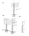
- L'invention sera bien comprise à l'aide de la description ci après faite à titre d'exemple non limitatif en regard du dessin qui représente :
-
FIG 1 : Mât de sécurité actuel -
FIG 2 :Panneau monté sur mâts selon l'invention -
FIG 3 Mât selon l'invention -
FIG 4 :Mât percuté - En se reportant au dessin, on voit un mât 1 de signalisation de sécurité présentant en son sommet un panneau 2 de signalisation qui s'accroche sur une zone 3 dite d'accrochage.
- Ce mât de signalisation est fixé au sol, par exemple, au moyen d'une platine 4 et de boulons ancrés dans un massif 5 en béton.
- Ce mât tubulaire est conçu pour une déformation contrôlée respectant une norme. Il est droit.
- En
figure 1 on a représenté un mât de sécurité respectant la norme Européenne EN 12767. Le panneau est accroché en haut et peut prendre quatre orientations qui sont imposées par les quatre faces du mât. Il s'agit d'un exemple de mât mais d'autres mâts se présentant différemment sont dans le commerce. - Avantageusement, le mât 1 se compose de deux parties 1A, 1B, une partie basse 1A surmontée d'une partie haute la dite partie basse étant constituée par un poteau à section polygonale dont les faces sont structurées pour se déformer selon un schéma programmé et se détacher d'une platine 4 et la dite partie haute étant constituée par au moins un tube à section globalement circulaire offrant un plus grand nombre d'orientations du panneau de signalisation que celles offertes par la partie basse.
- Ainsi les deux parties dites basse et haute sont assemblées au moyen d'une pièce dite de séparation, la dite partie basse étant celle ayant les capacités de déformation exigée et se présentant comme un poteau à section constante polygonale dont les faces sont structurées pour se déformer , la dite partie basse étant reliée à la platine par des moyens de liaison à rupture contrôlée et la dite partie haute étant constituée par au moins un tube à section globalement circulaire présentant une surface cylindrique de rotation pour l'appui d'une bride de fixation du panneau permettant de l'orienter selon un azimut pris entre 0 et 360° offrant ainsi un plus grand nombre d'orientations possible du panneau de signalisation que celles offertes par la partie basse.
- La deuxième partie du mât est un tube du type utilisé sur les poteaux de signalisation de l'art antérieur que l'on souhaite remplacer. La surface d'accrochage est soit une surface cylindrique de révolution à rayon constant soit une surface cylindrique à multi-facettes ( rayon non constant).
- Ainsi, en construisant un mât avec des composants différents, on apporte, grâce à la base spécifique, une sécurité lors d'un accident et une solution à l'orientation des panneaux de signalisation qui permet notamment de réutiliser des éléments de l'ancien dispositif de signalisation.
- Pour les poteaux à section polygonale, les orientations possible et simple sont limités au nombre de face du poteau (quatre ou six faces alors que pour un poteau à section circulaire, le nombre de position est infini.
- On limite le coût car la longueur utilisée du poteau à section polygonale et à déformation spécifique répondant a la norme Européenne EN 12767 est réduite significativement.
- La longueur sera d'au moins 1 mètre et de préférence entre 1.5 et 2.5 mètres (environ entre la moitié et les trois quart de la hauteur totale qui est de l'ordre de 3 à 6 mètres).
- On n'affecte pas les performances du poteau global ainsi construit car le choc des voitures est à une hauteur comprise entre 40 cm et 1,00 m c'est à dire un point éloigné de la zone de liaison entre la partie basse et la partie haute. La partie basse doit cependant rester suffisamment longue pour se déformer en grande partie et ainsi absorber de l'énergie.
- Un autre intérêt apparait en utilisant comme partie haute, le mât dit traditionnel qui présente des capacités de déformation moindre car il permet de réutiliser le panneau existant et son système de fixation (souvent une bride).Le personnel n'a donc aucune difficulté à exploiter ces nouveaux poteaux.
- Il suffit donc de démonter les panneaux de signalisation, de retirer le mât existant avec un engin de levage, de reposer le nouveau mât conforme à l'invention et de fixer dessus les panneaux.
- Il n'est pas nécessaire de se préoccuper de l'orientation des massifs car la partie haute permet d'orienter le panneau sur 360°.
- Pour solidariser la partie haute à la partie basse, on fixe sur l'extrémité du poteau à section polygonale une pièce 6 dite de séparation en forme de plaque ou de fourreau sur laquelle pièce de séparation sera monté un morceau de mât traditionnel .Cette pièce de séparation est utilisée comme moyen de liaison entre les deux morceaux de mât.
- Une butée ou une plaque de séparation située à la base du fourreau garantie le fait que lorsque l'on fait usage d'un montage coulissant pour la partie supérieure, la partie coulissante ne pénètre pas dans la partie à section polygonale ce qui affecterait les capacités.
- Selon la construction du poteau, la pièce de séparation et/ou la platine de base seront fixées par soudure ou vis. L'utilisation de vis permet de calibrer la résistance au choc de la liaison partie basse avec la platine ou la plaque de séparation.
- La résistance de la liaison entre les deux parties doit être suffisante pour éviter la séparation des deux tronçons lors de la chute du mât.
- Les mâts construits respecteront la norme Européenne EN 12767.
- La pièce de séparation permet de lier les deux parties du poteau mais réduit les effets d'une partie sur l'autre qui pourraient modifier le comportement de la partie basse. Cette plaque verrouille la géométrie du haut de la partie basse.
Claims (5)
Applications Claiming Priority (1)
| Application Number | Priority Date | Filing Date | Title |
|---|---|---|---|
| FR1101893A FR2976599B1 (fr) | 2011-06-20 | 2011-06-20 | Poteau de securite pour la signalisation |
Publications (2)
| Publication Number | Publication Date |
|---|---|
| EP2537983A1 true EP2537983A1 (fr) | 2012-12-26 |
| EP2537983B1 EP2537983B1 (fr) | 2017-08-23 |
Family
ID=46466391
Family Applications (1)
| Application Number | Title | Priority Date | Filing Date |
|---|---|---|---|
| EP12350003.5A Active EP2537983B1 (fr) | 2011-06-20 | 2012-06-20 | Dispositif de sécurité pour la signalisation routière |
Country Status (5)
| Country | Link |
|---|---|
| EP (1) | EP2537983B1 (fr) |
| DK (1) | DK2537983T3 (fr) |
| ES (1) | ES2646362T3 (fr) |
| FR (1) | FR2976599B1 (fr) |
| NO (1) | NO2537983T3 (fr) |
Cited By (1)
| Publication number | Priority date | Publication date | Assignee | Title |
|---|---|---|---|---|
| EP3162962A1 (fr) * | 2015-10-29 | 2017-05-03 | Lacroix Signalisation | Mât de signalisation de section polygonale ayant des faces ajourees |
Citations (4)
| Publication number | Priority date | Publication date | Assignee | Title |
|---|---|---|---|---|
| FR2183894A1 (fr) | 1972-05-09 | 1973-12-21 | Wikstrand & Berg Wibe Ab | |
| WO2001036750A1 (fr) * | 1999-11-15 | 2001-05-25 | Juralco A/S | Mat |
| DE202004006633U1 (de) * | 2004-04-26 | 2004-09-09 | Siag Schaaf Industrie Aktiengesellschaft | Mast für Windkraftanlagen |
| WO2005054581A1 (fr) * | 2003-12-01 | 2005-06-16 | Juralco A/S | Procede de production d'un corps en forme de mat |
-
2011
- 2011-06-20 FR FR1101893A patent/FR2976599B1/fr not_active Expired - Fee Related
-
2012
- 2012-06-20 ES ES12350003.5T patent/ES2646362T3/es active Active
- 2012-06-20 NO NO12350003A patent/NO2537983T3/no unknown
- 2012-06-20 EP EP12350003.5A patent/EP2537983B1/fr active Active
- 2012-06-20 DK DK12350003.5T patent/DK2537983T3/da active
Patent Citations (4)
| Publication number | Priority date | Publication date | Assignee | Title |
|---|---|---|---|---|
| FR2183894A1 (fr) | 1972-05-09 | 1973-12-21 | Wikstrand & Berg Wibe Ab | |
| WO2001036750A1 (fr) * | 1999-11-15 | 2001-05-25 | Juralco A/S | Mat |
| WO2005054581A1 (fr) * | 2003-12-01 | 2005-06-16 | Juralco A/S | Procede de production d'un corps en forme de mat |
| DE202004006633U1 (de) * | 2004-04-26 | 2004-09-09 | Siag Schaaf Industrie Aktiengesellschaft | Mast für Windkraftanlagen |
Cited By (2)
| Publication number | Priority date | Publication date | Assignee | Title |
|---|---|---|---|---|
| EP3162962A1 (fr) * | 2015-10-29 | 2017-05-03 | Lacroix Signalisation | Mât de signalisation de section polygonale ayant des faces ajourees |
| FR3043102A1 (fr) * | 2015-10-29 | 2017-05-05 | Lacroix Signalisation | Mat de signalisation de section polygonale ayant des faces ajourees |
Also Published As
| Publication number | Publication date |
|---|---|
| EP2537983B1 (fr) | 2017-08-23 |
| FR2976599A1 (fr) | 2012-12-21 |
| NO2537983T3 (fr) | 2018-01-20 |
| FR2976599B1 (fr) | 2015-11-06 |
| ES2646362T3 (es) | 2017-12-13 |
| DK2537983T3 (da) | 2017-11-20 |
Similar Documents
| Publication | Publication Date | Title |
|---|---|---|
| US20100205875A1 (en) | Pole assembly and mounting thereof | |
| US20160373052A1 (en) | Solar array support structure with a telescopic wind brace | |
| KR101766685B1 (ko) | 설치방향 조정 용이성과 시공 및 유지관리 작업성이 개선된 다단 조립식 구조를 갖는 가로등주 | |
| KR101114840B1 (ko) | 보강 지주조립체 | |
| CN110176148A (zh) | 一种单臂型集成化机动车信号灯杆指示系统 | |
| EP2537983B1 (fr) | Dispositif de sécurité pour la signalisation routière | |
| FR2861503A1 (fr) | Pylone monotube haubanne ameliore pour support d'antennes de telecommunications. | |
| CA2877495A1 (fr) | Element de deviation de vent lateral pour empecher la sedimentation | |
| KR101358426B1 (ko) | 교통신호등 지주구조체 | |
| KR101044022B1 (ko) | 지지 구조물 | |
| KR20090001176U (ko) | 회전식 도로표지판 및 교통신호등 | |
| KR101006536B1 (ko) | 표지판 고정장치 | |
| CN208632965U (zh) | 一种超高钢管支架可调节角度式缆风系统 | |
| JP6062724B2 (ja) | 雪崩減勢工 | |
| KR101284918B1 (ko) | 가로등 지주의 강풍 내압장치 | |
| RU114475U1 (ru) | Мобильная антенная опора | |
| CN206941412U (zh) | 高速公路高墩现浇梁抱箍钢棒组合支架 | |
| EP3162962B1 (fr) | Mât de signalisation de section polygonale ayant des faces ajourees | |
| KR20180068906A (ko) | 일체형도로카메라, 신호등안전지지대 제작방법 및 설치방법 | |
| EP2221416A2 (fr) | Support de division de barrière sur des routes express et similaires | |
| KR101104124B1 (ko) | 조립식 낙석방지책 | |
| KR101354455B1 (ko) | 철주의 매설식 지지구조 | |
| CN209227356U (zh) | 一种管廊基坑用人行便桥 | |
| CN206503284U (zh) | 一种半圆锥顶与曲面顶组合篷房 | |
| JP2014227763A (ja) | ガードフェンス嵩上げフェンス構造及びガードフェンス嵩上げ工法 |
Legal Events
| Date | Code | Title | Description |
|---|---|---|---|
| PUAI | Public reference made under article 153(3) epc to a published international application that has entered the european phase |
Free format text: ORIGINAL CODE: 0009012 |
|
| AK | Designated contracting states |
Kind code of ref document: A1 Designated state(s): AL AT BE BG CH CY CZ DE DK EE ES FI FR GB GR HR HU IE IS IT LI LT LU LV MC MK MT NL NO PL PT RO RS SE SI SK SM TR |
|
| AX | Request for extension of the european patent |
Extension state: BA ME |
|
| 17P | Request for examination filed |
Effective date: 20130624 |
|
| RBV | Designated contracting states (corrected) |
Designated state(s): AL AT BE BG CH CY CZ DE DK EE ES FI FR GB GR HR HU IE IS IT LI LT LU LV MC MK MT NL NO PL PT RO RS SE SI SK SM TR |
|
| 17Q | First examination report despatched |
Effective date: 20160218 |
|
| REG | Reference to a national code |
Ref country code: DE Ref legal event code: R079 Ref document number: 602012036240 Country of ref document: DE Free format text: PREVIOUS MAIN CLASS: E01F0009011000 Ipc: E01F0009631000 |
|
| RIC1 | Information provided on ipc code assigned before grant |
Ipc: E01F 9/631 20160101AFI20170208BHEP |
|
| GRAP | Despatch of communication of intention to grant a patent |
Free format text: ORIGINAL CODE: EPIDOSNIGR1 |
|
| INTG | Intention to grant announced |
Effective date: 20170321 |
|
| GRAS | Grant fee paid |
Free format text: ORIGINAL CODE: EPIDOSNIGR3 |
|
| GRAA | (expected) grant |
Free format text: ORIGINAL CODE: 0009210 |
|
| AK | Designated contracting states |
Kind code of ref document: B1 Designated state(s): AL AT BE BG CH CY CZ DE DK EE ES FI FR GB GR HR HU IE IS IT LI LT LU LV MC MK MT NL NO PL PT RO RS SE SI SK SM TR |
|
| REG | Reference to a national code |
Ref country code: GB Ref legal event code: FG4D Free format text: NOT ENGLISH |
|
| REG | Reference to a national code |
Ref country code: CH Ref legal event code: EP |
|
| REG | Reference to a national code |
Ref country code: AT Ref legal event code: REF Ref document number: 921491 Country of ref document: AT Kind code of ref document: T Effective date: 20170915 |
|
| REG | Reference to a national code |
Ref country code: IE Ref legal event code: FG4D Free format text: LANGUAGE OF EP DOCUMENT: FRENCH |
|
| REG | Reference to a national code |
Ref country code: DE Ref legal event code: R096 Ref document number: 602012036240 Country of ref document: DE |
|
| REG | Reference to a national code |
Ref country code: CH Ref legal event code: NV Representative=s name: ARNOLD AND SIEDSMA AG, CH |
|
| REG | Reference to a national code |
Ref country code: DK Ref legal event code: T3 Effective date: 20171113 |
|
| REG | Reference to a national code |
Ref country code: SE Ref legal event code: TRGR |
|
| REG | Reference to a national code |
Ref country code: ES Ref legal event code: FG2A Ref document number: 2646362 Country of ref document: ES Kind code of ref document: T3 Effective date: 20171213 Ref country code: NL Ref legal event code: FP |
|
| REG | Reference to a national code |
Ref country code: LT Ref legal event code: MG4D |
|
| REG | Reference to a national code |
Ref country code: AT Ref legal event code: MK05 Ref document number: 921491 Country of ref document: AT Kind code of ref document: T Effective date: 20170823 |
|
| PG25 | Lapsed in a contracting state [announced via postgrant information from national office to epo] |
Ref country code: LT Free format text: LAPSE BECAUSE OF FAILURE TO SUBMIT A TRANSLATION OF THE DESCRIPTION OR TO PAY THE FEE WITHIN THE PRESCRIBED TIME-LIMIT Effective date: 20170823 Ref country code: HR Free format text: LAPSE BECAUSE OF FAILURE TO SUBMIT A TRANSLATION OF THE DESCRIPTION OR TO PAY THE FEE WITHIN THE PRESCRIBED TIME-LIMIT Effective date: 20170823 Ref country code: AT Free format text: LAPSE BECAUSE OF FAILURE TO SUBMIT A TRANSLATION OF THE DESCRIPTION OR TO PAY THE FEE WITHIN THE PRESCRIBED TIME-LIMIT Effective date: 20170823 |
|
| REG | Reference to a national code |
Ref country code: NO Ref legal event code: T2 Effective date: 20170823 |
|
| PG25 | Lapsed in a contracting state [announced via postgrant information from national office to epo] |
Ref country code: LV Free format text: LAPSE BECAUSE OF FAILURE TO SUBMIT A TRANSLATION OF THE DESCRIPTION OR TO PAY THE FEE WITHIN THE PRESCRIBED TIME-LIMIT Effective date: 20170823 Ref country code: RS Free format text: LAPSE BECAUSE OF FAILURE TO SUBMIT A TRANSLATION OF THE DESCRIPTION OR TO PAY THE FEE WITHIN THE PRESCRIBED TIME-LIMIT Effective date: 20170823 Ref country code: PL Free format text: LAPSE BECAUSE OF FAILURE TO SUBMIT A TRANSLATION OF THE DESCRIPTION OR TO PAY THE FEE WITHIN THE PRESCRIBED TIME-LIMIT Effective date: 20170823 Ref country code: IS Free format text: LAPSE BECAUSE OF FAILURE TO SUBMIT A TRANSLATION OF THE DESCRIPTION OR TO PAY THE FEE WITHIN THE PRESCRIBED TIME-LIMIT Effective date: 20171223 Ref country code: BG Free format text: LAPSE BECAUSE OF FAILURE TO SUBMIT A TRANSLATION OF THE DESCRIPTION OR TO PAY THE FEE WITHIN THE PRESCRIBED TIME-LIMIT Effective date: 20171123 Ref country code: GR Free format text: LAPSE BECAUSE OF FAILURE TO SUBMIT A TRANSLATION OF THE DESCRIPTION OR TO PAY THE FEE WITHIN THE PRESCRIBED TIME-LIMIT Effective date: 20171124 |
|
| REG | Reference to a national code |
Ref country code: FR Ref legal event code: PLFP Year of fee payment: 7 |
|
| PG25 | Lapsed in a contracting state [announced via postgrant information from national office to epo] |
Ref country code: CZ Free format text: LAPSE BECAUSE OF FAILURE TO SUBMIT A TRANSLATION OF THE DESCRIPTION OR TO PAY THE FEE WITHIN THE PRESCRIBED TIME-LIMIT Effective date: 20170823 Ref country code: RO Free format text: LAPSE BECAUSE OF FAILURE TO SUBMIT A TRANSLATION OF THE DESCRIPTION OR TO PAY THE FEE WITHIN THE PRESCRIBED TIME-LIMIT Effective date: 20170823 |
|
| REG | Reference to a national code |
Ref country code: DE Ref legal event code: R097 Ref document number: 602012036240 Country of ref document: DE |
|
| PG25 | Lapsed in a contracting state [announced via postgrant information from national office to epo] |
Ref country code: SK Free format text: LAPSE BECAUSE OF FAILURE TO SUBMIT A TRANSLATION OF THE DESCRIPTION OR TO PAY THE FEE WITHIN THE PRESCRIBED TIME-LIMIT Effective date: 20170823 Ref country code: SM Free format text: LAPSE BECAUSE OF FAILURE TO SUBMIT A TRANSLATION OF THE DESCRIPTION OR TO PAY THE FEE WITHIN THE PRESCRIBED TIME-LIMIT Effective date: 20170823 Ref country code: EE Free format text: LAPSE BECAUSE OF FAILURE TO SUBMIT A TRANSLATION OF THE DESCRIPTION OR TO PAY THE FEE WITHIN THE PRESCRIBED TIME-LIMIT Effective date: 20170823 |
|
| PLBE | No opposition filed within time limit |
Free format text: ORIGINAL CODE: 0009261 |
|
| STAA | Information on the status of an ep patent application or granted ep patent |
Free format text: STATUS: NO OPPOSITION FILED WITHIN TIME LIMIT |
|
| 26N | No opposition filed |
Effective date: 20180524 |
|
| PG25 | Lapsed in a contracting state [announced via postgrant information from national office to epo] |
Ref country code: SI Free format text: LAPSE BECAUSE OF FAILURE TO SUBMIT A TRANSLATION OF THE DESCRIPTION OR TO PAY THE FEE WITHIN THE PRESCRIBED TIME-LIMIT Effective date: 20170823 |
|
| PG25 | Lapsed in a contracting state [announced via postgrant information from national office to epo] |
Ref country code: MT Free format text: LAPSE BECAUSE OF FAILURE TO SUBMIT A TRANSLATION OF THE DESCRIPTION OR TO PAY THE FEE WITHIN THE PRESCRIBED TIME-LIMIT Effective date: 20170823 |
|
| PG25 | Lapsed in a contracting state [announced via postgrant information from national office to epo] |
Ref country code: MC Free format text: LAPSE BECAUSE OF FAILURE TO SUBMIT A TRANSLATION OF THE DESCRIPTION OR TO PAY THE FEE WITHIN THE PRESCRIBED TIME-LIMIT Effective date: 20170823 |
|
| PG25 | Lapsed in a contracting state [announced via postgrant information from national office to epo] |
Ref country code: TR Free format text: LAPSE BECAUSE OF FAILURE TO SUBMIT A TRANSLATION OF THE DESCRIPTION OR TO PAY THE FEE WITHIN THE PRESCRIBED TIME-LIMIT Effective date: 20170823 |
|
| PG25 | Lapsed in a contracting state [announced via postgrant information from national office to epo] |
Ref country code: PT Free format text: LAPSE BECAUSE OF FAILURE TO SUBMIT A TRANSLATION OF THE DESCRIPTION OR TO PAY THE FEE WITHIN THE PRESCRIBED TIME-LIMIT Effective date: 20170823 Ref country code: HU Free format text: LAPSE BECAUSE OF FAILURE TO SUBMIT A TRANSLATION OF THE DESCRIPTION OR TO PAY THE FEE WITHIN THE PRESCRIBED TIME-LIMIT; INVALID AB INITIO Effective date: 20120620 |
|
| PG25 | Lapsed in a contracting state [announced via postgrant information from national office to epo] |
Ref country code: CY Free format text: LAPSE BECAUSE OF FAILURE TO SUBMIT A TRANSLATION OF THE DESCRIPTION OR TO PAY THE FEE WITHIN THE PRESCRIBED TIME-LIMIT Effective date: 20170823 Ref country code: MK Free format text: LAPSE BECAUSE OF NON-PAYMENT OF DUE FEES Effective date: 20170823 |
|
| PG25 | Lapsed in a contracting state [announced via postgrant information from national office to epo] |
Ref country code: AL Free format text: LAPSE BECAUSE OF FAILURE TO SUBMIT A TRANSLATION OF THE DESCRIPTION OR TO PAY THE FEE WITHIN THE PRESCRIBED TIME-LIMIT Effective date: 20170823 |
|
| REG | Reference to a national code |
Ref country code: DE Ref legal event code: R082 Ref document number: 602012036240 Country of ref document: DE |
|
| PGFP | Annual fee paid to national office [announced via postgrant information from national office to epo] |
Ref country code: FI Payment date: 20250618 Year of fee payment: 14 |
|
| PGFP | Annual fee paid to national office [announced via postgrant information from national office to epo] |
Ref country code: DE Payment date: 20250620 Year of fee payment: 14 |
|
| PGFP | Annual fee paid to national office [announced via postgrant information from national office to epo] |
Ref country code: GB Payment date: 20250521 Year of fee payment: 14 Ref country code: DK Payment date: 20250619 Year of fee payment: 14 |
|
| PGFP | Annual fee paid to national office [announced via postgrant information from national office to epo] |
Ref country code: NO Payment date: 20250619 Year of fee payment: 14 |
|
| PGFP | Annual fee paid to national office [announced via postgrant information from national office to epo] |
Ref country code: NL Payment date: 20250529 Year of fee payment: 14 Ref country code: LU Payment date: 20250618 Year of fee payment: 14 Ref country code: BE Payment date: 20250619 Year of fee payment: 14 |
|
| PGFP | Annual fee paid to national office [announced via postgrant information from national office to epo] |
Ref country code: FR Payment date: 20250521 Year of fee payment: 14 |
|
| PGFP | Annual fee paid to national office [announced via postgrant information from national office to epo] |
Ref country code: IE Payment date: 20250619 Year of fee payment: 14 |
|
| PGFP | Annual fee paid to national office [announced via postgrant information from national office to epo] |
Ref country code: SE Payment date: 20250624 Year of fee payment: 14 |
|
| PGFP | Annual fee paid to national office [announced via postgrant information from national office to epo] |
Ref country code: ES Payment date: 20250918 Year of fee payment: 14 |
|
| PGFP | Annual fee paid to national office [announced via postgrant information from national office to epo] |
Ref country code: IT Payment date: 20250617 Year of fee payment: 14 |
|
| PGFP | Annual fee paid to national office [announced via postgrant information from national office to epo] |
Ref country code: CH Payment date: 20250701 Year of fee payment: 14 |