EP2537978A1 - Textiler Bodenbelag - Google Patents
Textiler Bodenbelag Download PDFInfo
- Publication number
- EP2537978A1 EP2537978A1 EP11170710A EP11170710A EP2537978A1 EP 2537978 A1 EP2537978 A1 EP 2537978A1 EP 11170710 A EP11170710 A EP 11170710A EP 11170710 A EP11170710 A EP 11170710A EP 2537978 A1 EP2537978 A1 EP 2537978A1
- Authority
- EP
- European Patent Office
- Prior art keywords
- layer
- textile
- floor covering
- connecting element
- elastomer
- Prior art date
- Legal status (The legal status is an assumption and is not a legal conclusion. Google has not performed a legal analysis and makes no representation as to the accuracy of the status listed.)
- Granted
Links
- 239000004753 textile Substances 0.000 title claims abstract description 70
- 229920001971 elastomer Polymers 0.000 claims abstract description 39
- 239000000806 elastomer Substances 0.000 claims abstract description 22
- 238000000034 method Methods 0.000 claims abstract description 9
- 239000004636 vulcanized rubber Substances 0.000 claims abstract description 9
- 239000010437 gem Substances 0.000 abstract description 7
- 239000004745 nonwoven fabric Substances 0.000 abstract description 6
- 238000004519 manufacturing process Methods 0.000 abstract description 5
- 229910001751 gemstone Inorganic materials 0.000 abstract description 4
- 239000000463 material Substances 0.000 description 7
- 239000000835 fiber Substances 0.000 description 5
- 239000004800 polyvinyl chloride Substances 0.000 description 4
- 229920000915 polyvinyl chloride Polymers 0.000 description 4
- 229920002725 thermoplastic elastomer Polymers 0.000 description 4
- 229920000742 Cotton Polymers 0.000 description 3
- 239000004952 Polyamide Substances 0.000 description 3
- 238000004140 cleaning Methods 0.000 description 3
- 229920002647 polyamide Polymers 0.000 description 3
- 229920001169 thermoplastic Polymers 0.000 description 3
- 238000004073 vulcanization Methods 0.000 description 3
- 239000002759 woven fabric Substances 0.000 description 3
- 210000000078 claw Anatomy 0.000 description 2
- 239000013078 crystal Substances 0.000 description 2
- 238000009408 flooring Methods 0.000 description 2
- 239000000203 mixture Substances 0.000 description 2
- 229920000728 polyester Polymers 0.000 description 2
- 229920000139 polyethylene terephthalate Polymers 0.000 description 2
- 229920002943 EPDM rubber Polymers 0.000 description 1
- 238000006073 displacement reaction Methods 0.000 description 1
- 239000002657 fibrous material Substances 0.000 description 1
- 239000011521 glass Substances 0.000 description 1
- 239000011049 pearl Substances 0.000 description 1
- 239000004416 thermosoftening plastic Substances 0.000 description 1
Images
Classifications
-
- D—TEXTILES; PAPER
- D06—TREATMENT OF TEXTILES OR THE LIKE; LAUNDERING; FLEXIBLE MATERIALS NOT OTHERWISE PROVIDED FOR
- D06N—WALL, FLOOR, OR LIKE COVERING MATERIALS, e.g. LINOLEUM, OILCLOTH, ARTIFICIAL LEATHER, ROOFING FELT, CONSISTING OF A FIBROUS WEB COATED WITH A LAYER OF MACROMOLECULAR MATERIAL; FLEXIBLE SHEET MATERIAL NOT OTHERWISE PROVIDED FOR
- D06N7/00—Flexible sheet materials not otherwise provided for, e.g. textile threads, filaments, yarns or tow, glued on macromolecular material
- D06N7/0063—Floor covering on textile basis comprising a fibrous top layer being coated at the back with at least one polymer layer, e.g. carpets, rugs, synthetic turf
-
- D—TEXTILES; PAPER
- D06—TREATMENT OF TEXTILES OR THE LIKE; LAUNDERING; FLEXIBLE MATERIALS NOT OTHERWISE PROVIDED FOR
- D06N—WALL, FLOOR, OR LIKE COVERING MATERIALS, e.g. LINOLEUM, OILCLOTH, ARTIFICIAL LEATHER, ROOFING FELT, CONSISTING OF A FIBROUS WEB COATED WITH A LAYER OF MACROMOLECULAR MATERIAL; FLEXIBLE SHEET MATERIAL NOT OTHERWISE PROVIDED FOR
- D06N2203/00—Macromolecular materials of the coating layers
- D06N2203/02—Natural macromolecular compounds or derivatives thereof
-
- D—TEXTILES; PAPER
- D06—TREATMENT OF TEXTILES OR THE LIKE; LAUNDERING; FLEXIBLE MATERIALS NOT OTHERWISE PROVIDED FOR
- D06N—WALL, FLOOR, OR LIKE COVERING MATERIALS, e.g. LINOLEUM, OILCLOTH, ARTIFICIAL LEATHER, ROOFING FELT, CONSISTING OF A FIBROUS WEB COATED WITH A LAYER OF MACROMOLECULAR MATERIAL; FLEXIBLE SHEET MATERIAL NOT OTHERWISE PROVIDED FOR
- D06N2205/00—Condition, form or state of the materials
- D06N2205/20—Cured materials, e.g. vulcanised, cross-linked
-
- D—TEXTILES; PAPER
- D06—TREATMENT OF TEXTILES OR THE LIKE; LAUNDERING; FLEXIBLE MATERIALS NOT OTHERWISE PROVIDED FOR
- D06N—WALL, FLOOR, OR LIKE COVERING MATERIALS, e.g. LINOLEUM, OILCLOTH, ARTIFICIAL LEATHER, ROOFING FELT, CONSISTING OF A FIBROUS WEB COATED WITH A LAYER OF MACROMOLECULAR MATERIAL; FLEXIBLE SHEET MATERIAL NOT OTHERWISE PROVIDED FOR
- D06N2211/00—Specially adapted uses
- D06N2211/06—Building materials
- D06N2211/066—Floor coverings
Definitions
- the invention relates to a textile floor covering, comprising a backing layer, a front textile layer and at least one decorative item on the surface of the textile layer, wherein the decorative item is connected to the textile layer via a connecting element.
- the invention further relates to a process for the production of a textile floor covering, comprising a backing layer on the back, a textile layer on the front side and at least one decorative article on the surface of the textile layer, wherein the decorative article is connected to the textile layer via a connecting element.
- Textile floor coverings are known from the prior art, for example in the form of so-called individual foot and logo mats.
- the textile flooring is not only printed for decorative purposes, but also decorative items such as gemstones, gems and the like in the textile layer or applied to the textile layer.
- the ornamental item is connected to the floor covering via connecting elements, for example via rivet connections.
- the ornamental item is positioned on the textile layer and fixed via the connecting element, which sits on the back of the textile floor covering-that is to say on the carrier layer.
- connection element does not withstand the stresses and is destroyed or lost.
- Object of the present invention is therefore to provide a textile floor covering and a method for producing a textile floor covering of the type mentioned in each case, in which these problems are reduced.
- the object is achieved by a method for producing a textile floor covering, comprising a back support layer, a front textile layer and at least one decorative item on the surface of the textile layer, wherein the decorative item is connected to the textile layer via a connecting element, which is characterized in that the connecting element between the carrier layer and the textile layer is introduced, wherein between the connecting element and the carrier layer at least one intermediate layer is introduced.
- the invention is based on the finding that the displacement of the connecting element in the interior of the textile floor covering and the interposition of an intermediate layer between the carrier layer and connecting element, the stresses on the connecting element are mitigated so that the decorative object permanently holds on the floor, and that the floor covering by the connecting element superficially not damaged.
- the intermediate layer comprises a nonwoven.
- a nonwoven can be created cost-effectively a stable liner.
- the fleece preferably has a mass weight of 60 g / m 2 to 200 g / m 2 . This area represents an ideal compromise between high stability on the one hand, but still small thickness and thus lower deformation of the floor covering on the other.
- the intermediate layer comprises an elastomer, since even so a particularly stable intermediate layer can be created.
- the intermediate layer comprises at least two layers, wherein the first layer comprises a nonwoven and the second layer comprises an elastomer.
- This embodiment has proven to be the most stable variant. It is preferably provided that the second layer with the elastomer of the carrier layer is facing.
- the elastomer of the carrier layer may be a thermoplastic elastomer, such as PVC based (polyvinyl chloride). If the carrier layer also comprises a thermoplastic elastomer, the second layer and the carrier layer could be permanently joined together.
- thermoplastic elastomers such as e.g. PVC
- PVC thermoplastic elastomers
- the second layer comprising the elastomer comprises rubber, preferably vulcanized rubber, since rubber elastomers are temperature-stable and mechanically stable.
- any type of rubber is conceivable, such as NBR, EPDM, SBR, etc.
- the carrier layer comprises an elastomer.
- the elastomer may be a thermoplastic elastomer, for example based on PVC.
- the elastomer of the carrier layer comprises rubber, preferably vulcanized rubber kautuk.
- the textile layer comprises a base material and - preferably tufted - pile threads.
- the textile layer of the surface is referred to as pile or pile, which consists of pile threads.
- the pole layer denotes the total amount of the fiber material.
- the pile threads comprise natural fibers, preferably cotton and / or thermoplastic polymer fibers, preferably selected from the group consisting of polyamide, polyester, PET or mixtures thereof.
- the pole may be cut open (cut pile) or alternatively a loop pile.
- the base material of the textile layer comprises a woven fabric or a nonwoven fabric (nonwoven).
- the decorative item has a holding element, which is non-positively connected to the connecting element.
- the non-positive connection between the holding element and connecting element is formed from projections and corresponding recesses, wherein the projections form a frictional operative connection with the recesses, wherein the projections and the recesses are formed such that the decorative object is substantially rigid the textile layer remains - in particular such that no rotation of the decorative object about its own axis is possible.
- Possible connections include, for example, riveted joints, staples, push buttons and the like.
- At least one fleece is introduced as intermediate layer.
- At least one elastomer is introduced as intermediate layer.
- the first layer comprises a nonwoven and the second layer comprises an elastomer. It is preferably provided that the second layer faces the carrier layer.
- the second layer comprises rubber, preferably vulcanized rubber.
- the carrier layer comprises an elastomer. It is preferably provided that the elastomer comprises rubber, preferably vulcanized rubber. A particularly preferred embodiment provides that the second layer of the intermediate layer and the backing layer comprise rubber and by vulcanization - preferably cohesively - are connected.
- the textile layer comprises a base material and - preferably tufted - pile threads.
- the pile threads comprise natural fibers, preferably cotton and / or thermoplastic polymer fibers, preferably selected from the group polyamide, polyester, PET or mixtures thereof.
- a further advantageous embodiment of the invention can provide that the base material of the textile layer comprises a woven fabric or a nonwoven fabric (nonwoven).
- an embodiment variant of the invention provides that the ornamental item has a holding element which is non-positively connected to the connecting element. It is advantageously provided that the non-positive connection between the holding element and connecting element is formed from projections and corresponding recesses, wherein the projections form a frictional operative connection with the recesses, wherein the projections and the recesses are formed such that the decorative object is substantially rigid at the Textile layer remains.
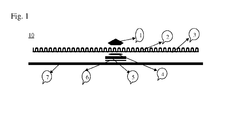
- Fig. 1 shows (in cross section) an exploded view of an embodiment of a textile floor covering according to the invention.
- a textile floor covering 10 which comprises a back-side carrier layer 7, a front-side textile layer 2 and a decorative object 1 on the surface of the textile layer 2.
- the decorative object 1 is connected to the textile layer 2 via a connecting element 4.
- the ornamental item 1 is a gemstone 1 or a crystal, which has on its rear side a holding element with projections not shown in detail.
- claws may be provided which engage in recesses also not shown in detail on the connecting element 4 and thus enter into a non-positive operative connection. By mechanical deformation of the claws, the connection between the connecting element 4 and decorative item 1 is permanently stable.
- the non-positive connection between the holding element and the connecting element 4 is so stable that a rotation of the Ornamental item 1 around its own axis is no longer possible.
- the decorative item 1 thus remains substantially rigidly attached to the textile layer 2.
- the decorative objects for example in the form of gemstones such as crystals, are already integrated in retaining elements, which also form a socket for the respective ornamental item.
- the connecting element 4 is arranged between the rear-side carrier layer 7 and the front-side textile layer 2. Between the connecting element 4 and the carrier layer 7, an intermediate layer 5, 6 is arranged.
- the intermediate layer 5, 6 comprises two layers 5, 6.
- the first layer 5 closer to the textile layer 2 comprises a nonwoven fabric.
- the second layer 6 closer to the carrier layer 7 comprises an elastomer.
- At the places where the decorative item 1 is introduced was a 30 mm x 30 mm piece of Tuftvlies (weight 100 g / m 2 nonwoven Colbond or Lutradur) as the first layer 5 of the intermediate layer and a piece of rubber with the same dimension as second layer 6, the intermediate layer inserted. This "sandwich" is then connected by vulcanization.
- the textile component is also connected to the rubber and the finished mat is created.
- the back support layer 7 is made of an elastomer made of vulcanized rubber (rubber).
- the second layer 6 of the intermediate layer is made of rubber and vulcanized rubber.
- the vulcanization of the rubber of the second layer 6 of the intermediate layer and of the rubber of the back-side carrier layer 7 takes place simultaneously, so that the second layer 6 of the intermediate layer and the back-side carrier layer 7 form a permanent cohesive connection with each other.
- the fleece of the first layer 5 of the intermediate layer is also embedded in the rubber layers and improves the stability of the resulting sandwich.
- the back carrier layer 7 forms a continuous rubber back, which can be made in different dimensions. However, preferred thicknesses of the carrier layer 7 are between 1.2 mm and 1.4 mm.
- the front-side textile layer 2 consists of a base material 3, which in the present example is a so-called tuft carrier.
- the base material 3 or the tuft carrier of the textile layer 2 can be a woven fabric or a nonwoven fabric (nonwoven). In the example, a nonwoven fabric is provided.
- the pile threads in the example shown as so-called Schlingenware.
- the pile threads are - as is known - tufted. There were embodiments with pile threads of thermoplastic and natural fibers realized equally, for example of polyamide and cotton.
- the textile layer 2 is preferably also printed.
- the textile floor covering 10 is then also referred to as decorative mat, individual foot or logo mat.
Landscapes
- Engineering & Computer Science (AREA)
- Textile Engineering (AREA)
- Floor Finish (AREA)
- Laminated Bodies (AREA)
Abstract
Description
- Die Erfindung betrifft einen textilen Bodenbelag, umfassend eine rückseitige Trägerschicht, eine vorderseitige Textilschicht und wenigstens einen Ziergegenstand an der Oberfläche der Textilschicht, wobei der Ziergegenstand mit der Textilschicht über ein Verbindungselement verbunden ist. Die Erfindung betrifft weiters ein Verfahren zur Herstellung eines textilen Bodenbelags, umfassend eine rückseitige Trägerschicht, eine vorderseitige Textilschicht und wenigstens einen Ziergegenstand an der Oberfläche der Textilschicht, wobei der Ziergegenstand mit der Textilschicht über ein Verbindungselement verbunden wird.
- Textile Bodenbeläge sind aus dem Stand der Technik beispielsweise in Form sogenannter individueller Fuß- und Logomatten bekannt. Beim Stand der Technik wird der textile Bodenbelag, zu Verzierungszwecken nicht nur bedruckt, sondern es werden auch Ziergegenstände wie Schmucksteine, Edelsteine und dergleichen in die Textilschicht ein- oder auf die Textilschicht aufgebracht. Dabei wird der Ziergegenstand über Verbindungselemente - zum Beispiel über Nietverbindungen - mit dem Bodenbelag verbunden. Beim Stand der Technik wird der Ziergegenstand an der Textilschicht positioniert und über das Verbindungselement, welches an der Rückseite des textilen Bodenbelags - also an der Trägerschicht - sitzt, fixiert.
- Durch starke Beanspruchung und Reinigung des textilen Bodenbelags kommt es leider häufig dazu, dass das Verbindungselement den Beanspruchungen nicht standhält und zerstört wird oder verloren geht.
- Aufgabe der vorliegenden Erfindung ist es daher, einen textilen Bodenbelag sowie ein Verfahren zur Herstellung eines textilen Bodenbelags der jeweils eingangs genannten Art bereit zu stellen, bei denen diese Probleme vermindert sind.
- Die Aufgabe wird gelöst durch einen textilen Bodenbelag, umfassend
- eine rückseitige Trägerschicht,
- eine vorderseitige Textilschicht und
- wenigstens einen Ziergegenstand an der Oberfläche der Textilschicht, wobei der Ziergegenstand mit der Textilschicht über ein Verbindungselement verbunden ist, welcher dadurch gekennzeichnet ist, dass das Verbindungselement zwischen der Trägerschicht und der Textilschicht angeordnet ist, wobei zwischen Verbindungselement und Trägerschicht zumindest eine Zwischenlage angeordnet ist.
- Ferner wird die Aufgabe gelöst durch ein Verfahren zur Herstellung eines textilen Bodenbelags, umfassend eine rückseitige Trägerschicht, eine vorderseitige Textilschicht und wenigstens einen Ziergegenstand an der Oberfläche der Textilschicht, wobei der Ziergegenstand mit der Textilschicht über ein Verbindungselement verbunden wird, welches dadurch gekennzeichnet ist, dass das Verbindungselement zwischen Trägerschicht und Textilschicht eingebracht wird, wobei zwischen Verbindungselement und Trägerschicht zumindest eine Zwischenlage eingebracht wird.
- Die Erfindung beruht auf der Erkenntnis, dass die Verlagerung des Verbindungselementes in das Innere des textilen Bodenbelags und das Dazwischenschalten einer Zwischenlage zwischen Trägerschicht und Verbindungselement die Beanspruchungen am Verbindungselement derart abgemildert werden, dass der Ziergegenstand dauerhaft am Bodenbelag hält, und dass der Bodenbelag durch das Verbindungselement oberflächlich nicht beschädigt wird.
- Zunächst werden nachfolgend vorteilhafte Ausgestaltungen des textilen Bodenbelags näher erläutert.
- Bevorzugt ist vorgesehen, dass die Zwischenlage ein Vlies umfasst. Mit einem Vlies kann kostengünstig eine stabile Zwischenlage erstellt werden. Bevorzugt weist das Vlies ein Massengewicht von 60 g/m2 bis 200 g/m2 auf. Dieser Bereich stellt einen idealen Kompromiss zwischen hoher Stabilität einerseits, aber dennoch geringer Dicke und damit geringer Verformung des Bodenbelags andererseits, dar.
- Bevorzugt ist vorgesehen, dass die Zwischenlage ein Elastomer umfasst, da auch so eine besonders stabile Zwischenlage erstellt werden kann.
- In einer besonders bevorzugten Ausführungsvariante ist vorgesehen, dass die Zwischenlage wenigstens zwei Schichten umfasst, wobei die erste Schicht ein Vlies und die zweite Schicht ein Elastomer umfasst. Diese Ausgestaltung hat sich als die stabilste Variante herausgestellt. Bevorzugt ist dabei vorgesehen, dass die zweite Schicht mit dem Elastomer der Trägerschicht zugewandt ist. Beim Elastomer der Trägerschicht kann es sich um ein thermoplastisches Elastomer handeln, wie z.B. auf PVC-Basis (Polyvinylchlorid). Wenn die Trägerschicht ebenfalls ein thermoplastisches Elastomer aufweist, könnten die zweite Schicht und die Trägerschicht dauerhaft miteinander verbunden werden.
- Einige thermoplastische Elastomere, wie z.B. PVC, sind nicht ausreichend stabil, damit der textile Bodenbelag mehrfaches Reinigen in Großreinigungsanlagen übersteht. Daher ist in einer bevorzugten Ausführungsvariante vorgesehen, dass die zweite das Elastomer umfassende Schicht Kautschuk, vorzugsweise vulkanisierten Kautuschuk, umfasst, da Kautschukelastomere temperaturstabil und mechanisch stabil sind. Grundsätzlich sind jegliche Kautschuksorten denkbar, wie NBR, EPDM, SBR, usw.
- Bevorzugt ist vorgesehen, dass die Trägerschicht ein Elastomer umfasst. Wie bereits ausgeführt, kann das Elastomer ein thermoplastisches Elastomer, beispielsweise auf PVC-Basis sein.
- Aus Stabilitätsgründen ist auch hier bevorzugt vorgesehen sein, dass das Elastomer der Trägerschicht Kautschuk, vorzugsweise vulkanisiertes Kautuschuk, umfasst.
- Bevorzugt ist vorgesehen, dass die Textilschicht ein Grundmaterial und - vorzugsweise getuftete - Polfäden umfasst. Bei textilen Bodenbelägen wird die textile Schicht der Oberfläche als Flor oder Pol bezeichnet, welcher aus Polfäden besteht. Die Polschicht bezeichnet die Gesamtmenge des Fasermaterials.
- Bevorzugt kann vorgesehen sein, dass die Polfäden Naturfasern, vorzugsweise Baumwolle und/oder thermoplastische Polymerfasern, vorzugsweise ausgewählt aus der Gruppe Polyamid, Polyester, PET oder Mischungen daraus, umfassen.
- Der Pol kann aufgeschnitten sein (cut pile) oder alternativ dazu eine Schlingenware (loop pile) sein. Auch ein Nadelfilz - also aus allen Textilen, die auch für die Teppiche und Matten in der Industrie üblicherweise verwendet werden - kann der textile Bestandteil bestehen.
- Weiters kann vorgesehen sein, dass das Grundmaterial der Textilschicht ein Gewebe oder einen Vliesstoff (Nonwoven) umfasst.
- Als Ziergegenstand sind beispielsweise Schmucksteine, Edelsteine, Glassteine, Perlen oder andere dekorative Elemente angedacht. Bevorzugt weist der Ziergegenstand ein Halteelement auf, welches mit dem Verbindungselement kraftschlüssig verbindbar ist. Beispielsweise kann dabei vorgesehen sein, dass die kraftschlüssige Verbindung zwischen Halteelement und Verbindungselement aus Vorsprüngen und entsprechenden Ausnehmungen gebildet wird, wobei die Vorsprünge eine kraftschlüssige Wirkverbindung mit den Ausnehmungen bilden, wobei die Vorsprünge und die Ausnehmungen derart ausgebildet sind, dass der Ziergegenstand im Wesentlichen starr an der Textilschicht bleibt - insbesondere derart, dass keine Rotation des Ziergegenstands um die eigene Achse möglich ist. Mögliche Verbindungen inkludieren zum Beispiel Nietverbindungen, Klammern, Druckknöpfe und dergleichen.
- Vorteilhafte Ausgestaltungen des Verfahrens zur Herstellung des textilen Bodenbelags werden nachfolgend näher erläutert.
- Bevorzugt ist beim erfindungsgemäßen Verfahren vorgesehen, dass als Zwischenlage zumindest ein Vlies eingebracht wird.
- Weiters kann vorgesehen sein, dass als Zwischenlage zumindest ein Elastomer eingebracht wird.
- Besonders bevorzugt ist vorgesehen, dass wenigstens zwei Schichten als Zwischenlage eingebracht werden, wobei die erste Schicht ein Vlies und die zweite Schicht ein Elastomer umfasst. Dabei ist bevorzugt vorgesehen, dass die zweite Schicht der Trägerschicht zugewandt ist. Eine vorteilhafte Ausgestaltung sieht vor, dass die zweite Schicht Kautschuk, vorzugsweise vulkanisiertes Kautschuk, umfasst.
- In einer Ausführungsvariante ist vorgesehen, dass die Trägerschicht ein Elastomer umfasst. Bevorzugt ist dabei vorgesehen, dass das Elastomer Kautschuk, vorzugsweise vulkanisiertes Kautschuk, umfasst. Eine besonders bevorzugte Ausführungsvariante sieht vor, dass die zweite Schicht der Zwischenlage und die Trägerschicht Kautschuk umfassen und durch Vulkanisieren miteinander - vorzugsweise stoffschlüssig - verbunden werden.
- In einer Variante kann vorgesehen sein, dass die Textilschicht ein Grundmaterial und - vorzugsweise getuftete - Polfäden umfasst. Bevorzugte Ausführungsvarianten sehen vor, dass die Polfäden Naturfasern, vorzugsweise Baumwolle und/oder thermoplastische Polymerfasern, vorzugsweise ausgewählt aus der Gruppe Polyamid, Polyester, PET oder Mischungen daraus, umfassen.
- Eine weitere vorteilhafte Ausgestaltung der Erfindung kann vorsehen, dass das Grundmaterial der Textilschicht ein Gewebe oder einen Vliesstoff (Nonwoven) umfasst.
- Eine Ausführungsvariante der Erfindung sieht vor, dass der Ziergegenstand ein Halteelement aufweist, welches mit dem Verbindungselement kraftschlüssig verbunden wird. Dabei ist vorteilhafterweise vorgesehen, dass die kraftschlüssige Verbindung zwischen Halteelement und Verbindungselement aus Vorsprüngen und entsprechenden Ausnehmungen gebildet wird, wobei die Vorsprünge eine kraftschlüssige Wirkverbindung mit den Ausnehmungen bilden, wobei die Vorsprünge und die Ausnehmungen derart ausgebildet sind, dass der Ziergegenstand im Wesentlichen starr an der Textilschicht bleibt.
- Weitere Vorteile und Details der Erfindung werden nachfolgend anhand der Figuren und der dazugehörigen Figurenbeschreibung erläutert.
-
Fig. 1 zeigt (im Querschnitt) eine Explosionsdarstellung eines Ausführungsbeispiels eines erfindungsgemäßen textilen Bodenbelags. - In
Fig. 1 ist ein textiler Bodenbelag 10 erkennbar, der eine rückseitige Trägerschicht 7, eine vorderseitige Textilschicht 2 und einen Ziergegenstand 1 an der Oberfläche der Textilschicht 2 umfasst. Der Ziergegenstand 1 ist mit der Textilschicht 2 über ein Verbindungselement 4 verbunden. Beim Ziergegenstand 1 handelt es sich um einen Schmuckstein 1 bzw. einen Kristall, der an seiner Rückseite ein Halteelement mit nicht näher gezeigten Vorsprüngen aufweist. Beispielsweise können Krallen vorgesehen sein, die in ebenfalls nicht näher gezeigte Ausnehmungen am Verbindungselement 4 eingreifen und so eine kraftschlüssige Wirkverbindung eingehen. Durch mechanische Verformung der Krallen wird die Verbindung zwischen Verbindungselement 4 und Ziergegenstand 1 dauerhaft stabil. Wenn zum Beispiel mindestens drei solcher Vorsprünge vorgesehen sind, wird die kraftschlüssige Verbindung zwischen Halteelement und Verbindungselement 4 so stabil, dass eine Rotation des Ziergegenstands 1 um die eigene Achse nicht mehr möglich wird. Der Ziergegenstand 1 verbleibt dadurch im Wesentlichen starr an der Textilschicht 2. Die Ziergegenstände z.B. in Form von Schmucksteinen wie Kristallen sind bereits in Haltelemente integriert, welche außerdem eine Fassung für den jeweiligen Ziergegenstand bilden. - Das Verbindungselement 4 ist zwischen der rückseitigen Trägerschicht 7 und der vorderseitigen Textilschicht 2 angeordnet. Zwischen dem Verbindungselement 4 und der Trägerschicht 7 ist eine Zwischenlage 5, 6 angeordnet. Die Zwischenlage 5, 6 umfasst zwei Schichten 5, 6. Die der Textilschicht 2 näher gelegene erste Schicht 5 umfasst ein Vlies. Die der Trägerschicht 7 näher gelegene zweite Schicht 6, umfasst ein Elastomer. An den Stellen, wo der Ziergegenstand 1 eingebracht wird, wurde ein ca. 30 mm x 30 mm großes Stück Tuftvlies (Gewicht 100 g/m2 nonwoven der Firma Colbond oder Lutradur) als erste Schicht 5 der Zwischenlage und ein Kautschukstück mit gleicher Dimension als zweite Schicht 6, der Zwischenlage eingelegt. Dieses "Sandwich" wird dann mittels Vulkanisation verbunden. Dabei wird auch der textile Bestandteil mit dem Gummi verbunden und es entsteht die fertige Matte.
- Die rückseitige Trägerschicht 7 besteht aus einem Elastomer, und zwar aus vulkanisiertem Kautschuk (Gummi). Auch die zweite Schicht 6 der Zwischenlage besteht aus Kautschuk und zwar vulkanisiertem Kautschuk. Die Vulkanisierung des Kautschuks der zweiten Schicht 6 der Zwischenlage und des Kautschuks der rückseitigen Trägerschicht 7 erfolgt gleichzeitig, sodass die zweite Schicht 6 der Zwischenlage und die rückseitige Trägerschicht 7 eine dauerhafte stoffschlüssige Verbindung miteinander eingehen. Das Vlies der ersten Schicht 5 der Zwischenlage wird dabei ebenfalls in die Gummischichten eingebettet und verbessert die Stabilität des so entstandenen Sandwichs. Die rückseitige Trägerschicht 7 bildet einen durchgehenden Gummirücken, der in verschiedenen Dimensionen gefertigt werden kann. Bevorzugte Dicken der Trägerschicht liegen 7 jedoch zwischen 1,2 mm und 1,4 mm.
- Die vorderseitige Textilschicht 2 besteht aus einem Grundmaterial 3, das im vorliegenden Beispiel ein sogenannter Tuftträger ist. Das Grundmaterial 3 bzw. der Tuftträger der Textilschicht 2 kann dabei ein Gewebe oder ein Vliesstoff (Nonwoven) sein. Im Beispiel ist ein Vliesstoff vorgesehen. In den Tuftträger 3 bzw. das Grundmaterial 3 eingebracht sind die Polfäden, im gezeigten Beispiel als sogenannte Schlingenware. Die Polfäden sind - wie an sich bekannt - getuftet. Es wurden Ausführungsbeispiele mit Polfäden aus thermoplastischen und Naturfasern gleichermaßen realisiert, beispielsweise aus Polyamid und aus Baumwolle. Die Textilschicht 2 ist bevorzugt auch bedruckt. Der textile Bodenbelag 10 wird dann auch als Dekormatte, individuelle Fuß- oder Logomatte bezeichnet.
Claims (15)
- Textiler Bodenbelag (10), umfassend- eine rückseitige Trägerschicht (7),- eine vorderseitige Textilschicht (2) und- wenigstens einen Ziergegenstand (1) an der Oberfläche der Textilschicht (2), wobei der Ziergegenstand (1) mit der Textilschicht (2) über ein Verbindungselement (4) verbunden ist, dadurch gekennzeichnet, dass das Verbindungselement (4) zwischen der Trägerschicht (7) und der Textilschicht (2) angeordnet ist, wobei zwischen Verbindungselement (4) und Trägerschicht (7) zumindest eine Zwischenlage (5, 6) angeordnet ist.
- Bodenbelag nach Anspruch 1, dadurch gekennzeichnet, dass die Zwischenlage (5, 6) ein Vlies umfasst.
- Bodenbelag nach Anspruch 1 oder Anspruch 2, dadurch gekennzeichnet, dass die Zwischenlage (5, 6) ein Elastomer umfasst.
- Bodenbelag nach einem der Ansprüche 1 bis 3, dadurch gekennzeichnet, dass die Zwischenlage (5, 6) wenigstens zwei Schichten umfasst, wobei die erste Schicht (5) ein Vlies und die zweite Schicht (6) ein Elastomer umfasst.
- Bodenbelag nach Anspruch 4, dadurch gekennzeichnet, dass die zweite Schicht (6) der Zwischenlage der Trägerschicht (7) zu- und die erste Schicht (5) der Zwischenlage der Trägschicht (7) abgewandt ist.
- Bodenbelag nach Anspruch 5, dadurch gekennzeichnet, dass die zweite Schicht (6) der Zwischenlage Kautschuk, vorzugsweise vulkanisiertes Kautschuk, umfasst.
- Bodenbelag nach einem der Ansprüche 1 bis 6, dadurch gekennzeichnet, dass die Trägerschicht (7) ein Elastomer umfasst.
- Bodenbelag nach Anspruch 7, dadurch gekennzeichnet, dass das Elastomer der Trägerschicht (7) Kautschuk, vorzugsweise vulkanisiertes Kautschuk, umfasst.
- Bodenbelag nach einem der Ansprüche 1 bis 8, dadurch gekennzeichnet, dass der Ziergegenstand (1) ein Halteelement aufweist, welches mit dem Verbindungselement (4) kraftschlüssig verbindbar ist.
- Verfahren zur Herstellung eines textilen Bodenbelags (10), umfassend eine rückseitige Trägerschicht (7), eine vorderseitige Textilschicht (2) und wenigstens einen Ziergegenstand (1) an der Oberfläche der Textilschicht (2), wobei der Ziergegenstand (1) mit der Textilschicht (2) über ein Verbindungselement (4) verbunden wird, dadurch gekennzeichnet, dass das Verbindungselement (4) zwischen Trägerschicht (7) und Textilschicht (2) eingebracht wird, wobei zwischen Verbindungselement (4) und Trägerschicht (7) zumindest eine Zwischenlage (5, 6) eingebracht wird.
- Verfahren nach Anspruch 10, dadurch gekennzeichnet, dass als Zwischenlage (5, 6) zumindest ein Vlies eingebracht wird.
- Verfahren nach Anspruch 10 oder Anspruch 11, dadurch gekennzeichnet, dass als Zwischenlage (5, 6) zumindest ein Elastomer eingebracht wird.
- Verfahren nach einem der Ansprüche 10 bis 12, dadurch gekennzeichnet, dass wenigstens zwei Schichten (5, 6) als Zwischenlage (5, 6) eingebracht werden, wobei die erste Schicht (5) ein Vlies und die zweite Schicht (6) ein Elastomer umfasst.
- Verfahren nach Anspruch 13, dadurch gekennzeichnet, dass die zweite Schicht (6) der Zwischenlage (5, 6) der Trägerschicht (7) zu- und die erste Schicht (5) der Zwischenlage (5, 6) der Trägerschicht (7) gewandt ist.
- Verfahren nach einem der Ansprüche 10 bis 14, dadurch gekennzeichnet, dass der Ziergegenstand (1) ein Halteelement aufweist, welches mit dem Verbindungselement (4) kraftschlüssig verbindbar ist.
Priority Applications (1)
| Application Number | Priority Date | Filing Date | Title |
|---|---|---|---|
| EP20110170710 EP2537978B1 (de) | 2011-06-21 | 2011-06-21 | Textiler Bodenbelag |
Applications Claiming Priority (1)
| Application Number | Priority Date | Filing Date | Title |
|---|---|---|---|
| EP20110170710 EP2537978B1 (de) | 2011-06-21 | 2011-06-21 | Textiler Bodenbelag |
Publications (2)
| Publication Number | Publication Date |
|---|---|
| EP2537978A1 true EP2537978A1 (de) | 2012-12-26 |
| EP2537978B1 EP2537978B1 (de) | 2014-10-15 |
Family
ID=44905336
Family Applications (1)
| Application Number | Title | Priority Date | Filing Date |
|---|---|---|---|
| EP20110170710 Not-in-force EP2537978B1 (de) | 2011-06-21 | 2011-06-21 | Textiler Bodenbelag |
Country Status (1)
| Country | Link |
|---|---|
| EP (1) | EP2537978B1 (de) |
Citations (1)
| Publication number | Priority date | Publication date | Assignee | Title |
|---|---|---|---|---|
| US20090104416A1 (en) * | 2007-10-19 | 2009-04-23 | Jung Soon Chang | Decorated fabric for automotive use |
-
2011
- 2011-06-21 EP EP20110170710 patent/EP2537978B1/de not_active Not-in-force
Patent Citations (1)
| Publication number | Priority date | Publication date | Assignee | Title |
|---|---|---|---|---|
| US20090104416A1 (en) * | 2007-10-19 | 2009-04-23 | Jung Soon Chang | Decorated fabric for automotive use |
Also Published As
| Publication number | Publication date |
|---|---|
| EP2537978B1 (de) | 2014-10-15 |
Similar Documents
| Publication | Publication Date | Title |
|---|---|---|
| EP3373769B1 (de) | Verfahren zur herstellung eines textilen verbundmaterials sowie auf diese weise hergestelltes textiles verbundmaterial | |
| DE69828427T2 (de) | Bodenbelag mit gewebtem obermaterial | |
| EP0547533A1 (de) | Spannbarer textiler Fussbodenbelag | |
| EP2653607B1 (de) | Verfahren zum Herstellen eines Kunstleders | |
| DE102009044636A1 (de) | Nahtaufbau eines Sichtlageteils zum Abdecken eines Fahrzeugsitzes, Verfahren zur Herstellung desselben und Airbagaufbau für einen Fahrzeugsitz | |
| WO2013170869A1 (de) | Textiles flächengebilde, verwendung und herstellung eines textilen flächengebildes und möbelelement | |
| EP1555118B1 (de) | Leder- oder Lederähnliches Verbundmaterial | |
| EP2537978B1 (de) | Textiler Bodenbelag | |
| AT500461A1 (de) | Verfahren zum aufbringen von flexiblen flächengebilden auf rigide substrate | |
| EP3149232B1 (de) | Schleifvorrichtung zur lösbaren festlegung an einem klettverschluss | |
| CH614853A5 (en) | Woven or tufted pile-carpet web which can be used as a foot scraper | |
| CH708682A1 (de) | Garniturträger. | |
| EP2537977B1 (de) | Textiler Bodenbelag | |
| EP2990434B1 (de) | Sitzbezug mit einem abstandstextil, sitz damit und verfahren zum herstellen eines sitzbezugs | |
| AT407237B (de) | Kaschierverfahren | |
| DE102014000417A1 (de) | Thermisch fixierbares Flächengebilde | |
| DE202012005465U1 (de) | Textiles Flächengebilde und Möbelelement | |
| DE3313681A1 (de) | Textilverbundstoff, verfahren zu seiner herstellung und dessen verwendung | |
| DE597899C (de) | Teppich | |
| DE2544033A1 (de) | Teppichunterlage | |
| WO2020038711A1 (de) | Verlournadelverbundvliesstoff | |
| DE102007013163B4 (de) | Verfahren zur Herstellung von mehrschichtigen Kunststofffolien | |
| DE10117354A1 (de) | Thermofixierte Prägung auf Nadelvlies-Bodenbelag | |
| DE202012013364U1 (de) | Verbundwerkstoff | |
| EP1145910A3 (de) | Fahrzeug-Innenauskleidungsteil |
Legal Events
| Date | Code | Title | Description |
|---|---|---|---|
| PUAI | Public reference made under article 153(3) epc to a published international application that has entered the european phase |
Free format text: ORIGINAL CODE: 0009012 |
|
| AK | Designated contracting states |
Kind code of ref document: A1 Designated state(s): AL AT BE BG CH CY CZ DE DK EE ES FI FR GB GR HR HU IE IS IT LI LT LU LV MC MK MT NL NO PL PT RO RS SE SI SK SM TR |
|
| AX | Request for extension of the european patent |
Extension state: BA ME |
|
| 17P | Request for examination filed |
Effective date: 20130625 |
|
| RBV | Designated contracting states (corrected) |
Designated state(s): AL AT BE BG CH CY CZ DE DK EE ES FI FR GB GR HR HU IE IS IT LI LT LU LV MC MK MT NL NO PL PT RO RS SE SI SK SM TR |
|
| RIC1 | Information provided on ipc code assigned before grant |
Ipc: D06N 7/00 20060101AFI20130724BHEP Ipc: E04F 15/10 20060101ALI20130724BHEP |
|
| 17Q | First examination report despatched |
Effective date: 20131219 |
|
| GRAP | Despatch of communication of intention to grant a patent |
Free format text: ORIGINAL CODE: EPIDOSNIGR1 |
|
| INTG | Intention to grant announced |
Effective date: 20140520 |
|
| GRAS | Grant fee paid |
Free format text: ORIGINAL CODE: EPIDOSNIGR3 |
|
| GRAA | (expected) grant |
Free format text: ORIGINAL CODE: 0009210 |
|
| AK | Designated contracting states |
Kind code of ref document: B1 Designated state(s): AL AT BE BG CH CY CZ DE DK EE ES FI FR GB GR HR HU IE IS IT LI LT LU LV MC MK MT NL NO PL PT RO RS SE SI SK SM TR |
|
| REG | Reference to a national code |
Ref country code: GB Ref legal event code: FG4D Free format text: NOT ENGLISH Ref country code: CH Ref legal event code: EP |
|
| REG | Reference to a national code |
Ref country code: IE Ref legal event code: FG4D Free format text: LANGUAGE OF EP DOCUMENT: GERMAN |
|
| REG | Reference to a national code |
Ref country code: AT Ref legal event code: REF Ref document number: 691757 Country of ref document: AT Kind code of ref document: T Effective date: 20141115 |
|
| REG | Reference to a national code |
Ref country code: DE Ref legal event code: R096 Ref document number: 502011004666 Country of ref document: DE Effective date: 20141127 |
|
| REG | Reference to a national code |
Ref country code: NL Ref legal event code: T3 |
|
| REG | Reference to a national code |
Ref country code: CH Ref legal event code: NV Representative=s name: SCHMAUDER AND PARTNER AG PATENT- UND MARKENANW, CH |
|
| REG | Reference to a national code |
Ref country code: LT Ref legal event code: MG4D |
|
| PG25 | Lapsed in a contracting state [announced via postgrant information from national office to epo] |
Ref country code: PT Free format text: LAPSE BECAUSE OF FAILURE TO SUBMIT A TRANSLATION OF THE DESCRIPTION OR TO PAY THE FEE WITHIN THE PRESCRIBED TIME-LIMIT Effective date: 20150216 Ref country code: LT Free format text: LAPSE BECAUSE OF FAILURE TO SUBMIT A TRANSLATION OF THE DESCRIPTION OR TO PAY THE FEE WITHIN THE PRESCRIBED TIME-LIMIT Effective date: 20141015 Ref country code: ES Free format text: LAPSE BECAUSE OF FAILURE TO SUBMIT A TRANSLATION OF THE DESCRIPTION OR TO PAY THE FEE WITHIN THE PRESCRIBED TIME-LIMIT Effective date: 20141015 Ref country code: FI Free format text: LAPSE BECAUSE OF FAILURE TO SUBMIT A TRANSLATION OF THE DESCRIPTION OR TO PAY THE FEE WITHIN THE PRESCRIBED TIME-LIMIT Effective date: 20141015 Ref country code: NO Free format text: LAPSE BECAUSE OF FAILURE TO SUBMIT A TRANSLATION OF THE DESCRIPTION OR TO PAY THE FEE WITHIN THE PRESCRIBED TIME-LIMIT Effective date: 20150115 Ref country code: IS Free format text: LAPSE BECAUSE OF FAILURE TO SUBMIT A TRANSLATION OF THE DESCRIPTION OR TO PAY THE FEE WITHIN THE PRESCRIBED TIME-LIMIT Effective date: 20150215 |
|
| PG25 | Lapsed in a contracting state [announced via postgrant information from national office to epo] |
Ref country code: SE Free format text: LAPSE BECAUSE OF FAILURE TO SUBMIT A TRANSLATION OF THE DESCRIPTION OR TO PAY THE FEE WITHIN THE PRESCRIBED TIME-LIMIT Effective date: 20141015 Ref country code: HR Free format text: LAPSE BECAUSE OF FAILURE TO SUBMIT A TRANSLATION OF THE DESCRIPTION OR TO PAY THE FEE WITHIN THE PRESCRIBED TIME-LIMIT Effective date: 20141015 Ref country code: PL Free format text: LAPSE BECAUSE OF FAILURE TO SUBMIT A TRANSLATION OF THE DESCRIPTION OR TO PAY THE FEE WITHIN THE PRESCRIBED TIME-LIMIT Effective date: 20141015 Ref country code: LV Free format text: LAPSE BECAUSE OF FAILURE TO SUBMIT A TRANSLATION OF THE DESCRIPTION OR TO PAY THE FEE WITHIN THE PRESCRIBED TIME-LIMIT Effective date: 20141015 Ref country code: CY Free format text: LAPSE BECAUSE OF FAILURE TO SUBMIT A TRANSLATION OF THE DESCRIPTION OR TO PAY THE FEE WITHIN THE PRESCRIBED TIME-LIMIT Effective date: 20141015 Ref country code: GR Free format text: LAPSE BECAUSE OF FAILURE TO SUBMIT A TRANSLATION OF THE DESCRIPTION OR TO PAY THE FEE WITHIN THE PRESCRIBED TIME-LIMIT Effective date: 20150116 Ref country code: RS Free format text: LAPSE BECAUSE OF FAILURE TO SUBMIT A TRANSLATION OF THE DESCRIPTION OR TO PAY THE FEE WITHIN THE PRESCRIBED TIME-LIMIT Effective date: 20141015 |
|
| REG | Reference to a national code |
Ref country code: FR Ref legal event code: PLFP Year of fee payment: 5 |
|
| REG | Reference to a national code |
Ref country code: DE Ref legal event code: R097 Ref document number: 502011004666 Country of ref document: DE |
|
| PG25 | Lapsed in a contracting state [announced via postgrant information from national office to epo] |
Ref country code: SK Free format text: LAPSE BECAUSE OF FAILURE TO SUBMIT A TRANSLATION OF THE DESCRIPTION OR TO PAY THE FEE WITHIN THE PRESCRIBED TIME-LIMIT Effective date: 20141015 Ref country code: EE Free format text: LAPSE BECAUSE OF FAILURE TO SUBMIT A TRANSLATION OF THE DESCRIPTION OR TO PAY THE FEE WITHIN THE PRESCRIBED TIME-LIMIT Effective date: 20141015 Ref country code: CZ Free format text: LAPSE BECAUSE OF FAILURE TO SUBMIT A TRANSLATION OF THE DESCRIPTION OR TO PAY THE FEE WITHIN THE PRESCRIBED TIME-LIMIT Effective date: 20141015 Ref country code: DK Free format text: LAPSE BECAUSE OF FAILURE TO SUBMIT A TRANSLATION OF THE DESCRIPTION OR TO PAY THE FEE WITHIN THE PRESCRIBED TIME-LIMIT Effective date: 20141015 Ref country code: RO Free format text: LAPSE BECAUSE OF FAILURE TO SUBMIT A TRANSLATION OF THE DESCRIPTION OR TO PAY THE FEE WITHIN THE PRESCRIBED TIME-LIMIT Effective date: 20141015 |
|
| PGFP | Annual fee paid to national office [announced via postgrant information from national office to epo] |
Ref country code: CH Payment date: 20150618 Year of fee payment: 5 Ref country code: LU Payment date: 20150624 Year of fee payment: 5 |
|
| PLBE | No opposition filed within time limit |
Free format text: ORIGINAL CODE: 0009261 |
|
| STAA | Information on the status of an ep patent application or granted ep patent |
Free format text: STATUS: NO OPPOSITION FILED WITHIN TIME LIMIT |
|
| PGFP | Annual fee paid to national office [announced via postgrant information from national office to epo] |
Ref country code: FR Payment date: 20150619 Year of fee payment: 5 Ref country code: BE Payment date: 20150618 Year of fee payment: 5 Ref country code: NL Payment date: 20150618 Year of fee payment: 5 |
|
| 26N | No opposition filed |
Effective date: 20150716 |
|
| PGFP | Annual fee paid to national office [announced via postgrant information from national office to epo] |
Ref country code: IT Payment date: 20150622 Year of fee payment: 5 |
|
| PG25 | Lapsed in a contracting state [announced via postgrant information from national office to epo] |
Ref country code: MC Free format text: LAPSE BECAUSE OF FAILURE TO SUBMIT A TRANSLATION OF THE DESCRIPTION OR TO PAY THE FEE WITHIN THE PRESCRIBED TIME-LIMIT Effective date: 20141015 |
|
| GBPC | Gb: european patent ceased through non-payment of renewal fee |
Effective date: 20150621 |
|
| PG25 | Lapsed in a contracting state [announced via postgrant information from national office to epo] |
Ref country code: SI Free format text: LAPSE BECAUSE OF FAILURE TO SUBMIT A TRANSLATION OF THE DESCRIPTION OR TO PAY THE FEE WITHIN THE PRESCRIBED TIME-LIMIT Effective date: 20141015 |
|
| REG | Reference to a national code |
Ref country code: IE Ref legal event code: MM4A |
|
| PG25 | Lapsed in a contracting state [announced via postgrant information from national office to epo] |
Ref country code: IE Free format text: LAPSE BECAUSE OF NON-PAYMENT OF DUE FEES Effective date: 20150621 Ref country code: GB Free format text: LAPSE BECAUSE OF NON-PAYMENT OF DUE FEES Effective date: 20150621 |
|
| PG25 | Lapsed in a contracting state [announced via postgrant information from national office to epo] |
Ref country code: MT Free format text: LAPSE BECAUSE OF FAILURE TO SUBMIT A TRANSLATION OF THE DESCRIPTION OR TO PAY THE FEE WITHIN THE PRESCRIBED TIME-LIMIT Effective date: 20141015 Ref country code: BE Free format text: LAPSE BECAUSE OF NON-PAYMENT OF DUE FEES Effective date: 20160630 |
|
| REG | Reference to a national code |
Ref country code: CH Ref legal event code: PL |
|
| REG | Reference to a national code |
Ref country code: NL Ref legal event code: MM Effective date: 20160701 |
|
| REG | Reference to a national code |
Ref country code: FR Ref legal event code: ST Effective date: 20170228 |
|
| PG25 | Lapsed in a contracting state [announced via postgrant information from national office to epo] |
Ref country code: LI Free format text: LAPSE BECAUSE OF NON-PAYMENT OF DUE FEES Effective date: 20160630 Ref country code: FR Free format text: LAPSE BECAUSE OF NON-PAYMENT OF DUE FEES Effective date: 20160630 Ref country code: CH Free format text: LAPSE BECAUSE OF NON-PAYMENT OF DUE FEES Effective date: 20160630 |
|
| PG25 | Lapsed in a contracting state [announced via postgrant information from national office to epo] |
Ref country code: NL Free format text: LAPSE BECAUSE OF NON-PAYMENT OF DUE FEES Effective date: 20160701 Ref country code: HU Free format text: LAPSE BECAUSE OF FAILURE TO SUBMIT A TRANSLATION OF THE DESCRIPTION OR TO PAY THE FEE WITHIN THE PRESCRIBED TIME-LIMIT; INVALID AB INITIO Effective date: 20110621 Ref country code: SM Free format text: LAPSE BECAUSE OF FAILURE TO SUBMIT A TRANSLATION OF THE DESCRIPTION OR TO PAY THE FEE WITHIN THE PRESCRIBED TIME-LIMIT Effective date: 20141015 Ref country code: BG Free format text: LAPSE BECAUSE OF FAILURE TO SUBMIT A TRANSLATION OF THE DESCRIPTION OR TO PAY THE FEE WITHIN THE PRESCRIBED TIME-LIMIT Effective date: 20141015 |
|
| PG25 | Lapsed in a contracting state [announced via postgrant information from national office to epo] |
Ref country code: IT Free format text: LAPSE BECAUSE OF NON-PAYMENT OF DUE FEES Effective date: 20160621 |
|
| PG25 | Lapsed in a contracting state [announced via postgrant information from national office to epo] |
Ref country code: TR Free format text: LAPSE BECAUSE OF FAILURE TO SUBMIT A TRANSLATION OF THE DESCRIPTION OR TO PAY THE FEE WITHIN THE PRESCRIBED TIME-LIMIT Effective date: 20141015 |
|
| PG25 | Lapsed in a contracting state [announced via postgrant information from national office to epo] |
Ref country code: LU Free format text: LAPSE BECAUSE OF NON-PAYMENT OF DUE FEES Effective date: 20160621 Ref country code: MK Free format text: LAPSE BECAUSE OF FAILURE TO SUBMIT A TRANSLATION OF THE DESCRIPTION OR TO PAY THE FEE WITHIN THE PRESCRIBED TIME-LIMIT Effective date: 20141015 |
|
| PG25 | Lapsed in a contracting state [announced via postgrant information from national office to epo] |
Ref country code: AL Free format text: LAPSE BECAUSE OF FAILURE TO SUBMIT A TRANSLATION OF THE DESCRIPTION OR TO PAY THE FEE WITHIN THE PRESCRIBED TIME-LIMIT Effective date: 20141015 |
|
| PGFP | Annual fee paid to national office [announced via postgrant information from national office to epo] |
Ref country code: AT Payment date: 20190606 Year of fee payment: 9 Ref country code: DE Payment date: 20190624 Year of fee payment: 9 |
|
| REG | Reference to a national code |
Ref country code: DE Ref legal event code: R119 Ref document number: 502011004666 Country of ref document: DE |
|
| REG | Reference to a national code |
Ref country code: AT Ref legal event code: MM01 Ref document number: 691757 Country of ref document: AT Kind code of ref document: T Effective date: 20200621 |
|
| PG25 | Lapsed in a contracting state [announced via postgrant information from national office to epo] |
Ref country code: DE Free format text: LAPSE BECAUSE OF NON-PAYMENT OF DUE FEES Effective date: 20210101 Ref country code: AT Free format text: LAPSE BECAUSE OF NON-PAYMENT OF DUE FEES Effective date: 20200621 |