EP2537734A1 - Servolenksystem - Google Patents
Servolenksystem Download PDFInfo
- Publication number
- EP2537734A1 EP2537734A1 EP12172834A EP12172834A EP2537734A1 EP 2537734 A1 EP2537734 A1 EP 2537734A1 EP 12172834 A EP12172834 A EP 12172834A EP 12172834 A EP12172834 A EP 12172834A EP 2537734 A1 EP2537734 A1 EP 2537734A1
- Authority
- EP
- European Patent Office
- Prior art keywords
- wheels
- steering
- machine
- steering angle
- steer
- Prior art date
- Legal status (The legal status is an assumption and is not a legal conclusion. Google has not performed a legal analysis and makes no representation as to the accuracy of the status listed.)
- Granted
Links
Images


Classifications
-
- B—PERFORMING OPERATIONS; TRANSPORTING
- B62—LAND VEHICLES FOR TRAVELLING OTHERWISE THAN ON RAILS
- B62D—MOTOR VEHICLES; TRAILERS
- B62D7/00—Steering linkage; Stub axles or their mountings
- B62D7/06—Steering linkage; Stub axles or their mountings for individually-pivoted wheels, e.g. on king-pins
- B62D7/14—Steering linkage; Stub axles or their mountings for individually-pivoted wheels, e.g. on king-pins the pivotal axes being situated in more than one plane transverse to the longitudinal centre line of the vehicle, e.g. all-wheel steering
- B62D7/15—Steering linkage; Stub axles or their mountings for individually-pivoted wheels, e.g. on king-pins the pivotal axes being situated in more than one plane transverse to the longitudinal centre line of the vehicle, e.g. all-wheel steering characterised by means varying the ratio between the steering angles of the steered wheels
- B62D7/159—Steering linkage; Stub axles or their mountings for individually-pivoted wheels, e.g. on king-pins the pivotal axes being situated in more than one plane transverse to the longitudinal centre line of the vehicle, e.g. all-wheel steering characterised by means varying the ratio between the steering angles of the steered wheels characterised by computing methods or stabilisation processes or systems, e.g. responding to yaw rate, lateral wind, load, road condition
-
- B—PERFORMING OPERATIONS; TRANSPORTING
- B62—LAND VEHICLES FOR TRAVELLING OTHERWISE THAN ON RAILS
- B62D—MOTOR VEHICLES; TRAILERS
- B62D7/00—Steering linkage; Stub axles or their mountings
- B62D7/06—Steering linkage; Stub axles or their mountings for individually-pivoted wheels, e.g. on king-pins
- B62D7/14—Steering linkage; Stub axles or their mountings for individually-pivoted wheels, e.g. on king-pins the pivotal axes being situated in more than one plane transverse to the longitudinal centre line of the vehicle, e.g. all-wheel steering
- B62D7/148—Steering linkage; Stub axles or their mountings for individually-pivoted wheels, e.g. on king-pins the pivotal axes being situated in more than one plane transverse to the longitudinal centre line of the vehicle, e.g. all-wheel steering provided with safety devices
-
- B—PERFORMING OPERATIONS; TRANSPORTING
- B62—LAND VEHICLES FOR TRAVELLING OTHERWISE THAN ON RAILS
- B62D—MOTOR VEHICLES; TRAILERS
- B62D7/00—Steering linkage; Stub axles or their mountings
- B62D7/06—Steering linkage; Stub axles or their mountings for individually-pivoted wheels, e.g. on king-pins
- B62D7/14—Steering linkage; Stub axles or their mountings for individually-pivoted wheels, e.g. on king-pins the pivotal axes being situated in more than one plane transverse to the longitudinal centre line of the vehicle, e.g. all-wheel steering
- B62D7/15—Steering linkage; Stub axles or their mountings for individually-pivoted wheels, e.g. on king-pins the pivotal axes being situated in more than one plane transverse to the longitudinal centre line of the vehicle, e.g. all-wheel steering characterised by means varying the ratio between the steering angles of the steered wheels
- B62D7/1509—Steering linkage; Stub axles or their mountings for individually-pivoted wheels, e.g. on king-pins the pivotal axes being situated in more than one plane transverse to the longitudinal centre line of the vehicle, e.g. all-wheel steering characterised by means varying the ratio between the steering angles of the steered wheels with different steering modes, e.g. crab-steering, or steering specially adapted for reversing of the vehicle
Definitions
- the invention is directed to a steering system for a four-wheeled two-axle mobile machine, and in particular to a hydraulic steering system suitable for road surface cleaning machines.
- Road cleaning machines also known as sweepers
- Such machines are commonly used to remove unwanted debris from the streets in built-up areas.
- Such machines are typically equipped with brushes, suction equipment, and/or pressure washing systems.
- Such machines are designed for use in confined areas within public spaces, on highways and roads, and often in and amongst traffic within towns and cities.
- FIG. 1 A typical road cleaning machine is shown in Figure 1 .
- the cleaning equipment in this example comprising brushes and debris collection means, is located at the front of the machine in front of the front axle. This arrangement affords good operator control and visibility from an operator/driver control station/cabin at the front of the vehicle.
- Such road cleaning machines conventionally have two selectable modes of operation: a 'work' mode and a 'transit' mode.
- the machine performs its cleaning function, travelling slowly and usually limited to low speeds, for example up to 15 km/hr.
- the machine may be travelling to a place of work or to a place for disposal of the collected debris; speeds in this mode could be up to 50 km/hr, most often travelling alongside and in amongst other road users, and the cleaning functions are automatically inert in this mode.
- the function of the cleaning and collection means is only operable when the machine is set in the 'work' mode.
- the two modes are of equal importance and functionality in the operation of the machine.
- Road cleaning machines as described are typically steered only by the front axle, employing a high degree of articulation in order to achieve a good degree of manoeuvrability. Whilst such machines may have a small turning circle derived by means of the high degree of articulation of the front wheels, they can suffer a disadvantage where the path of the cleaning equipment does not best follow the perimeter of an outer curve. A known solution to this problem exists where the cleaning equipment is moveably linked to the steering function so as to align it with the turning direction. DE-A-3517079 and EP-A-1612335 disclose such systems.
- WO-A-91/19048 discloses a self-propelled driver-operated cleaning vehicle, which has a low speed cleaning mode and a high speed transit mode. Rear wheel steering is provided which varies with vehicle speed, and which is reduced to zero when the vehicle changes to the transit mode.
- a hydraulic steering system for a machine having a longitudinal axis comprising:
- control unit is configured to correct the steering angle of the second set of wheels when the speed of the vehicle is below a first predetermined threshold value.
- control unit is configured to correct the steering angle of the second set of wheels when the steering angle of the first set of wheels is within a predetermined range.
- a method of operating a hydraulic steering system having a first steering axis having a first set of wheels and a second steering axis having a second set of wheels, the second set of wheels being operable to be locked at a steering angle of substantially zero degrees relative to a longitudinal axis of the machine, the method comprising the steps of:
- the method further comprises the step of determining when the speed of the vehicle is below a first predetermined threshold value.
- the correcting step is carried out when the speed of the vehicle is below the first predetermined threshold value.
- the method further comprises the step of determining when the steering angle of the first set of wheels is within a predetermined range.
- the correcting step is carried out when the steering angle of the first set of wheels is within the predetermined range.
- An advantage of the present invention is that the orientation of the rear wheels is constantly monitored and recalibrated if required. Hydraulic systems are subject to leakages, for example across spools and over piston seals, especially as wear is introduced to the system. Such leakage could lead to 'drift' of the rear wheels.
- the rear wheels are thus constantly monitored for deviation from the straight ahead orientation (i.e. approximately parallel to, or at an angle of zero degrees relative to, a longitudinal axis of the machine). When a maximum permissible deviation is exceeded, a series of safety checks are carried out and if all are met then a steering correction system is engaged to return the rear wheels to the desired orientation, i.e. straight ahead.
- An advantage of only carrying out the correction of the rear wheels whilst the front wheels are close to the straight ahead orientation (e.g. ⁇ 5°), i.e. whilst very close to straight-line driving, is that it minimises any operator perceptible motion of the machine which is contrary to the desired direction changes fed into the system by adjustment by the operator to a steering hand-wheel.
- the steering correction system is automatic and, as such, requires no operator input, nor operator perception that the correction is being carried out.
- An additional advantage of the invention is the retention of the benefits of front-wheel steering and hence manoeuvring behaviour when in the 'transit' mode, combined with the benefits of an additional rear-wheel steering function that is only operational in the 'work' mode to improve the cleaning path around smaller curved perimeters.
- the switching of the steering function between front-wheel and four-wheel steering is automatically part of the 'transit' and 'work' mode selection respectively, and occurs as a seamless process in the operation of the machine as the operator switches between these two modes.
- FIG. 1 illustrates a prior art four-wheeled road cleaning machine 10 in the form of a driver operated vehicle having a front axle and corresponding wheels 11 and a rear axle and corresponding wheels 12.
- An operator control station 13 is located towards the front of the vehicle, under which there is provided cleaning equipment, such as cleaning brushes 14 and debris collection means 15.
- cleaning equipment such as cleaning brushes 14 and debris collection means 15.
- the front and rear wheels 12 may also be mounted on an independent front and rear suspension, having two separate motors.
- the "axle” refers to the "axis" which extends from the centre of one of the pairs of wheels to the centre of the other of the pairs of wheels.
- each of the front axle 11 and the rear axle 12 has a predetermined maximum degree of articulation, with the front axle 11 having a larger maximum degree of articulation than the rear axle 12.
- Each of the front and rear axles' 11, 12 predetermined maximum degree of articulation is dictated by the maximum space available for rotation of its wheels.
- the location of the engine and suspension is typically at the rear of road cleaning machines 10, and therefore the maximum degree of articulation of the rear axle 12 is more limited than that of the front axle 11.
- the front axle 11 may have 30° to 60° articulation, while the rear axle 12 may have 10° to 25° articulation.
- the machine 10 has two selectable modes of operation: a 'work' mode and a 'transit' mode.
- a 'transit' mode only two-wheel steering is available, in the form of front-wheel steering.
- the additional rear-wheel steering function comes into operation such that four-wheel steering is enabled and both the front axle 11 and the rear axle 12 steer in opposite directions in proportional movements (e.g. with a ratio between the front axle 11 and the rear axle 12 of 1:1, 2:1, 3:1, or any other suitable ratio), up to the maximum degree of articulation of the rear axle 12. In the case of the previous example, this is up to 20° articulation of the rear axle 12.
- the rear axle 12 maintains its maximum degree of articulation, but the front axle 11 can be articulated further up to its maximum degree of articulation.
- the rear axle 12 may maintain its maximum degree of articulation of 20°, while the front axle 11 may be articulated up to 60° articulation, similar to the articulation of the prior art machine.
- the reverse happens, such that once the front axle 11 has reverted from a higher degree of articulation to its proportional angle of articulation corresponding to the degree of articulation of the rear axle 12, then both the front 11 and rear 12 axles straighten-up proportionally.
- This method of 'straightening up' is preferable to resuming the proportional steering between the front axle 11 and the rear axle 12 when the front axle 11 has reverted from a higher degree of articulation to its proportional angle of articulation corresponding to the maximum degree of articulation of the rear axle 12, because such a method could result in divergence between the steering of the front axle 11 and the rear axle 12 if the rear axle 12 has been locked at an angle which is not its exact maximum steering angle (e.g. if it was locked at ⁇ 2° from its maximum steering angle).
- One or more sensors may be provided on each of the front and rear axles 11, 12 to measure the angular displacement of the axles 11, 12.
- the sensors may be no-contact or no-contact/non-contact rotary position sensors.
- Mode and subsequent steering function control is such that operator selection to the 'transit' mode is only possible from the 'work' mode, and vice versa, when the steering is aligned into the 'straight-ahead' position and with the machine travelling at speeds within the allowable range for the 'work' mode, for example less than 15 km/hr.
- the rear steering axle is automatically locked/retained in the 'straight-ahead' position.
- Mode control is pre-selectable such that mode switching performs automatically once the steering is in the 'straight-ahead' position and speed is below the predetermined threshold level for the 'work' mode, for example 15 km/hr.
- control and interlocking of the various functions are activated electronically with an operator visual display means showing mode section and real time positional movement of both steering axles 11,12 and the status of mode switching.
- FIG. 2 is a flow chart illustrating the switch from two-wheel steering to four-wheel steering, i.e. from the 'transit' mode to the 'work' mode.
- a request for the 'work' mode is effected by the operator of the machine 10, for example by actuating a switch.
- the request for the 'work' mode automatically instigates a request from a control unit for four-wheel steering 20.
- three checks may be made by the control unit: first, it is checked whether the 'work' mode is selected 21; second, it is checked whether the vehicle's speed is in the correct range for the 'work' mode 22; lastly, it is checked whether the front wheels 11 are in alignment with the rear wheels 12 23 (i.e.
- the system provides automatic validation in that the switching is performed when the alignment of the front and rear wheels 12 agree.
- the proportional steering ratio between the front axle 11 and the rear axle 12 is 2:1, then if the rear wheels 12 are misaligned at a 1° left steering angle, the switching will only occur when the front wheels 11 are at a 2° right steering angle. If any of these conditions is not met, the driver is informed 24, for example by means of a message displayed on a user interface. Conversely, if all three conditions are met, then the rear axle 12 is engaged 25. At this stage, an error condition check is carried out 26, as described below in relation to Figure 5 .
- the front and rear axles 11, 12 steer proportionately. However, if the steering request is outside the limit of the maximum rear axle articulation 27, then the rear axle 12 is locked at substantially its maximum articulation 28, while the front axle 11 may continue to articulate up to its maximum degree of articulation. If at any point the steering request drops below the maximum degree of articulation of the rear axle 12 29, and a request for two-wheel steering has not been received 19, then the rear-wheel steering is re-engaged.
- the flow chart of Figure 3 illustrates the switch from four-wheel steering to two-wheel steering, i.e. generally from the 'work' mode to the 'transit' mode.
- a request for two-wheel steering is made 30.
- the request can be made in one of two ways: a request for the 'transit' mode may be effected by the operator of the machine 10, for example by actuating a switch, such request automatically instigating a request from the control unit for two-wheel steering 30; alternatively, the operator of the machine 10 may actively select two-wheel steering while in the 'work' mode, for example by using a switch to manually override the automatic selection of four-wheel steering in the 'work' mode.
- the control unit checks whether the rear wheels 12 are straight (i.e. approximately parallel to, or at an angle of zero degrees relative to, a longitudinal axis of the machine 10) 31. If any of these conditions is not met, the driver is informed 32, for example by means of a message displayed on a user interface. Conversely, if all three conditions are met, then the rear axle is locked in its current position (substantially straight, but may for example be ⁇ 2°) 33, and the speed limitation associated with the 'work' mode is removed 34.
- the rear-axle 12 is continually monitored by the control unit to check that the rear wheels 12 are straight 35, for example by means of angular displacement sensors on one or both of the rear wheels 12. If the control unit determines that the rear wheels 12 are not straight, active correction is engaged via a steering correction system 36, as described below in relation to Figure 4 . Following the steering correction system 36, or if the control unit determines that the rear wheels 12 are straight, it is checked whether a request for four-wheel steering has been received 37. If this is not the case, an error condition check is carried out 26, as described below in relation to Figure 5 , and the system returns to the stage of locking the rear wheels 12 in position 33.
- the continual monitoring of the alignment of the rear wheels 12 when the machine 10 is in the 'transit' mode provides a safety mechanism to ensure that four-wheel steering is restricted to the lower machine speeds associated with the 'work' mode.
- Hydraulic systems are subject to leakages, for example across spools and over piston seals, especially as wear is introduced to the system. Such leakage could lead to 'drift' of the rear wheels 12.
- the rear wheels 12 are thus constantly monitored for deviation from the straight ahead orientation (i.e. approximately parallel to, or at an angle of zero degrees relative to, a longitudinal axis of the machine 10). When a maximum permissible deviation is exceeded, a series of safety checks are carried out and if all are met then a steering correction system is engaged to return the rear wheels 12 to the desired orientation, i.e. straight ahead.
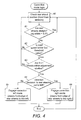
- FIG. 4 is a flow chart illustrating the steering correction system 36, which comprises a control methodology for the application of an automatic correction function to monitor the rear axle 12 and allow for the correction of any deviation from the straight ahead position by means of realigning the rear axle 12 in a safe and controlled manner.
- the system continually checks the position of rear wheels 12 60, for example by means of a position sensor, which could be of no-contact type, mounted on the rear axle 12. Feedback from the position check 60 is analysed to determined whether the rear wheels 12 are within an acceptable straight ahead position, which could for example be within ⁇ 0.5° from the straight ahead orientation 61. If the wheels are still within this range then the system begins the checking process again by repeating the position check 60.
- the rear wheels 12 are out of alignment then it is checked whether the road speed of the vehicle is below an acceptable predetermined threshold value to begin correction 62.
- the acceptable predetermined threshold value is determined based on safety and operator perception, and may for example be 30km/h. If this is not the case then the system begins the checking process again by returning to the position check 60. However, if the road speed is below the acceptable limit, then the front axle 12 is examined, for example by means of wheel position sensors, to determine whether it is within an acceptable range, which could for example be ⁇ 5° from the straight ahead orientation 63. If the front wheels 11 are not within this range, then the check sequence is started again by returning to the position check 60.
- the correction of the rear wheels 12 is only carried out whilst the front wheels 11 are close to the straight ahead orientation 63 (e.g. ⁇ 5°), i.e. whilst very close to straight-line driving, in order to minimise any operator perceptible motion of the machine which is contrary to the desired direction changes fed into the system by the operator by adjustment to a steering hand-wheel.
- the steering correction system 36 is automatic and, as such, requires no operator input, nor does it result in operator perception that the correction is being carried out.
- Figure 5 is a flow chart illustrating the error condition check 26, which is continually carried out to test for faults and to limit false positive results.
- initiation 70 of the error condition check 26 there is a wait- time 71 (e.g. 300ms) to reduce the possibility of electromagnetic interference or other 'noise' on the signal line being interpreted as an error signal condition.
- initiation 70 of the error condition check 26 there is a wait- time 71 (e.g. 300ms) to reduce the possibility of electromagnetic interference or other 'noise' on the signal line being interpreted as an error signal condition.
- It is then checked whether the sensor signals are within the working range 72, which is pre-defined as S vF for the front signal range and S vR for the rear signal range. If the signal received from the sensors are all within the acceptable ranges, then an error counter is reset to zero 73.
- the error counter is employed in order to further reduce the possibility of electromagnetic interference or other 'noise' on the signal line being interpreted as an error signal condition, by enabling the validation of multiple error signals in sequence. However, if the signals received are outside of the acceptable ranges, then the error condition counter is incremented by one 74, and it is checked whether the error counter has reached its upper predetermined limit 75, e.g. a value of 125. If the upper limit of the error counter has not been met, a sequential error condition is tested by pausing for a time delay of e.g. 8ms to ensure that the error is present and is not erroneous, after which the sensor signals are tested again 72.
- a time delay e.g. 8ms
- the upper limit of the error counter it is tested whether there is one rear wheel position sensor signal available and deemed to be working correctly, i.e. within a predetermined range 77. If one rear wheel position sensor is available, then it is possible to adjust the rear wheels 12 to the straight ahead position, and for the vehicle to continue working as a two-wheel steer vehicle only. To achieve this, the steering correction system 36 is engaged to steer the rear wheels 12 to the straight ahead orientation, in which orientation they are locked 78. However, if there is no rear wheel position sensor available (functioning within predetermined parameters), then the rear wheels 12 must immediately be locked in their current position.
- FIG. 6 shows an example hydraulic circuit which may be used to effect the present invention.
- Hydraulic fluid from a tank 50 is directed to an orbital steering unit 51 by a pump 52, which may be a unidirectional fixed displacement hydraulic pump. From the orbital steering unit, the fluid may pass to a front axle double-acting cylinder 53 via a steer-right line 54 or a steer-left line 55.
- Three valves must be engaged to enable the rear wheels 12 to steer in both directions for four-wheel steering: a 'correction-left' valve 56, a 'correction-right' valve 57, and a 'rear steer' valve 58.
- the three valves 56,57,58 are preferably four-way, two-position, direct acting, spool type, screw-in cartridge solenoid valves.
- the correction-left valve 56 and correction-right valve 57 in the energised position have port 3 open to port 4 and port 2 open to port 1, while in the de-energised position flow is allowed between port 2 and port 3 (and vice versa) while port 1 and port 4 are blocked.
- the rear-steer valve 58 in the energised position allows flow from port 3 to port 4 (and vice versa) and from port 2 to port 1 (and vice versa), while in the de-energised position allows flow from port 2 to port 3 (and vice versa) and from port 4 to port 1 (and vice versa).
- the three valves 56,57,58 are housed in a steering valve block 59.
- either the correction-left valve 56 or the correction-right valve 57 can be energised in conjunction with the rear steer valve 58 to only steer the rear wheels 12 in one direction (left or right respectively). This is provided for two reasons.
- a pilot operated check valve 62 is located in a rear-steer-left line 63 and a rear-steer-right line 68.
- the pilot operated check valve 62 requires a pilot pressure from the side where the steering effort has been initiated in order to lift a check valve off its seat and thereby allow the return of hydraulic fluid through the lines. This has the effect of only allowing a steering angle change of the rear wheels 12 to occur when initiated from the control side of the system.
- the first two modes of operation are steering left and right via two-wheel steering. In these modes, none of the correction-left valve 56, the correction-right valve 57, nor the rear-steer valve 58 is energised.
- hydraulic fluid flows from the orbital steering unit 51, through the correction-right valve 57, a first check valve 60, and the steer-left line 55 into the front axle cylinder 53, which turns the leading edge of the wheels mounted on the front axle 11 to the left. This causes hydraulic fluid to be displaced from the front axle cylinder 53 through the steer-right line 54 and the orbital steering unit 51 back into the tank 50.
- the second two modes of operation are steering left and right via four-wheel steering.
- the correction-left valve 56, the correction-right valve 57, and the rear-steer valve 68 are all energised.
- hydraulic fluid flows form the orbital steering unit 51, through the correction-right valve 57 and the rear steer valve 58, then through a pilot operated check valve 62 to a rear-steer-left line 63, which directs hydraulic fluid to the piston side 64 of a left rear cylinder 65 and the annular side 66 of a right rear cylinder 67; this has the effect of steering the leading edge of the rear wheels 12 to the right.
- Hydraulic fluid is thereby displaced from the left rear cylinder 65 and the right rear cylinder 67 into a rear-steer-right line 68, through the pilot operated check valve 62, the rear steer valve 58, both the correction-left and correction-right valves 56,57, and the steer-left line 55 into the front axle cylinder 53, which turns the leading edge of the wheels mounted on the front axle 11 to the left.
- This causes hydraulic fluid to be displaced from the front axle cylinder 53 through the steer-right line 54 and the orbital steering unit 51 back into the tank 50.
- hydraulic fluid from the orbital steering unit flows directly through the steer-right line 54 into the front axle cylinder 53, which turns the leading edge of the wheels mounted on the front axle 11 to the right.
- Hydraulic fluid is thereby displaced from the left rear cylinder 65 and the right rear cylinder 67 into the rear-steer-left line 63, through the pilot operated check valve 62, the rear steer valve 58, the correction-right valve 57 or the correction-left valve 56 and the second check valve 61, and through the orbital steering unit 51 back into the tank 50.
- the final four modes of operation comprise two correction-left modes, in which the leading edge of the rear wheels 12 are adjusted to the left, and two correction-right modes, in which the leading edge of the rear wheels 12 are adjusted to the right.
- the correction-left and right modes can only be effected during two-wheel steering.
- the correction-left valve 56 and the rear-steer valve 58 are energised, and the correction-right valve 57 is not energised.
- hydraulic fluid flows form the orbital steering unit 51, through the correction-right valve 57 and a first check valve 60, and through the steer-left line 55 into the front axle cylinder 53, which turns the leading edge of the wheels mounted on the front axle 11 to the left.
- This causes hydraulic fluid to be displaced from the front axle cylinder 53 through the steer-right line 54 and the orbital steering unit 51 back into the tank 50.
- the outcome is a two-wheel steer mode only, with no correction to the rear wheels 12.
- Hydraulic fluid is thereby displaced from the left rear cylinder 65 and the right rear cylinder 67 into the rear-steer-left line 63, through the pilot operated check valve 62, the rear steer valve 58, the correction-left valve 56 only and the second check valve 61, through the orbital steering unit 51 back into the tank 50.
- the outcome is the enablement of a four-wheel steer mode adjustment of the rear wheels 12 towards the left.
- the correction-left valve 56 is not energised, and the correction-right valve 57 and the rear-steer valve 58 are energised.
- hydraulic fluid flows from the orbital steering unit 51, through the correction-right valve 57 and the rear steer valve 58, then through the pilot operated check valve 62 to the rear-steer-left line 63, which directs hydraulic fluid to the piston side 64 of the left rear cylinder 65 and the annular side 66 of the right rear cylinder 67; this has the effect of steering the leading edge of the rear wheels 12 to the right.
- Hydraulic fluid is thereby displaced from the left rear cylinder 65 and the right rear cylinder 67 into a rear-steer-right line 68, through the pilot operated check valve 62, the rear steer valve 58, the correction-right valve 57, and the steer-left line 55 into the front axle cylinder 53, which turns the leading edge of the wheels mounted on the front axle 11 to the left.
- This causes hydraulic fluid to be displaced from the front axle cylinder 53 through the steer-right line 54 and the orbital steering unit 51 back into the tank 50.
- the outcome is the enablement of a four-wheel steer mode adjustment of the rear wheels 12 towards the right.
- FIG. 15 illustrates a gimbal apparatus 40 for use on the rear axles of the present invention.
- a hydraulic wheel motor 41 is employed on each rear wheel of the present invention, and is allowed to pivot about a steering axis 42 by application of a housing in the form of the gimbal 40, which is suspended at opposing ends a bearing arrangement 43.
- the gimbal apparatus 40 thereby enables the articulation of a flange faced fixed hydraulic wheel motor 41.
- a hydraulic hose links each of the motors 41 to a hydraulic pump, which drives the motors. This arrangement is significantly more compact than a conventional steering axle arrangement comprising a single axle which powers both wheels.
- the wheel motors 41 are inserted through the gimbal apparatus 40 from the outside of the vehicle, rotated through 90° and pulled back toward the mating face on the inside of the gimbal 40, as is illustrated in Figure 15 and Figure 16 .
- This arrangement enables the steering axis 42 to be brought closer to the hub mounting face, whilst also enabling a steering axis inclination (the angle between the steering axis and the vertical) of 3-5° to be achieved (see Figure 17 ).
- the gimbal apparatus 40 and the wheels are configured such that the steering axis 42 and the camber line (the axis passing through the centre of the tyre and wheel, perpendicular to its spin axis) intersect below the road surface, resulting in a positive scrub radius. This has the advantage that the tyre rolls as the wheel is steered, which reduces the force required for steering.
- the application of the steering system of the present invention may result in a machine which has a kerb-to-kerb turning circle which is reduced by nearly 15% when compared to the known Johnston C200 two-wheel steer machine (3760 mm compared to 4350 mm diameter of the turning circle as shown in Figure 18 .
- the wall-to-wall turning circle may be reduced by nearly 5% (4930mm compared with 5150 mm, Figure 19 ).
- the machine may follow an outside perimeter 400% smaller than the prior art machine (radius of 2.5 m compared with 10m, Figure 20 ).
- the improvement of reducing the radii of outer perimeters is by virtue of the centre of the turning arc being closer longitudinally towards the sweeping equipment.
- the improvement of the reduced inner perimeters is due to a reduced minimum turning arc of the machine.
Landscapes
- Engineering & Computer Science (AREA)
- Chemical & Material Sciences (AREA)
- Combustion & Propulsion (AREA)
- Transportation (AREA)
- Mechanical Engineering (AREA)
- Physics & Mathematics (AREA)
- Mathematical Physics (AREA)
- Theoretical Computer Science (AREA)
- Steering-Linkage Mechanisms And Four-Wheel Steering (AREA)
- Steering Control In Accordance With Driving Conditions (AREA)
Priority Applications (1)
| Application Number | Priority Date | Filing Date | Title |
|---|---|---|---|
| PL12172834T PL2537734T3 (pl) | 2011-06-20 | 2012-06-20 | Układ kierowniczy |
Applications Claiming Priority (1)
| Application Number | Priority Date | Filing Date | Title |
|---|---|---|---|
| GBGB1110434.6A GB201110434D0 (en) | 2011-06-20 | 2011-06-20 | Steering system |
Publications (2)
| Publication Number | Publication Date |
|---|---|
| EP2537734A1 true EP2537734A1 (de) | 2012-12-26 |
| EP2537734B1 EP2537734B1 (de) | 2014-11-12 |
Family
ID=44454358
Family Applications (1)
| Application Number | Title | Priority Date | Filing Date |
|---|---|---|---|
| EP12172834.9A Active EP2537734B1 (de) | 2011-06-20 | 2012-06-20 | Servolenksystem |
Country Status (5)
| Country | Link |
|---|---|
| EP (1) | EP2537734B1 (de) |
| DK (1) | DK2537734T3 (de) |
| ES (1) | ES2524904T3 (de) |
| GB (1) | GB201110434D0 (de) |
| PL (1) | PL2537734T3 (de) |
Citations (6)
| Publication number | Priority date | Publication date | Assignee | Title |
|---|---|---|---|---|
| DE3517079A1 (de) | 1985-05-11 | 1986-11-13 | Schörling GmbH & Co Waggonbau, 3000 Hannover | Selbstaufnehmendes kehrfahrzeug |
| EP0300774A2 (de) * | 1987-07-21 | 1989-01-25 | J.C. Bamford Excavators Limited | Materialien-Förderungsfahrzeug |
| WO1991019048A1 (en) | 1990-06-08 | 1991-12-12 | Schmidt Winterdienst- Und Kommunaltechnik Gmbh | Cleaning and other vehicles |
| US5111901A (en) * | 1989-08-08 | 1992-05-12 | Oshkosh Truck Company | All wheel steering system |
| US5238077A (en) * | 1989-06-23 | 1993-08-24 | Trw Inc. | Method and apparatus for steering a vehicle |
| EP1612335A2 (de) | 2004-06-29 | 2006-01-04 | Schmidt Holding GmbH | Selbstfahrende Kehrmaschine |
-
2011
- 2011-06-20 GB GBGB1110434.6A patent/GB201110434D0/en not_active Ceased
-
2012
- 2012-06-20 PL PL12172834T patent/PL2537734T3/pl unknown
- 2012-06-20 DK DK12172834.9T patent/DK2537734T3/en active
- 2012-06-20 ES ES12172834.9T patent/ES2524904T3/es active Active
- 2012-06-20 EP EP12172834.9A patent/EP2537734B1/de active Active
Patent Citations (6)
| Publication number | Priority date | Publication date | Assignee | Title |
|---|---|---|---|---|
| DE3517079A1 (de) | 1985-05-11 | 1986-11-13 | Schörling GmbH & Co Waggonbau, 3000 Hannover | Selbstaufnehmendes kehrfahrzeug |
| EP0300774A2 (de) * | 1987-07-21 | 1989-01-25 | J.C. Bamford Excavators Limited | Materialien-Förderungsfahrzeug |
| US5238077A (en) * | 1989-06-23 | 1993-08-24 | Trw Inc. | Method and apparatus for steering a vehicle |
| US5111901A (en) * | 1989-08-08 | 1992-05-12 | Oshkosh Truck Company | All wheel steering system |
| WO1991019048A1 (en) | 1990-06-08 | 1991-12-12 | Schmidt Winterdienst- Und Kommunaltechnik Gmbh | Cleaning and other vehicles |
| EP1612335A2 (de) | 2004-06-29 | 2006-01-04 | Schmidt Holding GmbH | Selbstfahrende Kehrmaschine |
Also Published As
| Publication number | Publication date |
|---|---|
| EP2537734B1 (de) | 2014-11-12 |
| PL2537734T3 (pl) | 2015-04-30 |
| DK2537734T3 (en) | 2014-12-08 |
| GB201110434D0 (en) | 2011-08-03 |
| ES2524904T3 (es) | 2014-12-15 |
Similar Documents
| Publication | Publication Date | Title |
|---|---|---|
| US9051711B2 (en) | Path detection-based steering command filtering method for motor grader automatic articulation feature | |
| US8548680B2 (en) | Steering system with automated articulation control | |
| US7252299B2 (en) | Steering system for crane | |
| EP2944540B1 (de) | Drehsystem und schwerlastradfahrzeug mit unabhängiger aufhängung | |
| EP1643041B1 (de) | Lenkbetätigungssystem für Radlader. | |
| JP2015117005A (ja) | ステアリング装置 | |
| US7530921B2 (en) | Apparatus and method providing neutral safeing for the propulsion system of an agricultural windrower | |
| JP3464325B2 (ja) | 作業車の転舵装置 | |
| EP2537734B1 (de) | Servolenksystem | |
| JP3238275B2 (ja) | 四輪駆動車 | |
| CN114056423B (zh) | 车辆转向控制系统和具有其的车辆 | |
| JPH0569850A (ja) | 四輪操舵車両の操舵システム | |
| JP2528460B2 (ja) | 車両の4輪操舵装置 | |
| SE545191C2 (en) | Control device and method for controlling a tag axle steering system | |
| JP2599944B2 (ja) | 作業用車両の自動操向装置 | |
| JP3005151B2 (ja) | ビーム光誘導式作業車の走行制御装置 | |
| JPH0730419Y2 (ja) | 移動農機の回向装置 | |
| CN115771561A (zh) | 一种双向驾驶四轮多功能液压控制方法 | |
| JPH0492907A (ja) | 芝刈り作業車の操向制御装置 | |
| JPH0787807A (ja) | 作業車 | |
| JPH0344033B2 (de) | ||
| JPS63276404A (ja) | 自動走行作業車用の境界検出装置 | |
| JPS63270283A (ja) | 車両の4輪操舵装置 | |
| JPS62181963A (ja) | 車両の4輪操舵装置 | |
| JPH03153466A (ja) | 車両の後輪操舵装置 |
Legal Events
| Date | Code | Title | Description |
|---|---|---|---|
| PUAI | Public reference made under article 153(3) epc to a published international application that has entered the european phase |
Free format text: ORIGINAL CODE: 0009012 |
|
| AK | Designated contracting states |
Kind code of ref document: A1 Designated state(s): AL AT BE BG CH CY CZ DE DK EE ES FI FR GB GR HR HU IE IS IT LI LT LU LV MC MK MT NL NO PL PT RO RS SE SI SK SM TR |
|
| AX | Request for extension of the european patent |
Extension state: BA ME |
|
| 17P | Request for examination filed |
Effective date: 20130424 |
|
| GRAP | Despatch of communication of intention to grant a patent |
Free format text: ORIGINAL CODE: EPIDOSNIGR1 |
|
| INTG | Intention to grant announced |
Effective date: 20140605 |
|
| GRAS | Grant fee paid |
Free format text: ORIGINAL CODE: EPIDOSNIGR3 |
|
| GRAA | (expected) grant |
Free format text: ORIGINAL CODE: 0009210 |
|
| AK | Designated contracting states |
Kind code of ref document: B1 Designated state(s): AL AT BE BG CH CY CZ DE DK EE ES FI FR GB GR HR HU IE IS IT LI LT LU LV MC MK MT NL NO PL PT RO RS SE SI SK SM TR |
|
| REG | Reference to a national code |
Ref country code: GB Ref legal event code: FG4D |
|
| REG | Reference to a national code |
Ref country code: CH Ref legal event code: EP |
|
| REG | Reference to a national code |
Ref country code: AT Ref legal event code: REF Ref document number: 695543 Country of ref document: AT Kind code of ref document: T Effective date: 20141115 |
|
| REG | Reference to a national code |
Ref country code: CH Ref legal event code: NV Representative=s name: KIRKER AND CIE S.A., CH |
|
| REG | Reference to a national code |
Ref country code: IE Ref legal event code: FG4D |
|
| REG | Reference to a national code |
Ref country code: DK Ref legal event code: T3 Effective date: 20141201 |
|
| REG | Reference to a national code |
Ref country code: ES Ref legal event code: FG2A Ref document number: 2524904 Country of ref document: ES Kind code of ref document: T3 Effective date: 20141215 |
|
| REG | Reference to a national code |
Ref country code: DE Ref legal event code: R096 Ref document number: 602012003731 Country of ref document: DE Effective date: 20141224 |
|
| REG | Reference to a national code |
Ref country code: NL Ref legal event code: T3 |
|
| REG | Reference to a national code |
Ref country code: SE Ref legal event code: TRGR |
|
| PG25 | Lapsed in a contracting state [announced via postgrant information from national office to epo] |
Ref country code: PT Free format text: LAPSE BECAUSE OF FAILURE TO SUBMIT A TRANSLATION OF THE DESCRIPTION OR TO PAY THE FEE WITHIN THE PRESCRIBED TIME-LIMIT Effective date: 20150312 Ref country code: NO Free format text: LAPSE BECAUSE OF FAILURE TO SUBMIT A TRANSLATION OF THE DESCRIPTION OR TO PAY THE FEE WITHIN THE PRESCRIBED TIME-LIMIT Effective date: 20150212 Ref country code: IS Free format text: LAPSE BECAUSE OF FAILURE TO SUBMIT A TRANSLATION OF THE DESCRIPTION OR TO PAY THE FEE WITHIN THE PRESCRIBED TIME-LIMIT Effective date: 20150312 Ref country code: LT Free format text: LAPSE BECAUSE OF FAILURE TO SUBMIT A TRANSLATION OF THE DESCRIPTION OR TO PAY THE FEE WITHIN THE PRESCRIBED TIME-LIMIT Effective date: 20141112 Ref country code: FI Free format text: LAPSE BECAUSE OF FAILURE TO SUBMIT A TRANSLATION OF THE DESCRIPTION OR TO PAY THE FEE WITHIN THE PRESCRIBED TIME-LIMIT Effective date: 20141112 |
|
| REG | Reference to a national code |
Ref country code: PL Ref legal event code: T3 |
|
| PG25 | Lapsed in a contracting state [announced via postgrant information from national office to epo] |
Ref country code: GR Free format text: LAPSE BECAUSE OF FAILURE TO SUBMIT A TRANSLATION OF THE DESCRIPTION OR TO PAY THE FEE WITHIN THE PRESCRIBED TIME-LIMIT Effective date: 20150213 Ref country code: LV Free format text: LAPSE BECAUSE OF FAILURE TO SUBMIT A TRANSLATION OF THE DESCRIPTION OR TO PAY THE FEE WITHIN THE PRESCRIBED TIME-LIMIT Effective date: 20141112 Ref country code: RS Free format text: LAPSE BECAUSE OF FAILURE TO SUBMIT A TRANSLATION OF THE DESCRIPTION OR TO PAY THE FEE WITHIN THE PRESCRIBED TIME-LIMIT Effective date: 20141112 Ref country code: CY Free format text: LAPSE BECAUSE OF FAILURE TO SUBMIT A TRANSLATION OF THE DESCRIPTION OR TO PAY THE FEE WITHIN THE PRESCRIBED TIME-LIMIT Effective date: 20141112 Ref country code: HR Free format text: LAPSE BECAUSE OF FAILURE TO SUBMIT A TRANSLATION OF THE DESCRIPTION OR TO PAY THE FEE WITHIN THE PRESCRIBED TIME-LIMIT Effective date: 20141112 |
|
| PG25 | Lapsed in a contracting state [announced via postgrant information from national office to epo] |
Ref country code: SK Free format text: LAPSE BECAUSE OF FAILURE TO SUBMIT A TRANSLATION OF THE DESCRIPTION OR TO PAY THE FEE WITHIN THE PRESCRIBED TIME-LIMIT Effective date: 20141112 Ref country code: EE Free format text: LAPSE BECAUSE OF FAILURE TO SUBMIT A TRANSLATION OF THE DESCRIPTION OR TO PAY THE FEE WITHIN THE PRESCRIBED TIME-LIMIT Effective date: 20141112 Ref country code: RO Free format text: LAPSE BECAUSE OF FAILURE TO SUBMIT A TRANSLATION OF THE DESCRIPTION OR TO PAY THE FEE WITHIN THE PRESCRIBED TIME-LIMIT Effective date: 20141112 |
|
| REG | Reference to a national code |
Ref country code: DE Ref legal event code: R097 Ref document number: 602012003731 Country of ref document: DE |
|
| PLBE | No opposition filed within time limit |
Free format text: ORIGINAL CODE: 0009261 |
|
| STAA | Information on the status of an ep patent application or granted ep patent |
Free format text: STATUS: NO OPPOSITION FILED WITHIN TIME LIMIT |
|
| 26N | No opposition filed |
Effective date: 20150813 |
|
| PG25 | Lapsed in a contracting state [announced via postgrant information from national office to epo] |
Ref country code: MC Free format text: LAPSE BECAUSE OF FAILURE TO SUBMIT A TRANSLATION OF THE DESCRIPTION OR TO PAY THE FEE WITHIN THE PRESCRIBED TIME-LIMIT Effective date: 20141112 |
|
| PG25 | Lapsed in a contracting state [announced via postgrant information from national office to epo] |
Ref country code: SI Free format text: LAPSE BECAUSE OF FAILURE TO SUBMIT A TRANSLATION OF THE DESCRIPTION OR TO PAY THE FEE WITHIN THE PRESCRIBED TIME-LIMIT Effective date: 20141112 Ref country code: LU Free format text: LAPSE BECAUSE OF FAILURE TO SUBMIT A TRANSLATION OF THE DESCRIPTION OR TO PAY THE FEE WITHIN THE PRESCRIBED TIME-LIMIT Effective date: 20150620 |
|
| REG | Reference to a national code |
Ref country code: IE Ref legal event code: MM4A |
|
| PG25 | Lapsed in a contracting state [announced via postgrant information from national office to epo] |
Ref country code: IE Free format text: LAPSE BECAUSE OF NON-PAYMENT OF DUE FEES Effective date: 20150620 |
|
| REG | Reference to a national code |
Ref country code: FR Ref legal event code: PLFP Year of fee payment: 5 |
|
| PG25 | Lapsed in a contracting state [announced via postgrant information from national office to epo] |
Ref country code: MT Free format text: LAPSE BECAUSE OF FAILURE TO SUBMIT A TRANSLATION OF THE DESCRIPTION OR TO PAY THE FEE WITHIN THE PRESCRIBED TIME-LIMIT Effective date: 20141112 |
|
| PG25 | Lapsed in a contracting state [announced via postgrant information from national office to epo] |
Ref country code: SM Free format text: LAPSE BECAUSE OF FAILURE TO SUBMIT A TRANSLATION OF THE DESCRIPTION OR TO PAY THE FEE WITHIN THE PRESCRIBED TIME-LIMIT Effective date: 20141112 Ref country code: HU Free format text: LAPSE BECAUSE OF FAILURE TO SUBMIT A TRANSLATION OF THE DESCRIPTION OR TO PAY THE FEE WITHIN THE PRESCRIBED TIME-LIMIT; INVALID AB INITIO Effective date: 20120620 Ref country code: BG Free format text: LAPSE BECAUSE OF FAILURE TO SUBMIT A TRANSLATION OF THE DESCRIPTION OR TO PAY THE FEE WITHIN THE PRESCRIBED TIME-LIMIT Effective date: 20141112 |
|
| REG | Reference to a national code |
Ref country code: FR Ref legal event code: PLFP Year of fee payment: 6 |
|
| PG25 | Lapsed in a contracting state [announced via postgrant information from national office to epo] |
Ref country code: BE Free format text: LAPSE BECAUSE OF FAILURE TO SUBMIT A TRANSLATION OF THE DESCRIPTION OR TO PAY THE FEE WITHIN THE PRESCRIBED TIME-LIMIT Effective date: 20141112 |
|
| REG | Reference to a national code |
Ref country code: FR Ref legal event code: PLFP Year of fee payment: 7 |
|
| PG25 | Lapsed in a contracting state [announced via postgrant information from national office to epo] |
Ref country code: MK Free format text: LAPSE BECAUSE OF FAILURE TO SUBMIT A TRANSLATION OF THE DESCRIPTION OR TO PAY THE FEE WITHIN THE PRESCRIBED TIME-LIMIT Effective date: 20141112 |
|
| PG25 | Lapsed in a contracting state [announced via postgrant information from national office to epo] |
Ref country code: AL Free format text: LAPSE BECAUSE OF FAILURE TO SUBMIT A TRANSLATION OF THE DESCRIPTION OR TO PAY THE FEE WITHIN THE PRESCRIBED TIME-LIMIT Effective date: 20141112 |
|
| REG | Reference to a national code |
Ref country code: DE Ref legal event code: R081 Ref document number: 602012003731 Country of ref document: DE Owner name: BUCHER MUNICIPAL LTD., DORKING, GB Free format text: FORMER OWNER: JOHNSTON SWEEPERS LTD., DORKING, SURREY, GB |
|
| REG | Reference to a national code |
Ref country code: CH Ref legal event code: PFA Owner name: BUCHER MUNICIPAL LIMITED, GB Free format text: FORMER OWNER: JOHNSTON SWEEPERS LIMITED, GB |
|
| REG | Reference to a national code |
Ref country code: ES Ref legal event code: PC2A Owner name: BUCHER MUNICIPAL LIMITED Effective date: 20201027 |
|
| REG | Reference to a national code |
Ref country code: NL Ref legal event code: HC Owner name: BUCHER MUNICIPAL LIMITED; GB Free format text: DETAILS ASSIGNMENT: CHANGE OF OWNER(S), CHANGE OF OWNER(S) NAME; FORMER OWNER NAME: JOHNSTON SWEEPERS LIMITED Effective date: 20201013 |
|
| REG | Reference to a national code |
Ref country code: AT Ref legal event code: HC Ref document number: 695543 Country of ref document: AT Kind code of ref document: T Owner name: BUCHER MUNICIPAL LIMITED, GB Effective date: 20210302 |
|
| PGFP | Annual fee paid to national office [announced via postgrant information from national office to epo] |
Ref country code: NL Payment date: 20230616 Year of fee payment: 12 Ref country code: FR Payment date: 20230619 Year of fee payment: 12 Ref country code: DK Payment date: 20230615 Year of fee payment: 12 Ref country code: DE Payment date: 20230621 Year of fee payment: 12 Ref country code: CZ Payment date: 20230523 Year of fee payment: 12 |
|
| PGFP | Annual fee paid to national office [announced via postgrant information from national office to epo] |
Ref country code: TR Payment date: 20230607 Year of fee payment: 12 Ref country code: SE Payment date: 20230616 Year of fee payment: 12 Ref country code: PL Payment date: 20230523 Year of fee payment: 12 Ref country code: AT Payment date: 20230621 Year of fee payment: 12 |
|
| PGFP | Annual fee paid to national office [announced via postgrant information from national office to epo] |
Ref country code: IT Payment date: 20230620 Year of fee payment: 12 Ref country code: GB Payment date: 20230619 Year of fee payment: 12 Ref country code: ES Payment date: 20230703 Year of fee payment: 12 Ref country code: CH Payment date: 20230702 Year of fee payment: 12 |