EP2537629B1 - Equipment for the exchange of replaceable components in machine tools - Google Patents
Equipment for the exchange of replaceable components in machine tools Download PDFInfo
- Publication number
- EP2537629B1 EP2537629B1 EP10846007.2A EP10846007A EP2537629B1 EP 2537629 B1 EP2537629 B1 EP 2537629B1 EP 10846007 A EP10846007 A EP 10846007A EP 2537629 B1 EP2537629 B1 EP 2537629B1
- Authority
- EP
- European Patent Office
- Prior art keywords
- category
- storage
- equipment
- manipulator
- replaceable
- Prior art date
- Legal status (The legal status is an assumption and is not a legal conclusion. Google has not performed a legal analysis and makes no representation as to the accuracy of the status listed.)
- Active
Links
- 238000003860 storage Methods 0.000 claims description 85
- 230000008859 change Effects 0.000 claims description 41
- 238000003754 machining Methods 0.000 claims description 23
- 238000004873 anchoring Methods 0.000 claims description 6
- 238000000034 method Methods 0.000 claims description 5
- 230000003068 static effect Effects 0.000 claims description 5
- 238000004590 computer program Methods 0.000 claims 1
- 230000008901 benefit Effects 0.000 description 10
- 230000008878 coupling Effects 0.000 description 4
- 238000010168 coupling process Methods 0.000 description 4
- 238000005859 coupling reaction Methods 0.000 description 4
- 238000004519 manufacturing process Methods 0.000 description 4
- 230000000295 complement effect Effects 0.000 description 3
- 238000012423 maintenance Methods 0.000 description 2
- 238000002360 preparation method Methods 0.000 description 2
- 230000008569 process Effects 0.000 description 2
- 238000004140 cleaning Methods 0.000 description 1
- 239000000470 constituent Substances 0.000 description 1
- 238000000151 deposition Methods 0.000 description 1
- 230000000694 effects Effects 0.000 description 1
- 230000007246 mechanism Effects 0.000 description 1
- 230000003252 repetitive effect Effects 0.000 description 1
- 238000004904 shortening Methods 0.000 description 1
- 230000009897 systematic effect Effects 0.000 description 1
Images


Classifications
-
- B—PERFORMING OPERATIONS; TRANSPORTING
- B23—MACHINE TOOLS; METAL-WORKING NOT OTHERWISE PROVIDED FOR
- B23Q—DETAILS, COMPONENTS, OR ACCESSORIES FOR MACHINE TOOLS, e.g. ARRANGEMENTS FOR COPYING OR CONTROLLING; MACHINE TOOLS IN GENERAL CHARACTERISED BY THE CONSTRUCTION OF PARTICULAR DETAILS OR COMPONENTS; COMBINATIONS OR ASSOCIATIONS OF METAL-WORKING MACHINES, NOT DIRECTED TO A PARTICULAR RESULT
- B23Q3/00—Devices holding, supporting, or positioning work or tools, of a kind normally removable from the machine
- B23Q3/155—Arrangements for automatic insertion or removal of tools, e.g. combined with manual handling
- B23Q3/1552—Arrangements for automatic insertion or removal of tools, e.g. combined with manual handling parts of devices for automatically inserting or removing tools
- B23Q3/15526—Storage devices; Drive mechanisms therefor
- B23Q3/15536—Non-rotary fixed racks
-
- B—PERFORMING OPERATIONS; TRANSPORTING
- B23—MACHINE TOOLS; METAL-WORKING NOT OTHERWISE PROVIDED FOR
- B23B—TURNING; BORING
- B23B3/00—General-purpose turning-machines or devices, e.g. centre lathes with feed rod and lead screw; Sets of turning-machines
- B23B3/08—Turning-machines characterised by the use of faceplates
- B23B3/10—Turning-machines characterised by the use of faceplates with the faceplate horizontal, i.e. vertical boring and turning machines
-
- B—PERFORMING OPERATIONS; TRANSPORTING
- B23—MACHINE TOOLS; METAL-WORKING NOT OTHERWISE PROVIDED FOR
- B23Q—DETAILS, COMPONENTS, OR ACCESSORIES FOR MACHINE TOOLS, e.g. ARRANGEMENTS FOR COPYING OR CONTROLLING; MACHINE TOOLS IN GENERAL CHARACTERISED BY THE CONSTRUCTION OF PARTICULAR DETAILS OR COMPONENTS; COMBINATIONS OR ASSOCIATIONS OF METAL-WORKING MACHINES, NOT DIRECTED TO A PARTICULAR RESULT
- B23Q1/00—Members which are comprised in the general build-up of a form of machine, particularly relatively large fixed members
- B23Q1/01—Frames, beds, pillars or like members; Arrangement of ways
- B23Q1/012—Portals
-
- B—PERFORMING OPERATIONS; TRANSPORTING
- B23—MACHINE TOOLS; METAL-WORKING NOT OTHERWISE PROVIDED FOR
- B23Q—DETAILS, COMPONENTS, OR ACCESSORIES FOR MACHINE TOOLS, e.g. ARRANGEMENTS FOR COPYING OR CONTROLLING; MACHINE TOOLS IN GENERAL CHARACTERISED BY THE CONSTRUCTION OF PARTICULAR DETAILS OR COMPONENTS; COMBINATIONS OR ASSOCIATIONS OF METAL-WORKING MACHINES, NOT DIRECTED TO A PARTICULAR RESULT
- B23Q11/00—Accessories fitted to machine tools for keeping tools or parts of the machine in good working condition or for cooling work; Safety devices specially combined with or arranged in, or specially adapted for use in connection with, machine tools
- B23Q11/08—Protective coverings for parts of machine tools; Splash guards
-
- B—PERFORMING OPERATIONS; TRANSPORTING
- B23—MACHINE TOOLS; METAL-WORKING NOT OTHERWISE PROVIDED FOR
- B23Q—DETAILS, COMPONENTS, OR ACCESSORIES FOR MACHINE TOOLS, e.g. ARRANGEMENTS FOR COPYING OR CONTROLLING; MACHINE TOOLS IN GENERAL CHARACTERISED BY THE CONSTRUCTION OF PARTICULAR DETAILS OR COMPONENTS; COMBINATIONS OR ASSOCIATIONS OF METAL-WORKING MACHINES, NOT DIRECTED TO A PARTICULAR RESULT
- B23Q3/00—Devices holding, supporting, or positioning work or tools, of a kind normally removable from the machine
- B23Q3/155—Arrangements for automatic insertion or removal of tools, e.g. combined with manual handling
- B23Q3/1552—Arrangements for automatic insertion or removal of tools, e.g. combined with manual handling parts of devices for automatically inserting or removing tools
- B23Q3/15526—Storage devices; Drive mechanisms therefor
- B23Q3/15539—Plural magazines, e.g. involving tool transfer from one magazine to another
-
- B—PERFORMING OPERATIONS; TRANSPORTING
- B23—MACHINE TOOLS; METAL-WORKING NOT OTHERWISE PROVIDED FOR
- B23Q—DETAILS, COMPONENTS, OR ACCESSORIES FOR MACHINE TOOLS, e.g. ARRANGEMENTS FOR COPYING OR CONTROLLING; MACHINE TOOLS IN GENERAL CHARACTERISED BY THE CONSTRUCTION OF PARTICULAR DETAILS OR COMPONENTS; COMBINATIONS OR ASSOCIATIONS OF METAL-WORKING MACHINES, NOT DIRECTED TO A PARTICULAR RESULT
- B23Q3/00—Devices holding, supporting, or positioning work or tools, of a kind normally removable from the machine
- B23Q3/155—Arrangements for automatic insertion or removal of tools, e.g. combined with manual handling
- B23Q3/1552—Arrangements for automatic insertion or removal of tools, e.g. combined with manual handling parts of devices for automatically inserting or removing tools
- B23Q3/15553—Tensioning devices or tool holders, e.g. grippers
-
- B—PERFORMING OPERATIONS; TRANSPORTING
- B23—MACHINE TOOLS; METAL-WORKING NOT OTHERWISE PROVIDED FOR
- B23Q—DETAILS, COMPONENTS, OR ACCESSORIES FOR MACHINE TOOLS, e.g. ARRANGEMENTS FOR COPYING OR CONTROLLING; MACHINE TOOLS IN GENERAL CHARACTERISED BY THE CONSTRUCTION OF PARTICULAR DETAILS OR COMPONENTS; COMBINATIONS OR ASSOCIATIONS OF METAL-WORKING MACHINES, NOT DIRECTED TO A PARTICULAR RESULT
- B23Q3/00—Devices holding, supporting, or positioning work or tools, of a kind normally removable from the machine
- B23Q3/155—Arrangements for automatic insertion or removal of tools, e.g. combined with manual handling
- B23Q3/157—Arrangements for automatic insertion or removal of tools, e.g. combined with manual handling of rotary tools
- B23Q3/15706—Arrangements for automatic insertion or removal of tools, e.g. combined with manual handling of rotary tools a single tool being inserted in a spindle directly from a storage device, i.e. without using transfer devices
-
- B—PERFORMING OPERATIONS; TRANSPORTING
- B23—MACHINE TOOLS; METAL-WORKING NOT OTHERWISE PROVIDED FOR
- B23Q—DETAILS, COMPONENTS, OR ACCESSORIES FOR MACHINE TOOLS, e.g. ARRANGEMENTS FOR COPYING OR CONTROLLING; MACHINE TOOLS IN GENERAL CHARACTERISED BY THE CONSTRUCTION OF PARTICULAR DETAILS OR COMPONENTS; COMBINATIONS OR ASSOCIATIONS OF METAL-WORKING MACHINES, NOT DIRECTED TO A PARTICULAR RESULT
- B23Q3/00—Devices holding, supporting, or positioning work or tools, of a kind normally removable from the machine
- B23Q3/155—Arrangements for automatic insertion or removal of tools, e.g. combined with manual handling
- B23Q3/1552—Arrangements for automatic insertion or removal of tools, e.g. combined with manual handling parts of devices for automatically inserting or removing tools
- B23Q3/1554—Transfer mechanisms, e.g. tool gripping arms; Drive mechanisms therefore
- B23Q2003/155414—Transfer mechanisms, e.g. tool gripping arms; Drive mechanisms therefore the transfer mechanism comprising two or more grippers
- B23Q2003/155418—Transfer mechanisms, e.g. tool gripping arms; Drive mechanisms therefore the transfer mechanism comprising two or more grippers the grippers moving together
-
- B—PERFORMING OPERATIONS; TRANSPORTING
- B23—MACHINE TOOLS; METAL-WORKING NOT OTHERWISE PROVIDED FOR
- B23Q—DETAILS, COMPONENTS, OR ACCESSORIES FOR MACHINE TOOLS, e.g. ARRANGEMENTS FOR COPYING OR CONTROLLING; MACHINE TOOLS IN GENERAL CHARACTERISED BY THE CONSTRUCTION OF PARTICULAR DETAILS OR COMPONENTS; COMBINATIONS OR ASSOCIATIONS OF METAL-WORKING MACHINES, NOT DIRECTED TO A PARTICULAR RESULT
- B23Q3/00—Devices holding, supporting, or positioning work or tools, of a kind normally removable from the machine
- B23Q3/155—Arrangements for automatic insertion or removal of tools, e.g. combined with manual handling
- B23Q3/1552—Arrangements for automatic insertion or removal of tools, e.g. combined with manual handling parts of devices for automatically inserting or removing tools
- B23Q3/1554—Transfer mechanisms, e.g. tool gripping arms; Drive mechanisms therefore
- B23Q2003/155414—Transfer mechanisms, e.g. tool gripping arms; Drive mechanisms therefore the transfer mechanism comprising two or more grippers
- B23Q2003/155425—Transfer mechanisms, e.g. tool gripping arms; Drive mechanisms therefore the transfer mechanism comprising two or more grippers pivotable
- B23Q2003/155428—Transfer mechanisms, e.g. tool gripping arms; Drive mechanisms therefore the transfer mechanism comprising two or more grippers pivotable about a common axis
-
- B—PERFORMING OPERATIONS; TRANSPORTING
- B23—MACHINE TOOLS; METAL-WORKING NOT OTHERWISE PROVIDED FOR
- B23Q—DETAILS, COMPONENTS, OR ACCESSORIES FOR MACHINE TOOLS, e.g. ARRANGEMENTS FOR COPYING OR CONTROLLING; MACHINE TOOLS IN GENERAL CHARACTERISED BY THE CONSTRUCTION OF PARTICULAR DETAILS OR COMPONENTS; COMBINATIONS OR ASSOCIATIONS OF METAL-WORKING MACHINES, NOT DIRECTED TO A PARTICULAR RESULT
- B23Q3/00—Devices holding, supporting, or positioning work or tools, of a kind normally removable from the machine
- B23Q3/155—Arrangements for automatic insertion or removal of tools, e.g. combined with manual handling
- B23Q3/1552—Arrangements for automatic insertion or removal of tools, e.g. combined with manual handling parts of devices for automatically inserting or removing tools
- B23Q3/1554—Transfer mechanisms, e.g. tool gripping arms; Drive mechanisms therefore
- B23Q2003/155414—Transfer mechanisms, e.g. tool gripping arms; Drive mechanisms therefore the transfer mechanism comprising two or more grippers
- B23Q2003/155453—Transfer mechanisms, e.g. tool gripping arms; Drive mechanisms therefore the transfer mechanism comprising two or more grippers including different gripper configurations for holding differently-configured tools
-
- B—PERFORMING OPERATIONS; TRANSPORTING
- B23—MACHINE TOOLS; METAL-WORKING NOT OTHERWISE PROVIDED FOR
- B23Q—DETAILS, COMPONENTS, OR ACCESSORIES FOR MACHINE TOOLS, e.g. ARRANGEMENTS FOR COPYING OR CONTROLLING; MACHINE TOOLS IN GENERAL CHARACTERISED BY THE CONSTRUCTION OF PARTICULAR DETAILS OR COMPONENTS; COMBINATIONS OR ASSOCIATIONS OF METAL-WORKING MACHINES, NOT DIRECTED TO A PARTICULAR RESULT
- B23Q3/00—Devices holding, supporting, or positioning work or tools, of a kind normally removable from the machine
- B23Q3/155—Arrangements for automatic insertion or removal of tools, e.g. combined with manual handling
- B23Q3/15503—Processes characterized by special sequencing of operations or the like, e.g. for optimizing tool changing time or capacity in tool storage
-
- Y—GENERAL TAGGING OF NEW TECHNOLOGICAL DEVELOPMENTS; GENERAL TAGGING OF CROSS-SECTIONAL TECHNOLOGIES SPANNING OVER SEVERAL SECTIONS OF THE IPC; TECHNICAL SUBJECTS COVERED BY FORMER USPC CROSS-REFERENCE ART COLLECTIONS [XRACs] AND DIGESTS
- Y10—TECHNICAL SUBJECTS COVERED BY FORMER USPC
- Y10S—TECHNICAL SUBJECTS COVERED BY FORMER USPC CROSS-REFERENCE ART COLLECTIONS [XRACs] AND DIGESTS
- Y10S483/00—Tool changing
- Y10S483/902—Tool grippers
-
- Y—GENERAL TAGGING OF NEW TECHNOLOGICAL DEVELOPMENTS; GENERAL TAGGING OF CROSS-SECTIONAL TECHNOLOGIES SPANNING OVER SEVERAL SECTIONS OF THE IPC; TECHNICAL SUBJECTS COVERED BY FORMER USPC CROSS-REFERENCE ART COLLECTIONS [XRACs] AND DIGESTS
- Y10—TECHNICAL SUBJECTS COVERED BY FORMER USPC
- Y10T—TECHNICAL SUBJECTS COVERED BY FORMER US CLASSIFICATION
- Y10T483/00—Tool changing
- Y10T483/17—Tool changing including machine tool or component
Definitions
- the present invention equipment for the exchange of replaceable components in machine tools relates, as the title indicates, to equipment for the automatic exchange of different components of different categories (machining heads, tool holders and tools) in machine tools.
- the purpose of the equipment is to allow, in a machine tool for example a vertical lathe or the like, the exchange of replaceable components of various categories therein, whether they are heads, tool holders or tools, for which said equipment essentially comprises a unified static storage, where all the replaceable components of the different categories are stored, and a single piece of manipulating equipment for said components automated and controlled by a control system, which is provided with freedom of movements and has at least one manipulator with gripping means suitable for gripping said replaceable components of different categories, such that said manipulator is capable of the movement, exchange and positioning thereof between the main axis or ram of the machine tool and the mentioned storage.
- the field of application of the present invention is comprised within the technical sector of the industry dedicated to manufacturing machine tools, as well as equipment, machines and devices for the change of heads, tool holders and replaceable tools in machine tools.
- manipulating equipment or robots which, by means of two clamps, exclusively jaw and transport tools from a storage to the main axis or ram of a machine tool and vice versa, their application being limited solely to the change of tools.
- This fact involves a drawback since in many machine tools it is necessary to not only carry out the change of tools for performing different operations, but it is also necessary to carry out the change of the head or tool holder, which operations must be performed automatically by means of other independent equipment or manually, with the consequent loss of time that this involves.
- These types of devices are described in the state of the art documents numbers DE29821047U1 , EP01985411A1 , EP0128487A1 and GB2075893A .
- Prior art document DE29821047U1 describes an equipment for the change in machine tools with a ram of replaceable components with a single unified single static storage in which all the replaceable components are located and a single piece of manipulating equipment for said components, automated and controlled by a control system, said manipulating equipment having a single manipulator for the movement, exchange and positioning of the replaceable components between the ram of the machine tool and the storage.
- This document only refers to the change of tools, not to the change of tools and head or tool holders, as components of different categories, being provided with two different gripping devices in the manipulator for reducing the replacement time of components of different categories.
- an objective of the present invention is to provide to the state of the art a single piece of equipment for the movement, exchange and positioning of replaceable components of different categories in a machine tool, heads, tool holders as well as tools, in which the advantages of the known systems are incorporated and the aforementioned drawbacks are prevented, it being necessary to point out that the applicant does not know of the existence of any equipment having technical, structural and constituent characteristics similar to those of the equipment which is described in the present application.
- the equipment for the change of replaceable components of different categories thus allows carrying out not only the change of tools in a machine tool, but it also performs the change of heads or tool holders, when it is necessary.
- the equipment of the invention is advantageously capable of carrying out the change or replacement of tools in the same run or cycle of the manipulating equipment or robot in which the replacement of a head or tool holder is carried out, allowing to reduce the movements and operations of the manipulating equipment and, therefore, the time invested when the replacement of a head is necessary, prior to the change or replacement of one tool or more.
- the manipulating equipment located on an independent platform of the machine tool, is placed in an enclosure isolated from the operators while the machine tool is operating, and from said platform the manipulating equipment or robot accesses rotating around a vertical axis or moving longitudinally, allowing the replacement of a tool or head in the single changing position in the horizontal movement axis of the ram, but not in the vertical movement axis.
- the ram is accessed by means of the intermediate rigid arms of a fixed length of the manipulating equipment at the free end of which the manipulator is located, which end is opposite the base of the manipulating equipment located in the previous independent platform.
- Said manipulator comprises at least one first gripping device for a first category of replaceable components, for example heads or tool holders,and at least one second gripping device for a second category of components, for example, tools.
- Said first gripping device has a jaw or yoke with a concave inner cavity and anchoring and gripping means for bracing a component of a first category, i.e., a head or a tool holder, allowing its transport from the main axis or ram of the machine tool to the storage and vicec versa.
- a component of a first category i.e., a head or a tool holder
- the second gripping device present in the manipulator has at least one clamp, located on one side of the first gripping device, capable of gripping and transporting a second component category, i.e., tools, from the storage to the machine tool and vice versa.
- This second gripping device can be double, i.e., it can have two clamps, between which the first gripping device is located.
- the concave conformation of the first gripping device also has anchoring and gripping means for the head or tool holder, which are located in the concave contour of the mentioned conformation or in a position adjacent to said contour.
- anchoring and gripping means can consist, for example, of fixed pins and/or of retractable pawls or pins protruding from the manipulator, either from the contour of the conformation or in positions adjacent to said contour.
- the components of the first category i.e., heads or tool holders, have at one of their ends one and the same attaching flange designed to be coupled to the ram of the machine tool as well as to be gripped and transported by the first gripping device of the manipulator.
- Said attaching flange has for its coupling, both to the first gripping device as well as to the yokes located in the storage, means complementary to those described above.
- These replaceable components of first category have characteristics, mainly regarding dimensions and weight, which are completely different from one another and also different from the characteristics of the components of second category, which has caused the manipulation by one and the same piece of manipulating equipment for two categories of replaceable components to have been unviable up until the development of the present equipment.
- the manipulator also incorporates at least one proximity detector for detecting the presence of any replaceable component, head/tool holder or tool, when it moves closer to the storage, thus preventing possible collisions between the component gripped by the manipulator and a component located in the storage when the manipulator is going to leave a component.
- the unified static storage in which the components of different categories to be replaced are located, it has at least two levels, or shelves. At least one of said levels has a preferably circular arc configuration such that they determine a series of housings for receiving cups where the replaceable components of the second category or tools will subsequently be incorporated.
- At least one of said levels of the unified storage consists of a platform with side openings which open out towards the side occupied by the manipulating equipment and which are sized to frontally receive and brace a replaceable component of the second category, head or tool holder.
- These side openings can have retaining means for the replaceable component which they must store, for example, yokes or jaws especially designed for that purpose.
- the levels with these yokes or jaws will be especially designed for storing heads or tool holders.
- the jaws which serve as retaining means for the replaceable components of first category in the storage are preferably made up of plates which are fixed on at least one level of the storage and have, from one of their edges, the one which is directed towards the manipulating equipment, a notch sized to brace a replaceable component, this contour being provided with stops or guides or supports, or a combination of any of the above, for gripping said component
- the equipment contemplates the existence of a storage loading station, located adjacently thereto and provided with preferably manual rotation means for accessing the isolated enclosure where the platform of the manipulating equipment and the storage are located.
- Said loading station is equipped with at least one yoke or jaw for locating heads or tool holders and with at least two cups for housing tools, identical to those incorporated in the storage.
- the latter can be manually loaded with the components to be included in the storage from the outside in order to subsequently and after rotating it locate the jaw and the cups in the isolated enclosure, where the manipulator will be able to take the components from the loading station and transfer them to the storage, and vice versa, when the jaw and cups of the loading station are empty.
- the tasks for the preparation of everything necessary for the following machining operations are thus facilitated, since said preparation can be performed while the machine is machining, provided that it does not coincide with a programmed change cycle.
- this storage loading and unloading station configured as a rotary structure with preferably manual rotation means, a first position, in which the replaceable components are placed or removed manually therein, and a second position, in which said components can be placed or picked up by the manipulator of the robot from or to the storage, are contemplated.
- the equipment of the invention allows carrying out the replacement of tools but also of heads or tool holders in a machine tool, all this such that the manipulating equipment can transport a head or tool holder and one or two tools in the manipulator, the latter case being for the movement of tools from the loading station to the storage and vice versa.
- the tool and the head or tool holder can be transported in the same operation by the manipulator when it is necessary to replace a head or tool holder, all this by means of a single operation for accessing the manipulating equipment from the storage to the point of replacement of the head or tool holder and of the transported tool.
- the runs are shorter for leaving and taking said components in any change, which improves the change times; the manual loading of all the components necessary for any machining operation is facilitated, while the machine works; the accessibility to the heads/tool holders and to the tools for performing maintenance work therein is facilitated and the management and the control of all the components necessary for any machining operation are facilitated.
- heads or tool holders are accessible for change from any position of the crossbeam, also in high turning machines, there being no limitation in the number or in the weight of heads or tool holders and tools, nor a large floor space easement.
- the equipment contemplates the tightness with respect to the machining area of the machine tool, which closure assures the absence of chips on the heads or tool holders or tools, a very common drawback in other solutions and which entails unwanted effects in the machining, particularly since said chips in the components of first category, heads or tool holders, require a systematic cleaning before each change since the existence of chips has repercussions on the lack of repeatability in the coupling of the head or tool holder to the ram of the machine, detracting from the precision of the obtained machinings.
- the joint location of the unified storage and of the manipulating equipment on the same side of the machine tool allows freeing up the space of the opposite side for part palletising systems and other auxiliary systems, which has great difficulties in most of the solutions used in the state of the art since it is necessary to use this space therein.
- the fact that the ananipulating equipment and the storage are located on the same side allows shortening the crossbeam on which the ram of the machine moves horizontally on the opposite side to where the manipulating equipment is located. This allows having a lighter crossbeam which facilitates the vertical movement thereof as well as reducing its manufacturing cost.
- the operation process of the equipment for the change optimises the movements of the manipulating equipment between the storage and the ram of the machine tool, such that when it replaces from the ram the head or tool holder and the tool located therein, the method followed for the change can consist of:
- the head or tool holder located in the ram of the machine tool must always be in its change position, i.e., in its single change position in the horizontal movement axis of the ram, but not in the vertical movement axis thereof, and the orientation of the tool must always be the same according to the characteristics of the head or of the tool holder.
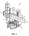
- the equipment for the change of replaceable components in machine tools which is described comprises a unified storage (40) and manipulating equipment (20) by means of which the change of replaceable components of the different categories, heads or tool holders and tools, will be carried out, both the storage (40) and the manipulating equipment (20) being independent and tight with respect to the machine tool (10), there furthermore being a loading and unloading station (30) for said components on one of the sides of said storage (40).
- Said manipulating equipment (20) with a constitution known in itself, will have a series of degrees of freedom of movements, sufficient to perform the different operations for replacing the replaceable components of the machine tool (10).
- Said machine tool (10) has, among other components, a main axis or ram (11) which moves vertically, a horizontal crossbeam (13) along which the ram (11) moves horizontally and a machining area (12) where the part to be machined is located.
- Both the storage (40) and the manipulating equipment (20) are independent and tight with respect to the machine tool (10) for assuring the precision of all the movements of the manipulating equipment (20) and that the replaceable components (80, 90) located in the storage (40) are not affected by chips being projected from the machining area (12) of the machine tool (10) which can affect the precision of the machining. Furthermore, the manipulating equipment (20) and the storage (40) are far from the machining area (12) of the machine tool (10) and are specifically located behind the horizontal movement axis (X axis) of the ram (11).
- the storage (40) can have one or more levels (43, 45) for placing the two categories (80, 90) of components to be replaced, whereas the manipulating equipment (20) will be provided with a series of degrees of freedom of movement which allow it to access the different replaceable components located in said storage (40), and transport them to the position where these components must be assembled in the ram (11) of the machine tool (10) and vice versa, or to the loading and unloading station (30) in order to locate them in the storage (40) or vice versa.
- Said change position of components in the ram (11) is a single one in the horizontal movement axis thereof (11), X axis, but not in the vertical movement axis thereof, Z axis.
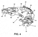
- the manipulating equipment or robot (20) has at least one manipulator (50), which is shown in a perspective view in Figure 4 , which has a first gripping device (54) for a first category.of replaceable components, such as the heads and tool holders (80) and a second gripping device (60, 70) for a second category of components.
- Said second gripping device (60, 70) is formed by two clamps (60, 70), the arms (61, 71) of which can be opened and closed by different mechanisms (62, 72), mainly a combination of a hydraulic system and springs, although other known systems such as hydraulic or pneumatic cylinders, springs, electromagnetic actuators, or a combination of the above, among others, could also be used.
- the manipulator (50) will be connected in an articulated manner to the free end of the manipulating equipment (20) as well as to the corresponding control and power supply sources, said clamps (61, 71) being intended for gripping components of the second category, i.e., tools (90).
- the first gripping device (54),located between the mentioned clamps (60 and 70) is formed in the depicted example by an intermediate conformation (54), which is sized to brace a replaceable head or tool holder (80) of a machine tool (10), i.e., suitable for the replaceable components of first category.
- This conformation (54) has anchoring and gripping means for the head or tool holder (80) which it must transport, which means can consist of, for example, fixed pins (53) and/or retractable pins (52), located in coincidence with the contour of the conformation (54) or arranged in an position adjacent to said contour.
- the manipulator (50) is equipped with proximity detectors (51, 63, 73) installed in each of the clamps (60, 70) as well as in the grip for heads or tool holders made up of the intermediate conformation (54), being intended for detecting the unexpected presence of components in the storage (40) and preventing possible collisions when the manipulator (50) moves closer to said storage (40) in order to deposit a component of any category.
- the components of the first category i.e., heads or tool holders (80).
- Said attaching flange has for its coupling, both to the intermediate conformation (54) with fixed pins (53) and/or retractable pins (52) as well as to the yokes (42) located in the storage, means complementary to those described above.
- the manipulating equipment (20) can pick up from the storage (40), in the situation of Figure 2 , a first tool holder or head (80), through the conformation (54) of the manipulator, and a first tool (90) by means of the clamps (60 or 70), moving this assembly to the ram (11) of the machine tool (10) in which it will perform, on the main axis or ram (11) thereof, firstly the placement of the first head or tool holder (80) and then the placement of the first tool (90) picked up from the storage (40).
- the manipulator (50) removes the first tool (90) from the ram (11) and then places the second tool picked up from the storage (40) last of all. It then removes the first tool (90) to the storage (40).
- the manipulator (50) removes the second tool and the first head or tool holder (80) from the ram (11), and after leaving them in the storage (40), it picks up therefrom a second head or tool holder and a new tool which it places in the ram of the machine.
- Figure 2 shows the manipulating equipment (20) in the position of access to the storage (40) for picking up a head or tool holder, if necessary, and a tool, which components it will move to the ram (11) of the machine tool (10), Figure 3 , for the replacement or change of other replaceable components.
- the manipulating equipment (20), for the movements between the storage (40), the loading and unloading station (30) and the machine tool (10) can require a rotational movement around a vertical axis or a movement along a horizontal path.
- the manipulating equipment (20) is assembled on a platform (21) independent from the machine (10), as shown in Figure 5 , and is connected to the storage (40) by means of rigid arms (22) of a fixed length.
- the storage (40) in a preferred of the invention, is made up of several levels (43), preferably with a circular arc configuration, part of which have housings (46) in which, arranged inside tool holder cups (41), the tools (90) forming one of the types of replaceable components in the machine tool (10) will be located.
- one or more of the levels of the storage (40), which have been referenced with number 45 to distinguish them, have side openings (44) which open out towards the side occupied by the manipulating equipment(20) and which are sized to frontally receive and brace the other category of replaceable components, i.e., a head or tool holder (80).
- the levels (43) with housings (46) will preferably be intended to receive and store tools (90), whereas the side openings (44) will be intended to receive heads or tool holders (90).
- yokes or jaws (42) are contemplated in the mentioned side openings (44), which yokes or jaws, as shown in Figure 6 , are made up of a considerably flat body having, from one of its edges, a notch (48) for receiving and bracing a replaceable component of the machine tool, especially a head or tool holder (80).
- Said notch (48) of the jaw or yoke (42) in turn has stops and supports (49) adapted to each replaceable component and guides (47) which will serve for positioning in a precise and repetitive manner, as well as means for gripping and retaining the component.
- the manipulating equipment (20) will have the degrees of freedom of movements necessary for carrying out all the operations in the storage (40), in the loading and unloading station (30), as well as in the machine tool (10) and the movement between them in one direction or the other.
- the loading and unloading station (30) located as has been mentioned adjacently to the storage (40), as shown in Figure 7 , is a rotary structure provided with preferably manual rotation means, which is equipped with at least one yoke or jaw (32) for locating head or tool holder (80) type components and with several tool holder cups (31), identical to those incorporated in the storage (40), for housing tool (90) type components.
- a first position in which the replaceable components are placed or removed manually
- a second position in which said components are placed or picked up by the manipulator (50) of the manipulating equipment (20) from or to the storage (40
- the equipment for the change of replaceable components in machine tools contemplates the use of a program with a code legible and/or executable by means of elements integrated in a control system which allows optimally managing the operations and movements of the manipulating equipment or robot (20) as well of the manipulator (50), for the purpose of moving, exchanging and positioning the replaceable components of different types between the ram (11) of the machine tool (10) and the storage (40) as well as between the storage (40) and the loading and unloading station (30).
Landscapes
- Engineering & Computer Science (AREA)
- Mechanical Engineering (AREA)
- Manipulator (AREA)
- Turning (AREA)
Applications Claiming Priority (1)
| Application Number | Priority Date | Filing Date | Title |
|---|---|---|---|
| PCT/ES2010/000070 WO2011101496A1 (es) | 2010-02-18 | 2010-02-18 | Equipo para intercambio de componentes sustituibles en máquinas herramientas |
Publications (3)
| Publication Number | Publication Date |
|---|---|
| EP2537629A1 EP2537629A1 (en) | 2012-12-26 |
| EP2537629A4 EP2537629A4 (en) | 2013-08-21 |
| EP2537629B1 true EP2537629B1 (en) | 2014-07-16 |
Family
ID=44482458
Family Applications (1)
| Application Number | Title | Priority Date | Filing Date |
|---|---|---|---|
| EP10846007.2A Active EP2537629B1 (en) | 2010-02-18 | 2010-02-18 | Equipment for the exchange of replaceable components in machine tools |
Country Status (6)
| Country | Link |
|---|---|
| US (1) | US20130040792A1 (zh) |
| EP (1) | EP2537629B1 (zh) |
| CN (1) | CN102811836A (zh) |
| BR (1) | BR112012020457A2 (zh) |
| ES (1) | ES2515317T3 (zh) |
| WO (1) | WO2011101496A1 (zh) |
Families Citing this family (11)
| Publication number | Priority date | Publication date | Assignee | Title |
|---|---|---|---|---|
| US20140228190A1 (en) * | 2011-09-16 | 2014-08-14 | Gmtk Multi-Process Machining, S.A. | Device for exchanging components in horizontal lathes and manipulator |
| EP2813319B1 (de) * | 2013-06-12 | 2015-08-12 | Maschinenfabrik Berthold Hermle AG | Kreisringförmiges Werkzeugmagazinregal in Turmbauweise und Verfahren zur Werkzeugumladung |
| EP2939756B1 (de) * | 2014-05-02 | 2016-07-06 | TRUMPF Werkzeugmaschinen GmbH + Co. KG | Werkzeugmaschine zum Bearbeiten eines Werkstücks mit einer Werkzeughandlingvorrichtung und einem Werkzeugmagazin sowie Verfahren und Bearbeitungsprgramm zum Betreiben einer derartigen Werkzeugmaschine |
| DE102015107257A1 (de) * | 2015-05-08 | 2016-11-10 | Grob-Werke Gmbh & Co. Kg | Bearbeitungsmaschine mit Werkzeugübergabevorrichtung |
| IT201700007989A1 (it) * | 2017-01-25 | 2018-07-25 | Fastachange S R L | Sistema di cambio utensile in presse piegatrici |
| CN108747529A (zh) * | 2018-07-19 | 2018-11-06 | 广东科杰机械自动化有限公司 | 一种阵列式刀库 |
| RU2707451C1 (ru) * | 2018-10-30 | 2019-11-26 | Акционерное общество "Научно-исследовательский технологический институт им. П.И. Снегирева" | Устройство автоматической смены инструмента |
| DE102018130317A1 (de) * | 2018-11-29 | 2020-06-04 | Atlas Copco Ias Gmbh | Magazin |
| CN110480392B (zh) * | 2019-08-26 | 2020-11-06 | 安泰天龙钨钼科技有限公司 | 一种加工中心的智能刀库系统和智能刀库系统运行方法 |
| JP7260001B2 (ja) * | 2020-01-16 | 2023-04-18 | オムロン株式会社 | プログラム生成装置、プログラム生成方法、及び生成プログラム |
| US12083665B2 (en) * | 2023-01-04 | 2024-09-10 | Shin-Yain Industrial Co., Ltd. | Tool holder module |
Family Cites Families (21)
| Publication number | Priority date | Publication date | Assignee | Title |
|---|---|---|---|---|
| US3256600A (en) * | 1963-04-23 | 1966-06-21 | Sundstrand Corp | Tool changing mechanism |
| FR2467052A1 (fr) * | 1979-10-09 | 1981-04-17 | Sculfort Machines Outils | Dispositif de poste d'outils pour machine-outil |
| SE435833B (sv) | 1980-05-13 | 1984-10-22 | Smt Machine Co Ab | Verktygsbytesanordning |
| US4404727A (en) * | 1981-02-24 | 1983-09-20 | Kearney & Trecker Corporation | Machine tool operable as both a chucking type lathe and as a machining center |
| JPS5935739B2 (ja) * | 1982-05-14 | 1984-08-30 | 株式会社オ−エム製作所 | 工作機械の工具交換装置 |
| DE3316999A1 (de) * | 1982-08-05 | 1984-02-09 | VEB Werkzeugmaschinenkombinat "Fritz Heckert" Karl-Marx-Stadt, DDR 9030 Karl-Marx-Stadt | Vorrichtung zur speicherung von werkzeugen einer automatischen werkzeugmaschine |
| DE3320762C2 (de) * | 1983-06-09 | 1994-10-27 | Trumpf Gmbh & Co | Stanzmaschine mit einem stationären Magazin |
| SU1135593A1 (ru) * | 1983-10-03 | 1985-01-23 | Ульяновское Головное Специальное Конструкторское Бюро Тяжелых И Фрезерных Станков | Устройство дл автоматической смены инструмента |
| NL8501136A (nl) | 1985-04-18 | 1986-11-17 | Visser Norbert | Mondstuk voor een blaasinstrument met enkel riet. |
| US4858980A (en) * | 1988-08-23 | 1989-08-22 | Cincinnati Milacron Inc. | Article gripper |
| DE19515041C1 (de) * | 1995-04-24 | 1996-08-29 | Traub Ag | Einrichtung zum Wechseln von Gegenständen zwischen einer Werkzeugmaschine und einem Magazin |
| JP3547903B2 (ja) * | 1996-03-26 | 2004-07-28 | オークマ株式会社 | 盲蓋着脱方法 |
| DE29821047U1 (de) * | 1998-11-25 | 1999-04-01 | Laempe, Hans Joachim, Dipl.-Ing., 79692 Raich | Werkzeugmaschinen-Anordnung mit einer Vorrichtung für einen automatischen Werkzeugwechsel |
| DE19854276C2 (de) * | 1998-11-25 | 2002-09-26 | Hans Joachim Laempe | Werkzeugmaschinen-Anordnung mit einer Vorrichtung für einen automatischen Werkzeugwechsel |
| DE19860492B4 (de) * | 1998-12-28 | 2005-09-15 | Deckel Maho Gmbh | Programmgesteuerte Fräs- und Bohrmaschine |
| DE10236342B4 (de) * | 2002-08-08 | 2018-02-22 | Gebr. Heller Maschinenfabrik Gmbh | Verfahren zum Bestücken von Werkzeugen in Werkzeugmagazinen sowie Vorrichtung zur Durchführung eines solchen Verfahrens |
| EP1894649A1 (de) * | 2006-09-01 | 2008-03-05 | Stopinc Aktiengesellschaft | Anlage zur Wartung eines am Ausguss eines Behälters für Metallschmelze montierten Schiebeverschlusses |
| DE102007018368B4 (de) * | 2007-04-18 | 2017-11-02 | Isog Technology Gmbh & Co. Kg | Werkzeugmaschinenanordnung mit automatischem Werkstück- und Werkzeugwechsel |
| CN201224043Y (zh) * | 2008-07-03 | 2009-04-22 | 大连首轮机械工业有限公司 | 曲线板、扭簧、曲线轴承、刀爪锁定作同步位移换刀机构 |
| CN201244736Y (zh) * | 2008-07-09 | 2009-05-27 | 新颖机械工业股份有限公司 | 机械加工母机自动换头夹持机构 |
| CN201295852Y (zh) * | 2008-11-13 | 2009-08-26 | 东风汽车有限公司设备制造厂 | 机床主轴自动换刀装置 |
-
2010
- 2010-02-18 CN CN2010800643222A patent/CN102811836A/zh active Pending
- 2010-02-18 WO PCT/ES2010/000070 patent/WO2011101496A1/es active Application Filing
- 2010-02-18 US US13/579,736 patent/US20130040792A1/en not_active Abandoned
- 2010-02-18 ES ES10846007.2T patent/ES2515317T3/es active Active
- 2010-02-18 EP EP10846007.2A patent/EP2537629B1/en active Active
- 2010-02-18 BR BR112012020457A patent/BR112012020457A2/pt not_active IP Right Cessation
Also Published As
| Publication number | Publication date |
|---|---|
| WO2011101496A1 (es) | 2011-08-25 |
| US20130040792A1 (en) | 2013-02-14 |
| EP2537629A4 (en) | 2013-08-21 |
| BR112012020457A2 (pt) | 2017-06-13 |
| CN102811836A (zh) | 2012-12-05 |
| ES2515317T3 (es) | 2014-10-29 |
| EP2537629A1 (en) | 2012-12-26 |
Similar Documents
| Publication | Publication Date | Title |
|---|---|---|
| EP2537629B1 (en) | Equipment for the exchange of replaceable components in machine tools | |
| US20070184954A1 (en) | Method and system for loading and unloading a machine tool with tools | |
| KR101271564B1 (ko) | 머시닝센터의 자동 공구교환장치 | |
| JPS6176250A (ja) | ロボツトによる交換システム | |
| JPS5949859B2 (ja) | 工作機械のための工具の保管、交換方法ならびにその装置 | |
| US11712770B2 (en) | Machine tool | |
| JPH01127243A (ja) | 工作機械の為の工具ラック | |
| US9481062B2 (en) | Method and apparatus for changing tools | |
| US20060075625A1 (en) | Multiple side processing machine and positioning device for a workpiece | |
| KR101225189B1 (ko) | 머시닝센터의 자동공구교환장치 | |
| WO2023217794A1 (en) | Machine tool and method of operating the machine tool | |
| JP6576662B2 (ja) | 工作機械におけるツールマガジン装置 | |
| US7048679B2 (en) | Tool-changing system | |
| JP7285330B2 (ja) | 工作機械 | |
| TW201800174A (zh) | 機床機座、機床工作模組、機床以及由上述機床組成之生產線 | |
| US20140106950A1 (en) | Method for Changing a Gear Cutting Tool with Double-Sided Bearing in a Gear Cutting Machine and Device Therefor | |
| EP2371481B1 (en) | Machining centre with tool-changing arm | |
| JPS5949144B2 (ja) | 自動工具交換装置 | |
| US20230173627A1 (en) | Tool changing device, machine tool and method for changing a tool | |
| JPS6040341B2 (ja) | 工具の取替え方法 | |
| JP7378541B1 (ja) | 加工システム | |
| JP4278467B2 (ja) | 工作機械 | |
| EP4306260A1 (en) | Conveyance system | |
| US20240253172A1 (en) | Combined transfer and storage device and manufacturing line for machining | |
| US20210154787A1 (en) | Processing machine line |
Legal Events
| Date | Code | Title | Description |
|---|---|---|---|
| PUAI | Public reference made under article 153(3) epc to a published international application that has entered the european phase |
Free format text: ORIGINAL CODE: 0009012 |
|
| 17P | Request for examination filed |
Effective date: 20120817 |
|
| AK | Designated contracting states |
Kind code of ref document: A1 Designated state(s): AT BE BG CH CY CZ DE DK EE ES FI FR GB GR HR HU IE IS IT LI LT LU LV MC MK MT NL NO PL PT RO SE SI SK SM TR |
|
| DAX | Request for extension of the european patent (deleted) | ||
| A4 | Supplementary search report drawn up and despatched |
Effective date: 20130718 |
|
| RIC1 | Information provided on ipc code assigned before grant |
Ipc: B23Q 3/155 20060101AFI20130712BHEP Ipc: B23Q 3/157 20060101ALI20130712BHEP |
|
| GRAP | Despatch of communication of intention to grant a patent |
Free format text: ORIGINAL CODE: EPIDOSNIGR1 |
|
| RIC1 | Information provided on ipc code assigned before grant |
Ipc: B23Q 3/155 20060101AFI20140127BHEP Ipc: B23Q 3/157 20060101ALI20140127BHEP |
|
| INTG | Intention to grant announced |
Effective date: 20140226 |
|
| GRAS | Grant fee paid |
Free format text: ORIGINAL CODE: EPIDOSNIGR3 |
|
| GRAA | (expected) grant |
Free format text: ORIGINAL CODE: 0009210 |
|
| AK | Designated contracting states |
Kind code of ref document: B1 Designated state(s): AT BE BG CH CY CZ DE DK EE ES FI FR GB GR HR HU IE IS IT LI LT LU LV MC MK MT NL NO PL PT RO SE SI SK SM TR |
|
| REG | Reference to a national code |
Ref country code: GB Ref legal event code: FG4D |
|
| REG | Reference to a national code |
Ref country code: CH Ref legal event code: EP |
|
| REG | Reference to a national code |
Ref country code: IE Ref legal event code: FG4D |
|
| REG | Reference to a national code |
Ref country code: AT Ref legal event code: REF Ref document number: 677295 Country of ref document: AT Kind code of ref document: T Effective date: 20140815 |
|
| REG | Reference to a national code |
Ref country code: DE Ref legal event code: R096 Ref document number: 602010017623 Country of ref document: DE Effective date: 20140828 |
|
| REG | Reference to a national code |
Ref country code: ES Ref legal event code: FG2A Ref document number: 2515317 Country of ref document: ES Kind code of ref document: T3 Effective date: 20141029 |
|
| REG | Reference to a national code |
Ref country code: NL Ref legal event code: VDEP Effective date: 20140716 |
|
| REG | Reference to a national code |
Ref country code: AT Ref legal event code: MK05 Ref document number: 677295 Country of ref document: AT Kind code of ref document: T Effective date: 20140716 |
|
| REG | Reference to a national code |
Ref country code: LT Ref legal event code: MG4D |
|
| PG25 | Lapsed in a contracting state [announced via postgrant information from national office to epo] |
Ref country code: BG Free format text: LAPSE BECAUSE OF FAILURE TO SUBMIT A TRANSLATION OF THE DESCRIPTION OR TO PAY THE FEE WITHIN THE PRESCRIBED TIME-LIMIT Effective date: 20141016 Ref country code: FI Free format text: LAPSE BECAUSE OF FAILURE TO SUBMIT A TRANSLATION OF THE DESCRIPTION OR TO PAY THE FEE WITHIN THE PRESCRIBED TIME-LIMIT Effective date: 20140716 Ref country code: SE Free format text: LAPSE BECAUSE OF FAILURE TO SUBMIT A TRANSLATION OF THE DESCRIPTION OR TO PAY THE FEE WITHIN THE PRESCRIBED TIME-LIMIT Effective date: 20140716 Ref country code: NO Free format text: LAPSE BECAUSE OF FAILURE TO SUBMIT A TRANSLATION OF THE DESCRIPTION OR TO PAY THE FEE WITHIN THE PRESCRIBED TIME-LIMIT Effective date: 20141016 Ref country code: PT Free format text: LAPSE BECAUSE OF FAILURE TO SUBMIT A TRANSLATION OF THE DESCRIPTION OR TO PAY THE FEE WITHIN THE PRESCRIBED TIME-LIMIT Effective date: 20141117 Ref country code: LT Free format text: LAPSE BECAUSE OF FAILURE TO SUBMIT A TRANSLATION OF THE DESCRIPTION OR TO PAY THE FEE WITHIN THE PRESCRIBED TIME-LIMIT Effective date: 20140716 |
|
| PG25 | Lapsed in a contracting state [announced via postgrant information from national office to epo] |
Ref country code: AT Free format text: LAPSE BECAUSE OF FAILURE TO SUBMIT A TRANSLATION OF THE DESCRIPTION OR TO PAY THE FEE WITHIN THE PRESCRIBED TIME-LIMIT Effective date: 20140716 Ref country code: NL Free format text: LAPSE BECAUSE OF FAILURE TO SUBMIT A TRANSLATION OF THE DESCRIPTION OR TO PAY THE FEE WITHIN THE PRESCRIBED TIME-LIMIT Effective date: 20140716 Ref country code: IS Free format text: LAPSE BECAUSE OF FAILURE TO SUBMIT A TRANSLATION OF THE DESCRIPTION OR TO PAY THE FEE WITHIN THE PRESCRIBED TIME-LIMIT Effective date: 20141116 Ref country code: PL Free format text: LAPSE BECAUSE OF FAILURE TO SUBMIT A TRANSLATION OF THE DESCRIPTION OR TO PAY THE FEE WITHIN THE PRESCRIBED TIME-LIMIT Effective date: 20140716 Ref country code: CY Free format text: LAPSE BECAUSE OF FAILURE TO SUBMIT A TRANSLATION OF THE DESCRIPTION OR TO PAY THE FEE WITHIN THE PRESCRIBED TIME-LIMIT Effective date: 20140716 Ref country code: LV Free format text: LAPSE BECAUSE OF FAILURE TO SUBMIT A TRANSLATION OF THE DESCRIPTION OR TO PAY THE FEE WITHIN THE PRESCRIBED TIME-LIMIT Effective date: 20140716 |
|
| REG | Reference to a national code |
Ref country code: DE Ref legal event code: R097 Ref document number: 602010017623 Country of ref document: DE |
|
| PG25 | Lapsed in a contracting state [announced via postgrant information from national office to epo] |
Ref country code: RO Free format text: LAPSE BECAUSE OF FAILURE TO SUBMIT A TRANSLATION OF THE DESCRIPTION OR TO PAY THE FEE WITHIN THE PRESCRIBED TIME-LIMIT Effective date: 20140716 Ref country code: CZ Free format text: LAPSE BECAUSE OF FAILURE TO SUBMIT A TRANSLATION OF THE DESCRIPTION OR TO PAY THE FEE WITHIN THE PRESCRIBED TIME-LIMIT Effective date: 20140716 Ref country code: SK Free format text: LAPSE BECAUSE OF FAILURE TO SUBMIT A TRANSLATION OF THE DESCRIPTION OR TO PAY THE FEE WITHIN THE PRESCRIBED TIME-LIMIT Effective date: 20140716 Ref country code: DK Free format text: LAPSE BECAUSE OF FAILURE TO SUBMIT A TRANSLATION OF THE DESCRIPTION OR TO PAY THE FEE WITHIN THE PRESCRIBED TIME-LIMIT Effective date: 20140716 Ref country code: EE Free format text: LAPSE BECAUSE OF FAILURE TO SUBMIT A TRANSLATION OF THE DESCRIPTION OR TO PAY THE FEE WITHIN THE PRESCRIBED TIME-LIMIT Effective date: 20140716 |
|
| PLBE | No opposition filed within time limit |
Free format text: ORIGINAL CODE: 0009261 |
|
| STAA | Information on the status of an ep patent application or granted ep patent |
Free format text: STATUS: NO OPPOSITION FILED WITHIN TIME LIMIT |
|
| 26N | No opposition filed |
Effective date: 20150417 |
|
| PG25 | Lapsed in a contracting state [announced via postgrant information from national office to epo] |
Ref country code: BE Free format text: LAPSE BECAUSE OF NON-PAYMENT OF DUE FEES Effective date: 20150228 |
|
| PG25 | Lapsed in a contracting state [announced via postgrant information from national office to epo] |
Ref country code: LU Free format text: LAPSE BECAUSE OF FAILURE TO SUBMIT A TRANSLATION OF THE DESCRIPTION OR TO PAY THE FEE WITHIN THE PRESCRIBED TIME-LIMIT Effective date: 20150218 |
|
| REG | Reference to a national code |
Ref country code: CH Ref legal event code: PL |
|
| GBPC | Gb: european patent ceased through non-payment of renewal fee |
Effective date: 20150218 |
|
| PG25 | Lapsed in a contracting state [announced via postgrant information from national office to epo] |
Ref country code: CH Free format text: LAPSE BECAUSE OF NON-PAYMENT OF DUE FEES Effective date: 20150228 Ref country code: MC Free format text: LAPSE BECAUSE OF FAILURE TO SUBMIT A TRANSLATION OF THE DESCRIPTION OR TO PAY THE FEE WITHIN THE PRESCRIBED TIME-LIMIT Effective date: 20140716 Ref country code: LI Free format text: LAPSE BECAUSE OF NON-PAYMENT OF DUE FEES Effective date: 20150228 |
|
| REG | Reference to a national code |
Ref country code: IE Ref legal event code: MM4A |
|
| PG25 | Lapsed in a contracting state [announced via postgrant information from national office to epo] |
Ref country code: SI Free format text: LAPSE BECAUSE OF FAILURE TO SUBMIT A TRANSLATION OF THE DESCRIPTION OR TO PAY THE FEE WITHIN THE PRESCRIBED TIME-LIMIT Effective date: 20140716 |
|
| PG25 | Lapsed in a contracting state [announced via postgrant information from national office to epo] |
Ref country code: IE Free format text: LAPSE BECAUSE OF NON-PAYMENT OF DUE FEES Effective date: 20150218 Ref country code: GB Free format text: LAPSE BECAUSE OF NON-PAYMENT OF DUE FEES Effective date: 20150218 |
|
| REG | Reference to a national code |
Ref country code: FR Ref legal event code: PLFP Year of fee payment: 7 |
|
| PG25 | Lapsed in a contracting state [announced via postgrant information from national office to epo] |
Ref country code: BE Free format text: LAPSE BECAUSE OF FAILURE TO SUBMIT A TRANSLATION OF THE DESCRIPTION OR TO PAY THE FEE WITHIN THE PRESCRIBED TIME-LIMIT Effective date: 20140716 |
|
| PG25 | Lapsed in a contracting state [announced via postgrant information from national office to epo] |
Ref country code: MT Free format text: LAPSE BECAUSE OF FAILURE TO SUBMIT A TRANSLATION OF THE DESCRIPTION OR TO PAY THE FEE WITHIN THE PRESCRIBED TIME-LIMIT Effective date: 20140716 |
|
| REG | Reference to a national code |
Ref country code: FR Ref legal event code: PLFP Year of fee payment: 8 |
|
| PG25 | Lapsed in a contracting state [announced via postgrant information from national office to epo] |
Ref country code: HU Free format text: LAPSE BECAUSE OF FAILURE TO SUBMIT A TRANSLATION OF THE DESCRIPTION OR TO PAY THE FEE WITHIN THE PRESCRIBED TIME-LIMIT; INVALID AB INITIO Effective date: 20100218 Ref country code: SM Free format text: LAPSE BECAUSE OF FAILURE TO SUBMIT A TRANSLATION OF THE DESCRIPTION OR TO PAY THE FEE WITHIN THE PRESCRIBED TIME-LIMIT Effective date: 20140716 |
|
| PG25 | Lapsed in a contracting state [announced via postgrant information from national office to epo] |
Ref country code: GR Free format text: LAPSE BECAUSE OF FAILURE TO SUBMIT A TRANSLATION OF THE DESCRIPTION OR TO PAY THE FEE WITHIN THE PRESCRIBED TIME-LIMIT Effective date: 20140716 |
|
| PG25 | Lapsed in a contracting state [announced via postgrant information from national office to epo] |
Ref country code: HR Free format text: LAPSE BECAUSE OF FAILURE TO SUBMIT A TRANSLATION OF THE DESCRIPTION OR TO PAY THE FEE WITHIN THE PRESCRIBED TIME-LIMIT Effective date: 20140716 |
|
| PG25 | Lapsed in a contracting state [announced via postgrant information from national office to epo] |
Ref country code: TR Free format text: LAPSE BECAUSE OF FAILURE TO SUBMIT A TRANSLATION OF THE DESCRIPTION OR TO PAY THE FEE WITHIN THE PRESCRIBED TIME-LIMIT Effective date: 20140716 |
|
| REG | Reference to a national code |
Ref country code: FR Ref legal event code: PLFP Year of fee payment: 9 |
|
| PG25 | Lapsed in a contracting state [announced via postgrant information from national office to epo] |
Ref country code: MK Free format text: LAPSE BECAUSE OF FAILURE TO SUBMIT A TRANSLATION OF THE DESCRIPTION OR TO PAY THE FEE WITHIN THE PRESCRIBED TIME-LIMIT Effective date: 20140716 |
|
| PGFP | Annual fee paid to national office [announced via postgrant information from national office to epo] |
Ref country code: ES Payment date: 20240307 Year of fee payment: 15 |
|
| PGFP | Annual fee paid to national office [announced via postgrant information from national office to epo] |
Ref country code: DE Payment date: 20240228 Year of fee payment: 15 |
|
| PGFP | Annual fee paid to national office [announced via postgrant information from national office to epo] |
Ref country code: IT Payment date: 20240222 Year of fee payment: 15 Ref country code: FR Payment date: 20240226 Year of fee payment: 15 |
|
| REG | Reference to a national code |
Ref country code: DE Ref legal event code: R081 Ref document number: 602010017623 Country of ref document: DE Owner name: VERTICAL MULTITASKING TECHNOLOGY S.L., ES Free format text: FORMER OWNER: GMTK MULTI-PROCESS MACHINING S.A., ZESTOA, ES |