EP2535875B1 - Procédé et dispositif destinés à l'identification de boules de jeu - Google Patents
Procédé et dispositif destinés à l'identification de boules de jeu Download PDFInfo
- Publication number
- EP2535875B1 EP2535875B1 EP11450010.1A EP11450010A EP2535875B1 EP 2535875 B1 EP2535875 B1 EP 2535875B1 EP 11450010 A EP11450010 A EP 11450010A EP 2535875 B1 EP2535875 B1 EP 2535875B1
- Authority
- EP
- European Patent Office
- Prior art keywords
- image
- gaming ball
- ball
- unit
- recording unit
- Prior art date
- Legal status (The legal status is an assumption and is not a legal conclusion. Google has not performed a legal analysis and makes no representation as to the accuracy of the status listed.)
- Active
Links
Images


Classifications
-
- G—PHYSICS
- G06—COMPUTING; CALCULATING OR COUNTING
- G06V—IMAGE OR VIDEO RECOGNITION OR UNDERSTANDING
- G06V20/00—Scenes; Scene-specific elements
- G06V20/60—Type of objects
- G06V20/66—Trinkets, e.g. shirt buttons or jewellery items
-
- G—PHYSICS
- G06—COMPUTING; CALCULATING OR COUNTING
- G06V—IMAGE OR VIDEO RECOGNITION OR UNDERSTANDING
- G06V20/00—Scenes; Scene-specific elements
- G06V20/60—Type of objects
- G06V20/62—Text, e.g. of license plates, overlay texts or captions on TV images
- G06V20/63—Scene text, e.g. street names
-
- G—PHYSICS
- G07—CHECKING-DEVICES
- G07C—TIME OR ATTENDANCE REGISTERS; REGISTERING OR INDICATING THE WORKING OF MACHINES; GENERATING RANDOM NUMBERS; VOTING OR LOTTERY APPARATUS; ARRANGEMENTS, SYSTEMS OR APPARATUS FOR CHECKING NOT PROVIDED FOR ELSEWHERE
- G07C15/00—Generating random numbers; Lottery apparatus
- G07C15/001—Generating random numbers; Lottery apparatus with balls or the like
-
- G—PHYSICS
- G06—COMPUTING; CALCULATING OR COUNTING
- G06F—ELECTRIC DIGITAL DATA PROCESSING
- G06F2218/00—Aspects of pattern recognition specially adapted for signal processing
- G06F2218/12—Classification; Matching
-
- G—PHYSICS
- G06—COMPUTING; CALCULATING OR COUNTING
- G06V—IMAGE OR VIDEO RECOGNITION OR UNDERSTANDING
- G06V2201/00—Indexing scheme relating to image or video recognition or understanding
- G06V2201/02—Recognising information on displays, dials, clocks
Definitions
- the invention relates to a method according to the preamble of patent claim 1. Furthermore, the invention relates to a device according to the preamble of patent claim 12.
- Methods and devices according to the invention are preferably used in the field of automated gaming.
- such methods and apparatus may be used to perform an automated bingo game.
- Background of the invention is the automated detection of game balls after their selection or draw from a predetermined number of balls game.
- Typical games with game balls to draw such. Lotto, Bingo, etc. need to play a slot machine through which an objective creation of random numbers is guaranteed.
- the randomness of the game result should be obvious, in particular, the player should be given the feeling that the drawing is carried out without manipulation to his detriment.
- game machines are used in the prior art, which also make an automated identification of the game balls in addition to the automated drawing of balls.
- the Belelkugein are provided with transponder chips and the identification is carried out via RFID.
- Other systems use barcodes to identify the game balls.
- Still other systems use cameras and special algorithms to identify the symbols imprinted or imprinted on the balls.
- the invention thus has the object to improve the identification or identification of the balls and to provide a method and a device, with which the detection of the balls is improved and less error prone.
- the invention solves this problem in a device of the type mentioned above with the features of the characterizing part of claim 12.
- the recognition or identification of the selected ball game can be performed much more reliable and can be avoided due to a mispositioning of the selected ball caused false detections.
- the game ball can be repositioned and evaluated.
- the game ball in order to determine the center of mass of the image of the selected game ball in the image of the image recording unit, the game ball is stopped and remains stationary relative to the image recording unit.
- Another particular aspect of the invention provides that the game ball is moved by means of a ball guide unit from the starting position along a predetermined path through the receiving area of the image pickup unit, the respective selected ball is removed after their movement over the predetermined path from the ball guide unit and optionally forwarded ,
- the selected ball is moved on the predetermined path circular arc on a horizontal plane, wherein the recording direction or the visual beam of the image pickup unit is substantially horizontal and is preferably directed to a point on the predetermined path in which the Game ball of the image acquisition unit is the closest.
- the game ball is received by a circular recess of the substantially flat and disk-shaped ball guide unit and secured against lateral rolling.
- the game ball is thrown or dropped from above into or on the circular recess and wherein preferably the case of the game ball, in particular by a below the recess located elastic damping unit, is braked.
- a particular aspect of the invention provides that the game ball is guided and / or rotated in the recess of the ball guide unit and is supported on a base plate located below the disc-shaped ball guide unit. This allows for a mechanically simple construction and causes the game ball to rotate during its course along the given path and thus increase the probability of error-free detection of the symbols, since the game ball is visible from different directions.
- the game ball falls at the end of the path through a recess located in the base plate and is transported further. This allows easy removal of the Sptelkugel after identification.
- the image acquisition unit continuously creates images at predetermined time intervals. This allows a multiplicity of different mutually independent identification processes and increases the accuracy of detection and / or the accuracy of the detection.
- these images are preferably displayed visibly on a monitor for the players This gives the player a better overview of the game and the player the impression of a tamper-free and fair game suggests.
- a development of the invention provides that a number of, in particular four, images is created during the predetermined period and the identification of the ball based on at least two at different times taken pictures, wherein the identification for each of the images is made separately and wherein each identification of an image provides a separate identification result, wherein an identification is considered to be correct only if a predetermined number, in particular of at least half, preferably all, of the identification results is identical.
- the reliability of the identification can be further increased.
- the recognition or identitication of the selected ball is much more reliable. False detections, which are caused by a mispositioning of the selected ball game can be effectively and reliably avoided.
- the game ball can be repositioned and evaluated.
- a control unit may be provided which stops or sets inactive the means for moving the game ball to fix the center of mass of the image of the selected ball in the image of the image pickup unit, so that the ball remains immobile relative to the image pickup.
- a ball guide unit is provided with the game ball from the starting position along a predetermined path through the receiving area of the image pickup unit is movable, wherein the respective selected game ball after their movement over the predetermined path the ball guide unit falls.
- a mechanically particularly advantageous embodiment of the invention provides that the ball guide unit as a flat, in particular transparent, thin plate. in particular as a circular disk, is formed, which for receiving the game ball at least one eccentrically arranged, in particular circular.
- the Platta the Kugel Resultssefnheit is arranged horizontally and about a pivot point, in particular the center of the circular disc, rotatably and / or pivotally mounted, and wherein the receiving direction or the visual beam of the image pickup unit is substantially horizontal and preferably to a point on the directed way in which the game ball of the image pickup unit is closest.
- an inlet is provided which lies directly above a point on the predetermined path, wherein in particular immediately below the inlet, an elastic damping unit is provided for braking a game ball. This prevents destruction of the balls and prolongs the life of the slot machine as the game balls.
- a particular aspect of the invention provides that a base plate for supporting and guiding the game balls is provided underneath the disk-shaped ball guide unit. This allows a mechanically simple construction and causes the game ball to rotate during its course along the predetermined path and thus the probability of error-free detection The symbols rise because the ball is visible from different directions.
- a recess of the size of a game ball is provided, so that a game ball can fall through this recess. This allows easy removal of the ball after identification.
- a monitor may be provided which continuously displays images taken at predetermined time intervals by the image acquisition unit. This allows a variety of different mutually independent identification processes and increases the detection Surelgkelt or security. It gives the player a better overview of the game and suggests to the player the impression of a tamper-free and fair game.
- the recess is continued to the edge of the ball guide unit and a hemisphere of the ball is shown in at least one position of the path completely from the image pickup unit and in particular of the ball guide unit not is covered.
- Fig. 1 shows a ball drawing machine 1.
- Fig. 2 schematically shows an advantageous embodiment of a device according to the invention for the identification of the balls 2 in detail.
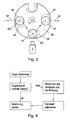
- the structure and operation of the carousel is In Fig. 3 shown schematically.
- the method for adjusting the carousel 74 is in Fig. 4 shown.
- a typical game ball is in the Fig. 5a, 5b shown in color or black and white.
- Fig. 6 shows the determination of the position of the ball in the picture.
- Fig. 7 shows an incorrectly positioned game ball.
- Fig. 8 shows a correctly positioned game ball.
- Fig. 9 shows the circle determined by the detection of the ball.
- Fig. 10 shows the area of the image created by the image acquisition unit, which is characterized by the center-point coordinates and the radius.
- Fig. 11 shows the position of the detected circles on the respective balls.
- Fig. 13 shows the masks for the detected circles,
- Fig. 14 shows the image areas in the masks or in the circles.
- Fig. 15 shows the alignment of the symbols in the respective image areas.
- Fig. 16 shows the normalized. ie rotated and scaled image areas with the symbols,
- Fig. 16a shows the In Fig. 16 displayed image areas after a threshold operation.
- Fig. 17 shows the display content of a terminal for a player during the staging phase.
- Fig. 18 shows the display content terminal during the draw.
- Fig. 19 shows the Displaylnhalt terminal in case of a game win.
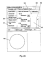
- Fig. 20 shows the user interface for the game operator.
- Fig. 1 shows a ball drawing machine 1 for drawing balls 2 for a bingo game
- a machine assembly 1 with a base 34 and a built-up on the base 34 Kugelziahungsautomaten 1.
- a spherical glass envelope is arranged as a cover 350, which prevents the immediate access of a player to the ball drawing machine 1.
- the glass envelope is transparent in the present case. This has the particular advantage that the ball drawing machine 1 and the machine assembly can be centrally placed or arranged in rooms and that individual players around the machine assembly 1 can take up.
- glass envelope 350 may also be at least partially opaque or opaque, wherein advantageously the view of the essential parts of the gaming machine is free.
- This cover 350 is spherically formed in the present case, however, because of its essential purpose to protect the ball drawing machine 1 from the access of players, but any other shape, such as a cylindrical shape or a conical shape can be selected as long as the access of individual players on the ball drawing machine 1 is prevented.
- Fig. 2 shows schematically an advantageous embodiment of a device according to the invention for the identification of the game balls 2.
- the ball guide 72 includes a body with a number of arranged rods 721, within which the game ball 2 is guided. By the rods 721 a path 42 is given along which a falling through the downpipe 71 game ball 2 moves on.
- the game ball 2 arrives at the end of the ball guide 72 in an inlet 73 in the form of a throw basket 73.
- the game ball 2 is braked in the throw basket 73 in its horizontal movement and falls through the throw basket 73 vertically downwards in the area of a carousel 74th
- the structure and operation of the carousel 74 is in Fig. 3
- the carousel 74 comprises a ball guide unit 4 in the form of a thin circular, in Fig. 3
- the plate 40 is mounted rotatably or pivotably about an axis normal to the plate plane and through the center of the circle of the plate 40 extending axis.
- the rotation is in the present example viewed from above counterclockwise.
- the plate 40 and the ball guide unit 4 has four circumferentially arranged circular recesses 44 which are slightly larger than the diameter of the respective play ball 2. During the rotation, the recesses 44 move in the circumferential direction of the circular plate 40 and are in an offset position shown in phantom with the reference numeral 44 '.
- a base plate 45 Immediately below the rotatable or pivotally mounted plate 40 of the ball guide unit 4 is a base plate 45.
- an elastic damping unit 47 which brakes the falling through the throw basket 73 game ball 2 and ensures that the respective game ball 2 is not damaged.
- the elastic damping unit 47 is embodied by a rubber band or a rubber buffer, which is arranged directly below the drop basket 73 on the base plate 45. The rubber band is arranged such that no Tell the game ball 2 at Immediately striking the base plate 45 touched.
- the plate 40 is rotated and the ball located in the recess 44 2 along a predetermined circular path 42 rotates and / or moves.
- the carousel 74 has a side panel 741, which has a recess 742.
- the image pickup unit 3 is horizontally directed to the recess 742.
- game balls 2 located inside the carousel 74 may be picked up by the image pickup unit 3 located outside the carousel 74. If the plate 40 of the carousel 74 rotates in the counterclockwise direction, then the selected game ball 2 passes on its predetermined path 42 through the carousel 74 through the receiving area of the image recording unit 3 and is detected by the latter.
- the carousel 74 is driven by a motor 75, in the present case with a stepper motor 75, which is located below the base plate 45 and which is connected to the base plate 45.
- the recesses 44 continue to the edge of the plate 40 or the ball guide unit 4, as in FIG Fig. 3 shown in the alternative recess.
- Such an alternative recess has the considerable advantage that the game ball 2 is not covered or covered during its recording by the image recording unit 3.
- the game ball 2 is guided by the side panel 741 of the carousel 74 or by the transparent cover located in the region of the recess 742 of the panel 741, so that the position of the ball 2 is fixed on the path 42.
- the edge of the recess of the plate 40 of the Kugei arrangementselnheit 4 and the carousel 74 does not even partially cover the selected ball game 2, so that an improved evaluation is possible.
- the illustration of different recesses 44 is used to illustrate possible different types of guidance of the playing ball 2 in the carousel 74.
- the plate of the carousel 74 always includes recesses 44 of the same shape.
- the Base plate 45 has a recess 46 through which the game ball 2 can fall down. In this embodiment, this recess 46 is circular.
- this recess 46 includes another ball guide 76, which passes the game ball 2 to a lifting device 77.
- the lifting device 77 leads the game ball 2, via a further ball guide, not shown, 2 again to the draw.
- the drawn game balls 2 can be stored until completion of each game and returned to the draw after completing the game to prevent the multiple draw a ball game 2 during the same game.
- a typical game ball 2 is in Fig. 5a, 5b shown.
- the game ball 2 carries on its surface a symbol 21 printed several times, which is located within a circle 22.
- a marking line 23 In the direction of writing below the symbol 21 there is a marking line 23, which by means of an auxiliary line 24, which protrudes in the direction of writing down and connected to the circle 22.
- the image pickup unit 3 continuously creates images of the game ball 2.
- the game ball 2 is stopped on its way in a position 421 in the recording area of the image pickup unit 3.
- the image recording unit 3 is pivotally mounted by a further motor and the game ball 2 is tracked, wherein the center of mass M of the image of the game ball 2 is kept constant in the image.
- the further motor (not shown in the figure) is preceded by a control unit, which is connected downstream of the image recording unit 3 and controls the further motor in such a way that the image of the game ball is located completely in the recording area of the image recording unit 3.
- the images taken by the image recording unit 3 are additionally displayed on a monitor, not shown, facing the players.
- a recording of a game ball 2 is schematically in Fig. 5a, 5b shown.
- the image 300 created by the image pickup unit 3 is in Fig. 6 Furthermore, an image 31 of the respective symbol 21, an image 32 of the marking line 23 and an image 33 of the respective auxiliary line 24 as well as an image 30 of the circle 22 are shown.
- the image position of the image 35 of the ball 2 in the image 300 created by the image-capturing unit 3 is shown in FIG Fig. 6 , determined.
- the diameter d of the image 35 of the ball 2 and the lateral distance b of the image 35 of the ball 2 from the left edge of the image - in each case in pixels - are determined.
- the deviation of position D from the optimal left margin can be determined, comparing the difference with a threshold T. If the difference exceeds the threshold value, in particular the image 35 of the game ball 2 is located, as in FIG Fig. 7 shown, partially outside the picture, the game ball 2 is repositioned.
- the game ball 2 for this purpose on the way 42 in a starting position 422 ( Fig. 3 ) and the entire movement of the ball 2 by the receiving area of the image processing unit 3 are repeated.
- a precise positionable motor 75 of stepper motors the incorrectly positioned game ball 2 according to the invention on the basis of the calculated position D along or against the direction of travel and to repeat the determination of the position of the game ball D so long until the game ball 2 is wholly in the picking area of the image processing unit 3 and the image 35 of the game ball 2 is completely contained in the image formed by the image pickup unit 3.
- the method for adjusting the carousel 74 is in Fig. 4 shown.
- an identification process is started which determines the symbol 21 displayed on the game ball 2 based on the image taken by the image pickup unit 3.
- the image capture unit 3 creates color images ( Fig. 5a ), which, however, before being further processed in greyscale images ( Fig. 5b ) are converted.
- the image position and the size of the circle are determined by means of a detection method and stored in the form of the center point coordinates xb, yb and the diameter or the radius rb. It will be the in Fig. 9 created circle with the determined coordinates and the radius determined for further processing.
- Fig. 10 shows the area 301 of the image 300 created by the image pickup unit 3, which is represented by the center coordinates xb. yb and the radius rb is characterized.
- the distortion caused by the spherical surface of the balls 2 is corrected by an equalization.
- Methods for equalizing symbols printed on a spherical surface are well known to those skilled in the art.
- a calibration may take place by means of which circular areas located on the game ball 2 are simply imaged onto circular areas of the rectified image.
- the result of the equalization is in Fig. 11 represented, with only very small residual errors or residual distortions remain.
- the equalization operation further comprises scaling the image. so that the rectified image is the same size as the original image.
- Fig. 13 shows the image areas or masks 39 located in the detected circles, wherein Fig. 13 the respective masks 39 are shown.
- Fig. 14 shows the image areas of the rectified image masked by the masks 39.
- a marker point 38 is determined which results as the intersection of the respective images 31, 32 of the marker line 23 and the auxiliary line 24 of the respective match ball 2.
- Fig. 15 shows the two detected masks 39, wherein on each of the masks 39 a connecting line 37 between the respective center of the mask 39 and the respective marking point 38 is shown.
- the connecting line 37 is at an angle to the x-axis or the y-axis of the recorded image.
- the individual masked circular image areas or masks 39 are rotated in such a way that the connecting lines 37 are aligned parallel to the y-axis.
- Fig. 16a shows the result of applying a threshold operation to the respective marked image areas.
- the marked image areas are fed to a symbol recognition process.
- any known symbology recognition algorithm OCR
- OCR symbology recognition algorithm
- An identification result is determined, which corresponds to the symbol 21, whereby an assignment between the symbols and a corresponding identification result is predetermined in advance. For each mask 39, an identification result is obtained in each case.
- the image recognition method can be carried out with a multiplicity of different images determined or generated one after the other by the image acquisition unit 3. For each of the images, the above-mentioned identification method is performed separately, and for each individual mask 39, Jewells is given an identification result.
- Fig. 20 is a user interface for the machine operator represented.
- Each player is assigned in the present embodiment in each case a terminal or a - connected via the Internet - connected to the server of Spielbetrelbers computer.
- Each player has a screen on which the game situation is presented graphically appealing
- the player has a pointing device, such as a mouse or a touch screen. by means of which he can select a position on the screen and operate a displayed input button.
- Fig. 17 shows the content displayed on the screen before the game starts.
- the bingo cards can be bought.
- the purchased bingo cards 201, 202, 203 are shown.
- different bingo cards can be selected before the purchase.
- Fig. 18 shows the content displayed on the screen during the game. Among other things, a number of numbers on the bingo cards 201, 202, 203 shown on the right are already marked, ie game balls 2 have already been drawn with the corresponding numbers and the numbers on the bingo card are marked by a circle 212. The last number drawn is also displayed in bold and in color.
- a number grid is displayed with the numbers from one to ninety, with the most recent number 429 colored or bold, and the numbers already drawn bright. Undrawn numbers are displayed in gray. Furthermore, the last number drawn is displayed in a field 430 either as an animated ball, or the image signal produced by the slide recording booklet 3 is displayed directly as a live video.
- Fig. 19 shows the screen content when there is a game win.
- An inscription 440 is superimposed on the right side.
- Fig. 20 shows the screen content 500 for the machine operator.
- Game phases 510 the respective game phase, ie purchase phase for the purchase of cards ( Fig. 17 ), Completion of the purchase phase, actual game phase ( Fig. 18 ) and profit ( Fig. 19 ) at.
- the subwindow "Status of winning number” 520 indicates the current status of the identification of the game balls 2.
- a threshold is set at 50%, represented by a bar 530. If a winning number of five detections is drawn three times, that number is determined as the winning number.
- the winning number field 540 displays the final winning number.
- the Current Estimate field 550 displays the currently expected winning number during the recognition process.
- the Current Discovery field 560 displays the currently recognized winning number during the recognition process.
Landscapes
- Engineering & Computer Science (AREA)
- Physics & Mathematics (AREA)
- General Physics & Mathematics (AREA)
- Multimedia (AREA)
- Theoretical Computer Science (AREA)
- Pinball Game Machines (AREA)
- Length Measuring Devices By Optical Means (AREA)
- Image Analysis (AREA)
Claims (18)
- Procédé pour identifier une bille (2) de jeu sélectionnée parmi un nombre prédéfini de billes (2) de jeu, chaque bille (2) de jeu comportant respectivement un symbole se distinguant des autres billes (2) de jeu,a) la bille (2) de jeu sélectionnée étant déplacée à partir d'une position (422) de départ à travers la région de captation d'une unité (3) de prise d'image,b) le centre (M) de masse de la représentation de la bille (2) de jeu sélectionnée dans l'image (300) de l'unité (3) de prise d'image étant maintenu sans changement pour une durée définie et aucun mouvement relatif par rapport à l'image (300) étant effectué,c) la position de l'image et la dimension de la représentation de la bille (2) de jeu étant déterminées et la question étant examinée si des parties des représentations de la bille (2) de jeu se trouvent au-delà d'un bord latéral prédéfini par rapport à l'image (300), etd) si des parties des représentations de la bille (2) de jeu se trouvent au-delà dudit bord latéral, la bille (2) de jeu étant décalée en fonction de la position calculée le long de ou contre la direction de mouvement du trajet (42) de la bille (2) de jeu et ramenée et repositionnée dans la région de captation de l'unité (3) de prise d'image, et les pas b) à d) étant répétés, ete) un procédé d'identification étant effectué et un résultat d'identification étant établi à partir d'au moins une image (300) captée par l'unité (3) de prise d'image, le résultat d'identification correspondant au symbole sur la surface de la bille (2) sélectionnée ou étant associée nettement.
- Procédé selon la revendication 1, caractérisé en ce que afin d'établir le centre de masse de la représentation de la bille (2) de jeu sélectionnée dans l'image (300) de l'unité (3) de prise d'image, la bille (2) de jeu est arrêtée et maintenue immobile par rapport à l'unité (3) de prise d'image.
- Procédé selon la revendication 1 ou 2, caractérisé en ce que la bille (2) de jeu est déplacée par une unité (4) de guidage de bille à partir d'une position (41) de départ le long d'un trajet (42) prédéfini à travers la région de captation d'une unité (3) de prise d'image, la bille (2) de jeu sélectionnée respective étant éliminée de l'unité (4) de guidage de bille après son mouvement le long du trajet (42) prédéfinie et éventuellement transférée.
- Procédé selon la revendication 3, caractérisé en ce que la bille (2) de jeu sélectionnée est déplacée de façon circulaire sur le trajet (42) prédéfini sur une plaine horizontale, la direction de captation ou le rayon optique de l'unité (3) de prise d'image étant essentiellement horizontale et orienté sur le point sur le trajet (42) où la bille (2) de jeu est le plus près de l'unité (3) de prise d'image.
- Procédé selon une des revendications 3 ou 4, caractérisé en ce que la bille (2) de jeu est accueillie par un évidement (44) circulaire de l'unité (4) de guidage de bille comportant essentiellement une forme plate et discoïde et bloquée à l'égard d'un roulement latéral,a) la bille (2) de jeu étant lancée par en haut ou tombant dans et/ou sur l'évidement (44) circulaire et la chute de la bille (2) de jeu étant de préférence amortie, en particulier par une unité (47) amortissante disposée au-dessous de l'évidement (44), et/oub) la bille (2) de jeu étant guidée et/ou tournée dans l'évidement (44) de l'unité (4) de guidage de bille et appuyée sur un plateau (45) de base disposé au-dessous de l'unité (4) de guidage discoïde, et/ouc) la bille (2) de jeu tombant à travers un évidement (46) disposé dans le plateau (45) de base dans ou au-dessous de l'unité de guidage de bille à la fin du trajet (42) et transportée ailleurs.
- Procédé selon une des revendications précédentes, caractérisé en ce que l'unité (3) de prise d'image prend des images (300) continuellement et dans des intervalles prédéfinis et en ce que ces images (300) sont affichés pour les joueurs de préférence sur un écran.
- Procédé selon une des revendications précédentes, caractérisé en ce que dans cet intervalle prédéfini un nombre d'images (300), en particulier quatre, est pris et en ce que l'identification des billes (2) de jeu est basée sur au moins deux images (300) captées dans des moments différents, l'identification de chaque image (300) étant effectuée séparément et chaque identification d'une image (300) fournissant un résultat d'identification à part,
l'identification étant considérée comme correcte uniquement si un nombre prédéfini des résultats d'identification, en particulier au moins la moitié, de préférence tous, sont identiques. - Procédé selon une des revendications précédentes, caractérisé en ce que un résultat d'identification est établi en fonction d'une image (300) captée, des symboles graphiques étant utilisés comme symboles et des symboles (21) graphiques étant respectivement disposés en cercle sur les billes (2) de jeu, une ligne (23) de marquage représentant la direction d'écriture prévue, disposée en particulier en dessous dans la direction d'écriture et représentant en même temps un soulignement du symbole (21) graphique respectif, la ligne (23) de marquage étant reliée en particulier avec le cercle (22), en particulier par une ligne (24) auxiliaire,a) des régions de la représentation de la bille (2) de jeu, limitées par une ligne circulaire, notamment continue, étant repérées et mémorisés comme régions de reconnaissance,b) pour toutes les régions bordées circulairement repérées étant déterminée l'orientation du symbole dans la région,
les régions d'image repérées étant tournées par rapport à leur orientation afin que les symboles détectés présentent la même orientation, etc) les symboles graphiques disposés dans les régions orientées et/ou tournées étant d'abord filtrés et ensuite soumis à un procédé de reconnaissance de symbole et pour chaque région orientée étant établi un résultat d'identification représentant le symbole respectif. - Procédé selon la revendication 8, caractérisé en ce que pour chaque région bordée circulairement repérée l'orientation du symbole dans la région est déterminée en repérant la représentation d'une ligne de marquage adjacent à la ligne circulaire ou reliée avec celle-ci et en déterminant son orientation.
- Procédé selon la revendication 8 ou 9, caractérisé en ce que les régions d'image sont ajustées à une dimension prédéfinie après avoir été orientées.
- Procédé selon la revendication 8, 9, ou 10, caractérisé en ce que dans le cas de résultats d'identification différents pour plusieurs régions, le résultat d'identification considéré comme établi est celui reconnu dans la plupart des régions.
- Dispositif d'identification d'une bille (2) de jeu sélectionnée parmi un nombre prédéfini de billes (2) de jeu, chaque bille (2) de jeu comportant respectivement un symbole se distinguant des symboles des autres billes (2) de jeu,a) avec une unité (3) de prise d'image comportant une région de captation,b) avec des moyens (74, 75) pour le mouvement de la bille (2) de jeu sélectionnée à partir d'une position de départ à travers la région de captation de l'unité (3) de prise d'image,c) avec une unité de vérification pour vérifier la position et la dimension de la représentation de la bille (2) de jeu ainsi que pour émettre un signal de positionnement dans le cas où des parties de la représentation de la bille (2) de jeu se trouve au-delà d'un bord latéral prédéfini par rapport à l'image,d) avec une unité de positionnement disposée en aval de l'unité de vérification, provocant les moyens (74, 75) à déplacer la bille (2) de jeu sélectionnée dans une nouvelle position et/ou au repositionnement de la bille (2) de jeu dans le cas de la présence d'un signal de positionnement à son entrée, le dispositif étant formé pour décaler la bille (2) de jeu en fonction de la position calculée le long de ou contre la direction de mouvement du trajet (42) de la bille (2) de jeu, ainsi quee) avec une unité d'identification pour identifier les symboles (21) sur les billes (2) de jeu à partir d'au moins une image (300) captée par l'unité (3) de prise d'image, à la sortie de la dite unité d'identification étant disponible un résultat d'identification correspondant à un symbole (21) sur la surface de la bille (2) sélectionnée ou étant associée nettement.
- Dispositif selon la revendication 12, caractérisée par une unité de contrôle bloquant ou désactivant les moyens (75, 40, 44, 45) pour le mouvement de la bille (2) de jeu pour établir le centre (M) de masse de la représentation (35) de la bille (2) de jeu sélectionnée dans l'image de l'unité (3) de captation d'image, afin que la bille (2) de jeu reste immobile relativement à l'unité (3) de captation de l'image.
- Dispositif selon la revendication 12 ou 13, caractérisé en ce que une unité (4) de guidage de bille est prévue, avec laquelle la bille (2) de jeu peut être déplacée à partir d'une position (422) de départ le long d'un trajet (42) prédéfini à travers la région de captation d'une unité (3) de prise d'image, la bille (2) de jeu sélectionnée respective tombant de l'unité (4) de guidage de bille après son mouvement le long tu trajet (43) prédéfini.
- Dispositif selon la revendication 14, caractérisé en ce que l'unité (4) de guidage de bille est formée comme plateau plat, en particulier transparent et fin, en particulier comme disque circulaire, présentant au moins un évidement (44) en particulier circulaire, disposé excentriquement, pour accueillir la bille (2) de jeu, le plateau de l'unité (4) de guidage de bille étant disposé horizontalement et tournable et/ou pivotable autour d'un centre de gravité, notamment le centre du disque circulaire, la direction d'accueil ou le rayon optique étant essentiellement horizontale et de préférence orienté sur le point (421) sur le trajet (42) prédéfini où la bille (2) de jeu est le plus près de l'unité (3) de prise d'image.
- Dispositif selon la revendication 15, caractérisé en ce quea) une entrée (73) immédiatement au-dessus d'un point sur le trajet (42) prédéfini est prévue, en particulier immédiatement au-dessous de l'entrée (73) étant prévue une unité (47) amortissante élastique pour amortir une bille (2) de jeu, et/ou en ce queb) un plateau (45) de base est disposé au-dessous de l'unité (4) de guidage discoïde pour supporter et guider les billes (2) de jeu, et/ou en ce quec) au bout du trajet (42), en particulier dans le plateau (45) de base, un évidement (46) de la dimension d'une bille (2) de jeu est prévu, afin qu'une bille (2) de jeu puisse tomber à travers l'évidement (46).
- Dispositif selon la revendication 15 ou 16, caractérisé en ce que l'évidement (44) de l'unité (4) de guidage de bille continu jusqu'au bord de l'unité (4) de guidage de bille et un hémisphère de la bille (2) de jeu est entièrement visualisé par l'unité (3) de prise d'image dans au moins une position du trajet (42) et en particulier pas couvert par l'unité (4) de guidage de bille.
- Dispositif selon une des revendications 12 à 17, caractérisé par un écran affichant des images (300) captées constamment dans des intervalles prédéfinis par l'unité (3) de prise d'image.
Priority Applications (13)
| Application Number | Priority Date | Filing Date | Title |
|---|---|---|---|
| EP11450010.1A EP2535875B1 (fr) | 2011-01-21 | 2011-01-21 | Procédé et dispositif destinés à l'identification de boules de jeu |
| ES11450010.1T ES2473140T3 (es) | 2011-01-21 | 2011-01-21 | Procedimiento para la identificación de una bola de juego |
| PL11450010T PL2535875T3 (pl) | 2011-01-21 | 2011-01-21 | Sposób i urządzenie do identyfikacji kulki do gry |
| PCT/IB2012/050309 WO2012098535A1 (fr) | 2011-01-21 | 2012-01-23 | Procédé et dispositif pour l'identification de boules de jeu |
| CN201280005870.7A CN103392193B (zh) | 2011-01-21 | 2012-01-23 | 用于识别摇奖球的方法和设备 |
| US13/980,487 US9251415B2 (en) | 2011-01-21 | 2012-01-23 | Method and apparatus for identifying symbol bearing gaming balls |
| RU2013134642/12A RU2591093C2 (ru) | 2011-01-21 | 2012-01-23 | Способ и устройство для распознавания игровых шаров |
| SG2013055306A SG192050A1 (en) | 2011-01-21 | 2012-01-23 | Method and apparatus for identifying playing balls |
| CA2824555A CA2824555C (fr) | 2011-01-21 | 2012-01-23 | Methode et appareil permettant d'identifier des balles de jeu portant un symbole |
| MX2013008380A MX345931B (es) | 2011-01-21 | 2012-01-23 | Procedimiento y dispositivo para la identificacion de bolas de juego. |
| AU2012208275A AU2012208275B2 (en) | 2011-01-21 | 2012-01-23 | Method and apparatus for identifying playing balls |
| AP2013007018A AP4053A (en) | 2011-01-21 | 2012-01-23 | Method and apparatus for identifying playing balls |
| ZA2013/05530A ZA201305530B (en) | 2011-01-21 | 2013-07-22 | Method and apparatus for identifying playing balls |
Applications Claiming Priority (1)
| Application Number | Priority Date | Filing Date | Title |
|---|---|---|---|
| EP11450010.1A EP2535875B1 (fr) | 2011-01-21 | 2011-01-21 | Procédé et dispositif destinés à l'identification de boules de jeu |
Publications (2)
| Publication Number | Publication Date |
|---|---|
| EP2535875A1 EP2535875A1 (fr) | 2012-12-19 |
| EP2535875B1 true EP2535875B1 (fr) | 2014-05-07 |
Family
ID=45581941
Family Applications (1)
| Application Number | Title | Priority Date | Filing Date |
|---|---|---|---|
| EP11450010.1A Active EP2535875B1 (fr) | 2011-01-21 | 2011-01-21 | Procédé et dispositif destinés à l'identification de boules de jeu |
Country Status (13)
| Country | Link |
|---|---|
| US (1) | US9251415B2 (fr) |
| EP (1) | EP2535875B1 (fr) |
| CN (1) | CN103392193B (fr) |
| AP (1) | AP4053A (fr) |
| AU (1) | AU2012208275B2 (fr) |
| CA (1) | CA2824555C (fr) |
| ES (1) | ES2473140T3 (fr) |
| MX (1) | MX345931B (fr) |
| PL (1) | PL2535875T3 (fr) |
| RU (1) | RU2591093C2 (fr) |
| SG (1) | SG192050A1 (fr) |
| WO (1) | WO2012098535A1 (fr) |
| ZA (1) | ZA201305530B (fr) |
Families Citing this family (8)
| Publication number | Priority date | Publication date | Assignee | Title |
|---|---|---|---|---|
| KR20160135784A (ko) * | 2014-03-21 | 2016-11-28 | 안드레이 예브게니예비치 콜레소프 | 복권을 실행하는 장치 |
| EP3163541A4 (fr) * | 2014-06-26 | 2018-01-03 | Recreativos Franco, S.A. | Machine à sous |
| US9751002B2 (en) * | 2015-06-23 | 2017-09-05 | Alan Frank | Random digit generator featuring differently colored balls |
| KR20180002408A (ko) * | 2016-06-29 | 2018-01-08 | 주식회사 크리에이츠 | 공의 회전을 측정하기 위한 방법, 시스템 및 비일시성의 컴퓨터 판독 가능한 기록 매체 |
| US10803702B1 (en) * | 2016-11-15 | 2020-10-13 | Toan Phan | Card selection system for online game play |
| CN110969754B (zh) * | 2019-11-26 | 2021-11-16 | 广州腾顺信息科技有限公司 | 一种用于产生随机结果的抽取装置及抽签机及抽签方法 |
| CN111757147B (zh) * | 2020-06-03 | 2022-06-24 | 苏宁云计算有限公司 | 一种赛事视频结构化的方法、装置及系统 |
| CN112664785A (zh) * | 2020-12-30 | 2021-04-16 | 苏州易助能源管理有限公司 | 电表数字读取仪 |
Family Cites Families (13)
| Publication number | Priority date | Publication date | Assignee | Title |
|---|---|---|---|---|
| SU24338A1 (ru) * | 1929-05-10 | 1931-11-30 | И.В. Андреев | Лотерейный аппарат |
| FR2577429B1 (fr) * | 1985-02-18 | 1987-07-31 | Ryo Catteau Sa Ste Nle Ets | Boule de jeu |
| JPH08280902A (ja) | 1995-04-19 | 1996-10-29 | Heiwa Corp | パチンコ機の球詰まり解消装置 |
| US6080061A (en) | 1996-09-05 | 2000-06-27 | Konami Co., Ltd. | Game machine for randomly selected information comparison with sets of selected, randomly selected and correlated information |
| DE20005276U1 (de) * | 1999-03-20 | 2000-08-03 | Cho Kun Lin | Automatische Auswertevorrichtung und Kugelausgabevorrichtung |
| ES2163377B2 (es) * | 2000-06-01 | 2003-06-16 | F B Tecnicos Asoc S A | Sistema para la lectura y comprobacion de bolas en el juego del bingo. |
| US20040256800A1 (en) | 2003-04-09 | 2004-12-23 | Arrow International, Inc. | Game console with random selection device |
| JP2005192606A (ja) * | 2003-12-26 | 2005-07-21 | Aruze Corp | ゲーム機 |
| US20060105833A1 (en) * | 2004-11-17 | 2006-05-18 | Yueh-Chun Lin | Method for assembling a game-selected drawing machine |
| US7244198B2 (en) | 2005-03-02 | 2007-07-17 | Hadi Morshed | Tennis ball delivery device |
| US7775521B1 (en) * | 2007-03-05 | 2010-08-17 | Fortunet, Inc. | Smart ball blower |
| JP4375490B2 (ja) | 2008-07-09 | 2009-12-02 | 株式会社三洋物産 | 遊技機 |
| EA200802287A1 (ru) * | 2008-12-05 | 2010-06-30 | Общество С Ограниченной Ответственностью "Центр Разработки И Внедрения Инновационных Технологий" | Способ проведения лотереи |
-
2011
- 2011-01-21 PL PL11450010T patent/PL2535875T3/pl unknown
- 2011-01-21 EP EP11450010.1A patent/EP2535875B1/fr active Active
- 2011-01-21 ES ES11450010.1T patent/ES2473140T3/es active Active
-
2012
- 2012-01-23 US US13/980,487 patent/US9251415B2/en not_active Expired - Fee Related
- 2012-01-23 SG SG2013055306A patent/SG192050A1/en unknown
- 2012-01-23 MX MX2013008380A patent/MX345931B/es active IP Right Grant
- 2012-01-23 CN CN201280005870.7A patent/CN103392193B/zh not_active Expired - Fee Related
- 2012-01-23 AU AU2012208275A patent/AU2012208275B2/en not_active Ceased
- 2012-01-23 RU RU2013134642/12A patent/RU2591093C2/ru active
- 2012-01-23 CA CA2824555A patent/CA2824555C/fr not_active Expired - Fee Related
- 2012-01-23 WO PCT/IB2012/050309 patent/WO2012098535A1/fr active Application Filing
- 2012-01-23 AP AP2013007018A patent/AP4053A/en active
-
2013
- 2013-07-22 ZA ZA2013/05530A patent/ZA201305530B/en unknown
Also Published As
| Publication number | Publication date |
|---|---|
| AP4053A (en) | 2017-03-07 |
| CN103392193A (zh) | 2013-11-13 |
| EP2535875A1 (fr) | 2012-12-19 |
| MX2013008380A (es) | 2014-01-20 |
| MX345931B (es) | 2014-12-02 |
| AU2012208275A1 (en) | 2013-08-01 |
| US20140029795A1 (en) | 2014-01-30 |
| CA2824555C (fr) | 2019-03-12 |
| CA2824555A1 (fr) | 2012-07-26 |
| RU2013134642A (ru) | 2015-02-27 |
| PL2535875T3 (pl) | 2014-08-29 |
| RU2591093C2 (ru) | 2016-07-10 |
| ES2473140T3 (es) | 2014-07-03 |
| SG192050A1 (en) | 2013-08-30 |
| ZA201305530B (en) | 2014-10-29 |
| AU2012208275B2 (en) | 2016-04-14 |
| WO2012098535A1 (fr) | 2012-07-26 |
| US9251415B2 (en) | 2016-02-02 |
| AP2013007018A0 (en) | 2013-07-31 |
| CN103392193B (zh) | 2016-11-16 |
Similar Documents
| Publication | Publication Date | Title |
|---|---|---|
| EP2535875B1 (fr) | Procédé et dispositif destinés à l'identification de boules de jeu | |
| DE102012110375B4 (de) | Verfahren und Vorrichtung zum Dekodieren von auf Objekten aufgetragenen Codes für den Einsatz mit einem Bildsensor, der ein zweidimensionales Sichtfeld beinhaltet | |
| DE602005002383T2 (de) | Verfahren, Anordnung und Spielgerät zur Bestimmung der Augenzahl eines Würfels. | |
| DE19842161C1 (de) | Anordnung zur automatischen Erfassung der Augenzahl der Oberseite eines Spielwürfels und eine eine derartige Anordnung aufweisende Spielanlage zur professionellen Ausübung von Tischspielen mit Spielwürfeln und Jetons, insbesondere des Spiels "Craps" | |
| DE60212473T2 (de) | Codeleser und Unterhaltungssystem | |
| EP1371011A1 (fr) | Procede de guidage pour l'utilisateur d'un systeme biometrique avec entree d'empreintes digitales | |
| DE212013000203U1 (de) | Verbesserungen betreffend die Ticketing-Dateneingabe | |
| DE102015205225A1 (de) | Verfahren und Vorrichtung zum Erkennen eines Zielobjekts im toten Winkel eines Fahrzeugs | |
| EP2711869A2 (fr) | Procédé et dispositif de prélèvement d'empreintes digitales sur la base de scanners d'empreintes digitales dans une qualité élevée et fiable | |
| DE10292327T5 (de) | Fahrzeugumgebungsbildverarbeitungsvorrichtung und Aufzeichnungsmedium | |
| DE10100615A1 (de) | Handerkennung mit Positionsbestimmung | |
| DE102005055791A1 (de) | Video-Münzautomat und Münzautomatenspielmethode hierfür | |
| WO2010100026A1 (fr) | Procédé et dispositif pour assurer la qualité de corps creux au moins partiellement transparents | |
| EP3250442A1 (fr) | Procédé et dispositif de reconnaissance d'une remorque | |
| DE112017007333T5 (de) | Albumerzeugungsvorrichtung, albumerzeugungssystem undalbumerzeugungsverfahren | |
| DE102019106520A1 (de) | Parkunterstützungsvorrichtung, Parkunterstützungsverfahren und Parkunterstützungsprogramm | |
| WO2019015851A1 (fr) | Procédé et dispositif servant à identifier des dommages subis par des vitres de véhicule | |
| AT519722B1 (de) | Verfahren zur Detektion zumindest eines Jetonobjekts | |
| WO2018082745A1 (fr) | Procédé et dispositif de détermination de manière précise de la position d'objets en forme de flèche par rapport à des surfaces | |
| EP3200154B1 (fr) | Procédé de détermination d'une position d'un objet | |
| DE102016114745A1 (de) | Systeme und Verfahren zur Sortierung von Bildaufnahmeeinstellungen zum Muster-Stitching und Decodieren mittels mehrerer aufgenommener Bilder | |
| DE102022124736B3 (de) | Gateanordnung, insbesondere für ein Personentransportsystem | |
| DE102008017233A1 (de) | Leergut-Rücknahmeautomat | |
| DE102015121854A1 (de) | Verfahren und System zum Livebestimmen eines Sportgeräts | |
| EP3783576A1 (fr) | Procédé de détection et d'analyse des données affichées sur un écran d'une machine de divertissement à prépaiement |
Legal Events
| Date | Code | Title | Description |
|---|---|---|---|
| PUAI | Public reference made under article 153(3) epc to a published international application that has entered the european phase |
Free format text: ORIGINAL CODE: 0009012 |
|
| 17P | Request for examination filed |
Effective date: 20110812 |
|
| AK | Designated contracting states |
Kind code of ref document: A1 Designated state(s): AL AT BE BG CH CY CZ DE DK EE ES FI FR GB GR HR HU IE IS IT LI LT LU LV MC MK MT NL NO PL PT RO RS SE SI SK SM TR |
|
| AX | Request for extension of the european patent |
Extension state: BA ME |
|
| GRAP | Despatch of communication of intention to grant a patent |
Free format text: ORIGINAL CODE: EPIDOSNIGR1 |
|
| INTG | Intention to grant announced |
Effective date: 20131122 |
|
| GRAS | Grant fee paid |
Free format text: ORIGINAL CODE: EPIDOSNIGR3 |
|
| GRAA | (expected) grant |
Free format text: ORIGINAL CODE: 0009210 |
|
| AK | Designated contracting states |
Kind code of ref document: B1 Designated state(s): AL AT BE BG CH CY CZ DE DK EE ES FI FR GB GR HR HU IE IS IT LI LT LU LV MC MK MT NL NO PL PT RO RS SE SI SK SM TR |
|
| REG | Reference to a national code |
Ref country code: GB Ref legal event code: FG4D Free format text: NOT ENGLISH |
|
| REG | Reference to a national code |
Ref country code: AT Ref legal event code: REF Ref document number: 667190 Country of ref document: AT Kind code of ref document: T Effective date: 20140515 |
|
| REG | Reference to a national code |
Ref country code: IE Ref legal event code: FG4D Free format text: LANGUAGE OF EP DOCUMENT: GERMAN |
|
| REG | Reference to a national code |
Ref country code: DE Ref legal event code: R096 Ref document number: 502011003003 Country of ref document: DE Effective date: 20140618 |
|
| REG | Reference to a national code |
Ref country code: ES Ref legal event code: FG2A Ref document number: 2473140 Country of ref document: ES Kind code of ref document: T3 Effective date: 20140703 |
|
| REG | Reference to a national code |
Ref country code: PL Ref legal event code: T3 |
|
| REG | Reference to a national code |
Ref country code: SK Ref legal event code: T3 Ref document number: E 16487 Country of ref document: SK |
|
| REG | Reference to a national code |
Ref country code: NL Ref legal event code: VDEP Effective date: 20140507 |
|
| REG | Reference to a national code |
Ref country code: LT Ref legal event code: MG4D |
|
| PG25 | Lapsed in a contracting state [announced via postgrant information from national office to epo] |
Ref country code: IS Free format text: LAPSE BECAUSE OF FAILURE TO SUBMIT A TRANSLATION OF THE DESCRIPTION OR TO PAY THE FEE WITHIN THE PRESCRIBED TIME-LIMIT Effective date: 20140907 Ref country code: NO Free format text: LAPSE BECAUSE OF FAILURE TO SUBMIT A TRANSLATION OF THE DESCRIPTION OR TO PAY THE FEE WITHIN THE PRESCRIBED TIME-LIMIT Effective date: 20140807 Ref country code: FI Free format text: LAPSE BECAUSE OF FAILURE TO SUBMIT A TRANSLATION OF THE DESCRIPTION OR TO PAY THE FEE WITHIN THE PRESCRIBED TIME-LIMIT Effective date: 20140507 Ref country code: CY Free format text: LAPSE BECAUSE OF FAILURE TO SUBMIT A TRANSLATION OF THE DESCRIPTION OR TO PAY THE FEE WITHIN THE PRESCRIBED TIME-LIMIT Effective date: 20140507 Ref country code: GR Free format text: LAPSE BECAUSE OF FAILURE TO SUBMIT A TRANSLATION OF THE DESCRIPTION OR TO PAY THE FEE WITHIN THE PRESCRIBED TIME-LIMIT Effective date: 20140808 Ref country code: LT Free format text: LAPSE BECAUSE OF FAILURE TO SUBMIT A TRANSLATION OF THE DESCRIPTION OR TO PAY THE FEE WITHIN THE PRESCRIBED TIME-LIMIT Effective date: 20140507 |
|
| PG25 | Lapsed in a contracting state [announced via postgrant information from national office to epo] |
Ref country code: SE Free format text: LAPSE BECAUSE OF FAILURE TO SUBMIT A TRANSLATION OF THE DESCRIPTION OR TO PAY THE FEE WITHIN THE PRESCRIBED TIME-LIMIT Effective date: 20140507 Ref country code: HR Free format text: LAPSE BECAUSE OF FAILURE TO SUBMIT A TRANSLATION OF THE DESCRIPTION OR TO PAY THE FEE WITHIN THE PRESCRIBED TIME-LIMIT Effective date: 20140507 Ref country code: RS Free format text: LAPSE BECAUSE OF FAILURE TO SUBMIT A TRANSLATION OF THE DESCRIPTION OR TO PAY THE FEE WITHIN THE PRESCRIBED TIME-LIMIT Effective date: 20140507 Ref country code: LV Free format text: LAPSE BECAUSE OF FAILURE TO SUBMIT A TRANSLATION OF THE DESCRIPTION OR TO PAY THE FEE WITHIN THE PRESCRIBED TIME-LIMIT Effective date: 20140507 |
|
| PG25 | Lapsed in a contracting state [announced via postgrant information from national office to epo] |
Ref country code: PT Free format text: LAPSE BECAUSE OF FAILURE TO SUBMIT A TRANSLATION OF THE DESCRIPTION OR TO PAY THE FEE WITHIN THE PRESCRIBED TIME-LIMIT Effective date: 20140908 |
|
| PG25 | Lapsed in a contracting state [announced via postgrant information from national office to epo] |
Ref country code: EE Free format text: LAPSE BECAUSE OF FAILURE TO SUBMIT A TRANSLATION OF THE DESCRIPTION OR TO PAY THE FEE WITHIN THE PRESCRIBED TIME-LIMIT Effective date: 20140507 Ref country code: RO Free format text: LAPSE BECAUSE OF FAILURE TO SUBMIT A TRANSLATION OF THE DESCRIPTION OR TO PAY THE FEE WITHIN THE PRESCRIBED TIME-LIMIT Effective date: 20140507 Ref country code: DK Free format text: LAPSE BECAUSE OF FAILURE TO SUBMIT A TRANSLATION OF THE DESCRIPTION OR TO PAY THE FEE WITHIN THE PRESCRIBED TIME-LIMIT Effective date: 20140507 |
|
| REG | Reference to a national code |
Ref country code: DE Ref legal event code: R097 Ref document number: 502011003003 Country of ref document: DE |
|
| PG25 | Lapsed in a contracting state [announced via postgrant information from national office to epo] |
Ref country code: NL Free format text: LAPSE BECAUSE OF FAILURE TO SUBMIT A TRANSLATION OF THE DESCRIPTION OR TO PAY THE FEE WITHIN THE PRESCRIBED TIME-LIMIT Effective date: 20140507 |
|
| PLBE | No opposition filed within time limit |
Free format text: ORIGINAL CODE: 0009261 |
|
| STAA | Information on the status of an ep patent application or granted ep patent |
Free format text: STATUS: NO OPPOSITION FILED WITHIN TIME LIMIT |
|
| 26N | No opposition filed |
Effective date: 20150210 |
|
| REG | Reference to a national code |
Ref country code: DE Ref legal event code: R097 Ref document number: 502011003003 Country of ref document: DE Effective date: 20150210 |
|
| PG25 | Lapsed in a contracting state [announced via postgrant information from national office to epo] |
Ref country code: BE Free format text: LAPSE BECAUSE OF NON-PAYMENT OF DUE FEES Effective date: 20150131 |
|
| PG25 | Lapsed in a contracting state [announced via postgrant information from national office to epo] |
Ref country code: SI Free format text: LAPSE BECAUSE OF FAILURE TO SUBMIT A TRANSLATION OF THE DESCRIPTION OR TO PAY THE FEE WITHIN THE PRESCRIBED TIME-LIMIT Effective date: 20140507 |
|
| REG | Reference to a national code |
Ref country code: CH Ref legal event code: PL |
|
| PG25 | Lapsed in a contracting state [announced via postgrant information from national office to epo] |
Ref country code: LU Free format text: LAPSE BECAUSE OF FAILURE TO SUBMIT A TRANSLATION OF THE DESCRIPTION OR TO PAY THE FEE WITHIN THE PRESCRIBED TIME-LIMIT Effective date: 20150121 |
|
| PG25 | Lapsed in a contracting state [announced via postgrant information from national office to epo] |
Ref country code: MC Free format text: LAPSE BECAUSE OF FAILURE TO SUBMIT A TRANSLATION OF THE DESCRIPTION OR TO PAY THE FEE WITHIN THE PRESCRIBED TIME-LIMIT Effective date: 20140507 |
|
| PG25 | Lapsed in a contracting state [announced via postgrant information from national office to epo] |
Ref country code: LI Free format text: LAPSE BECAUSE OF NON-PAYMENT OF DUE FEES Effective date: 20150131 Ref country code: CH Free format text: LAPSE BECAUSE OF NON-PAYMENT OF DUE FEES Effective date: 20150131 |
|
| REG | Reference to a national code |
Ref country code: IE Ref legal event code: MM4A |
|
| REG | Reference to a national code |
Ref country code: FR Ref legal event code: PLFP Year of fee payment: 6 |
|
| PG25 | Lapsed in a contracting state [announced via postgrant information from national office to epo] |
Ref country code: IE Free format text: LAPSE BECAUSE OF NON-PAYMENT OF DUE FEES Effective date: 20150121 |
|
| PG25 | Lapsed in a contracting state [announced via postgrant information from national office to epo] |
Ref country code: MT Free format text: LAPSE BECAUSE OF FAILURE TO SUBMIT A TRANSLATION OF THE DESCRIPTION OR TO PAY THE FEE WITHIN THE PRESCRIBED TIME-LIMIT Effective date: 20140507 |
|
| REG | Reference to a national code |
Ref country code: FR Ref legal event code: PLFP Year of fee payment: 7 |
|
| PG25 | Lapsed in a contracting state [announced via postgrant information from national office to epo] |
Ref country code: SM Free format text: LAPSE BECAUSE OF FAILURE TO SUBMIT A TRANSLATION OF THE DESCRIPTION OR TO PAY THE FEE WITHIN THE PRESCRIBED TIME-LIMIT Effective date: 20140507 Ref country code: BG Free format text: LAPSE BECAUSE OF FAILURE TO SUBMIT A TRANSLATION OF THE DESCRIPTION OR TO PAY THE FEE WITHIN THE PRESCRIBED TIME-LIMIT Effective date: 20140507 Ref country code: HU Free format text: LAPSE BECAUSE OF FAILURE TO SUBMIT A TRANSLATION OF THE DESCRIPTION OR TO PAY THE FEE WITHIN THE PRESCRIBED TIME-LIMIT; INVALID AB INITIO Effective date: 20110121 |
|
| PG25 | Lapsed in a contracting state [announced via postgrant information from national office to epo] |
Ref country code: TR Free format text: LAPSE BECAUSE OF FAILURE TO SUBMIT A TRANSLATION OF THE DESCRIPTION OR TO PAY THE FEE WITHIN THE PRESCRIBED TIME-LIMIT Effective date: 20140507 |
|
| REG | Reference to a national code |
Ref country code: FR Ref legal event code: PLFP Year of fee payment: 8 |
|
| PG25 | Lapsed in a contracting state [announced via postgrant information from national office to epo] |
Ref country code: MK Free format text: LAPSE BECAUSE OF FAILURE TO SUBMIT A TRANSLATION OF THE DESCRIPTION OR TO PAY THE FEE WITHIN THE PRESCRIBED TIME-LIMIT Effective date: 20140507 |
|
| REG | Reference to a national code |
Ref country code: DE Ref legal event code: R082 Ref document number: 502011003003 Country of ref document: DE Representative=s name: FLACH BAUER & PARTNER PATENTANWAELTE MBB, DE Ref country code: DE Ref legal event code: R082 Ref document number: 502011003003 Country of ref document: DE Representative=s name: FLACH BAUER STAHL PATENTANWAELTE PARTNERSCHAFT, DE |
|
| PG25 | Lapsed in a contracting state [announced via postgrant information from national office to epo] |
Ref country code: AL Free format text: LAPSE BECAUSE OF FAILURE TO SUBMIT A TRANSLATION OF THE DESCRIPTION OR TO PAY THE FEE WITHIN THE PRESCRIBED TIME-LIMIT Effective date: 20140507 |
|
| PGFP | Annual fee paid to national office [announced via postgrant information from national office to epo] |
Ref country code: CZ Payment date: 20210108 Year of fee payment: 11 Ref country code: FR Payment date: 20210121 Year of fee payment: 11 Ref country code: IT Payment date: 20210129 Year of fee payment: 11 |
|
| PGFP | Annual fee paid to national office [announced via postgrant information from national office to epo] |
Ref country code: AT Payment date: 20210119 Year of fee payment: 11 Ref country code: ES Payment date: 20210217 Year of fee payment: 11 Ref country code: GB Payment date: 20210122 Year of fee payment: 11 Ref country code: DE Payment date: 20210120 Year of fee payment: 11 |
|
| PGFP | Annual fee paid to national office [announced via postgrant information from national office to epo] |
Ref country code: SK Payment date: 20210108 Year of fee payment: 11 |
|
| REG | Reference to a national code |
Ref country code: DE Ref legal event code: R119 Ref document number: 502011003003 Country of ref document: DE |
|
| REG | Reference to a national code |
Ref country code: SK Ref legal event code: MM4A Ref document number: E 16487 Country of ref document: SK Effective date: 20220121 |
|
| REG | Reference to a national code |
Ref country code: AT Ref legal event code: MM01 Ref document number: 667190 Country of ref document: AT Kind code of ref document: T Effective date: 20220121 |
|
| GBPC | Gb: european patent ceased through non-payment of renewal fee |
Effective date: 20220121 |
|
| PG25 | Lapsed in a contracting state [announced via postgrant information from national office to epo] |
Ref country code: SK Free format text: LAPSE BECAUSE OF NON-PAYMENT OF DUE FEES Effective date: 20220121 Ref country code: GB Free format text: LAPSE BECAUSE OF NON-PAYMENT OF DUE FEES Effective date: 20220121 Ref country code: DE Free format text: LAPSE BECAUSE OF NON-PAYMENT OF DUE FEES Effective date: 20220802 Ref country code: CZ Free format text: LAPSE BECAUSE OF NON-PAYMENT OF DUE FEES Effective date: 20220121 Ref country code: AT Free format text: LAPSE BECAUSE OF NON-PAYMENT OF DUE FEES Effective date: 20220121 |
|
| PG25 | Lapsed in a contracting state [announced via postgrant information from national office to epo] |
Ref country code: FR Free format text: LAPSE BECAUSE OF NON-PAYMENT OF DUE FEES Effective date: 20220131 |
|
| PG25 | Lapsed in a contracting state [announced via postgrant information from national office to epo] |
Ref country code: IT Free format text: LAPSE BECAUSE OF NON-PAYMENT OF DUE FEES Effective date: 20220121 |
|
| REG | Reference to a national code |
Ref country code: ES Ref legal event code: FD2A Effective date: 20230329 |
|
| PG25 | Lapsed in a contracting state [announced via postgrant information from national office to epo] |
Ref country code: ES Free format text: LAPSE BECAUSE OF NON-PAYMENT OF DUE FEES Effective date: 20220122 |