EP2535875B1 - Method and device for identifying game balls - Google Patents
Method and device for identifying game balls Download PDFInfo
- Publication number
- EP2535875B1 EP2535875B1 EP11450010.1A EP11450010A EP2535875B1 EP 2535875 B1 EP2535875 B1 EP 2535875B1 EP 11450010 A EP11450010 A EP 11450010A EP 2535875 B1 EP2535875 B1 EP 2535875B1
- Authority
- EP
- European Patent Office
- Prior art keywords
- image
- gaming ball
- ball
- unit
- recording unit
- Prior art date
- Legal status (The legal status is an assumption and is not a legal conclusion. Google has not performed a legal analysis and makes no representation as to the accuracy of the status listed.)
- Active
Links
Images


Classifications
-
- G—PHYSICS
- G06—COMPUTING; CALCULATING OR COUNTING
- G06V—IMAGE OR VIDEO RECOGNITION OR UNDERSTANDING
- G06V20/00—Scenes; Scene-specific elements
- G06V20/60—Type of objects
- G06V20/66—Trinkets, e.g. shirt buttons or jewellery items
-
- G—PHYSICS
- G06—COMPUTING; CALCULATING OR COUNTING
- G06V—IMAGE OR VIDEO RECOGNITION OR UNDERSTANDING
- G06V20/00—Scenes; Scene-specific elements
- G06V20/60—Type of objects
- G06V20/62—Text, e.g. of license plates, overlay texts or captions on TV images
- G06V20/63—Scene text, e.g. street names
-
- G—PHYSICS
- G07—CHECKING-DEVICES
- G07C—TIME OR ATTENDANCE REGISTERS; REGISTERING OR INDICATING THE WORKING OF MACHINES; GENERATING RANDOM NUMBERS; VOTING OR LOTTERY APPARATUS; ARRANGEMENTS, SYSTEMS OR APPARATUS FOR CHECKING NOT PROVIDED FOR ELSEWHERE
- G07C15/00—Generating random numbers; Lottery apparatus
- G07C15/001—Generating random numbers; Lottery apparatus with balls or the like
-
- G—PHYSICS
- G06—COMPUTING; CALCULATING OR COUNTING
- G06F—ELECTRIC DIGITAL DATA PROCESSING
- G06F2218/00—Aspects of pattern recognition specially adapted for signal processing
- G06F2218/12—Classification; Matching
-
- G—PHYSICS
- G06—COMPUTING; CALCULATING OR COUNTING
- G06V—IMAGE OR VIDEO RECOGNITION OR UNDERSTANDING
- G06V2201/00—Indexing scheme relating to image or video recognition or understanding
- G06V2201/02—Recognising information on displays, dials, clocks
Description
Die Erfindung betrifft ein Verfahren gemäß dem Oberbegriff des Patentanspruchs 1. Ferner betrifft die Erfindung eine Vorrichtung gemäß dem Oberbegriff des Patentanspruchs 12.The invention relates to a method according to the preamble of
Erfindungsgemäße Verfahren und Vorrichtungen werden vorzugsweise im Bereich der automatisierten Durchführung von Glücksspielen verwendet. Insbesondere können derartige Verfahren und Vorrichtungen zur Durchführung eines automatisierten Bingo-Spiels verwendet werden.Methods and devices according to the invention are preferably used in the field of automated gaming. In particular, such methods and apparatus may be used to perform an automated bingo game.
Hintergrund der Erfindung ist die automatisierte Detektion von Spielkugeln nach deren Auswahl bzw. Ziehung aus einer vorgegebenen Anzahl von Spielkugeln. Typische Spiele mit zu ziehenden Spielkugeln wie z.B. Lotto, Bingo usw. benötigen zu ihrer Durchführung einen Spielautomaten, durch den eine objektive Erstellung von Zufallszahlen gewährleistet ist. Für den Spieler soll die Zufälligkeit des Spielergebnisses offensichtlich sein, insbesondere soll dem Spieler das Gefühl vermittelt werden, dass die Ziehung ohne Manipulationen zu seinen Lasten durchgeführt wird. Aus diesem Grund werden im Stand der Technik Spielautomaten verwendet, die neben der automatisierten Ziehung von Spielkugeln auch noch eine automatisierte Identifikation der Spielkugeln vornehmen.Background of the invention is the automated detection of game balls after their selection or draw from a predetermined number of balls game. Typical games with game balls to draw such. Lotto, Bingo, etc. need to play a slot machine through which an objective creation of random numbers is guaranteed. For the player, the randomness of the game result should be obvious, in particular, the player should be given the feeling that the drawing is carried out without manipulation to his detriment. For this reason, game machines are used in the prior art, which also make an automated identification of the game balls in addition to the automated drawing of balls.
Aus dem Stand der Technik ist eine Vielzahl unterschiedlicher Vorgehensweisen bekannt, bel der die Splelkugein mit Transponder-Chips versehen sind und die Identifikation über RFID erfolgt. Andere Systeme verwenden Barcodes zur Identifikation der Spielkugeln. Wiederum andere Systeme benutzen Kameras und spezielle Algorithmen, um die auf den Spielkugeln aufgedruckten oder aufgeprägten Symbole zu identifizieren.From the prior art, a variety of different approaches are known, the Belelkugein are provided with transponder chips and the identification is carried out via RFID. Other systems use barcodes to identify the game balls. Still other systems use cameras and special algorithms to identify the symbols imprinted or imprinted on the balls.
Insbesondere ist aus
Weiters sind aus dem Stand der Technik zwei Veröffentlichungen XP-002645322 und XP-002644532 bekannt, die unterschiedliche Programmbibliotheken zur Analyse von Bildern zeigen, die von gezogenen Spielbällen bzw. Spielkugeln aufgenommen wurden.Furthermore, two publications XP-002645322 and XP-002644532 are known from the prior art, which show different program libraries for the analysis of images taken from drawn game balls or balls.
Schließlich zeigt
Problematisch Ist bei all diesen Verfahren, dass die Positionierung der Kugeln für die Aufnahme durch die Kamera sehr präzise erfolgen muss, um eine eindeutige Identifikation der auf den Kugeln abgebildeten Symbole zu erzielen.The problem with all of these methods is that the positioning of the spheres for recording by the camera must be very precise in order to obtain a clear identification of the symbols imaged on the spheres.
Die Erfindung stellt sich somit die Aufgabe, die Identifikation bzw. ein Identifizieren der Kugeln zu verbessern und ein Verfahren sowie eine Vorrichtung zur Verfügung zu stellen, mit denen die Detektion der Kugeln verbessert und weniger fehleranfällig wird.The invention thus has the object to improve the identification or identification of the balls and to provide a method and a device, with which the detection of the balls is improved and less error prone.
Die Erfindung löst die Aufgabe bei einem Verfahren der eingangs genannten Art mit den Merkmalen des Kennzeichens des Patentanspruchs 1,The invention solves the problem in a method of the type mentioned above with the features of the characterizing part of
Die Erfindung löst diese Aufgabe bei einer Vorrichtung der eingangs genannten Art mit den Merkmalen des Kennzeichens des Patentanspruchs 12.The invention solves this problem in a device of the type mentioned above with the features of the characterizing part of
Erfindungsgemäß ist ein Verfahren zur Identifikation einer ausgewählten Spielkugel aus einer vorgegebenen Anzahl von Spielkugeln vorgesehen, wobei jede der Spielkugeln jeweils mit einem Symbol versehen ist, das von den Symbolen der übrigen Spielkugeln abweicht,
- a) wobei die ausgewählte Spielkugel aus einer Ausgangslage durch den Aufnahmebereich einer Bildaufnahmeeinheit bewegt wird,
- b) wobei der Massenmittelpunkt des Abblids der ausgewählten Spielkugel im Bild der Bildaufnahmevorrichtung für einen vorgegebenen Zeitraum unverändert gehalten wird und keine Relativbewegung in Bezug auf das Bild vollführt,
- c) wobei die Bildposition und Größe des Abbilds der Spielkugel ermittelt wird, und überprüft wird, ob Teile des Abbilds der Spielkugel außerhalb eines vorab in Bezug auf das Bild vorgegebenen seitlichen Rands liegen, und
- d) falls Teile des Abbilds der Spielkugel außerhalb dieses seitlichen Rands liegen, die Spielkugel anhand der errechneten Position entlang oder entgegen der Fortbewegungsrichtung des Wegs der Spielkugel verstellt wird und in den Aufnahmebereich der Bildaufnahmeeinheit zurückgebracht und/oder neu positioniert wird und die Schritte b) bis d) wlederholt werden, und
- e) auf Basis zumindest eines mit der Bildaufnahmeeinheit aufgenommenen Bilds ein Identifikationsverfahren durchgeführt wird und ein Identifikationsresultat ermittelt wird, das dem Symbol auf der Oberfäche der ausgewählten Spielkugel entspricht oder eindeutig zugeordnet ist.
- a) wherein the selected game ball is moved from a starting position through the receiving area of an image recording unit,
- b) wherein the center of mass of the ablation of the selected ball in the image of the image pickup device is kept unchanged for a predetermined period of time and does not perform any relative movement with respect to the image,
- c) whereby the image position and size of the image of the game ball is determined, and it is checked whether parts of the image of the game ball are outside of a predetermined in advance with respect to the image lateral edge, and
- d) if parts of the image of the game ball are outside this lateral edge, the game ball is adjusted based on the calculated position along or against the direction of travel path of the game ball and returned to the receiving area of the image pickup unit and / or repositioned and steps b) to d) be retrieved, and
- e) an identification method is carried out on the basis of at least one image recorded with the image recording unit and an identification result is determined which corresponds to the symbol on the surface of the selected game ball or is uniquely assigned.
Hierbei besteht der Vorteil, dass die Erkennung bzw. Identifkation der ausgewählten Spielkugel wesentlich zuverlässlger durchgeführt werden kann und auf Grund einer Fehlpositionierung der ausgewählten Spielkugel bewirkte Falschdetektionen vermieden werden können. Durch die erfindungsgemäße Wiederholung kann die Spielkugel neu positioniert und ausgewertet werden.In this case, there is the advantage that the recognition or identification of the selected ball game can be performed much more reliable and can be avoided due to a mispositioning of the selected ball caused false detections. By repeating the invention, the game ball can be repositioned and evaluated.
Weiters kann vorgesehen sein, dass zur Festsetzung des Massenmittelpunkts der Abbildung der ausgewählten Spielkugel im Bild der Bildaufnahmeeinhelt die Spielkugel angehalten wird und relativ zur Bildaufnahmeeinheit unbewegt verbleibt.Furthermore, it can be provided that, in order to determine the center of mass of the image of the selected game ball in the image of the image recording unit, the game ball is stopped and remains stationary relative to the image recording unit.
Ein solches Vorgehen ermöglicht einen mechanisch einfachen Aufbau des Spielautomaten und verringert die Fahleranfälligkeit zusätzlich.Such a procedure allows a mechanically simple design of the slot machine and reduces the susceptibility to faltering additionally.
Ein weiterer besonderer Aspekt der Erfindung sieht vor, dass die Spielkugel mittels einer Kugelführungseinheit aus der Ausgangslage entlang eines vorgegebenen Wegs durch den Aufnahmebereich der Bildaufnahmeeinheit bewegt wird, wobei die jeweilige ausgewählte Spielkugel nach ihrer Bewegung über den vorgegebenen Weg aus der Kugelführungseinheit entfernt und gegebenenfalls weitergeleitet wird.Another particular aspect of the invention provides that the game ball is moved by means of a ball guide unit from the starting position along a predetermined path through the receiving area of the image pickup unit, the respective selected ball is removed after their movement over the predetermined path from the ball guide unit and optionally forwarded ,
Dies ermöglicht eine einfache Konstruktion der Bildaufnahmeeinrichtung und erlaubt den horizontalen Einbau einer Bildaufnahmeeinrichtung, wodurch auf ein für vertikal angeordnete Bildaufnahmeeinrichtungen abgestimmtes komplizlerteres Lüftungssystem verzichtet werden kann.This allows a simple construction of the image recording device and allows the horizontal installation of an image pickup device, which can be dispensed with a tuned for vertically arranged image recording devices komplizlerteres ventilation system.
Alternativ oder zusätzlich kann vorgesehen sein, dass die ausgewählte Spielkugel auf dem vorgegebenen Weg kreisbogenförmig auf einer horizontalen Ebene fortbewegt wird, wobei die Aufnahmerichtung oder der Sehstrahl der Bildaufnahmeeinheit im wesentlichen horizontal verläuft und vorzugsweise auf einen Punkt auf dem vorgegebenen Weg gerichtet ist, in dem die Spielkugel der Bildaufnahmeeinheit am nächsten ist.Alternatively or additionally, it may be provided that the selected ball is moved on the predetermined path circular arc on a horizontal plane, wherein the recording direction or the visual beam of the image pickup unit is substantially horizontal and is preferably directed to a point on the predetermined path in which the Game ball of the image acquisition unit is the closest.
Dies bewirkt eine besonders einfache Aufnahme durch die Bildaufnahmeeinrichtung und verringert die Fehleranfälligkeit des Verfahrens.This causes a particularly simple recording by the image recording device and reduces the error rate of the method.
Weiters kann vorgesehen sein, dass die Spielkugel von einer kreisförmigen Ausnehmung der Im wesentlichen flach und scheibenförmig ausgebildeten Kugelführungseinheit aufgenommen und gegen ein seitliches Wegrollen gesichert wird.Furthermore, it can be provided that the game ball is received by a circular recess of the substantially flat and disk-shaped ball guide unit and secured against lateral rolling.
Dabei kann vorgesehen sein, dass die Spielkugel von oben in bzw. auf die kreisförmige Ausnehmung geworfen wird oder fällt und wobei vorzugsweise der Fall der Spielkugel, insbesondere durch eine unterhalb der Ausnehmung befindlichen elastische Dämpfungseinheit, gebremst wird.It can be provided that the game ball is thrown or dropped from above into or on the circular recess and wherein preferably the case of the game ball, in particular by a below the recess located elastic damping unit, is braked.
Dies verhindert eine Zerstörung der Spielkugeln und verlängert die Lebenszeit des Splelautomaten wie der Spielkugeln.This prevents destruction of the balls and prolongs the life of the Splelautomaten as the balls.
Ein besonderer Aspekt der Erfindung sieht vor, dass die Spielkugel in der Ausnehmung der Kugelführungseinheit geführt und/oder rotiert wird und auf einer unterhalb der scheibenförmigen Kugelführungseinheit befindlichen Grundplatte abgestützt wird. Dies ermöglicht einen mechanisch einfachen Aufbau und bewirkt, dass die Spielkugel während ihres Laufs entlang des vorgegebenen Wegs rotiert und somit die Wahrscheinlichkeit zur fehlerfreien Detektion der Symbole steigt, da die Spielkugel aus unterschiedlichen Richtungen sichtbar ist.A particular aspect of the invention provides that the game ball is guided and / or rotated in the recess of the ball guide unit and is supported on a base plate located below the disc-shaped ball guide unit. This allows for a mechanically simple construction and causes the game ball to rotate during its course along the given path and thus increase the probability of error-free detection of the symbols, since the game ball is visible from different directions.
Bevorzugterweise kann vorgesehen sein, dass die Spielkugel am Ende des Wegs durch eine in der Grundplatte befindliche Ausnehmung fällt und weiter transportiert wird. Dies ermöglicht einen einfachen Abtransport der Sptelkugel nach erfolgter Identifikation.Preferably, it may be provided that the game ball falls at the end of the path through a recess located in the base plate and is transported further. This allows easy removal of the Sptelkugel after identification.
Weiters kann vorgesehen sein, dass die Bildaufnahmeeinheit laufend In vorgegebenen zeitlichen Abständen Bilder erstellt. Dies ermöglicht eine Vielzahl unterschiedlicher voneinander unabhängiger Identifikationsvorgänge und erhöht die Detektionsgenauigkeit bzw. sicherineit.Furthermore, it can be provided that the image acquisition unit continuously creates images at predetermined time intervals. This allows a multiplicity of different mutually independent identification processes and increases the accuracy of detection and / or the accuracy of the detection.
Insbesondere kann vorgesehen sein, dass diese Bilder vorzugsweise auf einem Monitor für die Spieler sichtbar dargestellt werden Hierdurch wird dem Spieler eine bessere Übersicht über das Spiel gewährt und dem Spieler der Eindruck eines manipulationsfreien und fairen Spiels suggeriert.In particular, it can be provided that these images are preferably displayed visibly on a monitor for the players This gives the player a better overview of the game and the player the impression of a tamper-free and fair game suggests.
Eine Weiterbildung der Erfindung sieht vor, dass während des vorgegebenen Zeitraums eine Anzahl von, Insbesondere vier, Bildern erstellt wird und die Identifikation der Spielkugel basierend auf zumindest zwei zu unterschiedlichen Zeitpunkten aufgenommenen Bildern erfolgt, wobei die Identifikation für jedes der Bilder separat vorgenommen wird und wobei jede Identifikation eines Bilds ein separates Identifikationsresultat liefert,
wobei eine Identifikation nur dann als korrekt erfolgt gilt, wenn eine vorgegebene Anzahl, insbesondere von zumindest der Hälfte, vorzugswelse sämtlicher, der identifikationsresultate identisch ist. Hierdurch kann die Zuverlässigkeit der Identifikation weiter gesteigert werden.A development of the invention provides that a number of, in particular four, images is created during the predetermined period and the identification of the ball based on at least two at different times taken pictures, wherein the identification for each of the images is made separately and wherein each identification of an image provides a separate identification result,
wherein an identification is considered to be correct only if a predetermined number, in particular of at least half, preferably all, of the identification results is identical. As a result, the reliability of the identification can be further increased.
Zur Verbesserung der Identifikationsgenauigkeit kann vorgesehen werden, dass anhand eines aufgenommenen Bildes ein Identifikationsresultat ermittelt wird, wobei auf den Spielkugeln jeweils in Kreisen angeordnete Symbole angeordnet sind, und wobei eine die Schriftrichtung darstellende Markierungslinie vorgesehen ist, die insbesondere in Schriftrichtung unterhalb angeordnet ist und gleichsam eine Unterstreichung des jeweiligen Symbols darstellt, wobei die Markierungslinie insbesondere mit dem Kreis insbesondere über eine Hilfsilinie verbunden ist,
indem
- a) Bereiche des Abbilds der Spielkugel gesucht und als Erkennungsbereiche abgespeichert werden, die durch eine, insbesondere durchgezogene, Kreislinie begrenzt sind,
- b) für sämtliche aufgefundenen kreisförmig umrandeten Bereiche die Ausrichtung des innerhalb des Bereichs befindlichen Symbols festgestellt wird, insbesondere indem das Abbild einer an die Kreislinie angrenzende oder mit dieser verbundenen Markierungslinie gesucht und deren Ausrichtung festgestellt wird,
dass die aufgefundenen Bildbereiche entsprechend ihrer Ausrichtung rotiert werden, sodass die ermittelten Symbole jeweils gleich ausgerichtet sind, - c) gegebenenfalls die Bildbereiche auf eine vorgegebene Größe skallert werden, und
- d) die in den ausgerichteten und/oder rotierten Bereichen befindlichen Schriftsymbole, Insbesondere zuerst gefiltert und anschließend, einem Symbolerkennungsverfahren unterzogen werden und für jeden der ausgerichteten Bereiche ein das jewelllge Symbol darstellende Identifikationsresultat ermittelt wird, wobei gegebenenfalls bei unterschiedlichen Identifikationsresultaten für mehrere Bereiche dasjenige identifikationsresultat als ermittelt gilt, das für die meisten Bereichen erkannt worden Ist
by doing
- a) areas of the image of the game ball are searched for and stored as recognition areas, which are delimited by a, in particular continuous, circular line,
- b) the orientation of the symbol located within the area is ascertained for all detected circularly fringed areas, in particular by searching for the image of a marking line adjacent to or connected to the circle line and determining its orientation,
that the detected image areas are rotated according to their orientation, so that the determined symbols are in each case aligned identically, - c) optionally skallert the image areas to a predetermined size, and
- d) subjecting the font symbols located in the aligned and / or rotated areas, in particular first filtered and subsequently, to a symbol recognition process and determining for each of the aligned areas an identification result representing the particular icon, optionally identifying the result for several areas as identified which has been recognized for most areas
Die Erfindung betrifft weiters eine Vorrichtung zur Identifikation einer ausgewählten Spielkugel aus einer vorgegebenen Anzahl von Spielkugeln, wobei jede der Spielkugeln jeweils mit einem Symbol versehen ist, das von den Symbolen der übrigen Spielkugeln abweicht,
- a) mit einer Bildaufnahmeeinheit, die einen Aufnahmebereich aufweist,
- b) mit Mitteln zur Bewegung der ausgewählten Spielkugel aus einer Ausgangslage durch den Aufnahmebereich der Bildaufnahmeeinheit,
- c) mit einer Prüfungseinheit zur Prüfung der Position und Größe des Abbilds der Spielkugel. sowie zur Abgabe eines Positionierungs-Signals für den Fall, dass Teile des Abbilds der Spielkugel außerhalb eines vorab in Bezug auf das Bild vorgegebenen seitlichen Rands liegen,
- d) einer der Prüfungseinheit nachgeschalteten Positionierungseinheit, die bei Vorliegen eines Positionlerungs-Signals an Ihrem Eingang die Mittel zur Bewegung der ausgewählten Spielkugel zu einer neuen Position und zum Neupositionieren der Spielkugel veranlasst, wobei die Vorrichtung dazu ausgebildet ist, die Spielkugel anhand der errechneten Position entlang oder entgegen der Fortbewegungsrichtung des Wegs der Spielkugel zu verstellen, sowie
- e) einer Identifikationseinheit zur Identifikation von auf den Spielkugeln befindlichen Symbolen auf Basis zumindest eines mit der Bildaufnahmeeinheit aufgenommenen Bilds, an deren Ausgang ein Identifikationsresultat vorliegt, das einem Symbol auf der Oberfläche der ausgewählten Spielkugel entspricht oder eindeutig zuordenbar ist.
- a) with an image acquisition unit, which has a receiving area,
- b) with means for moving the selected ball from a starting position through the receiving area of the image recording unit,
- c) with an examination unit to check the position and size of the image of the ball. and for providing a positioning signal in the event that parts of the image of the ball are outside a predetermined lateral edge in advance of the image,
- d) a positioning unit following the inspection unit which, in the presence of a position signal at its entrance, causes the means for moving the selected ball to a new position and repositioning the ball, the apparatus being adapted to move the ball according to the calculated position or to oppose the direction of travel of the path of the ball, as well as
- e) an identification unit for identifying symbols located on the game balls on the basis of at least one image recorded with the image recording unit, at the output of which there is an identification result which corresponds to a symbol on the surface of the selected game ball or is unambiguously assignable.
Bei einer solchen Vorrichtung ist die Erkennung bzw. identitication der ausgewählten Spielkugel wesentlich zuverlässiger. Falschdetektionen, die auf Grund einer Fehlpositionierung der ausgewählten Spielkugel bewirkt sind, können wirksam und zuverlässig vermieden werden. Durch die erfindungsgemäße Wiederholung kann die Spielkugel neu positioniert und ausgewertet werden.In such a device, the recognition or identitication of the selected ball is much more reliable. False detections, which are caused by a mispositioning of the selected ball game can be effectively and reliably avoided. By repeating the invention, the game ball can be repositioned and evaluated.
Weiters kann eine Steuereinheit vorgesehen sein, die zur Festsetzung des Massenmittelpunkts der Abbildung der ausgewählten Spielkugel im Bild der Bildaufnahmeeinheit die Mittel zur Bewegung der Spielkugel anhält oder inaktiv stellt, sodass die Spielkugel relativ zur Bildaufnahmeenheit unbewegt verbleibt.Furthermore, a control unit may be provided which stops or sets inactive the means for moving the game ball to fix the center of mass of the image of the selected ball in the image of the image pickup unit, so that the ball remains immobile relative to the image pickup.
Dies erlaubt einen besonders einfachen und mechanisch stabilen Aufbau bei gleichzeitig geringer Fehleranfälligkeit.This allows a particularly simple and mechanically stable construction with low susceptibility to errors.
Zum einfachen Abtransport der Spielkugel nach erfolgter Identifikation kann vorgesehen sein, dass eine Kugelführungseinheit vorgesehen ist, mit der die Spielkugel aus der Ausgangslage entlang eines vorgegebenen Wegs durch den Aufnahmebereich der Bildaufnahmeeinheit bewegbar Ist, wobei die jeweilige ausgewählte Spielkugel nach ihrer Bewegung über den vorgegebenen Weg aus der Kugelführungseinheit fällt.For easy removal of the game ball after identification can be provided that a ball guide unit is provided with the game ball from the starting position along a predetermined path through the receiving area of the image pickup unit is movable, wherein the respective selected game ball after their movement over the predetermined path the ball guide unit falls.
Eine mechanisch besonders vorteilhafte Weiterbildung der Erfindung sieht vor, dass die Kugelführungseinheit als flache, insbesondere durchsichtige, dünne Platte. insbesondere als Kreisscheibe, ausgebildet ist, die zur Aufnahme der Spielkugel zumindest eine exzentrisch angeordnete, insbesondere kreisförmige. Ausnehmung aufweist, wobei die Platta der Kugelführungsefnheit horizontal angeordnet Ist und um einen Schwenkpunkt, insbesondere den Mittelpunkt der Kreisscheibe, drehbar und/oder schwenkbar gelagert ist, und wobei die Aufnahmerichtung oder der Sehstrahl der Bildaufnahmesinheit im wesentlichen horizontal verläuft und vorzugsweise auf einen Punkt auf dem vorgegebenen Weg gerichtet ist, in dem die Spielkugel der Bildaufnahmeeinheit am nächsten ist.A mechanically particularly advantageous embodiment of the invention provides that the ball guide unit as a flat, in particular transparent, thin plate. in particular as a circular disk, is formed, which for receiving the game ball at least one eccentrically arranged, in particular circular. Recess, wherein the Platta the Kugelführungsefnheit is arranged horizontally and about a pivot point, in particular the center of the circular disc, rotatably and / or pivotally mounted, and wherein the receiving direction or the visual beam of the image pickup unit is substantially horizontal and preferably to a point on the directed way in which the game ball of the image pickup unit is closest.
Weiters kann vorgesehen sein, dass ein Einlass vorgesehen ist, der sich unmittelbar oberhalb eines Punkts auf dem vorgegebenen Weg liegt, wobei insbesondere unmittelbar unterhalb des Einlasses eine elastische Dämpfungseinheit zum Abbremsen einer Spielkugel vorgesehen ist. Dies verhindert eine Zerstörung der Spielkugeln und verlängert die Lebenszeit des Spielautomaten wie der Spielkugeln.Furthermore, it can be provided that an inlet is provided which lies directly above a point on the predetermined path, wherein in particular immediately below the inlet, an elastic damping unit is provided for braking a game ball. This prevents destruction of the balls and prolongs the life of the slot machine as the game balls.
Ein besonderer Aspekt der Erfindung sieht vor, dass unterhalb der scheibenförmigen Kugelführungseinhett eine Grundplatte zur Abstützung und Führung der Spielkugeln vorgesehen ist Dies ermöglicht einen mechanisch einfachen Aufbau und bewirkt, dass die Spielkugel während ihres Laufs entlang des vorgegebenen Wegs rotiert und somit die Wahrscheinlichkeit zur fehlerfreien Detektion der Symbole steigt, da die Spielkugel aus unterschiedlichen Richtungen sichtbar ist.A particular aspect of the invention provides that a base plate for supporting and guiding the game balls is provided underneath the disk-shaped ball guide unit. This allows a mechanically simple construction and causes the game ball to rotate during its course along the predetermined path and thus the probability of error-free detection The symbols rise because the ball is visible from different directions.
Bevorzugterweise kann vorgesehen sein, dass am Ende des Wegs, insbesondere in der Grundplatte, eine Ausnehmung von der Größe einer Spielkugel vorgesehen ist, sodass eine Spielkugel durch diese Ausnehmung hindurchfallen kann. Dies ermöglicht einen einfachen Abtransport der Spielkugel nach erfolgter Identifikation.Preferably, it can be provided that at the end of the path, in particular in the base plate, a recess of the size of a game ball is provided, so that a game ball can fall through this recess. This allows easy removal of the ball after identification.
Weiters kann ein Monitor vorgesehen sein, der von der Bildaufnahmeeinheit laufend In vorgegebenen zeitlichen Abständen aufgenommene Bilder darstellt. Dies ermöglicht eine Vielzahl unterschiedlicher voneinander unabhängiger Identifikationsvorgänge und erhöht die Detektionsgenaulgkelt bzw. -Sicherheit. Es wird dem Spieler eine bessere Übersicht über das Spiel gewährt und dem Spieler der Eindruck eines manipulationsfreien und fairen Spiels suggeriert.Furthermore, a monitor may be provided which continuously displays images taken at predetermined time intervals by the image acquisition unit. This allows a variety of different mutually independent identification processes and increases the detection genaulgkelt or security. It gives the player a better overview of the game and suggests to the player the impression of a tamper-free and fair game.
Zur verbesserten Sichtbarkeit und zur Erhöhung der Aufnahmequalität der Kugel durch die Bildaufnahmeeinrichtung kann vorgesehen sein, dass die Ausnehmung bis zum Rand der Kugelführungseinheit fortgesetzt ist und eine Hemisphäre der Spielkugel in zumindest einer Position des Wegs vollständig von der Bildaufnahmeeinheit dargestellt ist und insbesondere von der Kugelführungseinheit nicht verdeckt ist.For improved visibility and to increase the recording quality of the ball through the image pickup device can be provided that the recess is continued to the edge of the ball guide unit and a hemisphere of the ball is shown in at least one position of the path completely from the image pickup unit and in particular of the ball guide unit not is covered.
Die Erfindung wird im folgenden ohne Einschränkung des allgemeinen erfinderischen Gedankens anhand eines bevorzugten Ausführungsbeispiels, dargestellt in den folgenden Figuren, erläutert.The invention will be explained below without limiting the general inventive concept with reference to a preferred embodiment, illustrated in the following figures.
Diese Abdeckung 350 Ist Im vorliegenden Fall sphärisch ausgebildet, aufgrund ihres wesentlichen Zwecks, den Kugelziehungsautomaten 1 vor dem Zugriff von Spielern zu schützen, kann jedoch jede beliebige andere Form, etwa auch eine zylindrische Form oder eine Kegelform gewählt werden, solange der Zugriff einzelner Spieler auf den Kugelziehungsautomaten 1 verhindert wird.This
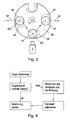
Der Aufbau und die Funktionsweise des Karussells 74 ist in
Unmittelbar unterhalb der drehbar oder schwenkbar gelagerten Platte 40 der Kugelführungseinheit 4 befindet sich eine Grundplatte 45. Im Bereich unmittelbar unterhalb des Einwurfkorbs 73 bzw. des Einlasses 73 befindet sich auf der Grundplatte 45 eine elastische Dämpfungseinheit 47, die die durch den Einwurfkorb 73 fallende Spielkugel 2 abbremst und dafür sorgt, dass die jeweilige Spielkugel 2 nicht beschädigt wird. In einer besonderen Ausführungsform der Erfindung ist vorgesehen, dass die elastische Dämpfungseinheit 47 durch ein Gummiband bzw. einen Gummipuffer ausgeführt ist, das unmittelbar unterhalb des Einwurfkorbs 73 auf der Grundplatte 45 angeordnet ist Das Gummiband ist dabei derart angeordnet, dass kein Tell der Spielkugel 2 beim unmittelbaren Auftreffen die Grundplatte 45 berührt. Nachdem der Fall der Spielkugel 2 abgebremst ist und diese in der Ausnehmung 44 der Platte 40 ruht und durch die Grundplatte 45 abgestützt ist, wird die Platte 40 rotiert und die in der Ausnehmung 44 befindliche Spielkugel 2 entlang eines vorgegebenen kreisförmigen Wegs 42 rotiert und/oder fortbewegt. Wie in
Das Karussell 74 ist von einem Motor 75, im vorliegenden Fall mit einem Schrittmotor 75, angetrieben, der sich unterhalb der Grundplatte 45 befindet und der mit der Grundplatte 45 verbunden ist.The
Alternativ kann auch vorgesehen sein, dass die Ausnehmungen 44 bis zum Rand der Platte 40 bzw. der Kugelführungseinheit 4 fortgesetzt ist, wie in
Der Rand der Ausnehmung der Platte 40 der Kugeiführungselnheit 4 bzw. des Karussells 74 verdeckt die ausgewählte Spielkugel 2 nicht einmal teilweise, sodass eine verbesserte Auswertung möglich ist. Die Darstellung unterschiedlicher Ausnehmungen 44 dient ledlglich der Illustration möglicher unterschiedlicher Arten der Führung der Spielkugel 2 im Karussell 74. Üblicherweise umfasst die Platte des Karussells 74 stets Ausnehmungen 44 derselben Form. Am Ende des vorgegebenen Wegs 42 ist in der Grundplatte 45 eine Ausnehmung 46 vorgesehen, durch die die Spielkugel 2 nach unten hindurchfallen kann. In diesem Ausführungsbeispiel ist diese Ausnehmung 46 kreisförmig ausgebildet. An diese Ausnehmung 46 schließt eine weitere Kugelführung 76 an, die die Spielkugel 2 an eine Hebevorrichtung 77 weitergibt.The edge of the recess of the
Die Hebevorrichtung 77 führt die Spielkugel 2, über eine weitere nicht dargestellte Kugelführung 2 wieder der Ziehung zu. Gegebenenfalls können die gezogenen Spielkugeln 2 bis zum Abschluss des jeweiligen Spiels zwischengelagert und erst nach Abschluss des Spiels wieder der Ziehung zugeführt werden, um die mehrfache Ziehung einer Spielkugel 2 während desselben Spiels zu verhindern.The lifting
Eine typische Spielkugel 2 ist in
Während sich die Spielkugel 2 im Aufnahmebereich der Bildaufnahmeeinheit 3 befindet, erstellt die Bildaufnahmeeinheit 3 laufend Aufnahmen der Spielkugel 2. In der vorteilhaften Ausgestaltung der Erfindung wird die Spielkugel 2 auf ihrem Weg in einer Position 421 im Aufnahmebereich der Bildaufnahmeeinheit 3 angehalten. Altemativ kann auch vorgesehen sein, dass die Bildaufnahmeeinheit 3 schwenkbar gelagert durch einen weiteren Motor ist und der Spielkugel 2 nachgeführt ist, wobei der Massenmittelpunkt M des Abbilds der Spielkugel 2 im Bild konstant gehalten wird. Zu diesem Zweck ist dem weiteren Motor (in der Fig. nicht dargestellt) eine Steuereinheit vorgeschaltet, die der Bildaufnahmeeinheit 3 nachgeschaltet ist und den weiteren Motor derart ansteuert, dass sich das Abbild der Spielkugel vollständig im Aufnahmebereich der Bildaufnahmeeinheit 3 befindet.While the
Die von der Bildaufnahmeeinheit 3 aufgenommenen Bilder werden zusätzlich auf einem den Spielern zugewandten, nicht dargestellten, Monitor dargestellt.The images taken by the
Eine Aufnahme einer Spielkugel 2 ist schematisch in
Zunächst wird die Bildposition des Abbilds 35 der Spielkugel 2 in dem von der Bildaufnahmeeinheit 3 erstellten Bild 300, dargestellt In
Beispielsweise kann die Spielkugel 2 zu diesem Zweck auf dem Weg 42 in eine Ausgangslage 422 (
Nachdem die Spielkugel 2 durch die Bildaufnahmeeinheit 3 vollständig erfasst worden ist, wird ein Identifikationsverfahren gestartet, das basierend auf dem von der Bildaufnahmeeinheit 3 erstellten Bild das auf der Spielkugel 2 abgebildete Symbol 21 ermittelt. In diesem besonderen Ausführungsbeispiel erstellt die Bildaufnahmeeinheit 3 Farbbilder (
In einem ersten Schritt wird mittels eines Detektionsverfahrens die Bildposition und die Größe des Kreises ermittelt und in Form der Mittelpunktskoordinaten xb, yb sowie des Durchmessers oder des Radius rb abgespeichert. Es wird der in
In einem weiteren Schritt wird die Verzerrung, die durch die sphärische Oberfläche der Spielkugeln 2 bewirkt wird durch eine Entzerrung behoben. Verfahren zur Entzerrung von auf einer Kugeloberfläche aufgedruckten Symbolen sind dem Fachmann aus dem Stand der Technik allgemein bekannt. Gegebenenfalls kann eine Kalibrierung stattfinden, mittels derer auf der Spielkugel 2 befindliche kreisförmige Bereiche einfach auf kreisförmige Bereiche des entzerrten Bilds abgebildet werden. Das Ergebnis der Entzerrung ist in
Weiters werden, wie in
Wie in
Für jeden der markierten Bildbereiche bzw. für jede der Masken 39 wird ein Markierungspunkt 38 ermittelt, der sich als Schnittpunkt der jeweiligen Abbilder 31, 32 der Markierungslinie 23 und der Hilfslinie 24 der jeweiligen Spielkugel 2 ergibt.
Anschließend werden die maskierten Bildbereiche einer Schwellenwertoperation unterzogen, wobei die einzelnen Helligkeitswerte der jeweiligen Pixel mit einem Schwellenwert verglichen werden und das Pixel im Falle des Unterschreitens des Schwellenwerts auf den Wert "Schwarz" bzur. "Null" gesetzt wird und im Falle des Überschreitens des Schwellenwerts auf "Weiß" bzw. "Eins" gesetzt wird.
Das Bilderkennungsverfahren kann gegebenenfalls mit einer Vielzahl unterschiedlicher zeitlich hinter einander von der Bildaufnahmeeinheit 3 ermittelter oder erstellter Bilder durchgeführt werden. Für jedes der Bilder wird separat das oben genannte Identifikationsverfahren durchgeführt und für jede einzelne Maske 39 erhält man Jewells ein Identifikationsresultat.If necessary, the image recognition method can be carried out with a multiplicity of different images determined or generated one after the other by the
Idealerweise erhält man identische Identifikationsresultate. Es kann jedoch bei nur schlecht sichtbaren, teilweise verdeckten oder stark verzerrten Bilderbeichen das Problem auftreten, dass eine eindeutige Identifikation des Jewelligen Symbols nicht möglich ist. In diesem Fall ist vorgesehen, dass eine Identifikation nur dann als korrekt erfolgt gilt, wenn mehr als die Hälfte der Identifikationsresultate identisch ist.Ideally, identical identification results are obtained. However, it can occur in poorly visible, partially hidden or heavily distorted Bildbeichen the problem that a clear identification of the Jewelligen symbol is not possible. In this case, it is provided that an identification is only considered to be correct if more than half of the identification results are identical.
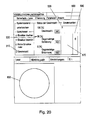
In den
Auf der linken Seite 400 wird ein Zahlenraster mit den Zahlen von eins bis neunzig angezeigt, wobei die letzt gezogene Nummer 429 farbig oder fett und die bereits gezogenen Nummern hell sind. Nicht gezogene Nummern werden grau angezeigt. Weiters wird die letzt gezogene Nummer in einem Feld 430 entweder als animierte Kugel dargestellt oder es wird das von der Blidaufnahmeeinheft 3 erstellte Bildsignal direkt als Live-Vdeo dargestellt.On the
Claims (18)
- A method of identifying a selected gaming ball (2) from a predefined number of gaming balls (2), each of the gaming balls (2) being provided with a symbol, which is different from the symbols of the other gaming balls (2),a) wherein the selected gaming ball (2) is moved from a starting position (422) through the acquisition area of an image recording unit (3),b) wherein the center of mass (M) of the image of the selected gaming ball (2) is maintained unaltered in the image (300) of the image recording unit (3) for a predefined period of time and does not perform a relative movement with respect to the image (300),c) wherein the image position and size of the image of the gaming ball (2) is determined and it is verified whether parts of the image of the gaming ball (2) are located outside a lateral edge predefined with respect to the image (300), and,d) if parts of the image (35) of the gaming ball (2) are outside of this lateral edge, the gaming ball (2) is shifted based on the calculated position along or opposite the progressing direction of the path (42) of the gaming ball (2) and brought back to the acquisition area of the image recording unit (3) and repositioned, and steps b) to d) are repeated, ande) based on at least one image (300) recorded with the image recording unit (3), a method of identifying is conducted and an identification result is determined that corresponds to, or is unambiguously associated with, the symbol on the surface of the selected gaming ball (2).
- The method in accordance with Claim 1, characterized in that, for fixing the center of mass of the depiction of the selected gaming ball (2) in the image (300) of the image recording unit (3), the gaming ball (2) is stopped and remains motionless with respect to the image recording unit (3).
- The method in accordance with Claim 1 or 2, characterized in that the gaming ball (2) is moved from the starting position (41) along a predefined path (42) through the acquisition area of the image recording unit (3) by a ball guiding unit (4), wherein the respective selected gaming ball (2) is removed from the ball guiding unit (4) after moving on its predefined path (42) and optionally forwarded.
- The method in accordance with Claim 3, characterized in that the selected gaming ball (2) is moved forward on the predefined path (42) in the form of a circular arc on a horizontal plane, wherein the recording direction or line of sight of the image recording unit (3) is essentially horizontal and preferably directed to a spot on the predefined path (42) in which the gaming ball (2) is closest to the image recording unit (3).
- The method in accordance with any one of Claims 3 or 4, characterized in that the gaming ball (2) is received by a circular recess (44) of the ball guiding unit (4), which is essentially designed to be flat and discoid, and is secured against rolling away laterally, whereina) the gaming ball (2) is tossed into and/or falls onto the circular recess (44) from above and wherein the fall of the gaming ball (2) is decelerated, in particular by an elastic damping unit (47) disposed below the recess (44), and/orb) the gaming ball (2) is guided and/or rotated in the recess (44) of the ball guiding unit (4) and supported on a base plate (45) located beneath the discoid ball guiding unit (4), and/orc) the gaming ball (2) falls through a recess (46) located in the base plate (45) and/or located beneath the ball guiding unit and is transported further.
- The method in accordance with any one of the preceding claims, characterized in that the image recording unit (3) permanently produces images (300) in predefined time intervals and that these images (300) are preferably shown on a monitor so to be visible for the players.
- The method in accordance with any one of the preceding claims, characterized in that, during the predefined period, a number of, in particular four, images (300) is produced and identification of the gaming ball (2) takes place based on at least two of images (300) recorded at different time points, wherein identification is done separately for each of the images (300) and wherein each identification of an image (300) delivers a separate identification result.
- The method in accordance with any one of the preceding claims, characterized in that an identification result is determined based on a recorded image (300), wherein symbols of writing are used as symbols and wherein symbols (21) of writing arranged in circles (22) are arranged on the gaming balls (2), and wherein a marking line (23) representing the direction of writing is provided, which is, in particular, arranged below in writing direction and equally represents an underline under the respective symbol (21) of writing, wherein the marking line (23) is, in particular, connected to the circle (22), in particular via an auxiliary line (24), bya) finding areas of the image of the gaming ball (2) and saving them as recognition areas, which are limited by an, in particular solid, circular line,b) for all areas limited by circular edges that were found, determining the orientation of the symbol located within the area, rotating the found image areas according to their orientation so that the determined symbols are each uniformly orientated, andc) first filtering the symbols of writing located in the oriented and/or rotated areas and then subjecting them to a symbol recognition procedure and, for each of the oriented areas, determining an identification result representing the respective symbol.
- The method in accordance with Claim 8, characterized in that for all areas limited by circular edges that were found, the orientation of the symbol located within the area is determined by finding the image of a marking line abutting, or connected to, the circular line and determining its orientation.
- The method in accordance with Claim 8 or 9, characterized in that the image areas are scaled to a predefined dimension after being oriented.
- The method in accordance with Claim 8, 9 or 10, characterized in that, in the case of differing identification results for multiple areas, that identification result is considered to be determined which has been recognized for the majority of areas.
- A device for identifying a selected gaming ball (2) from a predefined number of gaming balls (2), each of the gaming balls (2) being provided with a symbol, which is different from the symbols of the other gaming balls (2),a) comprising an image recording unit (3), which has an acquisition area,b) comprising means (74, 75) of moving the selected gaming ball (2) from a starting position through the acquisition area of the image recording unit (3),c) comprising an examining unit for examining the position and size of the image of the gaming ball (2) as well as for producing a positioning signal in case parts of the image of the gaming ball (2) are located outside a lateral edge predefined with respect to the image, and,d) a positioning unit downstream of the examining unit, which causes the means (74, 75) for moving the selected gaming ball (2) to a new position and/or to reposition the gaming ball (2) in its entrance if a positioning signal is present, wherein the device is configured to shift the gaming ball (2) based on the calculated position along or against the progressing direction of the path (42) of the gaming ball (2), ande) an identifying unit for identifying symbols (21) located on the gaming balls (2) based on at least one image (300) recorded by means of the image recording unit (3), at the output of which there is an identification result that corresponds to, or is unambiguously associated with, the symbol (21) on the surface of the selected gaming ball (2).
- The device in accordance with Claim 12, characterized by a control unit, which, in order to fix the center of mass (M) of the image (35) of the selected gaming ball (2) in the image of the image recording unit (3), stops or inactivates the means (75, 40, 44, 45) for moving the gaming ball (2) so that the gaming ball (2) remains motionless with respect to the image recording unit (3).
- The device in accordance with Claim 12 or 13, characterized in that a ball guiding unit (4) is provided, by which the gaming ball (2) can be moved from the starting position (422) along a predefined path (42) through the acquisition area of the image recording unit (3), wherein the respective selected gaming ball (2) falls out of the ball guiding unit (4) after being moved via the predefined path (42).
- The device in accordance with Claim 14, characterized in that the ball guiding unit (4) is designed to be a flat, in particular transparent, thin disc, in particular a circular disc, which has at least one eccentrically arranged, in particular circular, recess (44) for receiving the gaming ball (2), wherein the disc of the ball guiding unit (4) is arranged horizontally and rotatably and/or pivotably supported around a center of gravity, in particular the center point of the circular disc, and wherein the recording direction or line of sight of the image recording unit (3) is essentially horizontal and preferably directed to a spot (421) on the predefined path (42) in which the gaming ball (2) is closest to the image recording unit (3).
- The device in accordance with Claim 15, characterized in thata) an inlet (73) is provided, which is located immediately above a spot on the predefined path (42), wherein an elastic damping unit (47) for decelerating a gaming ball (2) is provided in particular immediately beneath the inlet (73), and/orb) a base plate (45) for supporting and guiding the gaming balls (2) is provided beneath the discoid ball guiding unit (4), and/orc) a recess (46) having the size of a gaming ball (2) is provided at the end of the path (42), in particular in the base plate (45), so that a gaming ball (2) can fall through said recess (46).
- The device in accordance with Claim 15 or 16, characterized in that the recess (44) of the ball guiding unit (4) is continued until the edge of the ball guiding unit (4) and that a hemisphere of the gaming ball (2) is depicted in its entirety by the image recording unit (3) and in particular not obscured by the ball guiding unit (4) in at least on position on the path (42).
- The device in accordance with any one of Claims 12 to 17, characterized by a monitor which shows images (300) permanently recorded by the image recording unit (3) in predefined time intervals.
Priority Applications (13)
| Application Number | Priority Date | Filing Date | Title |
|---|---|---|---|
| PL11450010T PL2535875T3 (en) | 2011-01-21 | 2011-01-21 | Method and device for identifying game balls |
| EP11450010.1A EP2535875B1 (en) | 2011-01-21 | 2011-01-21 | Method and device for identifying game balls |
| ES11450010.1T ES2473140T3 (en) | 2011-01-21 | 2011-01-21 | Procedure for the identification of a game ball |
| MX2013008380A MX345931B (en) | 2011-01-21 | 2012-01-23 | Method and apparatus for identifying playing balls. |
| RU2013134642/12A RU2591093C2 (en) | 2011-01-21 | 2012-01-23 | Method and device for identification of game balls |
| PCT/IB2012/050309 WO2012098535A1 (en) | 2011-01-21 | 2012-01-23 | Method and apparatus for identifying playing balls |
| US13/980,487 US9251415B2 (en) | 2011-01-21 | 2012-01-23 | Method and apparatus for identifying symbol bearing gaming balls |
| CN201280005870.7A CN103392193B (en) | 2011-01-21 | 2012-01-23 | For the method and apparatus identifying lot cast ball |
| SG2013055306A SG192050A1 (en) | 2011-01-21 | 2012-01-23 | Method and apparatus for identifying playing balls |
| CA2824555A CA2824555C (en) | 2011-01-21 | 2012-01-23 | Method and apparatus for identifying symbol bearing gaming balls |
| AP2013007018A AP4053A (en) | 2011-01-21 | 2012-01-23 | Method and apparatus for identifying playing balls |
| AU2012208275A AU2012208275B2 (en) | 2011-01-21 | 2012-01-23 | Method and apparatus for identifying playing balls |
| ZA2013/05530A ZA201305530B (en) | 2011-01-21 | 2013-07-22 | Method and apparatus for identifying playing balls |
Applications Claiming Priority (1)
| Application Number | Priority Date | Filing Date | Title |
|---|---|---|---|
| EP11450010.1A EP2535875B1 (en) | 2011-01-21 | 2011-01-21 | Method and device for identifying game balls |
Publications (2)
| Publication Number | Publication Date |
|---|---|
| EP2535875A1 EP2535875A1 (en) | 2012-12-19 |
| EP2535875B1 true EP2535875B1 (en) | 2014-05-07 |
Family
ID=45581941
Family Applications (1)
| Application Number | Title | Priority Date | Filing Date |
|---|---|---|---|
| EP11450010.1A Active EP2535875B1 (en) | 2011-01-21 | 2011-01-21 | Method and device for identifying game balls |
Country Status (13)
| Country | Link |
|---|---|
| US (1) | US9251415B2 (en) |
| EP (1) | EP2535875B1 (en) |
| CN (1) | CN103392193B (en) |
| AP (1) | AP4053A (en) |
| AU (1) | AU2012208275B2 (en) |
| CA (1) | CA2824555C (en) |
| ES (1) | ES2473140T3 (en) |
| MX (1) | MX345931B (en) |
| PL (1) | PL2535875T3 (en) |
| RU (1) | RU2591093C2 (en) |
| SG (1) | SG192050A1 (en) |
| WO (1) | WO2012098535A1 (en) |
| ZA (1) | ZA201305530B (en) |
Families Citing this family (7)
| Publication number | Priority date | Publication date | Assignee | Title |
|---|---|---|---|---|
| JP2017509459A (en) * | 2014-03-21 | 2017-04-06 | エフゲニエヴィチ コレソフ,アンドレイ | Lottery equipment |
| WO2015197881A1 (en) * | 2014-06-26 | 2015-12-30 | Recreativos Franco, S.A. | Recreational machine |
| US9751002B2 (en) * | 2015-06-23 | 2017-09-05 | Alan Frank | Random digit generator featuring differently colored balls |
| KR20180002408A (en) * | 2016-06-29 | 2018-01-08 | 주식회사 크리에이츠 | Method, system and non-transitory computer-readable recording medium for measuring ball spin |
| US10803702B1 (en) * | 2016-11-15 | 2020-10-13 | Toan Phan | Card selection system for online game play |
| CN110969754B (en) * | 2019-11-26 | 2021-11-16 | 广州腾顺信息科技有限公司 | Extraction device for generating random result, drawing machine and drawing method |
| CN111757147B (en) * | 2020-06-03 | 2022-06-24 | 苏宁云计算有限公司 | Method, device and system for event video structuring |
Family Cites Families (13)
| Publication number | Priority date | Publication date | Assignee | Title |
|---|---|---|---|---|
| SU24338A1 (en) * | 1929-05-10 | 1931-11-30 | И.В. Андреев | Lottery machine |
| FR2577429B1 (en) * | 1985-02-18 | 1987-07-31 | Ryo Catteau Sa Ste Nle Ets | GAME BALL |
| JPH08280902A (en) | 1995-04-19 | 1996-10-29 | Heiwa Corp | Pinball clogging liminating device of pinball machine |
| US6080061A (en) * | 1996-09-05 | 2000-06-27 | Konami Co., Ltd. | Game machine for randomly selected information comparison with sets of selected, randomly selected and correlated information |
| DE20005276U1 (en) * | 1999-03-20 | 2000-08-03 | Cho Kun Lin | Automatic evaluation device and ball dispenser |
| ES2163377B2 (en) * | 2000-06-01 | 2003-06-16 | F B Tecnicos Asoc S A | SYSTEM FOR READING AND CHECKING BALLS IN THE GAME OF BINGO. |
| US20040256800A1 (en) | 2003-04-09 | 2004-12-23 | Arrow International, Inc. | Game console with random selection device |
| JP2005192606A (en) * | 2003-12-26 | 2005-07-21 | Aruze Corp | Game machine |
| US20060105833A1 (en) * | 2004-11-17 | 2006-05-18 | Yueh-Chun Lin | Method for assembling a game-selected drawing machine |
| US7244198B2 (en) | 2005-03-02 | 2007-07-17 | Hadi Morshed | Tennis ball delivery device |
| US7775521B1 (en) * | 2007-03-05 | 2010-08-17 | Fortunet, Inc. | Smart ball blower |
| JP4375490B2 (en) | 2008-07-09 | 2009-12-02 | 株式会社三洋物産 | Game machine |
| EA013711B1 (en) * | 2008-12-05 | 2010-06-30 | Общество С Ограниченной Ответственностью "Центр Разработки И Внедрения Инновационных Технологий" | Method for holding a lottery |
-
2011
- 2011-01-21 PL PL11450010T patent/PL2535875T3/en unknown
- 2011-01-21 ES ES11450010.1T patent/ES2473140T3/en active Active
- 2011-01-21 EP EP11450010.1A patent/EP2535875B1/en active Active
-
2012
- 2012-01-23 US US13/980,487 patent/US9251415B2/en not_active Expired - Fee Related
- 2012-01-23 RU RU2013134642/12A patent/RU2591093C2/en active
- 2012-01-23 CN CN201280005870.7A patent/CN103392193B/en not_active Expired - Fee Related
- 2012-01-23 WO PCT/IB2012/050309 patent/WO2012098535A1/en active Application Filing
- 2012-01-23 MX MX2013008380A patent/MX345931B/en active IP Right Grant
- 2012-01-23 CA CA2824555A patent/CA2824555C/en not_active Expired - Fee Related
- 2012-01-23 SG SG2013055306A patent/SG192050A1/en unknown
- 2012-01-23 AU AU2012208275A patent/AU2012208275B2/en not_active Ceased
- 2012-01-23 AP AP2013007018A patent/AP4053A/en active
-
2013
- 2013-07-22 ZA ZA2013/05530A patent/ZA201305530B/en unknown
Also Published As
| Publication number | Publication date |
|---|---|
| AP4053A (en) | 2017-03-07 |
| RU2591093C2 (en) | 2016-07-10 |
| ZA201305530B (en) | 2014-10-29 |
| MX2013008380A (en) | 2014-01-20 |
| CN103392193A (en) | 2013-11-13 |
| EP2535875A1 (en) | 2012-12-19 |
| CA2824555C (en) | 2019-03-12 |
| AP2013007018A0 (en) | 2013-07-31 |
| SG192050A1 (en) | 2013-08-30 |
| RU2013134642A (en) | 2015-02-27 |
| CA2824555A1 (en) | 2012-07-26 |
| AU2012208275B2 (en) | 2016-04-14 |
| MX345931B (en) | 2014-12-02 |
| PL2535875T3 (en) | 2014-08-29 |
| CN103392193B (en) | 2016-11-16 |
| US9251415B2 (en) | 2016-02-02 |
| WO2012098535A1 (en) | 2012-07-26 |
| AU2012208275A1 (en) | 2013-08-01 |
| ES2473140T3 (en) | 2014-07-03 |
| US20140029795A1 (en) | 2014-01-30 |
Similar Documents
| Publication | Publication Date | Title |
|---|---|---|
| EP2535875B1 (en) | Method and device for identifying game balls | |
| DE102012110375B4 (en) | A method and apparatus for decoding object-applied codes for use with an image sensor incorporating a two-dimensional field of view | |
| DE602005002383T2 (en) | Method, arrangement and gaming device for determining the number of points of a dice. | |
| DE19842161C1 (en) | Arrangement for automatically detecting the number of dots on the upper side of a dice esp. for the game of craps | |
| DE60302549T2 (en) | RECOGNITION OF GAME INFORMATION | |
| DE2831582C2 (en) | Method for identifying a person and device for carrying out the method | |
| DE60212473T2 (en) | Code reader and entertainment system | |
| WO2002077907A1 (en) | Method for guiding the user of a biometric system having fingerprint input | |
| DE212013000203U1 (en) | Improvements regarding ticketing data entry | |
| AT518890B1 (en) | Bending machine with a workspace image capture device | |
| DE102015205225A1 (en) | Method and device for detecting a target object in the blind spot of a vehicle | |
| DE102012108838A1 (en) | Method and device for recording fingerprints based on fingerprint scanners in reliably high quality | |
| EP3244379A1 (en) | System and method for collection and analysis of video data relating to the course of the game on a gambling table in casinos | |
| DE10100615A1 (en) | Hand recognition with position determination | |
| DE102019106520A1 (en) | Parking assistance device, parking assistance method and parking assistance program | |
| WO2019015851A1 (en) | Method and device for identifying damage to vehicle panes | |
| DE102013005489A1 (en) | Method and device for the automatic detection of defects in limp bodies | |
| DE102019218969A1 (en) | CENTER DETECTION METHOD | |
| DE69834119T2 (en) | IMAGE ANALYSIS SYSTEMS AND APPROPRIATE APPARATUS | |
| AT519722B1 (en) | Method for the detection of at least one token object | |
| WO2018082745A1 (en) | Method and apparatus for determining the precise spatial orientation of arrow-like objects relative to surfaces | |
| EP3200154B1 (en) | Method for determining a position of an object | |
| DE102016114745A1 (en) | Systems and methods for sorting image capture settings for pattern stitching and decoding using multiple captured images | |
| DE102022124736B3 (en) | Gate arrangement, especially for a passenger transport system | |
| DE102008017233A1 (en) | Reverse vending machine |
Legal Events
| Date | Code | Title | Description |
|---|---|---|---|
| PUAI | Public reference made under article 153(3) epc to a published international application that has entered the european phase |
Free format text: ORIGINAL CODE: 0009012 |
|
| 17P | Request for examination filed |
Effective date: 20110812 |
|
| AK | Designated contracting states |
Kind code of ref document: A1 Designated state(s): AL AT BE BG CH CY CZ DE DK EE ES FI FR GB GR HR HU IE IS IT LI LT LU LV MC MK MT NL NO PL PT RO RS SE SI SK SM TR |
|
| AX | Request for extension of the european patent |
Extension state: BA ME |
|
| GRAP | Despatch of communication of intention to grant a patent |
Free format text: ORIGINAL CODE: EPIDOSNIGR1 |
|
| INTG | Intention to grant announced |
Effective date: 20131122 |
|
| GRAS | Grant fee paid |
Free format text: ORIGINAL CODE: EPIDOSNIGR3 |
|
| GRAA | (expected) grant |
Free format text: ORIGINAL CODE: 0009210 |
|
| AK | Designated contracting states |
Kind code of ref document: B1 Designated state(s): AL AT BE BG CH CY CZ DE DK EE ES FI FR GB GR HR HU IE IS IT LI LT LU LV MC MK MT NL NO PL PT RO RS SE SI SK SM TR |
|
| REG | Reference to a national code |
Ref country code: GB Ref legal event code: FG4D Free format text: NOT ENGLISH |
|
| REG | Reference to a national code |
Ref country code: AT Ref legal event code: REF Ref document number: 667190 Country of ref document: AT Kind code of ref document: T Effective date: 20140515 |
|
| REG | Reference to a national code |
Ref country code: IE Ref legal event code: FG4D Free format text: LANGUAGE OF EP DOCUMENT: GERMAN |
|
| REG | Reference to a national code |
Ref country code: DE Ref legal event code: R096 Ref document number: 502011003003 Country of ref document: DE Effective date: 20140618 |
|
| REG | Reference to a national code |
Ref country code: ES Ref legal event code: FG2A Ref document number: 2473140 Country of ref document: ES Kind code of ref document: T3 Effective date: 20140703 |
|
| REG | Reference to a national code |
Ref country code: PL Ref legal event code: T3 |
|
| REG | Reference to a national code |
Ref country code: SK Ref legal event code: T3 Ref document number: E 16487 Country of ref document: SK |
|
| REG | Reference to a national code |
Ref country code: NL Ref legal event code: VDEP Effective date: 20140507 |
|
| REG | Reference to a national code |
Ref country code: LT Ref legal event code: MG4D |
|
| PG25 | Lapsed in a contracting state [announced via postgrant information from national office to epo] |
Ref country code: IS Free format text: LAPSE BECAUSE OF FAILURE TO SUBMIT A TRANSLATION OF THE DESCRIPTION OR TO PAY THE FEE WITHIN THE PRESCRIBED TIME-LIMIT Effective date: 20140907 Ref country code: NO Free format text: LAPSE BECAUSE OF FAILURE TO SUBMIT A TRANSLATION OF THE DESCRIPTION OR TO PAY THE FEE WITHIN THE PRESCRIBED TIME-LIMIT Effective date: 20140807 Ref country code: FI Free format text: LAPSE BECAUSE OF FAILURE TO SUBMIT A TRANSLATION OF THE DESCRIPTION OR TO PAY THE FEE WITHIN THE PRESCRIBED TIME-LIMIT Effective date: 20140507 Ref country code: CY Free format text: LAPSE BECAUSE OF FAILURE TO SUBMIT A TRANSLATION OF THE DESCRIPTION OR TO PAY THE FEE WITHIN THE PRESCRIBED TIME-LIMIT Effective date: 20140507 Ref country code: GR Free format text: LAPSE BECAUSE OF FAILURE TO SUBMIT A TRANSLATION OF THE DESCRIPTION OR TO PAY THE FEE WITHIN THE PRESCRIBED TIME-LIMIT Effective date: 20140808 Ref country code: LT Free format text: LAPSE BECAUSE OF FAILURE TO SUBMIT A TRANSLATION OF THE DESCRIPTION OR TO PAY THE FEE WITHIN THE PRESCRIBED TIME-LIMIT Effective date: 20140507 |
|
| PG25 | Lapsed in a contracting state [announced via postgrant information from national office to epo] |
Ref country code: SE Free format text: LAPSE BECAUSE OF FAILURE TO SUBMIT A TRANSLATION OF THE DESCRIPTION OR TO PAY THE FEE WITHIN THE PRESCRIBED TIME-LIMIT Effective date: 20140507 Ref country code: HR Free format text: LAPSE BECAUSE OF FAILURE TO SUBMIT A TRANSLATION OF THE DESCRIPTION OR TO PAY THE FEE WITHIN THE PRESCRIBED TIME-LIMIT Effective date: 20140507 Ref country code: RS Free format text: LAPSE BECAUSE OF FAILURE TO SUBMIT A TRANSLATION OF THE DESCRIPTION OR TO PAY THE FEE WITHIN THE PRESCRIBED TIME-LIMIT Effective date: 20140507 Ref country code: LV Free format text: LAPSE BECAUSE OF FAILURE TO SUBMIT A TRANSLATION OF THE DESCRIPTION OR TO PAY THE FEE WITHIN THE PRESCRIBED TIME-LIMIT Effective date: 20140507 |
|
| PG25 | Lapsed in a contracting state [announced via postgrant information from national office to epo] |
Ref country code: PT Free format text: LAPSE BECAUSE OF FAILURE TO SUBMIT A TRANSLATION OF THE DESCRIPTION OR TO PAY THE FEE WITHIN THE PRESCRIBED TIME-LIMIT Effective date: 20140908 |
|
| PG25 | Lapsed in a contracting state [announced via postgrant information from national office to epo] |
Ref country code: EE Free format text: LAPSE BECAUSE OF FAILURE TO SUBMIT A TRANSLATION OF THE DESCRIPTION OR TO PAY THE FEE WITHIN THE PRESCRIBED TIME-LIMIT Effective date: 20140507 Ref country code: RO Free format text: LAPSE BECAUSE OF FAILURE TO SUBMIT A TRANSLATION OF THE DESCRIPTION OR TO PAY THE FEE WITHIN THE PRESCRIBED TIME-LIMIT Effective date: 20140507 Ref country code: DK Free format text: LAPSE BECAUSE OF FAILURE TO SUBMIT A TRANSLATION OF THE DESCRIPTION OR TO PAY THE FEE WITHIN THE PRESCRIBED TIME-LIMIT Effective date: 20140507 |
|
| REG | Reference to a national code |
Ref country code: DE Ref legal event code: R097 Ref document number: 502011003003 Country of ref document: DE |
|
| PG25 | Lapsed in a contracting state [announced via postgrant information from national office to epo] |
Ref country code: NL Free format text: LAPSE BECAUSE OF FAILURE TO SUBMIT A TRANSLATION OF THE DESCRIPTION OR TO PAY THE FEE WITHIN THE PRESCRIBED TIME-LIMIT Effective date: 20140507 |
|
| PLBE | No opposition filed within time limit |
Free format text: ORIGINAL CODE: 0009261 |
|
| STAA | Information on the status of an ep patent application or granted ep patent |
Free format text: STATUS: NO OPPOSITION FILED WITHIN TIME LIMIT |
|
| 26N | No opposition filed |
Effective date: 20150210 |
|
| REG | Reference to a national code |
Ref country code: DE Ref legal event code: R097 Ref document number: 502011003003 Country of ref document: DE Effective date: 20150210 |
|
| PG25 | Lapsed in a contracting state [announced via postgrant information from national office to epo] |
Ref country code: BE Free format text: LAPSE BECAUSE OF NON-PAYMENT OF DUE FEES Effective date: 20150131 |
|
| PG25 | Lapsed in a contracting state [announced via postgrant information from national office to epo] |
Ref country code: SI Free format text: LAPSE BECAUSE OF FAILURE TO SUBMIT A TRANSLATION OF THE DESCRIPTION OR TO PAY THE FEE WITHIN THE PRESCRIBED TIME-LIMIT Effective date: 20140507 |
|
| REG | Reference to a national code |
Ref country code: CH Ref legal event code: PL |
|
| PG25 | Lapsed in a contracting state [announced via postgrant information from national office to epo] |
Ref country code: LU Free format text: LAPSE BECAUSE OF FAILURE TO SUBMIT A TRANSLATION OF THE DESCRIPTION OR TO PAY THE FEE WITHIN THE PRESCRIBED TIME-LIMIT Effective date: 20150121 |
|
| PG25 | Lapsed in a contracting state [announced via postgrant information from national office to epo] |
Ref country code: MC Free format text: LAPSE BECAUSE OF FAILURE TO SUBMIT A TRANSLATION OF THE DESCRIPTION OR TO PAY THE FEE WITHIN THE PRESCRIBED TIME-LIMIT Effective date: 20140507 |
|
| PG25 | Lapsed in a contracting state [announced via postgrant information from national office to epo] |
Ref country code: LI Free format text: LAPSE BECAUSE OF NON-PAYMENT OF DUE FEES Effective date: 20150131 Ref country code: CH Free format text: LAPSE BECAUSE OF NON-PAYMENT OF DUE FEES Effective date: 20150131 |
|
| REG | Reference to a national code |
Ref country code: IE Ref legal event code: MM4A |
|
| REG | Reference to a national code |
Ref country code: FR Ref legal event code: PLFP Year of fee payment: 6 |
|
| PG25 | Lapsed in a contracting state [announced via postgrant information from national office to epo] |
Ref country code: IE Free format text: LAPSE BECAUSE OF NON-PAYMENT OF DUE FEES Effective date: 20150121 |
|
| PG25 | Lapsed in a contracting state [announced via postgrant information from national office to epo] |
Ref country code: MT Free format text: LAPSE BECAUSE OF FAILURE TO SUBMIT A TRANSLATION OF THE DESCRIPTION OR TO PAY THE FEE WITHIN THE PRESCRIBED TIME-LIMIT Effective date: 20140507 |
|
| REG | Reference to a national code |
Ref country code: FR Ref legal event code: PLFP Year of fee payment: 7 |
|
| PG25 | Lapsed in a contracting state [announced via postgrant information from national office to epo] |
Ref country code: SM Free format text: LAPSE BECAUSE OF FAILURE TO SUBMIT A TRANSLATION OF THE DESCRIPTION OR TO PAY THE FEE WITHIN THE PRESCRIBED TIME-LIMIT Effective date: 20140507 Ref country code: BG Free format text: LAPSE BECAUSE OF FAILURE TO SUBMIT A TRANSLATION OF THE DESCRIPTION OR TO PAY THE FEE WITHIN THE PRESCRIBED TIME-LIMIT Effective date: 20140507 Ref country code: HU Free format text: LAPSE BECAUSE OF FAILURE TO SUBMIT A TRANSLATION OF THE DESCRIPTION OR TO PAY THE FEE WITHIN THE PRESCRIBED TIME-LIMIT; INVALID AB INITIO Effective date: 20110121 |
|
| PG25 | Lapsed in a contracting state [announced via postgrant information from national office to epo] |
Ref country code: TR Free format text: LAPSE BECAUSE OF FAILURE TO SUBMIT A TRANSLATION OF THE DESCRIPTION OR TO PAY THE FEE WITHIN THE PRESCRIBED TIME-LIMIT Effective date: 20140507 |
|
| REG | Reference to a national code |
Ref country code: FR Ref legal event code: PLFP Year of fee payment: 8 |
|
| PG25 | Lapsed in a contracting state [announced via postgrant information from national office to epo] |
Ref country code: MK Free format text: LAPSE BECAUSE OF FAILURE TO SUBMIT A TRANSLATION OF THE DESCRIPTION OR TO PAY THE FEE WITHIN THE PRESCRIBED TIME-LIMIT Effective date: 20140507 |
|
| REG | Reference to a national code |
Ref country code: DE Ref legal event code: R082 Ref document number: 502011003003 Country of ref document: DE Representative=s name: FLACH BAUER & PARTNER PATENTANWAELTE MBB, DE Ref country code: DE Ref legal event code: R082 Ref document number: 502011003003 Country of ref document: DE Representative=s name: FLACH BAUER STAHL PATENTANWAELTE PARTNERSCHAFT, DE |
|
| PG25 | Lapsed in a contracting state [announced via postgrant information from national office to epo] |
Ref country code: AL Free format text: LAPSE BECAUSE OF FAILURE TO SUBMIT A TRANSLATION OF THE DESCRIPTION OR TO PAY THE FEE WITHIN THE PRESCRIBED TIME-LIMIT Effective date: 20140507 |
|
| PGFP | Annual fee paid to national office [announced via postgrant information from national office to epo] |
Ref country code: CZ Payment date: 20210108 Year of fee payment: 11 Ref country code: FR Payment date: 20210121 Year of fee payment: 11 Ref country code: IT Payment date: 20210129 Year of fee payment: 11 |
|
| PGFP | Annual fee paid to national office [announced via postgrant information from national office to epo] |
Ref country code: AT Payment date: 20210119 Year of fee payment: 11 Ref country code: ES Payment date: 20210217 Year of fee payment: 11 Ref country code: GB Payment date: 20210122 Year of fee payment: 11 Ref country code: DE Payment date: 20210120 Year of fee payment: 11 |
|
| PGFP | Annual fee paid to national office [announced via postgrant information from national office to epo] |
Ref country code: SK Payment date: 20210108 Year of fee payment: 11 |
|
| REG | Reference to a national code |
Ref country code: DE Ref legal event code: R119 Ref document number: 502011003003 Country of ref document: DE |
|
| REG | Reference to a national code |
Ref country code: SK Ref legal event code: MM4A Ref document number: E 16487 Country of ref document: SK Effective date: 20220121 |
|
| REG | Reference to a national code |
Ref country code: AT Ref legal event code: MM01 Ref document number: 667190 Country of ref document: AT Kind code of ref document: T Effective date: 20220121 |
|
| GBPC | Gb: european patent ceased through non-payment of renewal fee |
Effective date: 20220121 |
|
| PG25 | Lapsed in a contracting state [announced via postgrant information from national office to epo] |
Ref country code: SK Free format text: LAPSE BECAUSE OF NON-PAYMENT OF DUE FEES Effective date: 20220121 Ref country code: GB Free format text: LAPSE BECAUSE OF NON-PAYMENT OF DUE FEES Effective date: 20220121 Ref country code: DE Free format text: LAPSE BECAUSE OF NON-PAYMENT OF DUE FEES Effective date: 20220802 Ref country code: CZ Free format text: LAPSE BECAUSE OF NON-PAYMENT OF DUE FEES Effective date: 20220121 Ref country code: AT Free format text: LAPSE BECAUSE OF NON-PAYMENT OF DUE FEES Effective date: 20220121 |
|
| PG25 | Lapsed in a contracting state [announced via postgrant information from national office to epo] |
Ref country code: FR Free format text: LAPSE BECAUSE OF NON-PAYMENT OF DUE FEES Effective date: 20220131 |
|
| PG25 | Lapsed in a contracting state [announced via postgrant information from national office to epo] |
Ref country code: IT Free format text: LAPSE BECAUSE OF NON-PAYMENT OF DUE FEES Effective date: 20220121 |
|
| REG | Reference to a national code |
Ref country code: ES Ref legal event code: FD2A Effective date: 20230329 |
|
| PG25 | Lapsed in a contracting state [announced via postgrant information from national office to epo] |
Ref country code: ES Free format text: LAPSE BECAUSE OF NON-PAYMENT OF DUE FEES Effective date: 20220122 |