EP2535307B1 - Permanentmagnethebevorrichtung - Google Patents
Permanentmagnethebevorrichtung Download PDFInfo
- Publication number
- EP2535307B1 EP2535307B1 EP10845435.6A EP10845435A EP2535307B1 EP 2535307 B1 EP2535307 B1 EP 2535307B1 EP 10845435 A EP10845435 A EP 10845435A EP 2535307 B1 EP2535307 B1 EP 2535307B1
- Authority
- EP
- European Patent Office
- Prior art keywords
- magnet
- turnable
- pole
- handle
- retaining pin
- Prior art date
- Legal status (The legal status is an assumption and is not a legal conclusion. Google has not performed a legal analysis and makes no representation as to the accuracy of the status listed.)
- Active
Links
Images


Classifications
-
- B—PERFORMING OPERATIONS; TRANSPORTING
- B66—HOISTING; LIFTING; HAULING
- B66C—CRANES; LOAD-ENGAGING ELEMENTS OR DEVICES FOR CRANES, CAPSTANS, WINCHES, OR TACKLES
- B66C1/00—Load-engaging elements or devices attached to lifting or lowering gear of cranes or adapted for connection therewith for transmitting lifting forces to articles or groups of articles
- B66C1/04—Load-engaging elements or devices attached to lifting or lowering gear of cranes or adapted for connection therewith for transmitting lifting forces to articles or groups of articles by magnetic means
-
- H—ELECTRICITY
- H01—ELECTRIC ELEMENTS
- H01F—MAGNETS; INDUCTANCES; TRANSFORMERS; SELECTION OF MATERIALS FOR THEIR MAGNETIC PROPERTIES
- H01F7/00—Magnets
- H01F7/02—Permanent magnets [PM]
-
- H—ELECTRICITY
- H01—ELECTRIC ELEMENTS
- H01F—MAGNETS; INDUCTANCES; TRANSFORMERS; SELECTION OF MATERIALS FOR THEIR MAGNETIC PROPERTIES
- H01F7/00—Magnets
- H01F7/02—Permanent magnets [PM]
- H01F7/0231—Magnetic circuits with PM for power or force generation
- H01F7/0252—PM holding devices
- H01F7/0257—Lifting, pick-up magnetic objects
Definitions
- the present invention relates to a kind of permanent magnetic lifting device, and more specifically, to a kind of permanent magnetic lifting device, which has a housing, a fixed magnet(s), and a turnable magnet, and is able to clamp objects with a clamping surface.
- a permanent magnetic lifting device has a nominal lifting capacity of 250 kg, its maximum clamping force can be 750 kg under ideal conditions, that is, the maximum clamping force generated under ideal conditions can be 3 times nominal lifting capacity. This is what we call safe lifting coefficient. Because the maximum clamping force that can be generated by a permanent magnetic lifting device relates to many factors, such as the material, dimension, and surface condition of a workpiece, and the size of contact area between a workpiece and a permanent magnetic lifting device, the maximum clamping force that can be generated by a permanent magnetic lifting device may be different under each specific condition.
- a permanent magnetic lifting device with the nominal lifting capacity of 250 kg may generate a maximum lifting force lower than 250 kg under a certain condition. Because an operator has no way to know the maximum clamping force that can be generated by a permanent magnetic lifting device with a certain nominal lifting capacity, even though a workpiece weighs less than nominal lifting capacity, and the workpiece can be lifted up, its safe running is not assured. This is because that the lifting device may be in the critical condition that the workpiece is just lifted up, with external force resulted from acceleration in traveling of the workpiece, the workpiece may fall, resulting in a potential risk in safety.
- Magnetic lifting devices are know from JP S47 34963 U , KR 100 602 514 B1 , ES 2 273 551 A1 and US 20041263302A1 ,
- JP S47 34963 U discloses a device with a tumable magnet with a handle for turning the magnet between at least two different positions, wherein in one of the positions of the turnable magnets no external magnetic force is generated and in the other position an external magnetic force is generated.
- Document KR 100 602 514 B1 discloses a device with fixed and turnable magnets, wherein the turnable magnets form a substantially circular outer periphery and can be rotated about a center of this substantially circular periphery to change the magnetic force generated by the device.
- KR 100 602 514 B1 further discloses a handle which can be positioned in slots of a housing or in between pins protruding from the housing.
- ES 2 273 551 A1 discloses a security arrangement for a permanent magnet device for lifting loads.
- ES 2 273 551 A1 discloses that the security arrangement can establish a third position of the mobile magnet in which only part of the available magnetic flux is used.
- US 2004/0263302 A1 disposes a magnetic adsorption device comprising a magnetic circuit block having a cavity extending in one direction and divided into a plurality of magnetic pole members at intervals in the circumferential direction of the cavity by a plurality of spacers; and a permanent magnet assembly having an N pole and an S pole and capable of rotating selectively at a first and a second positions spaced apart about an axis of the cavity so as to adsorb and release a magnetic substance.
- the present invention provides a permanent magnetic lifting device, which enables an operator to easily operate trial clamping, and also to know whether the ratio of the maximum clamping force generated by the permanent magnetic lifting device under the specific condition to the weight of the workpiece equals or exceeds 2 times or 3 times or other specific values, and potential risk in safety can be eliminated through operation of trial clamping.
- the invention is directed to a permanent magnetic lifting device according to claim 1.
- a first aspect, according to claim 1 of the present invention is that the permanent magnetic lifting device has: a housing, at the bottom of which is the clamping surface for clamping objects; a fixed magnet, set in the housing relatively fixed to the housing; a turnable magnet, set in the housing relatively turnable to the fixed magnet.
- the turnable magnet When the turnable magnet is in the first position relative to the fixed magnet, the magnetic force generated by the fixed magnet and the turnable magnet to the clamping surface is zero magnetic force; when the turnable magnet is in the third position relative to the fixed magnet, the magnetic force generated by the fixed magnet and the turnable magnet to the clamping surface is the maximum magnetic force.
- the permanent magnetic lifting device is characterized by that it has a positioning mechanism for second position.
- the positioning mechanism for second position positions said turnable magnet in the second position relative to the fixed magnet, the fixed magnet and the turnable magnet generate trial clamping magnetic force to the clamping surface for trial clamping of objects; the trial clamping magnetic force is higher than said zero magnetic force and lower than said maximum magnetic force.
- said fixed magnet and said turnable magnet are both cuboids; said fixed magnet along its height is perpendicular to the plane on which said clamping surface lies; two sides on the width of said fixed magnet are S pole and N pole respectively; two sides on the width of said turnable magnet are S pole and N pole respectively; said turnable magnet is able to turn around its own centerline parallel to its lengthwise direction; when said turnable magnet turns to said first position, N pole on said turnable magnet and S pole on said fixed magnet are on one side of the width of said fixed magnet, S pole on said turnable magnet and N pole on said fixed magnet are on another side of the width of said fixed magnet; when said turnable magnet turns to said second position, the center plane of said turnable magnet, which bisects the turnable magnet along its height, makes a predetermined included angle with the center plane of said fixed magnet, which bisects the fixed magnet along its height; when said turnable magnet turns to said third position, S pole on said turnable magnet and S pole on said
- a further aspect of the present invention is that said fixed magnets and said turnable magnet are all cuboids; a pair of said fixed magnets connect to an insulator on both sides of its width and integrate with it, and the planes formed on the insulator lengthwise and widthwise are parallel to the plane on which said clamping surface lies; S poles and N poles on said fixed magnets are on the side opposite the plane on which said clamping surface lies and the side on the back of this side respectively, and a pair of fixed magnets have opposite polarities; two sides on the width of said turnable magnet are S pole and N pole respectively; said turnable magnet is able to turn around its own centerline parallel to its lengthwise direction; when said turnable magnet turns to said first position, one of the pair of said fixed magnets is on the N pole side of said turnable magnet, and the side of that fixed magnet, which is near said turnable magnet, is S pole; another one of the pair of said fixed magnets is on the S pole side of said turnable magnet, and the side of that fixed magnet, which is near said turn
- a further aspect of the present invention is that said fixed magnets and said turnable magnet are all cuboids; a pair of said fixed magnets slant in a splay way symmetrically about the center plane perpendicular to said clamping surface; the sides opposite each other on a pair of said fixed magnets are S pole and N pole respectively, and the sides away from each other are N pole and S pole respectively; two sides on the width of said turnable magnet are S pole and N pole respectively; said turnable magnet is able to turn around its own centerline parallel to its lengthwise direction; when said turnable magnet turns to said first position, one of the two opposite sides of a pair of said fixed magnets is S pole, one side of said turnable magnet opposite that side is N pole, another one of the two opposite sides of a pair of said fixed magnets is N pole, another side of said turnable magnet is S pole; when said turnable magnet turns to said second position, the center plane of said turnable magnet, which bisects the turnable magnet along its height, makes a predetermined included angle with the center
- the permanent magnetic lifting device also has a handle, this handle is for an operator to operate manually outside said housing to drive said turnable magnet to said first position, said second position or said third position.
- said positioning mechanism for seconc position includes a first retaining pin, located in the part of said housing, corresponding to the travel route of said handle, in the course of said handle driving said turnable magnet to turn from said first position to said third position; a first spring, applying elastic thrust to the first retaining pin so that the first retaining pin protrudes out of the housing in normal state; and an actuator, exposed outside said housing for an operator to operate so that said first retaining pin overcomes the elastic thrust of said first spring and retracts into said housing.
- An additional aspect, according to claim 1 of the present invention is that there is a slope on the front end of said retaining pin, in the course of said handle driving turnable magnet to turn from said first position to said third position, when said handle moves to the position where said first retaining pin is set, under the condition that said actuator is not operated, said handle touches said slope and pushes that slope so that said first retaining pin overcomes the elastic thrust of said first spring and retracts into said housing, enabling said handle to pass the position where said first retaining pin is set, in the course of said handle driving turnable magnet to turn from said third position to said first position, when said handle moves to the position where said first retaining pin is set, under the condition that said actuator is not operated, said handle touches the plane, which is on the back of said slope, of said first retaining pin and is blocked by that first retaining pin, thus being positioned where said first retaining pin is set.
- An additional aspect, according to claim 1 of the present invention is that the rear end of said first retaining pin touches said first spring, the middle part of said retaining pin integrates with said actuator, said slope is the inclined plane formed by means of cutting the front end of first retaining pin intersecting the axis of said first retaining pin.
- a further aspect of the present invention is that there is no slope on the front end of said first retaining pin, in the course of said handle driving turnable magnet to turn from said first position to said third position, when said handle moves to the position where said first retaining pin is set, under the condition that said actuator is not operated, said handle touches the front end of said first retaining pin, and cannot pass the position where said first retaining pin is set; under the condition that said actuator is operated, said first retaining pin overcomes the elastic thrust of said first spring and retracts into said housing, said handle can pass the position where said first retaining pin is set; in the course of said handle driving turnable magnet to turn from said third position to said first position, when said handle moves to the position where said first retaining pin is set, under the condition that said actuator is not operated, said handle touches the front end of said first retaining pin and is blocked by that first retaining pin, thus being positioned where said first retaining pin is set.
- positioning mechanism for second position includes a second retaining pin; that second retaining pin is set fixedly in the part of said housing, corresponding to the travel route of said handle, in the course of said handle driving said turnable magnet to turn from said first position to said third position, protruding outside said housing;
- said handle includes: a stopper, which protrudes from the outer circumferential surface of said handle to the side of housing; a pressing piece, which connects said stopper with a rod-like part and protrudes out of said handle for a certain distance for an operator to depress to move the stopper; a second spring, which applies elastic thrust to that pressing piece so that that pressing piece keeps protruding out of said handle for a certain distance in normal state.
- An further aspect of the present invention is that in the course of said handle driving said turnable magnet to turn from said first position to said third position or turn from said third position to said first position, when said handle moves to the position where said second retaining pin is set, under the condition that said pressing piece is not depressed, said stopper on said handle touches said second retaining pin so that said handle is blocked by said second retaining pin; under the condition that said pressing piece is depressed by an operator, said stopper moves to avoid touching said second retaining pin, enabling said handle to pass the position where said second retaining pin is set.
- a further aspect of the present invention is that said trial clamping magnetic force is within 10% to 90% of said maximum magnetic force.
- a further aspect of the present invention is that said trial clamping magnetic force is 50% of said maximum magnetic force.
- positioning turnable magnet in the second position by means of the positioning mechanism for second position so that trial clamping magnetic force is higher than zero magnetic force and lower than maximum magnetic force, enables an operator to easily operate trial clamping, and also to know whether the ratio of the maximum clamping force that can be generated by the permanent magnetic lifting device under the specific condition to the weight of the workpiece equals or exceeds 2 times or 3 times or other specific values, and potential risk in safety can be eliminated through operation of trial clamping.
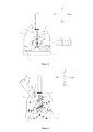
- Permanent magnetic lifting device 1 which has: a housing 2, at the bottom of which is a clamping surface 3 for clamping object 4; a fixed magnet 5, set in housing 2 relatively fixed to housing 2; a turnable magnet 6, set in housing 2 relatively turnable to fixed magnet 5.
- a positioning mechanism 7 for second position.
- the positioning mechanism 7 for second position positions turnable magnet 6 in the second position relative to fixed magnet 5, fixed magnet 5 and turnable magnet 6 generate trial clamping magnetic force to clamping surface 3 for trial clamping of object 4; the trial clamping magnetic force is higher than said zero magnetic force and lower than the maximum magnetic force. It is better to have said trial clamping magnetic force within 10% to 90% of maximum magnetic force.
- said trial clamping magnetic force be 50% of maximum magnetic force, that is, if a workpiece can be lifted up with the trial clamping magnetic force in second position, it can be determined that under the specific condition, the ratio of the maximum clamping force that can be generated by the permanent magnetic lifting device in third position to the weight of workpiece is certain to equal or exceed the ratio set for second position, which is 1/50%, namely 2 times. Similarly, if the trial clamping magnetic force set for second position is 30% of the maximum magnetic force, then the ratio set for second position is 1/30%, namely 3.33 times.
- clamping surface 3 is two bilaterally symmetrical parts of the lower surface of housing 2, in a planar form.
- Fixed magnet 5 and turnable magnet 6 are both cuboids.
- Fixed magnet 5 is fixed to the upper part inside housing 2, and is located in the center in left-right direction of permanent magnetic lifting device 1.
- the fixed magnet 5 is so fixed that it is along its height perpendicular to the plane on which clamping surface 3 lies, the direction of its height agrees with the up-down direction, the direction of its width agrees with the left-right direction, and the direction of its length agrees with the front-rear direction.
- Two sides on the width of fixed magnet 5 are S pole and N pole respectively.
- Two sides on the width of turnable magnet 6 are S pole and N pole respectively.
- Turnable magnet 6 is set in the lower part inside housing 2, and is located in the center in left-right direction of permanent magnetic lifting device 1.
- the turnable magnet 6 is so set that the direction of its length agrees with the front-rear direction, and it is able to turn around its own centerline 62 parallel to its lengthwise direction; the centerline 62 is approximately on the plane on which lies center plane 51 which bisects fixed magnet 5 along the height of fixed magnet 5.
- center plane 61 of turnable magnet 6, which bisects turnable magnet 6 along the height of turnable magnet 6, roughly aligns to center plane 51 of fixed magnet 5 (if the magnetic energy of turnable magnet 6 is greater than the magnetic energy of fixed magnet 5, a relatively small angle can be included between center plane 61 of turnable magnet 6 and center plane 51 of fixed magnet 5, at this time, the magnetic energy of turnable magnet 6, after partial short-circuit, the remaining magnetic energy is neutralized with the magnetic energy of fixed magnet 5), and is roughly on the same plane; turnable magnet 6 is so set that the direction of its width agrees with the left-right direction, and the direction of its height agrees with the up-down direction; and N pole on turnable magnet 6 and S pole on fixed magnet 5 are both on the left side of fixed magnet 5, S pole on turnable magnet 6 and N pole on fixed magnet 5 are both on the right side of fixed magnet 5.
- turnable magnet 6 and fixed magnet 5 can be the opposite of above description.
- the direction of magnetic field generated by fixed magnet 5 is exactly opposite the direction of magnetic field generated by turnable magnet 6, as shown with the lines of magnetic force in Figure 4 .
- Two magnetic fields are neutralized, the magnetic force generated to clamping surface 3 is zero, and object 4 cannot be clamped.
- center plane 61 of turnable magnet 6 makes a predetermined included angle with center plane 51 of fixed magnet 5.
- one part of fixed magnet 5 is shorted through the iron part of magnetic core 81
- one part of turnable magnet 6 is shorted through the iron part of housing 2; their another parts have the same direction in magnetic fields, and these two magnetic fields are superimposed, generating trial clamping magnetic force to clamping surface 3 for trial clamping of object 4.
- the trial clamping magnetic force is higher than zero magnetic force and lower than maximum magnetic force. For trial clamping of object 4, it is better to have trial clamping magnetic force within 10% to 90% of maximum magnetic force, and it is the best to have trial clamping magnetic force be 50% of maximum magnetic force.
- center plane 61 of turnable magnet 6 roughly aligns to center plane 51 of fixed magnet 5, and is roughly on the same plane.
- Turnable magnet 6 is so set that the direction of its width agrees with the left-right direction, and the direction of its height agrees with the up-down direction; and S pole on turnable magnet 6 and S pole on fixed magnet 5 are both on left side of fixed magnet 5, N pole on turnable magnet 6 and N pole on fixed magnet 5 are both on the right side of fixed magnet 5.
- magnetic field generated by fixed magnet 5 and magnetic field generated by turnable magnet 6 have the same direction, as shown with the lines of magnetic force in Figure 6 . These two magnetic fields are superimposed, the magnetic force generated to clamping surface 3 is the maximum magnetic force, thus clamping object 4.
- the permanent magnetic lifting device 1 also has a handle 8, the handle 8 is for an operator to operate manually outside housing 2 to drive turnable magnet 6 to the first position, second position or third position.
- the handle 8 has: a magnetic core 81; inside a part of magnetic core 81 is set internally turnable magnet 6; this part is inserted into a hole 21 made internally in housing 2; another part of magnetic core 81 protrudes out of housing 2; on this another part a through hole 83 is made radially; a handle grip 82; one end of the handle grip 82 is for an operator to operate manually outside housing 2, another end is inserted into and through the through hole 83. An operator holds handle grip 82 to turn the handle, thus driving magnetic core 81 to turn, and finally turnable magnet 6 turns with magnetic core 81.
- Positioning mechanism 7 for second position includes: a retaining pin 71, which is set in the part of housing 2, corresponding to the travel route of the handle, in the course of handle 8 driving turnable magnet 6 to turn from the first position to the third position; a spring 72, applying elastic thrust to retaining pin 71 so that retaining pin 71 protrudes out of housing 2 in normal state; and an actuator 73, exposed outside housing 2 for an operator to operate so that retaining pin 71 overcomes the elastic thrust of spring 72 and retracts into housing 2.
- a deep hole 22 is made in front-rear direction
- spring 72 is set in deep hole 22
- rear end of spring 72 touches the bottom of deep hole 22.
- Rear end of retaining pin 71 touches front end of spring 72
- the middle part of retaining pin 71 integrates with actuator 73
- slope 74 is the inclined plane formed by means of cutting the front end of retaining pin 71 intersecting the axis of retaining pin 71, that is, slope 74 is a slope which inclines from right to left with inclination from rear to front.
- Positioning mechanism 9 for first position and third position is installed on the front surface of housing 2 with screws, and is located just beneath magnetic core 81 of handle 8 and adjoining magnetic core 81.
- positioning mechanism 9 for first position and third position may also integrate with housing 2.
- the positioning mechanism 9 for first position and third position is roughly in the shape of a concave.
- turnable magnet 6 is in the first position or third position
- another end of handle grip 82 protrudes right above the step on either left side or right side of positioning mechanism 9 for first position and third position under the thrust of spring 91
- turning of handle grip 82 is stopped by the steps on both left and right sides of positioning mechanism 9 for first position and third position, so that turnable magnet 6 is positioned in the first position and the third position.
- an operator wants to turn handle 8 he/she must overcome the thrust of spring 91 and pull another end of handle grip 82 to force it away from above the step on either left side or right side to turn handle 8.
- handle 8 When handle 8 turns to the position where retaining pin 71 is set, under the condition that actuator 73 is not operated, handle 8 touches slope 74 and pushes slope 74 so that retaining pin 71 overcomes the elastic thrust of spring 72 and retracts into housing 2, handle 8 is thus able to pass the position where retaining pin 71 is set.
- handle 8 turns automatically to the position where retaining pin 71 is set, under the condition that actuator 73 is not operated, handle 8 touches plane 75, which is on the back of slope 74, of retaining pin 71 and is blocked by retaining pin 71, thus being positioned where retaining pin 71 is set, that is, turnable magnet 6 is positioned in the second position.
- Fixed magnets 251, 252 and turnable magnet 6 are all cuboids.
- a pair of fixed magnets 251 and 252 connect to insulator 253 on both sides of its width and integrate with it, and are fixed to the upper part inside housing 2.
- Insulator 253 is so set that the direction of its width agrees with the left-right direction, the direction of its length agrees with the front-rear direction, and the direction of its height agrees with the up-down direction.
- the planes formed on insulator 253 lengthwise and widthwise are parallel to the plane on which clamping surface 3 lies; S poles and N poles on fixed magnets 251 and 252 are on the side opposite the plane on which clamping surface 3 lies and the side on the back of this side respectively, and fixed magnets 251 and 252 have opposite polarities, that is, S pole on fixed magnet 251 and N pole on fixed magnet 252 are on the side opposite the plane on which clamping surface 3 lies, N pole on fixed magnet 251 and S pole on fixed magnet 252 are on the side on the back of this side.
- Turnable magnet 6 is set on the lower part inside housing 2, and is located in the center in left-right direction of permanent magnetic lifting device 1. Two sides on the width of turnable magnet 6 are S pole and N pole respectively.
- Turnable magnet 6 is able to turn around its own centerline 62 parallel to its lengthwise direction; centerline 62 is approximately on the plane on which lies center plane 254 which bisects insulator 253 along the height of insulator 253.
- center plane 61 of turnable magnet 6, which bisects turnable magnet 6 along its height roughly aligns to center plane 254 of insulator 253 (if the magnetic energy of turnable magnet 6 is greater than the total magnetic energy of fixed magnets 251 and 252, a relatively small angle can be included between center plane 61 of turnable magnet 6 and center plane 254 of insulator 253, at this time, the magnetic energy in turnable magnet 6, after partial short-circuit, the remaining magnetic energy is neutralized with the magnetic energy in fixed magnets 251 and 252), and is roughly on the same plane.
- Turnable magnet 6 is so set that the direction of its width agrees with the left-right direction, and the direction of its height agrees with the up-down direction.
- Fixed magnet 251 is on the N pole side of turnable magnet 6, and the side on fixed magnet 251 near turnable magnet 6, namely the lower side, is S pole.
- Fixed magnet 252 is on the S pole side of turnable magnet 6, and the side on fixed magnet 252 near turnable magnet 6, namely the lower side, is N pole.
- polarities on turnable magnet 6 and fixed magnets 251 and 252 can be the opposite to above description.
- the direction of magnetic fields generated by fixed magnets 251 and 252 is exactly opposite the direction of magnetic field generated by turnable magnet 6, as shown with the lines of magnetic force in Figure 9 .
- the magnetic fields are neutralized, the magnetic force generated to clamping surface 3 is zero, and object 4 cannot be clamped.
- center plane 61 of turnable magnet 6 makes a predetermined included angle with center plane 254 of insulator 253.
- a part of the magnetic fields of fixed magnets 251, 252 and turnable magnet 6 are shorted with housing through the magnetic core inside permanent magnetic lifting device 1, and another part of the magnetic fields have the same direction, and these magnetic fields are superimposed, generating trial clamping magnetic force to clamping surface 3 for trial clamping of object 4.
- the trial clamping magnetic force is higher than zero magnetic force and lower than maximum magnetic force. For trial clamping of object 4, it is better to have trial clamping magnetic force within 10% to 90% of maximum magnetic force, and it is the best to have trial clamping magnetic force be 50% of maximum magnetic force.
- center plane 61 of turnable magnet 6 roughly aligns to center plane 254 of insulator 253, and is roughly on the same plane.
- Turnable magnet 6 is so set that the direction of its width agrees with the left-right direction, and the direction of its height agrees with the up-down direction.
- Fixed magnet 251 is on the S pole side of turnable magnet 6, and the side on fixed magnet 251 near turnable magnet 6, namely the lower side, is S pole.
- Fixed magnet 252 is on the N pole side of turnable magnet 6, and the side on fixed magnet 252 near turnable magnet 6, namely the lower side, is N pole.
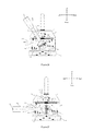
- the difference in structures between the third embodiment and the first embodiment is in the structure of handle, positioning mechanism for second position, and positioning mechanism for first position and third position.
- the positioning mechanism for second position is retaining pin 307.
- the retaining pin 307 is set fixedly in the part on housing 2, corresponding to the travel route of handle 8, in the course of handle 8 driving turnable magnet 6 to turn from the first position to the third position, protruding out of housing 2.
- Handle 8 includes: a stopper 383, which protrudes from the outer circumferential surface of handle 8 to the side of housing; a pressing piece 384, which connects stopper 383 with a rod-like part 386 and protrudes out of handle 8 for a certain distance for an operator to depress to move stopper 383; a spring 385, which applies elastic thrust to pressing piece 384 so that that pressing piece 384 keeps protruding out of handle 8 for a certain distance in normal state.
- a deep hole 387 is made along its length.
- a portion, which is near magnetic core 81 (called internal portion hereinafter), and another portion, which is far away from magnetic core 81 (called external portion hereinafter), have larger internal diameters, while the middle portion of the hole has a smaller internal diameter.
- Stopper 383 is set in the position in deep hole 387, most close to the middle portion of the hole, and, through the rod-like part 386 inserted in the above-mentioned middle portion, connects pressing piece 384 set in the external portion of deep hole 387. A part of pressing piece 384 protrudes out of handle 8 for a certain distance.
- One end of spring 385 props the step between the middle portion and external portion of deep hole 387, and another end props pressing piece 384, to exert elastic thrust to pressing piece 384, so that pressing piece 384 keeps protruding out of handle 8 for a certain distance in normal state.
- a groove is made along the length of grip 382. The groove is positioned corresponding to the position of internal portion of deep hole 387, and connects to the internal portion of deep hole 387. Stopper 383 protrudes from the bottom of the groove out of grip 382.
- Positioning mechanism for first position and third position includes positioning pins 391, 392, and a retaining pin 393, among which, positioning pins 391 and 392 are set fixedly in the lower parts on the left and right sides respectively of the front surface of housing 2; retaining pin 393 is set fixedly in the middle on the left side of the front surface of housing 2.
- turnable magnet 6 When turnable magnet 6 is in the third position, under the condition that pressing piece 384 is not depressed, stopper 383 on handle 6 is located above positioning pin 391 and below retaining pin 393, and touches positioning pin 391 and retaining pin 393, turnable magnet 6 is thus positioned in the third position.
- handle 8 turns automatically to the position where retaining pin 307 is set, under the condition that pressing piece 384 is not depressed, handle 8 touches retaining pin 307 and is blocked by retaining pin 307, thus being positioned where retaining pin 307 is set, that is, turnable magnet 6 is positioned in the second position.
- stopper 383 touches positioning pin 391 and retaining pin 393, handle 8 is thus positioned, that is, turnable magnet 6 is positioned in the third position.
- the magnetic fields of fixed magnet 5 and turnable magnet 6 are superimposed, the magnetic force generated to clamping surface 3 is the maximum magnetic force, thus clamping object 4.
- the operator carries out hoisting of object 4 in the third position.
- Fixed magnets 451, 452 and turnable magnet 6 are all cuboids.
- a pair of fixed magnets 451 and 452 connect to insulator 453 on both sides of its width and integrate with it, and are fixed to the upper part inside housing 2. Insulator 453 is so set that the direction of its width agrees with the left-right direction, the direction of its length agrees with the front-rear direction, and the direction of its height agrees with the up-down direction.
- the planes formed on insulator 453 lengthwise and widthwise are parallel to the plane on which clamping surface 3 lies; S poles and N poles on fixed magnets 451 and 452 are on the side opposite the plane on which clamping surface 3 lies and the side on the back of this side respectively, and fixed magnets 451 and 452 have opposite polarities, that is, S pole on fixed magnet 451 and N pole on fixed magnet 452 are on the side opposite the plane on which clamping surface 3 lies, N pole on fixed magnet 451 and S pole on fixed magnet 452 are on the side on the back of this side.
- Turnable magnet 6 is set on the lower part inside housing 2, and is located in the center in left-right direction of permanent magnetic lifting device 1. Two sides on the width of turnable magnet 6 are S pole and N pole respectively.
- Turnable magnet 6 is able to turn around its own centerline 62 parallel to its lengthwise direction; centerline 62 is approximately on the plane on which lies center plane 454 which bisects insulator 453 along the height of insulator 453.
- center plane 61 of turnable magnet 6, which bisects turnable magnet 6 along its height roughly aligns to center plane 454 of insulator 453 (if the magnetic energy of turnable magnet 6 is greater than the total magnetic energy of fixed magnets 451 and 452, a relatively small angle can be included between center plane 61 of turnable magnet 6 and center plane 454 of insulator 453, at this time, the magnetic energy in turnable magnet 6, after partial short-circuit, the remaining magnetic energy is neutralized with the magnetic energy in fixed magnets 451 and 452), and is roughly on the same plane.
- Turnable magnet 6 is so set that the direction of its width agrees with the left-right direction, and the direction of its height agrees with the up-down direction.
- Fixed magnet 451 is on the N pole side of turnable magnet 6, and the side on fixed magnet 451 near turnable magnet 6, namely the lower side, is S pole.
- Fixed magnet 452 is on the S pole side of turnable magnet 6, and the side on fixed magnet 452 near turnable magnet 6, namely the lower side, is N pole.
- the direction of magnetic fields generated by fixed magnets 451 and 452 is exactly opposite the direction of magnetic field generated by turnable magnet 6, as shown with the lines of magnetic force in Figure 17 .
- the magnetic fields are neutralized, the magnetic force generated to clamping surface 3 is zero, and object 4 cannot be clamped.
- center plane 61 of turnable magnet 6 makes a predetermined included angle with center plane 454 of insulator 453.
- a part of the magnetic fields of fixed magnets 451, 452 and turnable magnet 6 are shorted with housing through the magnetic core inside permanent magnetic lifting device 1, and another part of the magnetic fields have the same direction, and these magnetic fields are superimposed, generating trial clamping magnetic force to clamping surface 3 for trial clamping of object 4.
- the trial clamping magnetic force is higher than zero magnetic force and lower than maximum magnetic force. For trial clamping of object 4, it is better to have trial clamping magnetic force within 10% to 90% of maximum magnetic force, and it is the best to have trial clamping magnetic force be 50% of maximum magnetic force.
- center plane 61 of turnable magnet 6 roughly aligns to center plane 454 of insulator 453, and is roughly on the same plane.
- Turnable magnet 6 is so set that the direction of its width agrees with the left-right direction, and the direction of its height agrees with the up-down direction.
- Fixed magnet 451 is on the S pole side of turnable magnet 6, and the side on fixed magnet 451 near turnable magnet 6, namely the lower side, is S pole.
- Fixed magnet 452 is on the N pole side of turnable magnet 6, and the side on fixed magnet 452 near turnable magnet 6, namely the lower side, is N pole.
- the difference in structures between the fifth embodiment and the first embodiment is in the structure of the positioning mechanism for first position and third position.
- the positioning mechanism for first position and third position includes a retaining mechanism 570 and positioning pins 591 and 592.
- Retaining mechanism 570 has the same structure as positioning mechanism 7 for second position. It includes: a retaining pin 571, set in the part of housing 2, corresponding to the travel route of the handle, in the course of handle 8 driving turnable magnet 6 to turn from the second position to the third position, i.e. set in the center of the left side of the front surface of housing 2; a spring, applying elastic thrust to retaining pin 571 so that retaining pin 571 protrudes out of housing 2 in normal state; and an actuator 573, exposed outside housing 2 for an operator to operate so that retaining pin 571 overcomes the elastic thrust of spring and retracts into housing 2.
- a deep hole 22 is made in front-rear direction, a spring is set in deep hole 22, rear end of the spring touches the bottom of deep hole 22.
- Rear end of retaining pin 571 touches front end of the spring
- the middle part of retaining pin 571 integrates with actuator 573
- slope 574 is the inclined plane formed by means of cutting the front end of retaining pin 571 intersecting the axis of retaining pin 571, that is, slope 574 is a slope which inclines from top to bottom with inclination from rear to front.
- Positioning pins 591 and 592 are set fixedly on the lower parts of the left and right sides respectively of the front surface of housing 2.
- grip 82 on handle 8 is located above positioning pin 592 and touches positioning pin 592, turnable magnet 6 is thus positioned in the first position.
- grip 82 is located above positioning pin 591 and below retaining pin 571, and touches positioning pin 591 and retaining pin 571, turnable magnet 6 is thus positioned in the third position.
- handle 8 When handle 8 turns to the position where retaining pin 71 is set, under the condition that actuator 73 is not operated, handle 8 touches slope 74 and pushes slope 74 so that retaining pin 71 overcomes the elastic thrust of spring 72 and retracts into housing 2, handle 8 is thus able to pass the position where retaining pin 71 is set.
- handle 8 turns automatically to the position where retaining pin 71 is set, under the condition that actuator 73 is not operated, handle 8 touches plane 75, which is on the back of slope 74, of retaining pin 71 and is blocked by retaining pin 71, thus being positioned where retaining pin 71 is set, that is, turnable magnet 6 is positioned in the second position.
- Grip 82 on handle 8 is located above positioning pin 591 and below retaining pin 571.
- Handle 8 touches positioning pin 591, and under the condition that actuator is not operated, handle 8 also touches plane 575, which is on the back of slope 574, on retaining pin 571, handle 8 is thus positioned, that is, turnable magnet 6 is positioned in the third position.
- the magnetic fields of fixed magnet 5 and turnable magnet 6 are superimposed, the magnetic force generated to clamping surface 3 is the maximum magnetic force, thus clamping object 4.
- the operator carries out hoisting of object 4 in the third position.
- the operator When object 4 is hoisted and moved to a prescribed location, the operator, after unloading the workpiece, first operates actuator 573 to retract retaining pin 571 into housing 2, and at the same time, to turn handle 8 clockwise to pass the position where retaining pin 571 is set, and turn to the position for retaining pin 71, then operates actuator 73 to retract retaining pin 71 into housing 2, thus to enable handle 8 to pass the position for retaining pin 71 and turn further to the "OFF" position.
- Fixed magnets 651, 652 and turnable magnet 6 are all cuboids.
- a pair of fixed magnets 651 and 652 connect to insulator 653 on both sides of its width and integrate with it, and are fixed to the upper part inside housing 2.
- Insulator 653 is so set that the direction of its width agrees with the left-right direction, the direction of its length agrees with the front-rear direction, and the direction of its height agrees with the up-down direction.
- the planes formed on insulator 653 lengthwise and widthwise are parallel to the plane on which clamping surface 3 lies; S poles and N poles on fixed magnets 651 and 652 are on the side opposite the plane on which clamping surface 3 lies and the side on the back of this side respectively, and fixed magnets 651 and 652 have opposite polarities, that is, S pole on fixed magnet 651 and N pole on fixed magnet 652 are on the side opposite the plane on which clamping surface 3 lies, N pole on fixed magnet 651 and S pole on fixed magnet 652 are on the side on the back of this side.
- Turnable magnet 6 is set on the lower part inside housing 2, and is located in the center in left-right direction of permanent magnetic lifting device 1. Two sides on the width of turnable magnet 6 are S pole and N pole respectively. Turnable magnet 6 is able to turn around its own centerline 62 parallel to its lengthwise direction; centerline 62 is approximately on the plane on which lies center plane 654 which bisects insulator 653 along the height of insulator 653.
- center plane 61 of turnable magnet 6, which bisects turnable magnet 6 along its height, roughly aligns to center plane 654 of insulator 653 (if the magnetic energy of turnable magnet 6 is greater than the total magnetic energy of fixed magnets 651 and 652, a relatively small angle can be included between center plane 61 of turnable magnet 6 and center plane 654 of insulator 653, at this time, the magnetic energy in turnable magnet 6, after partial short-circuit, the remaining magnetic energy is neutralized with the magnetic energy in fixed magnets 651 and 652), and is roughly on the same plane.
- Turnable magnet 6 is so set that the direction of its width agrees with the left-right direction, and the direction of its height agrees with the up-down direction.
- Fixed magnet 651 is on the N pole side of turnable magnet 6, and the side on fixed magnet 651 near turnable magnet 6, namely the lower side, is S pole.
- Fixed magnet 652 is on the S pole side of said turnable magnet 6, and the side on fixed magnet 652 near turnable magnet 6, namely the lower side, is N pole.
- the direction of magnetic fields generated by fixed magnets 651 and 652 is exactly opposite the direction of magnetic field generated by turnable magnet 6, as shown with the lines of magnetic force in Figure 25 .
- the magnetic fields are neutralized, the magnetic force generated to clamping surface 3 is zero, and object 4 cannot be clamped.
- center plane 61 of turnable magnet 6 makes a predetermined included angle with center plane 654 of insulator 653.
- a part of the magnetic fields of fixed magnets 651, 652 and turnable magnet 6 are shorted with housing through the magnetic core inside permanent magnetic lifting device 1, and another part of the magnetic fields have the same direction, and these magnetic fields are superimposed, generating trial clamping magnetic force to clamping surface 3 for trial clamping of object 4.
- the trial clamping magnetic force is higher than zero magnetic force and lower than maximum magnetic force. For trial clamping of object 4, it is better to have trial clamping magnetic force within 10% to 90% of maximum magnetic force, and it is the best to have trial clamping magnetic force be 50% of maximum magnetic force.
- center plane 61 of turnable magnet 6 roughly aligns to center plane 654 of insulator 653, and is roughly on the same plane.
- Turnable magnet 6 is so set that the direction of its width agrees with left-right direction, and the direction of its height agrees with up-down direction.
- Fixed magnet 651 is on the S pole side of turnable magnet 6, and the side on fixed magnet 651 near turnable magnet 6, namely the lower side, is S pole.
- Fixed magnet 652 is on the N pole side of turnable magnet 6, and the side on fixed magnet 652 near turnable magnet 6, namely the lower side, is N pole.
- turnable magnet is positioned in the second position by means of the positioning mechanism for second position, so that trial clamping magnetic force is higher than zero magnetic force and lower than maximum magnetic force, thus enabling an operator to easily operate trial clamping, and through operation of trial clamping, potential risk in safety which may occur in hoisting in the third position can also be thoroughly eliminated.
- fixed magnet is positioned above turnable magnet. But this invention is not limited to this arrangement. Fixed magnet can also be positioned below turnable magnet.
- fixed magnet is fixed in housing vertically or horizontally. But this invention is not limited to this arrangement.
- fixed magnets 751 and 752 may also be fixed in housing aslant in a splay way.
- fixed magnets 751, 752 and turnable magnet 6 are all cuboids; a pair of fixed magnets 751 and 752 slant in a splay way symmetrically about the center plane perpendicular to clamping surface 3; the left and right sides opposite each other on a pair of fixed magnets 751 and 752 are S pole and N pole respectively, and the left and right sides away from each other are N pole and S pole respectively; two sides on the width of turnable magnet 6 are S pole and N pole respectively; turnable magnet 6 is able to turn around its own centerline 62 parallel to its lengthwise direction.
- center plane 61 of turnable magnet 6, which bisects turnable magnet 6 along its height, roughly aligns to the center plane perpendicular to clamping surface 3, and is roughly on the same plane;
- the left side in two opposite sides of a pair of fixed magnets 751 and 752 is S pole, one side of turnable magnet 6 opposite the left side is N pole;
- the right side in two opposite sides of a pair of fixed magnets 751 and 752 is N pole, another side of turnable magnet 6 is S pole (Of course, polarities on turnable magnet 6 and fixed magnets 751 and 752 can be the opposite to above description).
- center plane 61 of turnable magnet 6, which bisects turnable magnet 6 along its height, makes a predetermined included angle with the center plane perpendicular to clamping surface 3.
- the left side in two opposite sides of a pair of fixed magnets 751 and 752 is S pole
- one side of turnable magnet 6 opposite this side is S pole
- the right side in two opposite sides of a pair of fixed magnets 751 and 752 is N pole
- another side of turnable magnet 6 is N pole.
Claims (8)
- Permanentmagnet-Hebevorrichtung (1), die aufweist: ein Gehäuse (2), wobei an dem Boden des Gehäuses eine Klemmfläche (3) angeordnet ist, um Objekte (4) zu klemmen; einen festgelegten Magneten (5), der im Gehäuse (2) angeordnet und relativ zum Gehäuse (2) festgelegt ist; einen drehbaren Magneten (6), der im Gehäuse (2) angeordnet und relativ zum festgelegten Magneten (5) drehbar ist; wobei die Magnetkraft, die durch den festgelegten Magneten (5) und den drehbaren Magneten (6) auf die Klemmfläche (3) erzeugt wird, null ist, wenn sich der drehbare Magnet (6) in der ersten Position relativ zum festgelegten Magneten (5) befindet; und wobei die Magnetkraft, die durch den festgelegten Magneten (5) und den drehbaren Magneten (6) auf die Klemmfläche (3) erzeugt wird, die maximale Magnetkraft ist, wenn sich der drehbare Magnet (6) in der dritten Position relativ zum festgelegten Magneten (5) befindet; wobei
die Permanentmagnet-Hebevorrichtung (1) auch einen Positionierungsmechanismus (7) für eine zweite Position aufweist, wobei der Positionierungsmechanismus ausgebildet ist, den drehbaren Magneten (6) in der zweiten Position relativ zum festgelegten Magneten (5) zu positionieren, sodass der festgelegte Magnet (5) und der drehbare Magnet (6) eine Klemmprobe-Magnetkraft auf die Klemmfläche (3) erzeugen, um Objekte (4) auf Probe zu klemmen; wobei die Klemmprobe-Magnetkraft größer als null und niedriger als die maximale Magnetkraft ist;
wobei der festgelegte Magnet (5) und der drehbare Magnet (6) beide Quader sind, wobei der festgelegte Magnet (5) entlang seine Höhe senkrecht zu der Ebene, in der die Klemmfläche (3) liegt, ist, zwei Seiten auf der Breite des festgelegten Magneten (5) jeweils der S-Pol und der N-Pol sind, und zwei Seiten auf der Breite des drehbaren Magneten (6) jeweils der S-Pol und der N-Pol sind, wobei der drehbare Magnet (6) geeignet ist, sich um seine eigene Mittellinie (62), parallel zu seiner Längsrichtung, zu drehen; wobei der N-Pol an dem drehbaren Magneten (6) und der S-Pol an dem festgelegten Magneten (5) auf einer Seite der Breite des festgelegten Magneten (5) angeordnet sind und der S-Pol an dem drehbaren Magneten (6) und der N-Pol an dem festgelegten Magneten (5) auf einer anderen Seite der Breite des festgelegten Magneten (5) angeordnet sind, wenn der drehbare Magnet (6) in die erste Position gedreht wird;
wobei die Mittelebene (61) des drehbaren Magneten (6), die den drehbaren Magneten (6) entlang seiner Höhe halbiert, einen vorbestimmten eingeschlossenen Winkel mit der Mittelebene (51) des festgelegten Magneten (5), die den festgelegten Magneten (5) entlang seiner Höhe halbiert, bildet, wenn der drehbare Magnet (6) in die zweite Position gedreht wird;
wobei der S-Pol an dem drehbaren Magneten (6) und der S-Pol an dem festgelegten Magneten (5) auf einer Seite der Breite des festgelegten Magneten (5) angeordnet sind und der N-Pol an dem drehbaren Magneten (6) und der N-Pol an dem festgelegten Magneten (5) auf einer anderen Seite der Breite des festgelegten Magneten (5) angeordnet sind, wenn der drehbare Magnet (6) in die dritte Position gedreht wird; und
wobei die Permanentmagnet-Hebevorrichtung (1) auch einen Griff (8) aufweist, wobei der Griff (8) einem Bediener zur manuellen Bedienung außerhalb des Gehäuses (2) dient, um den drehbaren Magneten (6) in die erste, die zweite oder die dritte Position anzutreiben;
und
wobei der Positionierungsmechanismus (7) für die zweite Position einen ersten Haltestift (71) enthält, der in dem Teil des Gehäuses (2) angeordnet ist, der der Bewegungsstrecke des Griffs (8) im Verlauf des Griffs (8), der den drehbaren Magneten (6) antreibt, um sich von der ersten Position in die dritte Position zu bewegen, entspricht;
wobei
der Positionierungsmechanismus (7) für die zweite Position eine erste Feder (72) enthält, die elastischen Druck auf den ersten Haltestift (71) ausübt, sodass der erste Haltestift (71) in einem normalen Zustand aus dem Gehäuse (2) vorsteht; und wobei ein Betätigungselement (73), das außerhalb des Gehäuses (2) für einen Bediener freigelegt ist, um zu bedienen, sodass der erste Haltestift (71) den elastischen Druck der ersten Feder (72) überwindet und sich in das Gehäuse (2) zurückzieht; und
eine Steigung (74) am vorderen Ende des ersten Haltestifts (71) angeordnet ist, wobei der Griff (8) im Verlauf des Griffs (8), der den drehbaren Magneten (6) antreibt, um sich von der ersten Position in die dritte Position zu bewegen, wenn sich der Griff (8) in die Position bewegt, in der der erste Haltestift (71) angeordnet ist, unter der Bedingung, dass das Betätigungselement (73) nicht bedient wird, die Steigung (74) berührt und die Steigung (74) drückt, sodass der erste Haltestift (71) den elastischen Druck der ersten Feder (72) überwindet und sich in das Gehäuse (2) zurückzieht, wobei dem Griff (8) ermöglicht wird, die Position, in der der erste Haltestift (71) angeordnet ist, zu passieren; wobei der Griff im Verlauf des Griffs (8), der den drehbaren Magneten (6) antreibt, um sich von der dritten Position in die erste Position zu bewegen, wenn sich der Griff (8) in die Position bewegt, in der der erste Haltestift (71) angeordnet ist, unter der Bedingung, dass das Betätigungselement (73) nicht bedient wird, die Ebene (75) des ersten Haltestifts (71) berührt, die auf der Rückseite der Steigung (74) angeordnet ist, und durch den ersten Haltestift (71) blockiert wird, wodurch er dort positioniert wird, wo der erste Haltestift (71) angeordnet ist; und weiter
das hintere Ende des ersten Haltestifts (71) die erste Feder (72) berührt, wobei der Mittelteil des ersten Haltestifts (71) sich mit dem Betätigungselement (73) integriert, wobei die Steigung (74) die gewinkelte Ebene ist, die mittels Schneidens des vorderen Endes des ersten Haltestifts (71), das die Achse des ersten Haltestifts (71) schneidet, gebildet wird. - Permanentmagnet-Hebevorrichtung (1) wie in Anspruch 1 beansprucht, die dadurch gekennzeichnet ist, dass:der festgelegte Magnet (5; 251, 252; 451, 452; 651, und der drehbare Magnet (6) alle Quader sind; wobei ein Paar von festgelegten Magneten (251, 252; 451, 452; 651, 652) sich auf beiden Seiten an deren Breite mit einem Isolator (253; 453; 653) verbinden und damit integrieren, und die Ebenen, die auf dem Isolator der Länge und der Breite nach gebildet sind, parallel zu der Ebene sind, in der die Klemmfläche (3) liegt; wobei die S-Pole und N-Pole an den festgelegten Magneten (251, 252; 451, 452; 651, 652) auf der Seite, die der Ebene, in der die Klemmfläche (3) liegt und entsprechend der Seite an der Rückseite dieser Seite, gegenüberliegen, und ein Paar von festgelegten Magneten (251, 252; 451, 452; 651, 652) entgegengesetzte Polaritäten aufweisen; wobei zwei Seiten an der Breite des drehbaren Magneten jeweils der S-Pol und der N-Pol sind; wobei der drehbare Magnet (6) geeignet ist, sich um seine eigene Mittellinie (62), parallel zu seiner Längsrichtung, zu drehen;wobei einer von dem Paar der festgelegten Magneten (251, 252; 451, 452; 651, 652) auf der N-Pol-Seite des drehbaren Magneten angeordnet ist und eine Seite des festgelegten Magneten (251, 252; 451, 452; 651, 652), die in der Nähe des drehbaren Magneten (6) liegt, der S-Pol ist, wenn sich der drehbare Magnet (6) in die erste Position dreht; wobei ein anderer von dem Paar der festgelegten Magneten (251, 252; 451, 452; 651, 652) auf der S-Pol-Seite des drehbaren Magneten angeordnet ist und eine Seite des festgelegten Magneten (251, 252; 451, 452; 651, 652), die in der Nähe des drehbaren Magneten (6) liegt, der N-Pol ist;wobei die Mittelebene (61) des drehbaren Magneten (6), die den drehbaren Magneten (6) entlang seiner Höhe halbiert, einen vorbestimmten eingeschlossenen Winkel mit der Mittelebene (254; 454; 654) des Isolators (253; 453; 653), die den Isolator (253; 453; 653) entlang seiner Höhe halbiert, bildet, wenn sich der drehbare Magnet (6) in die zweite Position dreht;wobei einer von dem Paar der festgelegten Magneten (251, 252; 451, 452; 651, 652) auf der S-Pol-Seite des drehbaren Magneten (6) angeordnet ist und die Seite des festgelegten Magneten (251, 252; 451, 452; 651, 652), die in der Nähe des drehbaren Magneten (6) liegt, der S-Pol ist, wenn sich der drehbare Magnet (6) in die dritte Position dreht; wobei ein anderer von dem Paar der festgelegten Magneten (251, 252; 451, 452; 651, 652) auf der N-Pol-Seite des drehbaren Magneten (6) angeordnet ist und die Seite des festgelegten Magneten (251, 252; 451, 452; 651, 652), die in der Nähe des drehbaren Magneten (6) liegt, der N-Pol ist.
- Permanentmagnet-Hebevorrichtung (1) wie in Anspruch 1 beansprucht, die dadurch gekennzeichnet ist, dass:der festgelegte Magnet (5; 751, 752) und der drehbare Magnet (6) alle Quader sind; wobei ein Paar von festgelegten Magneten (751, 752) sich in einer gespreizten Art symmetrisch um die Mittelebene, senkrecht zur Klemmfläche (3), neigen; wobei die sich gegenüberliegenden Seiten an einem Paar von festgelegten Magneten (751, 752) jeweils der S-Pol und der N-Pol sind, und die Seiten, die weg voneinander sind, jeweils der N-Pol und der S-Pol sind; wobei zwei Seiten an der Breite des drehbaren Magneten (6) jeweils der S-Pol und der N-Pol sind; wobei der drehbare Magnet (6) geeignet ist, sich um seine eigene Mittellinie (62), parallel zu seiner Längsrichtung, zu drehen;wobei eine der zwei gegenüberliegenden Seiten eines Paares von festgelegten Magneten (751, 752) der S-Pol ist, eine Seite gegenüber zu dieser Seite des drehbaren Magneten (6) der N-Pol ist, eine andere der zwei gegenüberliegenden Seiten eines Paares von festgelegten Magneten (751, 752) der N-Pol ist, und eine andere Seite des drehbaren Magneten (6) der S-Pol ist, wenn sich der drehbare Magnet (6) in die erste Position dreht;wobei die Mittelebene (61) des drehbaren Magneten (6), die den drehbaren Magneten (6) entlang seiner Höhe halbiert, einen vorbestimmten eingeschlossenen Winkel mit der Mittelebene, die senkrecht zu der Klemmfläche (3) ist, bildet, wenn sich der drehbare Magnet (6) in die zweite Position dreht;wobei eine der zwei gegenüberliegenden Seiten eines Paares von festgelegten Magneten (751, 752) der S-Pol ist, eine Seite gegenüber zu dieser Seite des drehbaren Magneten (6) der S-Pol ist, eine andere der zwei gegenüberliegenden Seiten eines Paares von festgelegten Magneten (751, 752) der N-Pol ist, und eine andere Seite des drehbaren Magneten (6) der N-Pol ist, wenn sich der drehbare Magnet (6) in die dritte Position dreht.
- Permanentmagnet-Hebevorrichtung (1) wie in Anspruch 1 beansprucht, die dadurch gekennzeichnet ist, dass:keine Steigung am vorderen Ende des ersten Haltestifts (71) angeordnet ist, wobei der Griff (8) im Verlauf des Griffs (8), der den drehbaren Magneten (6) antreibt, um sich von der ersten Position in die dritte Position zu bewegen, wenn sich der Griff (8) in die Position bewegt, in der der erste Haltestift (71) angeordnet ist, unter der Bedingung, dass das Betätigungselement (73) nicht bedient wird, das vordere Ende des Haltestifts (71) berührt und die Position, in der der erste Haltestift (71) angeordnet ist, nicht passieren kann; wobei der Griff (8), unter der Bedingung dass das Betätigungselement (73) bedient wird, die Position in der der erste Haltestift (71) angeordnet ist, passieren kann, der erste Haltestift (71) den elastischen Druck der ersten Feder (72) überwindet und sich in das Gehäuse (2) zurückzieht;wobei der Griff (8) im Verlauf des Griffs (8), der den drehbaren Magneten (6) antreibt, um sich von der dritten Position in die erste Position zu bewegen, wenn sich der Griff (8) in die Position bewegt, in der der erste Haltestift (71) angeordnet ist, unter der Bedingung, dass das Betätigungselement (73) nicht bedient wird, das vordere Ende des ersten Haltestifts (71) berührt und durch den ersten Haltestift (71) blockiert wird, wodurch er dort positioniert wird, wo der erste Haltestift (71) angeordnet ist.
- Permanentmagnet-Hebevorrichtung (1) wie in Anspruch 1 beansprucht, die dadurch gekennzeichnet ist, dass:der Positionierungsmechanismus (7) für die zweite Position einen zweiten Haltestift (307) enthält; wobei der zweite Haltestift (307) festgelegt an dem Teil des Gehäuses (2) angeordnet ist, der der Bewegungsstrecke des Griffs (8) im Verlauf des Griffs (8), der den drehbaren Magneten (6) antreibt, um sich von der ersten Position in die dritte Position zu bewegen, entspricht und außerhalb des Gehäuses (2) vorsteht; wobei der Griff (8) enthält: einen Stopper (383), der von der äußeren Umfangsoberfläche des Griffs (8) zu der Seite des Gehäuses (2) vorsteht; ein Drückteil (384), das den Stopper (383) mit einem stabähnlichen Teil (386) verbindet und aus dem Griff (8) für eine gewisse Entfernung vorsteht, um von einem Bediener heruntergedrückt zu werden, um den Stopper (383) zu bewegen; eine zweite Feder (385), die elastischen Druck auf das Drückteil (384) ausübt, sodass das Drückteil (384) für eine gewisse Entfernung im normalen Zustand aus dem Griff vorstehen bleibt.
- Permanentmagnet-Hebevorrichtung (1) wie in Anspruch 5 beansprucht, die dadurch gekennzeichnet ist, dass:im Verlauf des Griffs (8), der den drehbaren Magneten (6) antreibt, um sich von der ersten Position in die dritte Position zu bewegen oder von der dritten Position in die erste Position zu bewegen, wenn sich der Griff (8) in die Position bewegt, in der der zweite Haltestift (307) angeordnet ist, unter der Bedingung, dass das Drückteil (384) nicht durch einen Bediener heruntergedrückt wird, der Stopper (383) an dem Griff (8) den zweiten Haltestift (307) berührt, sodass der Griff (8) von dem zweiten Haltestift (307) blockiert wird; wobei sich der Stopper (383) unter der Bedingung, dass das Drückteil (384) durch einen Bediener heruntergedrückt wird, bewegt, um zu verhindem, den zweiten Haltestift (307) zu berühren und dem Griff (8) zu ermöglichen, die Position zu passieren, in der der zweite Haltestift (307) angeordnet ist.
- Permanentmagnet-Hebevorrichtung (1) wie in Anspruch 1 beansprucht, die dadurch gekennzeichnet ist, dass:die Klemmprobe-Magnetkraft zwischen 10% bis 90% der maximalen Magnetkraft liegt.
- Permanentmagnet-Hebevorrichtung (1) wie in Anspruch 1 beansprucht, die dadurch gekennzeichnet ist, dass:die Klemmprobe-Magnetkraft 50% der maximalen Magnetkraft beträgt.
Applications Claiming Priority (1)
| Application Number | Priority Date | Filing Date | Title |
|---|---|---|---|
| PCT/CN2010/000199 WO2011097761A1 (zh) | 2010-02-12 | 2010-02-12 | 永磁起重装置 |
Publications (3)
| Publication Number | Publication Date |
|---|---|
| EP2535307A1 EP2535307A1 (de) | 2012-12-19 |
| EP2535307A4 EP2535307A4 (de) | 2013-07-31 |
| EP2535307B1 true EP2535307B1 (de) | 2015-04-08 |
Family
ID=44367119
Family Applications (1)
| Application Number | Title | Priority Date | Filing Date |
|---|---|---|---|
| EP10845435.6A Active EP2535307B1 (de) | 2010-02-12 | 2010-02-12 | Permanentmagnethebevorrichtung |
Country Status (6)
| Country | Link |
|---|---|
| US (1) | US8757689B2 (de) |
| EP (1) | EP2535307B1 (de) |
| JP (1) | JP2013519601A (de) |
| KR (1) | KR20120109529A (de) |
| CN (1) | CN102574668B (de) |
| WO (1) | WO2011097761A1 (de) |
Cited By (4)
| Publication number | Priority date | Publication date | Assignee | Title |
|---|---|---|---|---|
| WO2019165228A1 (en) * | 2018-02-23 | 2019-08-29 | Magswitch Technology Worldwide Pty Ltd. | Variable field magnetic couplers and methods for engaging a ferromagnetic workpiece |
| US10903030B2 (en) | 2017-04-27 | 2021-01-26 | Magswitch Technology Worldwide Pty Ltd. | Variable field magnetic couplers and methods for engaging a ferromagnetic workpiece |
| US11031166B2 (en) | 2017-06-08 | 2021-06-08 | Magswitch Technology Worldwide Pty Ltd | Electromagnet-switchable permanent magnet device |
| US11097401B2 (en) | 2017-04-27 | 2021-08-24 | Magswitch Technology Worldwide Pty Ltd. | Magnetic coupling device with at least one of a sensor arrangement and a degauss capability |
Families Citing this family (13)
| Publication number | Priority date | Publication date | Assignee | Title |
|---|---|---|---|---|
| JP5617883B2 (ja) * | 2012-09-06 | 2014-11-05 | カネテック株式会社 | 磁気吸着装置 |
| CZ24632U1 (cs) * | 2012-09-10 | 2012-11-29 | Zvedací magnetické zarízení | |
| CN103466425B (zh) * | 2013-07-06 | 2016-06-15 | 李和良 | 磁力加强型永磁起重器 |
| KR101358045B1 (ko) * | 2013-08-14 | 2014-02-04 | 정진권 | 자석 접착식 철판 이송 장치 |
| US10807492B1 (en) * | 2016-04-15 | 2020-10-20 | X Development Llc | Switchable magnetic battery docking |
| US9774221B1 (en) | 2016-04-15 | 2017-09-26 | X Development Llc | Magnetic end effector |
| CN106403747B (zh) * | 2016-08-19 | 2018-11-16 | 赣州轩义科技有限公司 | 一种新型磁力表座 |
| US10308571B2 (en) * | 2017-10-11 | 2019-06-04 | Uop Llc | Process for minimizing benzene, toluene, and a recycle loop in a zero benzene aromatics complex |
| CN108341326A (zh) * | 2018-04-16 | 2018-07-31 | 无锡石油化工起重机有限公司 | 内置加固耐磨型支撑脚的磁力吊 |
| CN108708403A (zh) * | 2018-06-22 | 2018-10-26 | 宜兴市锦丰市政电力设施有限公司 | 一种用于打开井盖的强磁装置 |
| CN108708405A (zh) * | 2018-06-22 | 2018-10-26 | 宜兴市锦丰市政电力设施有限公司 | 一种铁磁性井盖和用于打开井盖的强磁装置 |
| CN110539246A (zh) * | 2019-07-31 | 2019-12-06 | 共享铸钢有限公司 | 一种铲磨设备支撑装置 |
| CN114229245B (zh) * | 2021-12-30 | 2023-05-12 | 中科微影(浙江)医疗科技有限公司 | 一种用于磁共振设备运输的减震系统 |
Family Cites Families (23)
| Publication number | Priority date | Publication date | Assignee | Title |
|---|---|---|---|---|
| JPS4734963U (de) * | 1971-05-14 | 1972-12-19 | ||
| IT7823323V0 (it) * | 1978-11-17 | 1978-11-17 | Cardone Tecnomagnetica | Sollevatore magnetico a comando manuale. |
| FR2523940A1 (fr) * | 1982-03-25 | 1983-09-30 | Braillon Cie | Appareil magnetique, notamment pour la manutention |
| JP2759371B2 (ja) * | 1990-03-23 | 1998-05-28 | コニカ株式会社 | 磁気吸着装置 |
| CN2076088U (zh) * | 1990-10-25 | 1991-05-01 | 无锡县船舶机械戌件厂 | 永磁起重器 |
| FR2675299B1 (fr) * | 1991-04-10 | 1994-09-16 | Braillon Cie | Porteur magnetique a aimants permanents. |
| JPH0647281U (ja) * | 1992-12-04 | 1994-06-28 | 三菱マテリアル株式会社 | 切断用鋸刃の吊り治具 |
| KR950006689Y1 (ko) * | 1992-12-15 | 1995-08-18 | 정형 | 자력 흡착기 |
| CN2161590Y (zh) * | 1993-06-12 | 1994-04-13 | 陈钧台 | 永磁起重器 |
| FR2706881B1 (de) * | 1993-06-24 | 1995-07-28 | Braillon Magnetique Sa | |
| JPH0734963U (ja) * | 1993-12-14 | 1995-06-27 | セーラー万年筆株式会社 | 塗布具 |
| JPH0912259A (ja) * | 1995-06-26 | 1997-01-14 | Hitachi Kizai Kk | 吊上装置 |
| JP3218453B2 (ja) * | 1996-02-09 | 2001-10-15 | 日立機材株式会社 | 吊上装置 |
| IT1301710B1 (it) * | 1998-06-15 | 2000-07-07 | Tecnomagnete Spa | Ancoratore magnetico a comando manuale. |
| GB2358962B (en) * | 2000-02-04 | 2004-04-28 | Eclipse Magnetics Ltd | Method of using magnetic lifting devices |
| US6331810B1 (en) * | 2000-09-01 | 2001-12-18 | Hyung Jung | Magnetic lifting apparatus |
| JP4394905B2 (ja) * | 2003-06-24 | 2010-01-06 | カネテック株式会社 | 磁気吸着装置及びその製造方法並びに磁気装置 |
| JP2006111248A (ja) * | 2004-09-15 | 2006-04-27 | Tsuda Industries Co Ltd | 自動変速機用シフトレバー装置 |
| ES2273551B1 (es) * | 2005-01-19 | 2008-04-01 | Felemamg, S.L. | Disposicion de seguridad para elevadores de iman permanente. |
| CN2773034Y (zh) * | 2005-03-09 | 2006-04-19 | 上海布里斯克机械有限公司 | 整体式永磁起重器 |
| CN2926167Y (zh) * | 2006-01-06 | 2007-07-25 | 宫素霞 | 一种可调节磁吸力的永磁机构 |
| KR100602514B1 (ko) * | 2006-04-10 | 2006-07-19 | 주식회사 우성마그네트 | 리프팅 마그네트 |
| US7548147B2 (en) * | 2007-03-26 | 2009-06-16 | Guang Dar Magnet Industrial Ltd. | Switch type on/off structure for hoisting magnetic disks |
-
2010
- 2010-02-12 EP EP10845435.6A patent/EP2535307B1/de active Active
- 2010-02-12 WO PCT/CN2010/000199 patent/WO2011097761A1/zh active Application Filing
- 2010-02-12 CN CN201080047764.6A patent/CN102574668B/zh not_active Expired - Fee Related
- 2010-02-12 KR KR1020127016737A patent/KR20120109529A/ko not_active Application Discontinuation
- 2010-02-12 US US13/521,503 patent/US8757689B2/en active Active
- 2010-02-12 JP JP2012552220A patent/JP2013519601A/ja active Pending
Cited By (11)
| Publication number | Priority date | Publication date | Assignee | Title |
|---|---|---|---|---|
| US10903030B2 (en) | 2017-04-27 | 2021-01-26 | Magswitch Technology Worldwide Pty Ltd. | Variable field magnetic couplers and methods for engaging a ferromagnetic workpiece |
| US11097401B2 (en) | 2017-04-27 | 2021-08-24 | Magswitch Technology Worldwide Pty Ltd. | Magnetic coupling device with at least one of a sensor arrangement and a degauss capability |
| US11511396B2 (en) | 2017-04-27 | 2022-11-29 | Magswitch Technology Worldwide Pty Ltd. | Magnetic coupling devices |
| US11839954B2 (en) | 2017-04-27 | 2023-12-12 | Magswitch Technology, Inc. | Magnetic coupling device with at least one of a sensor arrangement and a degauss capability |
| US11850708B2 (en) | 2017-04-27 | 2023-12-26 | Magswitch Technology, Inc. | Magnetic coupling device with at least one of a sensor arrangement and a degauss capability |
| US11901141B2 (en) | 2017-04-27 | 2024-02-13 | Magswitch Technology, Inc. | Variable field magnetic couplers and methods for engaging a ferromagnetic workpiece |
| US11901142B2 (en) | 2017-04-27 | 2024-02-13 | Magswitch Technology, Inc. | Variable field magnetic couplers and methods for engaging a ferromagnetic workpiece |
| US11031166B2 (en) | 2017-06-08 | 2021-06-08 | Magswitch Technology Worldwide Pty Ltd | Electromagnet-switchable permanent magnet device |
| US11651883B2 (en) | 2017-06-08 | 2023-05-16 | Magswitch Technology Worldwide Pty Ltd. | Electromagnet-switchable permanent magnet device |
| US11837402B2 (en) | 2017-06-08 | 2023-12-05 | Magswitch Technology, Inc. | Electromagnet-switchable permanent magnet device |
| WO2019165228A1 (en) * | 2018-02-23 | 2019-08-29 | Magswitch Technology Worldwide Pty Ltd. | Variable field magnetic couplers and methods for engaging a ferromagnetic workpiece |
Also Published As
| Publication number | Publication date |
|---|---|
| EP2535307A1 (de) | 2012-12-19 |
| KR20120109529A (ko) | 2012-10-08 |
| CN102574668B (zh) | 2014-06-04 |
| WO2011097761A1 (zh) | 2011-08-18 |
| JP2013519601A (ja) | 2013-05-30 |
| US20130026774A1 (en) | 2013-01-31 |
| CN102574668A (zh) | 2012-07-11 |
| EP2535307A4 (de) | 2013-07-31 |
| US8757689B2 (en) | 2014-06-24 |
Similar Documents
| Publication | Publication Date | Title |
|---|---|---|
| EP2535307B1 (de) | Permanentmagnethebevorrichtung | |
| US11931846B2 (en) | Magnetic coupling device | |
| US11901141B2 (en) | Variable field magnetic couplers and methods for engaging a ferromagnetic workpiece | |
| JP5721116B2 (ja) | 電気部品 | |
| JP7354126B2 (ja) | 可変場磁気結合器および強磁性ワークピースに係合するための方法 | |
| JP2009113650A (ja) | 無人牽引車 | |
| US20150044426A1 (en) | Catalytic etch with magnetic direction control | |
| JPWO2019148159A5 (de) | ||
| CN102198907B (zh) | 电梯用薄型卷扬机以及电梯设备 | |
| CN203254210U (zh) | 立式圆磨磁力工作台 | |
| CN101859653B (zh) | 一种单稳态永磁机构 | |
| CN210064901U (zh) | 电池模组和方便电池模组吊装转移的组件 | |
| CN218341787U (zh) | 一种小零件板材打磨固定工装 | |
| KR20100011049A (ko) | 파이프 리프팅용 후크 | |
| KR200392123Y1 (ko) | 자력을 이용한 리프팅 장치 | |
| CN205932899U (zh) | 叠加磁路多功能开关式永磁磁力单元 | |
| CN204204754U (zh) | 一种电磁铁装置 | |
| CN114954378B (zh) | 一种智能制造的用于机器人安装底盘的防倾倒机构 | |
| CN2580571Y (zh) | 水平平面磁源与旋转磁源组合式磁力装置 | |
| CN106601423A (zh) | 单一磁路多功能开关式永磁磁力单元 | |
| CN106481112A (zh) | 起吊装置及采用该起吊装置的立体停车设备 | |
| CN103252716A (zh) | 立式圆磨磁力工作台 | |
| CN202448064U (zh) | 手持式磁性吸取装置 | |
| KR100554746B1 (ko) | 영구자석을 이용한 코일 권상기 | |
| CN203032646U (zh) | 一种车轮定位器 |
Legal Events
| Date | Code | Title | Description |
|---|---|---|---|
| PUAI | Public reference made under article 153(3) epc to a published international application that has entered the european phase |
Free format text: ORIGINAL CODE: 0009012 |
|
| 17P | Request for examination filed |
Effective date: 20120912 |
|
| AK | Designated contracting states |
Kind code of ref document: A1 Designated state(s): AT BE BG CH CY CZ DE DK EE ES FI FR GB GR HR HU IE IS IT LI LT LU LV MC MK MT NL NO PL PT RO SE SI SK SM TR |
|
| DAX | Request for extension of the european patent (deleted) | ||
| A4 | Supplementary search report drawn up and despatched |
Effective date: 20130703 |
|
| RIC1 | Information provided on ipc code assigned before grant |
Ipc: H01F 7/02 20060101ALI20130627BHEP Ipc: B66C 1/04 20060101AFI20130627BHEP |
|
| 17Q | First examination report despatched |
Effective date: 20140220 |
|
| GRAP | Despatch of communication of intention to grant a patent |
Free format text: ORIGINAL CODE: EPIDOSNIGR1 |
|
| INTG | Intention to grant announced |
Effective date: 20141028 |
|
| GRAS | Grant fee paid |
Free format text: ORIGINAL CODE: EPIDOSNIGR3 |
|
| GRAA | (expected) grant |
Free format text: ORIGINAL CODE: 0009210 |
|
| AK | Designated contracting states |
Kind code of ref document: B1 Designated state(s): AT BE BG CH CY CZ DE DK EE ES FI FR GB GR HR HU IE IS IT LI LT LU LV MC MK MT NL NO PL PT RO SE SI SK SM TR |
|
| REG | Reference to a national code |
Ref country code: GB Ref legal event code: FG4D |
|
| REG | Reference to a national code |
Ref country code: CH Ref legal event code: EP |
|
| REG | Reference to a national code |
Ref country code: IE Ref legal event code: FG4D |
|
| REG | Reference to a national code |
Ref country code: AT Ref legal event code: REF Ref document number: 720403 Country of ref document: AT Kind code of ref document: T Effective date: 20150515 |
|
| REG | Reference to a national code |
Ref country code: DE Ref legal event code: R096 Ref document number: 602010023882 Country of ref document: DE Effective date: 20150521 |
|
| REG | Reference to a national code |
Ref country code: AT Ref legal event code: MK05 Ref document number: 720403 Country of ref document: AT Kind code of ref document: T Effective date: 20150408 |
|
| REG | Reference to a national code |
Ref country code: NL Ref legal event code: VDEP Effective date: 20150408 |
|
| REG | Reference to a national code |
Ref country code: LT Ref legal event code: MG4D |
|
| PG25 | Lapsed in a contracting state [announced via postgrant information from national office to epo] |
Ref country code: NL Free format text: LAPSE BECAUSE OF FAILURE TO SUBMIT A TRANSLATION OF THE DESCRIPTION OR TO PAY THE FEE WITHIN THE PRESCRIBED TIME-LIMIT Effective date: 20150408 |
|
| PG25 | Lapsed in a contracting state [announced via postgrant information from national office to epo] |
Ref country code: FI Free format text: LAPSE BECAUSE OF FAILURE TO SUBMIT A TRANSLATION OF THE DESCRIPTION OR TO PAY THE FEE WITHIN THE PRESCRIBED TIME-LIMIT Effective date: 20150408 Ref country code: HR Free format text: LAPSE BECAUSE OF FAILURE TO SUBMIT A TRANSLATION OF THE DESCRIPTION OR TO PAY THE FEE WITHIN THE PRESCRIBED TIME-LIMIT Effective date: 20150408 Ref country code: LT Free format text: LAPSE BECAUSE OF FAILURE TO SUBMIT A TRANSLATION OF THE DESCRIPTION OR TO PAY THE FEE WITHIN THE PRESCRIBED TIME-LIMIT Effective date: 20150408 Ref country code: NO Free format text: LAPSE BECAUSE OF FAILURE TO SUBMIT A TRANSLATION OF THE DESCRIPTION OR TO PAY THE FEE WITHIN THE PRESCRIBED TIME-LIMIT Effective date: 20150708 Ref country code: PT Free format text: LAPSE BECAUSE OF FAILURE TO SUBMIT A TRANSLATION OF THE DESCRIPTION OR TO PAY THE FEE WITHIN THE PRESCRIBED TIME-LIMIT Effective date: 20150810 Ref country code: ES Free format text: LAPSE BECAUSE OF FAILURE TO SUBMIT A TRANSLATION OF THE DESCRIPTION OR TO PAY THE FEE WITHIN THE PRESCRIBED TIME-LIMIT Effective date: 20150408 |
|
| PG25 | Lapsed in a contracting state [announced via postgrant information from national office to epo] |
Ref country code: GR Free format text: LAPSE BECAUSE OF FAILURE TO SUBMIT A TRANSLATION OF THE DESCRIPTION OR TO PAY THE FEE WITHIN THE PRESCRIBED TIME-LIMIT Effective date: 20150709 Ref country code: IS Free format text: LAPSE BECAUSE OF FAILURE TO SUBMIT A TRANSLATION OF THE DESCRIPTION OR TO PAY THE FEE WITHIN THE PRESCRIBED TIME-LIMIT Effective date: 20150808 Ref country code: LV Free format text: LAPSE BECAUSE OF FAILURE TO SUBMIT A TRANSLATION OF THE DESCRIPTION OR TO PAY THE FEE WITHIN THE PRESCRIBED TIME-LIMIT Effective date: 20150408 Ref country code: AT Free format text: LAPSE BECAUSE OF FAILURE TO SUBMIT A TRANSLATION OF THE DESCRIPTION OR TO PAY THE FEE WITHIN THE PRESCRIBED TIME-LIMIT Effective date: 20150408 |
|
| REG | Reference to a national code |
Ref country code: DE Ref legal event code: R097 Ref document number: 602010023882 Country of ref document: DE |
|
| PG25 | Lapsed in a contracting state [announced via postgrant information from national office to epo] |
Ref country code: EE Free format text: LAPSE BECAUSE OF FAILURE TO SUBMIT A TRANSLATION OF THE DESCRIPTION OR TO PAY THE FEE WITHIN THE PRESCRIBED TIME-LIMIT Effective date: 20150408 Ref country code: DK Free format text: LAPSE BECAUSE OF FAILURE TO SUBMIT A TRANSLATION OF THE DESCRIPTION OR TO PAY THE FEE WITHIN THE PRESCRIBED TIME-LIMIT Effective date: 20150408 |
|
| PLBE | No opposition filed within time limit |
Free format text: ORIGINAL CODE: 0009261 |
|
| STAA | Information on the status of an ep patent application or granted ep patent |
Free format text: STATUS: NO OPPOSITION FILED WITHIN TIME LIMIT |
|
| PG25 | Lapsed in a contracting state [announced via postgrant information from national office to epo] |
Ref country code: PL Free format text: LAPSE BECAUSE OF FAILURE TO SUBMIT A TRANSLATION OF THE DESCRIPTION OR TO PAY THE FEE WITHIN THE PRESCRIBED TIME-LIMIT Effective date: 20150408 Ref country code: RO Free format text: LAPSE BECAUSE OF NON-PAYMENT OF DUE FEES Effective date: 20150408 Ref country code: CZ Free format text: LAPSE BECAUSE OF FAILURE TO SUBMIT A TRANSLATION OF THE DESCRIPTION OR TO PAY THE FEE WITHIN THE PRESCRIBED TIME-LIMIT Effective date: 20150408 Ref country code: SK Free format text: LAPSE BECAUSE OF FAILURE TO SUBMIT A TRANSLATION OF THE DESCRIPTION OR TO PAY THE FEE WITHIN THE PRESCRIBED TIME-LIMIT Effective date: 20150408 |
|
| 26N | No opposition filed |
Effective date: 20160111 |
|
| PG25 | Lapsed in a contracting state [announced via postgrant information from national office to epo] |
Ref country code: IT Free format text: LAPSE BECAUSE OF FAILURE TO SUBMIT A TRANSLATION OF THE DESCRIPTION OR TO PAY THE FEE WITHIN THE PRESCRIBED TIME-LIMIT Effective date: 20150408 |
|
| PG25 | Lapsed in a contracting state [announced via postgrant information from national office to epo] |
Ref country code: BE Free format text: LAPSE BECAUSE OF NON-PAYMENT OF DUE FEES Effective date: 20160229 Ref country code: SI Free format text: LAPSE BECAUSE OF FAILURE TO SUBMIT A TRANSLATION OF THE DESCRIPTION OR TO PAY THE FEE WITHIN THE PRESCRIBED TIME-LIMIT Effective date: 20150408 |
|
| PG25 | Lapsed in a contracting state [announced via postgrant information from national office to epo] |
Ref country code: BE Free format text: LAPSE BECAUSE OF FAILURE TO SUBMIT A TRANSLATION OF THE DESCRIPTION OR TO PAY THE FEE WITHIN THE PRESCRIBED TIME-LIMIT Effective date: 20150408 |
|
| PG25 | Lapsed in a contracting state [announced via postgrant information from national office to epo] |
Ref country code: MC Free format text: LAPSE BECAUSE OF FAILURE TO SUBMIT A TRANSLATION OF THE DESCRIPTION OR TO PAY THE FEE WITHIN THE PRESCRIBED TIME-LIMIT Effective date: 20150408 Ref country code: LU Free format text: LAPSE BECAUSE OF FAILURE TO SUBMIT A TRANSLATION OF THE DESCRIPTION OR TO PAY THE FEE WITHIN THE PRESCRIBED TIME-LIMIT Effective date: 20160212 |
|
| REG | Reference to a national code |
Ref country code: CH Ref legal event code: PL |
|
| GBPC | Gb: european patent ceased through non-payment of renewal fee |
Effective date: 20160212 |
|
| PG25 | Lapsed in a contracting state [announced via postgrant information from national office to epo] |
Ref country code: CH Free format text: LAPSE BECAUSE OF NON-PAYMENT OF DUE FEES Effective date: 20160229 Ref country code: LI Free format text: LAPSE BECAUSE OF NON-PAYMENT OF DUE FEES Effective date: 20160229 |
|
| REG | Reference to a national code |
Ref country code: FR Ref legal event code: ST Effective date: 20161028 |
|
| REG | Reference to a national code |
Ref country code: IE Ref legal event code: MM4A |
|
| PG25 | Lapsed in a contracting state [announced via postgrant information from national office to epo] |
Ref country code: GB Free format text: LAPSE BECAUSE OF NON-PAYMENT OF DUE FEES Effective date: 20160212 Ref country code: FR Free format text: LAPSE BECAUSE OF NON-PAYMENT OF DUE FEES Effective date: 20160229 Ref country code: IE Free format text: LAPSE BECAUSE OF NON-PAYMENT OF DUE FEES Effective date: 20160212 |
|
| PG25 | Lapsed in a contracting state [announced via postgrant information from national office to epo] |
Ref country code: SE Free format text: LAPSE BECAUSE OF FAILURE TO SUBMIT A TRANSLATION OF THE DESCRIPTION OR TO PAY THE FEE WITHIN THE PRESCRIBED TIME-LIMIT Effective date: 20150408 |
|
| PG25 | Lapsed in a contracting state [announced via postgrant information from national office to epo] |
Ref country code: MT Free format text: LAPSE BECAUSE OF FAILURE TO SUBMIT A TRANSLATION OF THE DESCRIPTION OR TO PAY THE FEE WITHIN THE PRESCRIBED TIME-LIMIT Effective date: 20150408 |
|
| PG25 | Lapsed in a contracting state [announced via postgrant information from national office to epo] |
Ref country code: SM Free format text: LAPSE BECAUSE OF FAILURE TO SUBMIT A TRANSLATION OF THE DESCRIPTION OR TO PAY THE FEE WITHIN THE PRESCRIBED TIME-LIMIT Effective date: 20150408 Ref country code: CY Free format text: LAPSE BECAUSE OF FAILURE TO SUBMIT A TRANSLATION OF THE DESCRIPTION OR TO PAY THE FEE WITHIN THE PRESCRIBED TIME-LIMIT Effective date: 20150408 Ref country code: HU Free format text: LAPSE BECAUSE OF FAILURE TO SUBMIT A TRANSLATION OF THE DESCRIPTION OR TO PAY THE FEE WITHIN THE PRESCRIBED TIME-LIMIT; INVALID AB INITIO Effective date: 20100212 |
|
| PG25 | Lapsed in a contracting state [announced via postgrant information from national office to epo] |
Ref country code: MK Free format text: LAPSE BECAUSE OF FAILURE TO SUBMIT A TRANSLATION OF THE DESCRIPTION OR TO PAY THE FEE WITHIN THE PRESCRIBED TIME-LIMIT Effective date: 20150408 Ref country code: TR Free format text: LAPSE BECAUSE OF FAILURE TO SUBMIT A TRANSLATION OF THE DESCRIPTION OR TO PAY THE FEE WITHIN THE PRESCRIBED TIME-LIMIT Effective date: 20150408 Ref country code: MT Free format text: LAPSE BECAUSE OF FAILURE TO SUBMIT A TRANSLATION OF THE DESCRIPTION OR TO PAY THE FEE WITHIN THE PRESCRIBED TIME-LIMIT Effective date: 20160229 |
|
| PG25 | Lapsed in a contracting state [announced via postgrant information from national office to epo] |
Ref country code: BG Free format text: LAPSE BECAUSE OF FAILURE TO SUBMIT A TRANSLATION OF THE DESCRIPTION OR TO PAY THE FEE WITHIN THE PRESCRIBED TIME-LIMIT Effective date: 20150408 |
|
| REG | Reference to a national code |
Ref country code: DE Ref legal event code: R081 Ref document number: 602010023882 Country of ref document: DE Owner name: SOPH LTD, CN Free format text: FORMER OWNER: SOPH MAGNETICS (SHANGHAI) CO. LTD., SHANGHAI, CN Ref country code: DE Ref legal event code: R081 Ref document number: 602010023882 Country of ref document: DE Owner name: SOPH INTERNATIONAL LTD., VG Free format text: FORMER OWNER: SOPH MAGNETICS (SHANGHAI) CO. LTD., SHANGHAI, CN Ref country code: DE Ref legal event code: R082 Ref document number: 602010023882 Country of ref document: DE Representative=s name: EISENFUEHR SPEISER PATENTANWAELTE RECHTSANWAEL, DE Ref country code: DE Ref legal event code: R081 Ref document number: 602010023882 Country of ref document: DE Owner name: SOPH GMBH, DE Free format text: FORMER OWNER: SOPH MAGNETICS (SHANGHAI) CO. LTD., SHANGHAI, CN |
|
| REG | Reference to a national code |
Ref country code: DE Ref legal event code: R081 Ref document number: 602010023882 Country of ref document: DE Owner name: SOPH LTD, CN Free format text: FORMER OWNER: SOPH GMBH, 22309 HAMBURG, DE Ref country code: DE Ref legal event code: R081 Ref document number: 602010023882 Country of ref document: DE Owner name: SOPH INTERNATIONAL LTD., VG Free format text: FORMER OWNER: SOPH GMBH, 22309 HAMBURG, DE |
|
| PGFP | Annual fee paid to national office [announced via postgrant information from national office to epo] |
Ref country code: DE Payment date: 20230308 Year of fee payment: 14 |
|
| REG | Reference to a national code |
Ref country code: DE Ref legal event code: R081 Ref document number: 602010023882 Country of ref document: DE Owner name: SOPH LTD, CN Free format text: FORMER OWNER: SOPH INTERNATIONAL LTD., TORTOLA, VG |
|
| P01 | Opt-out of the competence of the unified patent court (upc) registered |
Effective date: 20230522 |