EP2533880B1 - Verfahren zur steuerung eines trockners zur entfeuchtung der luft, die in ölausdehnungsgefässe in elektrischen geräten eintritt - Google Patents
Verfahren zur steuerung eines trockners zur entfeuchtung der luft, die in ölausdehnungsgefässe in elektrischen geräten eintritt Download PDFInfo
- Publication number
- EP2533880B1 EP2533880B1 EP11709214.8A EP11709214A EP2533880B1 EP 2533880 B1 EP2533880 B1 EP 2533880B1 EP 11709214 A EP11709214 A EP 11709214A EP 2533880 B1 EP2533880 B1 EP 2533880B1
- Authority
- EP
- European Patent Office
- Prior art keywords
- value
- resistor
- mass value
- dehumidifying
- dehumidifying tank
- Prior art date
- Legal status (The legal status is an assumption and is not a legal conclusion. Google has not performed a legal analysis and makes no representation as to the accuracy of the status listed.)
- Active
Links
Images

Classifications
-
- F—MECHANICAL ENGINEERING; LIGHTING; HEATING; WEAPONS; BLASTING
- F26—DRYING
- F26B—DRYING SOLID MATERIALS OR OBJECTS BY REMOVING LIQUID THEREFROM
- F26B7/00—Drying solid materials or objects by processes using a combination of processes not covered by a single one of groups F26B3/00 and F26B5/00
-
- B—PERFORMING OPERATIONS; TRANSPORTING
- B01—PHYSICAL OR CHEMICAL PROCESSES OR APPARATUS IN GENERAL
- B01D—SEPARATION
- B01D53/00—Separation of gases or vapours; Recovering vapours of volatile solvents from gases; Chemical or biological purification of waste gases, e.g. engine exhaust gases, smoke, fumes, flue gases, aerosols
- B01D53/02—Separation of gases or vapours; Recovering vapours of volatile solvents from gases; Chemical or biological purification of waste gases, e.g. engine exhaust gases, smoke, fumes, flue gases, aerosols by adsorption, e.g. preparative gas chromatography
- B01D53/04—Separation of gases or vapours; Recovering vapours of volatile solvents from gases; Chemical or biological purification of waste gases, e.g. engine exhaust gases, smoke, fumes, flue gases, aerosols by adsorption, e.g. preparative gas chromatography with stationary adsorbents
- B01D53/0407—Constructional details of adsorbing systems
- B01D53/0415—Beds in cartridges
-
- B—PERFORMING OPERATIONS; TRANSPORTING
- B01—PHYSICAL OR CHEMICAL PROCESSES OR APPARATUS IN GENERAL
- B01D—SEPARATION
- B01D53/00—Separation of gases or vapours; Recovering vapours of volatile solvents from gases; Chemical or biological purification of waste gases, e.g. engine exhaust gases, smoke, fumes, flue gases, aerosols
- B01D53/02—Separation of gases or vapours; Recovering vapours of volatile solvents from gases; Chemical or biological purification of waste gases, e.g. engine exhaust gases, smoke, fumes, flue gases, aerosols by adsorption, e.g. preparative gas chromatography
- B01D53/04—Separation of gases or vapours; Recovering vapours of volatile solvents from gases; Chemical or biological purification of waste gases, e.g. engine exhaust gases, smoke, fumes, flue gases, aerosols by adsorption, e.g. preparative gas chromatography with stationary adsorbents
- B01D53/0454—Controlling adsorption
-
- B—PERFORMING OPERATIONS; TRANSPORTING
- B01—PHYSICAL OR CHEMICAL PROCESSES OR APPARATUS IN GENERAL
- B01D—SEPARATION
- B01D53/00—Separation of gases or vapours; Recovering vapours of volatile solvents from gases; Chemical or biological purification of waste gases, e.g. engine exhaust gases, smoke, fumes, flue gases, aerosols
- B01D53/26—Drying gases or vapours
- B01D53/261—Drying gases or vapours by adsorption
-
- H—ELECTRICITY
- H01—ELECTRIC ELEMENTS
- H01F—MAGNETS; INDUCTANCES; TRANSFORMERS; SELECTION OF MATERIALS FOR THEIR MAGNETIC PROPERTIES
- H01F27/00—Details of transformers or inductances, in general
- H01F27/08—Cooling; Ventilating
- H01F27/10—Liquid cooling
- H01F27/12—Oil cooling
- H01F27/14—Expansion chambers; Oil conservators; Gas cushions; Arrangements for purifying, drying, or filling
-
- B—PERFORMING OPERATIONS; TRANSPORTING
- B01—PHYSICAL OR CHEMICAL PROCESSES OR APPARATUS IN GENERAL
- B01D—SEPARATION
- B01D2257/00—Components to be removed
- B01D2257/80—Water
-
- B—PERFORMING OPERATIONS; TRANSPORTING
- B01—PHYSICAL OR CHEMICAL PROCESSES OR APPARATUS IN GENERAL
- B01D—SEPARATION
- B01D2259/00—Type of treatment
- B01D2259/40—Further details for adsorption processes and devices
- B01D2259/40083—Regeneration of adsorbents in processes other than pressure or temperature swing adsorption
- B01D2259/40088—Regeneration of adsorbents in processes other than pressure or temperature swing adsorption by heating
- B01D2259/40096—Regeneration of adsorbents in processes other than pressure or temperature swing adsorption by heating by using electrical resistance heating
-
- B—PERFORMING OPERATIONS; TRANSPORTING
- B01—PHYSICAL OR CHEMICAL PROCESSES OR APPARATUS IN GENERAL
- B01D—SEPARATION
- B01D2259/00—Type of treatment
- B01D2259/40—Further details for adsorption processes and devices
- B01D2259/402—Further details for adsorption processes and devices using two beds
Definitions
- the present invention in general, refers to a process for controlling a dryer capable of dehumidifying air entering the oil expansion vessels used in electrical appliances, and, in particular, oil-insulated electrical appliances, such as for instance power transformers, loaded switches, etc.; the invention also concerns the dryer used in such a control process.
- An electrical appliance containing insulating oil usually includes an oil expansion vessel which has the function of offsetting the inevitable volume changes of oil that create inside the appliance due to sudden changes in temperature; such an oil expansion vessel is supplied with air previously treated in a special dryer so as to eliminate or drastically reduce its humidity, in order to measure the correct values of the breakdown voltage of the insulating oil
- JP 57 153721 discloses an air dryer ( Fig. 1-2 ; abstr.) comprising two absorber tanks (7a, 7b) connected with ventilation means (1) and load cells ( Fig. 1-2 : 16a, 16b; Fig. 3) and a sump (5) for condensate.
- D1 further discloses (Fig. 3) load cells (16a, 16b) in order to initiate regeneration of the respective tank(s), as well as temperature sensors (14a, 14b) in the tanks and sensors (13a, 13b) at the tank inlet sides.
- WO 2009/019733 discloses ( Fig. 1 ) a flanged housing (10-15) with a sump (12) for condensate comprising a dehumidification container (2) with a plurality of micro apertures as inlets (2a) around the container which is coupled to a transducer (6, 7) to measure the container weight, to initiate regeneration if a threshold is exceeded.
- Prior patent document WO 2005/055255 discloses a dryer front of known type, in which a dehumidifying tank has an inlet for the air to be dehumidified and an outlet for dehumidified air and absorption means, consisting of a plurality of granules or salts that can be thermally regenerated and suitable to dehumidify air coming from outside, are present inside the dehumidifying tank.
- the dryer also includes a resistor, intended for the thermal regeneration of the absorption means, and at least one humidity sensor, suitable to detect the value of residual humidity in the dry air and cause the operation of the resistor if such a humidity value exceeds a predefined maximum value.
- the aforesaid patent document WO 2005/055255 also discloses an operative method for the functioning of the dryer, whereby the resistor suitable to thermally regenerate the absorption granules or salts is operated when the predefined limit value of humidity is exceeded and further when no flow of air entering the oil expansion tank is detected; in other words, according to this method of functioning of the dryer, the resistor is operated only when no flow of air entering the tank oil expansion is detected, or when the air comes out from the aforesaid oil expansion tank.
- Purpose of the present invention is therefore to overcome the complained technical drawbacks and, in particular, to indicate a process for controlling a dryer, suitable to dehumidify air entering oil expansion vessels used in electrical appliances, which allows to avoid the use of directional sensors of the air flow and/or pressure sensors, while ensuring the proper functioning of the resistor used to regenerate the absorption means and operating such a resistor only if there is no air flow passing through the oil expansion vessel.
- Another purpose of the present invention is to implement a process for controlling a dryer, suitable to dehumidify air entering oil expansion vessels used in electrical appliances, which is more reliable and efficient than equivalent process of known type.
- Another purpose of the invention is to provide a process for controlling a dryer which allows to monitor the dehumidification state of the absorption means of the aforesaid dryer in a manner more effective than the known art, as well as to make available a dryer on which implementing said control process.
- Further purpose of the invention is to indicate a process for controlling a dryer, suitable to dehumidify air entering oil expansion vessels used in electrical appliances, which allows a simplified and cheaper dryer construction, compared to the prior art.
- control process according to the invention allows to perform accurate measured of the level of dehumidification of the absorption means and, indirectly, of the humidity degree of the just dehumidified air, while however keeping a high level of functional efficiency of the organs involved and, in particular, the heating means suitable to regenerate the abovementioned absorption means.
- the dryer on which the control process object of the invention is implemented is of simple construction and provides for low costs, compared to the prior art.
- a dryer suitable to dehumidify air entering oil expansion vessels used in electrical appliances is generically indicated with 10 and basically comprises two dehumidifying vessels or tanks S1, S2, each of which presents a series of micro-openings for entering the air to be dehumidified and an opening for outgoing the dehumidified air and contains absorption means, such as salts or salty granules, suitable to absorb humidity of air coming from the outside and which can be thermally regenerated.
- absorption means such as salts or salty granules
- Ventilation means such as the fans V1 and V2
- heating means such as resistors R1 and R2
- resistors R1 and R2 are also provided, placed respectively inside the dehumidifying tanks S1 and S2 and suitable to regenerate the absorption means, as well as detection means, operatively connected with the heating means R1, R2 and suitable to determine the state of saturation of the salts contained into the tanks S1, S2.
- the detection means includes a transducer coupled with the dehumidifying tank S1 through fastening means of traditional type, which directly measures the degree of dehumidification of the absorption means contained into the tank S1.
- the transducer consists of an electronic load cell C1, electrically connected with the electric energy power system, of the compression type (converting a force applied into an electrical resistance change) or traction type (converting a stretch into an electrical resistance change).
- the dryer 10 also comprises an outer protective casing surrounding the dehumidifying tanks S1, S2 and provided with locking flanges, where the openings for outgoing the dehumidified air are made, and one or more sumps for collecting, conveying and discharging outside condensate which leaks, during use, from the inlet micro-openings of the tanks S1, S2.
- the collection sump is also provided of an outlet suitable to discharge condensate outside and into which a filtering body is inserted, which is then crossed, in a direction, by the air to be dehumidified entering the tanks S1, S2, and, in the opposite direction, by the condensate to be discharged that is produced, during operation, in the tanks S1, S2.
- Detection by the load cell C1 of a measured mass value M greater than a predefined maximum threshold value Mfs means that the absorption means contained into the tanks S1, S2 have reached a predetermined saturation level and, therefore, resistors R1, R2 are operated in order to regenerate the aforesaid absorption means (salts) to the original state.
- Condensate produced at this stage leaks out from the inlet micro-openings of the side walls of the tanks S1, S2 and reaches the collection sumps, from which it is conveyed outside.
- RTD resistance temperature detectors
- T1, T2, T3 consisting of respective temperature sensors placed, respectively, inside the tank S1, inside the tank S2 and inside the cell room C1.
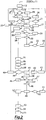
- the control process which is the object of the invention, as from a starting phase 11 and a setting at zero phase 12 of the data related to the load cell C1, performs a screening phase 13 of the temperature values detected by the resistance temperature detector T1 and resistance temperature detector T3 and of the mass value M detected and measured by the load cell C1 and a comparison 14 between the measured mass value M and full scale (maximum) value Mfs.
- a first alarm condition 15 occurs, while if M ⁇ Mfs (block 16) a further data processing (block 17) occurs with the calculation of the value of the parameter M (detected mass value) and comparison with the value Ms, which is a mass value prefixed by the load cell C1.
- the operation phase of the heat cycle of the tank S1 determines the operation of the resistor R1 (block 26) and check of such a resistor R1 (block 27) and, therefore, in case of negative check, operation of an alarm (block 28) and, in case of positive check (block 29), starting of a phase of analysis (block 30) of the resistance temperature detector T1 a phase of operation (block 31) and check (block 32) of the fan V1, which, in case of negative check, causes the operation of an another alarm (block 33).
- the analysis phase of the resistance temperature detector T1 goes on by putting the temperature value which can be detected by T1 equal to an initial value T1s, when the cycle of the resistor R1 is activated, increasing such a value of a prefixed amount of °C/min (block 34), up to reach (block 35) a value T1s equal to a maximum value T1M of heat temperature of the tank S1 for a maintenance time t1m equal to a predetermined value (and equal, for example, to five hours), to a value T1s equal to 0 (block 36) and to a predetermined and settable value of temperature Y1 which can be detected by the resistance temperature detector T1, whereby the fan V1 is stopped (block 37).
- phase of switching of the electric valve E1 and operation of the tank S1 causes the operation of the resistor R2 (phase 44) and a check phase (block 45) of the resistor R2, which, in case of negative outcome, determines the operation of an alarm (block 46), while, in case of positive outcome (block 47), determines a phase of analysis of the resistance temperature detector T2 (phase 48) and a phase of operation (phase 49) and check (phase 50) of the fan V2, which, in case of negative check, determines the activation of a related alarm (block 51).
- the activation of the fan V2 occurs for a temperature value T2s detected by T2 which can be set and increased of prefixed values of °C/min (block 52) up to a maximum value T2M of heating temperature of the tank S2 (block 53) for a pre-established maximum maintaining time interval t2m (equal, for example, to five hours), as well as up to a temperature value T2S equal to 0 (block 54) and a predetermined settable temperature value Y2 which can be detected by the three Resistance Temperature Detector (RTD) T2 for which the fan V2 is stopped (block 55).
- TTD Resistance Temperature Detector
Landscapes
- Engineering & Computer Science (AREA)
- Chemical & Material Sciences (AREA)
- Analytical Chemistry (AREA)
- General Chemical & Material Sciences (AREA)
- Oil, Petroleum & Natural Gas (AREA)
- Chemical Kinetics & Catalysis (AREA)
- Power Engineering (AREA)
- Mechanical Engineering (AREA)
- General Engineering & Computer Science (AREA)
- Drying Of Gases (AREA)
Claims (8)
- Verfahren zum Steuern eines Trockners (10), der zum Entfeuchten von Luft, die in bei Elektrogeräten verwendete Ölausdehnungsbehälter eindringt, geeignet ist, wobei der Trockner (10) mindestens ein mit Sperrflanschen versehenes äußeres Schutzgehäuse, in dem Öffnungen für austretende entfeuchtete Luft bereitgestellt sind, und mindestens einen Sumpf zum Sammeln, Transportieren und Ableiten nach außen von Kondensat umfasst, wobei das Schutzgehäuse zwei Entfeuchtungstanks oderbehälter (S1, S2) umschließt, die jeweils eine Vielzahl von Mikroöffnungen zum Einlassen der zu entfeuchtenden Luft und eine oder mehrere Öffnungen zum Auslassen der entfeuchteten Luft aufweisen, wobei jeder der zwei Entfeuchtungstanks (S1, S2) zudem ein Absorptionsmittel enthält, das geeignet ist, die Feuchtigkeit der von außen kommenden Luft zu absorbieren, und das Absorptionsmittel anhand von Widerständen (R1, R2), die jeweils im Inneren eines Entfeuchtungstanks (S1, S2) platziert sind und mit einem Belüftungsmittel (V1, V2) des Tanks (S1, S2) verbunden sind, thermisch regeneriert wird, wobei mindestens eine Kraftmessdose (C1) an einem ersten Entfeuchtungstank (S1) angebracht ist und konfiguriert ist, um den Sättigungszustand des in dem ersten Entfeuchtungstank (S1) enthaltenen Absorptionsmittels durch die Umwandlung einer angelegten Kraft in eine Änderung des elektrischen Widerstands zu bestimmen, sodass eine Detektion eines gemessenen Massenwerts (M) des Absorptionsmittels, der größer ist als ein vorab definierter Schwellenwert (Mfs, MS1), durch die Kraftmessdose (C1) die Widerstände (R1, R2) betreibt, um das Absorptionsmittel in den Originalzustand zu regenerieren,
dadurch gekennzeichnet, dass das Verfahren mindestens die folgenden Schritte umfasst:- Starten (11) und Einstellen auf null (12) von Daten, die sich auf die Kraftmessdose (C1) beziehen;- Überwachen (13) von Temperaturwerten, die von einem im Inneren des ersten Entfeuchtungstanks (S1) platzierten ersten Temperatursensors (T1) detektiert werden, durch einen im Inneren eines zweiten Entfeuchtungstanks (S2) platzierten zweiten Temperatursensor (T2) und einen im Inneren der Kraftmessdose (C1) platzierten dritten Temperatursensor (T3) und Überwachen des von der Kraftmessdose (C1) detektierten Massenwerts (M);- Vergleichen (14) des von der Kraftmessdose (C1) detektierten Massenwerts (M) mit dem vorab definierten Schwellenwert (Mfs);- Senden eines Alarmsignals (15), falls der gemessene Massenwert (M) größer ist als der vorab definierte Schwellenwert (Mfs);- Verarbeiten von Daten (17) zum Berechnen eines ersten Massenwerts (M) und zum Vergleichen des erstens Massenwerts (M) mit mindestens einem vorgegebenen zweiten Massenwert (Ms), falls der gemessene Massenwert (M) geringer ist als der vorab definierte Schwellenwert (Mfs) (16);- Überwachen (13) der Temperaturwerte, falls der gemessene Massenwert (M) geringer ist als der vorgegebene zweite Massenwert (Ms) (18);- Durchführen der folgenden Schritte, falls der gemessene Massenwert (M) für ein vorgegebenes Zeitlimit (ts) größer ist als der vorgegebene zweite Massenwert (Ms) (20) und der gemessene Massenwert (M) größer ist als ein dritter Massenwert (Ms1), der gleich einem Massenwert ist, der einen im Inneren des ersten Entfeuchtungstanks (S1) platzierten ersten Widerstand (R1) betreiben kann:∘ Überprüfen (21), ob ein zweiter Widerstand (R2) und/oder ein im Inneren des zweiten Entfeuchtungstanks (S2) platziertes Belüftungsmittel (V2) arbeitet/arbeiten,∘ und Anschalten eines elektrischen Ventils (E1) zum Betreiben (22, 23) des zweiten Entfeuchtungstanks (S2) und des an den ersten Entfeuchtungstank (S1) gekoppelten ersten Widerstands (R1). - Verfahren nach Anspruch 1, dadurch gekennzeichnet, dass das elektrische Ventil (E1) angeschaltet wird (22, 23), wenn der zweite Widerstand (R2) und/oder das zweite Belüftungsmittel (V2), die an den zweiten Entfeuchtungstank (S2) gekoppelt sind, aus ist/sind.
- Verfahren nach mindestens einem der vorstehenden Ansprüche, dadurch gekennzeichnet, dass der Schritt der Datenverarbeitung (17) durchgeführt wird, wenn der zweite Widerstand (R2) und/oder das zweite Belüftungsmittel (V2), die an den zweiten Entfeuchtungstank (S2) gekoppelt sind, an ist/sind (24).
- Verfahren nach mindestens einem der vorstehenden Ansprüche, dadurch gekennzeichnet, dass ein Alarm aktiviert wird (28), wenn der erste Widerstand (R1), der an den ersten Entfeuchtungstank (S1) gekoppelt ist, nicht arbeitet.
- Verfahren nach Anspruch 2, dadurch gekennzeichnet, dass die folgenden Schritte durchgeführt werden:- Anschalten (31) und Testen (32) des an den ersten Entfeuchtungstank (S1) gekoppelten ersten Belüftungsmittels (V1), wenn der erste Widerstand (R1) arbeitet;- Zuordnen eines Anfangswerts (T1s), eines Höchstwerts (T1M) und eines vorher festgelegten und einstellbaren Temperaturwerts (Y1) einer Erwärmungstemperatur des ersten Entfeuchtungstanks (S1), wobei die Erwärmungstemperatur von dem ersten Temperatursensor detektiert wird, wobei der Anfangswert (T1s) gleich 0 ist und dem Zeitpunkt der Aktivierung des ersten Widerstands (R1) entspricht und der vorher festgelegte und einstellbare Temperaturwert (Y1) dem Zeitpunkt des Stoppens (37) des ersten Belüftungsmittels (V1) entspricht;- Einstellen eines vorgegebenen Zeitintervalls (t1m);- Erhöhen (35) des Anfangswerts (T1s) einer vorgegebenen Temperaturmenge pro Minute bis auf (35) einen Wert, der gleich dem Höchstwert (T1M) ist, für ein Zeitintervall (T1m), das gleich dem vorgegebenen Zeitintervall ist, das eingestellt wurde;- Verändern des Temperaturwerts auf den Anfangswert (T1s);- Verändern des Temperaturwerts auf den vorher festgelegten und einstellbaren Temperaturwert (Y1);- Stoppen (37) des ersten Belüftungsmittels (V1).
- Verfahren nach Anspruch 5, dadurch gekennzeichnet, dass es die folgenden weiteren Schritte einschließt:- Detektieren (38) eines Werts (Z), der gleich dem Unterschied zwischen den Temperaturwerten, die von dem im Inneren des ersten Entfeuchtungstanks (S1) platzierten ersten Temperatursensor (T1) und von dem an die Kraftmessdose (C1) gekoppelten dritten Temperatursensor (T3) detektiert werden, ist;- Verarbeiten (39) von Daten, die von dem ersten Temperatursensor (T1) und dem dritten Temperatursensor (T3) stammen, demzufolge das Verfahren, wenn der gemessene Massenwert (M) größer ist als der dritte Massenwert (Ms1), ab dem Anschalten (22) des zweiten Entfeuchtungstanks (S2) erneut startet, während das Verfahren, wenn der gemessene Massenwert (M) geringer ist als der dritte Massenwert (Ms1), eine Schaltphase vorsieht, die es ermöglicht, das elektrische Ventil (E1) anzuschalten (42) und eine automatische Nulleinstellung der Kraftmessdose (C1) bereitzustellen (43), wobei der gemessene Massenwert (M) gleich einem vierten Massenwert (M0) ist, der gleich dem von der Kraftmessdose (C1) nach der Nulleinstellung detektierten Massenwert ist, um das Verfahren zurück zum Überwachungsschritt (13) der Temperaturwerte und des gemessenen Massenwerts (M) zu bringen.
- Verfahren nach Anspruch 6, dadurch gekennzeichnet, dass das Anschalten (42) des elektrischen Ventils (E1) eine weitere Anschalt- (44) und Testphase (45) des an den zweiten Entfeuchtungstank (S2) gekoppelten zweiten Widerstands (R2) bewirkt, um zu überprüfen, ob er arbeitet oder nicht, und ein Alarm aktiviert wird (46), wenn während der Testphase (45) des zweiten Widerstands (R2) der zweite Widerstand (R2) nicht arbeitet.
- Verfahren nach Anspruch 7, dadurch gekennzeichnet, dass, wenn die Testphase (45) des zweiten Widerstands (R2) zeigt, dass der zweite Widerstand (R2) arbeitet, das Verfahren Folgendes vorsieht:- Anschalten (49) und Testen (50) des an den zweiten Entfeuchtungstank (S2) gekoppelten zweiten Belüftungsmittels (V2) und- Zuordnen eines vorgegebenen Erwärmungstemperaturwerts (T2s), eines Erwärmungstemperaturhöchstwerts (T2M), eines vorher festgelegten dritten Erwärmungstemperaturwerts (T2S) und eines einstellbaren Erwärmungstemperaturwerts (Y2) mittels des Temperatursensors (T2) des zweiten Entfeuchtungstanks (S2), wobei der dritte Erwärmungstemperaturwert (T2S) gleich 0 ist und dem Zeitpunkt der Aktivierung des ersten Widerstands (R1) entspricht und der einstellbare Erwärmungstemperaturwert (Y2) dem Zeitpunkt des Stoppens (55) des zweiten Belüftungsmittels (V2) entspricht,- Einstellen eines vorab bestimmten maximalen Zeitintervalls (t2m);- schrittweises Erhöhen (52) des vorgegebenen Erwärmungstemperaturwerts (T2s) mit vorab festgelegten Temperaturwertbereichen pro Minute (53) bis zum Erwärmungstemperaturhöchstwert (T2M) für ein Zeitintervall, das gleich dem vorab bestimmten maximalen Zeitintervall (t2m) ist,- Verändern des Temperaturwerts (54) auf den dritten Erwärmungstemperaturwert (T2S) und/oder gleich den einstellbaren Erwärmungstemperaturwert (Y2).
Applications Claiming Priority (2)
| Application Number | Priority Date | Filing Date | Title |
|---|---|---|---|
| IT000031A ITVI20100031A1 (it) | 2010-02-12 | 2010-02-12 | Procedimento per il controllo di un essiccatore atto a deumidificare l'aria destinata a vasi di espansione dell'olio impiegati in apparecchiature elettriche |
| PCT/IT2011/000035 WO2011099046A1 (en) | 2010-02-12 | 2011-02-10 | Process for controlling dryer capable of dehumidifying air entering the oil expansion vessels used in electrical appliances |
Publications (2)
| Publication Number | Publication Date |
|---|---|
| EP2533880A1 EP2533880A1 (de) | 2012-12-19 |
| EP2533880B1 true EP2533880B1 (de) | 2021-08-04 |
Family
ID=42735229
Family Applications (1)
| Application Number | Title | Priority Date | Filing Date |
|---|---|---|---|
| EP11709214.8A Active EP2533880B1 (de) | 2010-02-12 | 2011-02-10 | Verfahren zur steuerung eines trockners zur entfeuchtung der luft, die in ölausdehnungsgefässe in elektrischen geräten eintritt |
Country Status (5)
| Country | Link |
|---|---|
| US (1) | US20130133221A1 (de) |
| EP (1) | EP2533880B1 (de) |
| CN (1) | CN102811792A (de) |
| IT (1) | ITVI20100031A1 (de) |
| WO (1) | WO2011099046A1 (de) |
Families Citing this family (3)
| Publication number | Priority date | Publication date | Assignee | Title |
|---|---|---|---|---|
| WO2017002128A1 (en) | 2015-07-01 | 2017-01-05 | Balkrishna Potnis Shrikant | Regenerating breathers system |
| CN110400678B (zh) * | 2019-06-20 | 2024-08-30 | 国网上海市电力公司 | 一种变压器呼吸器吸潮装置的自愈方法 |
| CN116492824A (zh) * | 2023-06-29 | 2023-07-28 | 常州长创力智能科技有限公司 | 一种可再生的变压器除湿过滤器及其控制方法 |
Family Cites Families (14)
| Publication number | Priority date | Publication date | Assignee | Title |
|---|---|---|---|---|
| JPS57153721A (en) * | 1981-03-18 | 1982-09-22 | Toshiba Corp | Air dehumidifying apparatus for ozone generator |
| JPS60178009A (ja) * | 1984-02-25 | 1985-09-12 | Color Toronitsuku Kk | 合成樹脂乾燥用の高温除湿空気発生方法およびその装置 |
| DE3901779C2 (de) * | 1989-01-21 | 1997-08-14 | Somos Gmbh | Verfahren und Vorrichtung zur Adsorption von Feuchtigkeit aus Gasen, insbesondere Luft |
| US5199964A (en) * | 1989-01-21 | 1993-04-06 | Graeff Roderich | Method and apparatus for adsorbing moisture from gases especially air |
| GB2232093A (en) * | 1989-05-17 | 1990-12-05 | Mcgill Europ Limited | Hydrocarbon vapour recovery. |
| US5768897A (en) * | 1992-06-16 | 1998-06-23 | Universal Dynamics Corporation | Air drying apparatus and method with high ratio gas flow to absorber weight |
| FR2818920B1 (fr) * | 2000-12-29 | 2003-09-26 | Air Liquide | Procede de traitement d'un gaz par absorption et installation correspondante |
| EP1313112B1 (de) * | 2001-11-13 | 2004-03-17 | Messko Albert Hauser GmbH & Co. KG | Luftentfeuchter für ölisolierte Transformatoren, Drosselspulen sowie Stufenschalter |
| AT412999B (de) * | 2002-11-12 | 2005-09-26 | Wiedl Alfred | Anlage zum trocknen von gütern |
| DE10357085B3 (de) | 2003-12-06 | 2005-03-17 | Maschinenfabrik Reinhausen Gmbh | Verfahren zur Luftentfeuchtung und Luftentfeuchter für ölisolierte Transformatoren, Drosselspulen sowie Stufenschalter |
| ITVR20060030A1 (it) * | 2006-02-10 | 2007-08-11 | Moretto Spa | Impianto e procedimento di deumidificazione a funzionamento flessibile particolarmente per materiali granulari. |
| US20070272083A1 (en) * | 2006-03-30 | 2007-11-29 | Ross Hoge | Filter saturation control system |
| ITVI20070222A1 (it) * | 2007-08-07 | 2009-02-08 | Comem Spa | Essiccatore perfezionato per deumidificare l'aria destinata a vasi di espansione dell'olio impiegati in apparecchiature elettriche. |
| WO2010102308A1 (en) * | 2009-03-06 | 2010-09-10 | Sensortech Corporation | Load cell |
-
2010
- 2010-02-12 IT IT000031A patent/ITVI20100031A1/it unknown
-
2011
- 2011-02-10 EP EP11709214.8A patent/EP2533880B1/de active Active
- 2011-02-10 WO PCT/IT2011/000035 patent/WO2011099046A1/en not_active Ceased
- 2011-02-10 US US13/578,072 patent/US20130133221A1/en not_active Abandoned
- 2011-02-10 CN CN2011800089378A patent/CN102811792A/zh active Pending
Non-Patent Citations (1)
| Title |
|---|
| None * |
Also Published As
| Publication number | Publication date |
|---|---|
| EP2533880A1 (de) | 2012-12-19 |
| CN102811792A (zh) | 2012-12-05 |
| ITVI20100031A1 (it) | 2011-08-13 |
| WO2011099046A1 (en) | 2011-08-18 |
| US20130133221A1 (en) | 2013-05-30 |
Similar Documents
| Publication | Publication Date | Title |
|---|---|---|
| TWI868879B (zh) | 衣物處理裝置的控制方法、裝置、衣物處理裝置及儲存介質 | |
| EP2175965B1 (de) | Verbesserter trockner zur luchtentfeuchtung für ölausdehnungsgefäss für elektrische einrichtungen | |
| CN103090460A (zh) | 用于供暖、通风或空气调节系统的冷凝水排放方法和装置 | |
| CN102154805A (zh) | 干衣机风道堵塞判断方法及干衣机 | |
| CN103882664B (zh) | 衣物烘干机及其工作方法 | |
| WO2016019661A1 (zh) | 一种排水装置、方法及除湿机 | |
| JP2013252474A (ja) | 電気機械用ガス乾燥器 | |
| US20130133221A1 (en) | Process for controlling dryer capable of dehumidifying air entering the oil expansion vessels used in electrical appliances | |
| CN113790572B (zh) | 一种冰箱的控制方法、装置、存储介质及冰箱 | |
| JP2012076060A (ja) | 除湿装置 | |
| EP3086060A1 (de) | Abtauverfahren und abtauvorrichtung für kältegerät oder klimaanlagenvorrichtung | |
| JP2009171998A (ja) | 洗濯乾燥機 | |
| CN205119419U (zh) | 无冷凝水排放的机柜空调 | |
| JP2011158121A (ja) | 空気調和機 | |
| JP2014181851A (ja) | 除湿装置 | |
| CN103837313A (zh) | 一种蒸柜气密性自动检测系统及方法 | |
| CN107951378B (zh) | 压力烹饪器具及其控制方法 | |
| CN104265612A (zh) | 水泵控制方法 | |
| CN105318509B (zh) | 机柜空调的控制系统及控制方法 | |
| JP2016188731A (ja) | 空気調和機 | |
| KR100607130B1 (ko) | 증기발생용 히터의 고장알림 장치 및 그 방법 | |
| KR20140076662A (ko) | 공기조화장치 및 공기조화장치의 배수방법 | |
| JP7455048B2 (ja) | 空調装置 | |
| JP7781115B2 (ja) | 空気処理装置 | |
| CN112567887B (zh) | 用于运行家用烹饪器具的方法和家用烹饪器具 |
Legal Events
| Date | Code | Title | Description |
|---|---|---|---|
| PUAI | Public reference made under article 153(3) epc to a published international application that has entered the european phase |
Free format text: ORIGINAL CODE: 0009012 |
|
| 17P | Request for examination filed |
Effective date: 20120720 |
|
| AK | Designated contracting states |
Kind code of ref document: A1 Designated state(s): AL AT BE BG CH CY CZ DE DK EE ES FI FR GB GR HR HU IE IS IT LI LT LU LV MC MK MT NL NO PL PT RO RS SE SI SK SM TR |
|
| DAX | Request for extension of the european patent (deleted) | ||
| RAP1 | Party data changed (applicant data changed or rights of an application transferred) |
Owner name: ABB SCHWEIZ AG |
|
| STAA | Information on the status of an ep patent application or granted ep patent |
Free format text: STATUS: EXAMINATION IS IN PROGRESS |
|
| 17Q | First examination report despatched |
Effective date: 20181015 |
|
| RAP1 | Party data changed (applicant data changed or rights of an application transferred) |
Owner name: ABB SCHWEIZ AG |
|
| RAP1 | Party data changed (applicant data changed or rights of an application transferred) |
Owner name: ABB POWER GRIDS SWITZERLAND AG |
|
| RIC1 | Information provided on ipc code assigned before grant |
Ipc: B01D 53/26 20060101AFI20210115BHEP Ipc: B01D 53/04 20060101ALI20210115BHEP Ipc: H01F 27/14 20060101ALI20210115BHEP Ipc: G01N 5/02 20060101ALI20210115BHEP |
|
| GRAP | Despatch of communication of intention to grant a patent |
Free format text: ORIGINAL CODE: EPIDOSNIGR1 |
|
| STAA | Information on the status of an ep patent application or granted ep patent |
Free format text: STATUS: GRANT OF PATENT IS INTENDED |
|
| INTG | Intention to grant announced |
Effective date: 20210226 |
|
| RAP1 | Party data changed (applicant data changed or rights of an application transferred) |
Owner name: COMEM S.R.L. |
|
| RIN1 | Information on inventor provided before grant (corrected) |
Inventor name: CAROLLO, CARLO Inventor name: TONIN, ANDREA |
|
| GRAS | Grant fee paid |
Free format text: ORIGINAL CODE: EPIDOSNIGR3 |
|
| GRAA | (expected) grant |
Free format text: ORIGINAL CODE: 0009210 |
|
| STAA | Information on the status of an ep patent application or granted ep patent |
Free format text: STATUS: THE PATENT HAS BEEN GRANTED |
|
| AK | Designated contracting states |
Kind code of ref document: B1 Designated state(s): AL AT BE BG CH CY CZ DE DK EE ES FI FR GB GR HR HU IE IS IT LI LT LU LV MC MK MT NL NO PL PT RO RS SE SI SK SM TR |
|
| REG | Reference to a national code |
Ref country code: GB Ref legal event code: FG4D |
|
| REG | Reference to a national code |
Ref country code: AT Ref legal event code: REF Ref document number: 1416389 Country of ref document: AT Kind code of ref document: T Effective date: 20210815 |
|
| REG | Reference to a national code |
Ref country code: CH Ref legal event code: EP |
|
| REG | Reference to a national code |
Ref country code: DE Ref legal event code: R096 Ref document number: 602011071487 Country of ref document: DE |
|
| REG | Reference to a national code |
Ref country code: IE Ref legal event code: FG4D |
|
| REG | Reference to a national code |
Ref country code: LT Ref legal event code: MG9D |
|
| REG | Reference to a national code |
Ref country code: NL Ref legal event code: MP Effective date: 20210804 |
|
| REG | Reference to a national code |
Ref country code: AT Ref legal event code: MK05 Ref document number: 1416389 Country of ref document: AT Kind code of ref document: T Effective date: 20210804 |
|
| PG25 | Lapsed in a contracting state [announced via postgrant information from national office to epo] |
Ref country code: SE Free format text: LAPSE BECAUSE OF FAILURE TO SUBMIT A TRANSLATION OF THE DESCRIPTION OR TO PAY THE FEE WITHIN THE PRESCRIBED TIME-LIMIT Effective date: 20210804 Ref country code: HR Free format text: LAPSE BECAUSE OF FAILURE TO SUBMIT A TRANSLATION OF THE DESCRIPTION OR TO PAY THE FEE WITHIN THE PRESCRIBED TIME-LIMIT Effective date: 20210804 Ref country code: NO Free format text: LAPSE BECAUSE OF FAILURE TO SUBMIT A TRANSLATION OF THE DESCRIPTION OR TO PAY THE FEE WITHIN THE PRESCRIBED TIME-LIMIT Effective date: 20211104 Ref country code: PT Free format text: LAPSE BECAUSE OF FAILURE TO SUBMIT A TRANSLATION OF THE DESCRIPTION OR TO PAY THE FEE WITHIN THE PRESCRIBED TIME-LIMIT Effective date: 20211206 Ref country code: RS Free format text: LAPSE BECAUSE OF FAILURE TO SUBMIT A TRANSLATION OF THE DESCRIPTION OR TO PAY THE FEE WITHIN THE PRESCRIBED TIME-LIMIT Effective date: 20210804 Ref country code: ES Free format text: LAPSE BECAUSE OF FAILURE TO SUBMIT A TRANSLATION OF THE DESCRIPTION OR TO PAY THE FEE WITHIN THE PRESCRIBED TIME-LIMIT Effective date: 20210804 Ref country code: FI Free format text: LAPSE BECAUSE OF FAILURE TO SUBMIT A TRANSLATION OF THE DESCRIPTION OR TO PAY THE FEE WITHIN THE PRESCRIBED TIME-LIMIT Effective date: 20210804 Ref country code: AT Free format text: LAPSE BECAUSE OF FAILURE TO SUBMIT A TRANSLATION OF THE DESCRIPTION OR TO PAY THE FEE WITHIN THE PRESCRIBED TIME-LIMIT Effective date: 20210804 Ref country code: BG Free format text: LAPSE BECAUSE OF FAILURE TO SUBMIT A TRANSLATION OF THE DESCRIPTION OR TO PAY THE FEE WITHIN THE PRESCRIBED TIME-LIMIT Effective date: 20211104 Ref country code: LT Free format text: LAPSE BECAUSE OF FAILURE TO SUBMIT A TRANSLATION OF THE DESCRIPTION OR TO PAY THE FEE WITHIN THE PRESCRIBED TIME-LIMIT Effective date: 20210804 |
|
| PG25 | Lapsed in a contracting state [announced via postgrant information from national office to epo] |
Ref country code: PL Free format text: LAPSE BECAUSE OF FAILURE TO SUBMIT A TRANSLATION OF THE DESCRIPTION OR TO PAY THE FEE WITHIN THE PRESCRIBED TIME-LIMIT Effective date: 20210804 Ref country code: LV Free format text: LAPSE BECAUSE OF FAILURE TO SUBMIT A TRANSLATION OF THE DESCRIPTION OR TO PAY THE FEE WITHIN THE PRESCRIBED TIME-LIMIT Effective date: 20210804 Ref country code: GR Free format text: LAPSE BECAUSE OF FAILURE TO SUBMIT A TRANSLATION OF THE DESCRIPTION OR TO PAY THE FEE WITHIN THE PRESCRIBED TIME-LIMIT Effective date: 20211105 |
|
| PG25 | Lapsed in a contracting state [announced via postgrant information from national office to epo] |
Ref country code: NL Free format text: LAPSE BECAUSE OF FAILURE TO SUBMIT A TRANSLATION OF THE DESCRIPTION OR TO PAY THE FEE WITHIN THE PRESCRIBED TIME-LIMIT Effective date: 20210804 |
|
| PG25 | Lapsed in a contracting state [announced via postgrant information from national office to epo] |
Ref country code: DK Free format text: LAPSE BECAUSE OF FAILURE TO SUBMIT A TRANSLATION OF THE DESCRIPTION OR TO PAY THE FEE WITHIN THE PRESCRIBED TIME-LIMIT Effective date: 20210804 |
|
| REG | Reference to a national code |
Ref country code: DE Ref legal event code: R097 Ref document number: 602011071487 Country of ref document: DE |
|
| PG25 | Lapsed in a contracting state [announced via postgrant information from national office to epo] |
Ref country code: SM Free format text: LAPSE BECAUSE OF FAILURE TO SUBMIT A TRANSLATION OF THE DESCRIPTION OR TO PAY THE FEE WITHIN THE PRESCRIBED TIME-LIMIT Effective date: 20210804 Ref country code: SK Free format text: LAPSE BECAUSE OF FAILURE TO SUBMIT A TRANSLATION OF THE DESCRIPTION OR TO PAY THE FEE WITHIN THE PRESCRIBED TIME-LIMIT Effective date: 20210804 Ref country code: RO Free format text: LAPSE BECAUSE OF FAILURE TO SUBMIT A TRANSLATION OF THE DESCRIPTION OR TO PAY THE FEE WITHIN THE PRESCRIBED TIME-LIMIT Effective date: 20210804 Ref country code: EE Free format text: LAPSE BECAUSE OF FAILURE TO SUBMIT A TRANSLATION OF THE DESCRIPTION OR TO PAY THE FEE WITHIN THE PRESCRIBED TIME-LIMIT Effective date: 20210804 Ref country code: CZ Free format text: LAPSE BECAUSE OF FAILURE TO SUBMIT A TRANSLATION OF THE DESCRIPTION OR TO PAY THE FEE WITHIN THE PRESCRIBED TIME-LIMIT Effective date: 20210804 Ref country code: AL Free format text: LAPSE BECAUSE OF FAILURE TO SUBMIT A TRANSLATION OF THE DESCRIPTION OR TO PAY THE FEE WITHIN THE PRESCRIBED TIME-LIMIT Effective date: 20210804 |
|
| PLBE | No opposition filed within time limit |
Free format text: ORIGINAL CODE: 0009261 |
|
| STAA | Information on the status of an ep patent application or granted ep patent |
Free format text: STATUS: NO OPPOSITION FILED WITHIN TIME LIMIT |
|
| 26N | No opposition filed |
Effective date: 20220506 |
|
| PG25 | Lapsed in a contracting state [announced via postgrant information from national office to epo] |
Ref country code: SI Free format text: LAPSE BECAUSE OF FAILURE TO SUBMIT A TRANSLATION OF THE DESCRIPTION OR TO PAY THE FEE WITHIN THE PRESCRIBED TIME-LIMIT Effective date: 20210804 |
|
| PG25 | Lapsed in a contracting state [announced via postgrant information from national office to epo] |
Ref country code: MC Free format text: LAPSE BECAUSE OF FAILURE TO SUBMIT A TRANSLATION OF THE DESCRIPTION OR TO PAY THE FEE WITHIN THE PRESCRIBED TIME-LIMIT Effective date: 20210804 |
|
| REG | Reference to a national code |
Ref country code: CH Ref legal event code: PL |
|
| REG | Reference to a national code |
Ref country code: BE Ref legal event code: MM Effective date: 20220228 |
|
| GBPC | Gb: european patent ceased through non-payment of renewal fee |
Effective date: 20220210 |
|
| PG25 | Lapsed in a contracting state [announced via postgrant information from national office to epo] |
Ref country code: LU Free format text: LAPSE BECAUSE OF NON-PAYMENT OF DUE FEES Effective date: 20220210 |
|
| PG25 | Lapsed in a contracting state [announced via postgrant information from national office to epo] |
Ref country code: FR Free format text: LAPSE BECAUSE OF NON-PAYMENT OF DUE FEES Effective date: 20220228 |
|
| PG25 | Lapsed in a contracting state [announced via postgrant information from national office to epo] |
Ref country code: LI Free format text: LAPSE BECAUSE OF NON-PAYMENT OF DUE FEES Effective date: 20220228 Ref country code: GB Free format text: LAPSE BECAUSE OF NON-PAYMENT OF DUE FEES Effective date: 20220210 Ref country code: CH Free format text: LAPSE BECAUSE OF NON-PAYMENT OF DUE FEES Effective date: 20220228 |
|
| PG25 | Lapsed in a contracting state [announced via postgrant information from national office to epo] |
Ref country code: BE Free format text: LAPSE BECAUSE OF NON-PAYMENT OF DUE FEES Effective date: 20220228 |
|
| P01 | Opt-out of the competence of the unified patent court (upc) registered |
Effective date: 20230519 |
|
| PG25 | Lapsed in a contracting state [announced via postgrant information from national office to epo] |
Ref country code: HU Free format text: LAPSE BECAUSE OF FAILURE TO SUBMIT A TRANSLATION OF THE DESCRIPTION OR TO PAY THE FEE WITHIN THE PRESCRIBED TIME-LIMIT; INVALID AB INITIO Effective date: 20110210 |
|
| PG25 | Lapsed in a contracting state [announced via postgrant information from national office to epo] |
Ref country code: MK Free format text: LAPSE BECAUSE OF FAILURE TO SUBMIT A TRANSLATION OF THE DESCRIPTION OR TO PAY THE FEE WITHIN THE PRESCRIBED TIME-LIMIT Effective date: 20210804 Ref country code: CY Free format text: LAPSE BECAUSE OF FAILURE TO SUBMIT A TRANSLATION OF THE DESCRIPTION OR TO PAY THE FEE WITHIN THE PRESCRIBED TIME-LIMIT Effective date: 20210804 |
|
| PG25 | Lapsed in a contracting state [announced via postgrant information from national office to epo] |
Ref country code: MT Free format text: LAPSE BECAUSE OF FAILURE TO SUBMIT A TRANSLATION OF THE DESCRIPTION OR TO PAY THE FEE WITHIN THE PRESCRIBED TIME-LIMIT Effective date: 20210804 |
|
| PGFP | Annual fee paid to national office [announced via postgrant information from national office to epo] |
Ref country code: IE Payment date: 20251209 Year of fee payment: 16 |
|
| PGFP | Annual fee paid to national office [announced via postgrant information from national office to epo] |
Ref country code: DE Payment date: 20251216 Year of fee payment: 16 |
|
| PGFP | Annual fee paid to national office [announced via postgrant information from national office to epo] |
Ref country code: IT Payment date: 20260115 Year of fee payment: 16 |
|
| PGFP | Annual fee paid to national office [announced via postgrant information from national office to epo] |
Ref country code: TR Payment date: 20260209 Year of fee payment: 16 |