EP2533110A2 - Timepiece provided with a device for the control of functions and/or time indications - Google Patents
Timepiece provided with a device for the control of functions and/or time indications Download PDFInfo
- Publication number
- EP2533110A2 EP2533110A2 EP12182768A EP12182768A EP2533110A2 EP 2533110 A2 EP2533110 A2 EP 2533110A2 EP 12182768 A EP12182768 A EP 12182768A EP 12182768 A EP12182768 A EP 12182768A EP 2533110 A2 EP2533110 A2 EP 2533110A2
- Authority
- EP
- European Patent Office
- Prior art keywords
- selection
- cam
- winding
- functions
- indications
- Prior art date
- Legal status (The legal status is an assumption and is not a legal conclusion. Google has not performed a legal analysis and makes no representation as to the accuracy of the status listed.)
- Granted
Links
Images


Classifications
-
- G—PHYSICS
- G04—HOROLOGY
- G04B—MECHANICALLY-DRIVEN CLOCKS OR WATCHES; MECHANICAL PARTS OF CLOCKS OR WATCHES IN GENERAL; TIME PIECES USING THE POSITION OF THE SUN, MOON OR STARS
- G04B27/00—Mechanical devices for setting the time indicating means
- G04B27/02—Mechanical devices for setting the time indicating means by making use of the winding means
- G04B27/06—Mechanical devices for setting the time indicating means by making use of the winding means with rocking bar
- G04B27/065—Changing the winding position to the setting position and vice versa is done with an independant part of the winding or setting mechanism
Definitions
- the present invention relates to a timepiece equipped with a function control device and / or time indications comprising a member for selecting each function and / or time indication to be actuated and a member for adjusting said functions or selected time indications.
- the functions and / or time indications are set using the winding stem.
- the winding stem In the pushed-in position toward the center of the timepiece, in the case of a mechanical watch, the winding stem controls the winding of the spring and in a second axial position, resulting from an outward pull, the rod The winding is connected to the clock train to set the hour and minute indications.
- a date indicator In which the winding stem can be moved to a third position to set the date indicator or days.
- the object of the present invention is to overcome, at least in part, the disadvantages of known solutions.
- this invention relates to a timepiece provided with a device for adjusting functions and / or time indications according to claim 1.
- the adjustment member is in kinematic connection with a second cam having a profile with n (n ⁇ 2) times two state levels 0, 1, respectively corresponding to a state of non-adjustment and to a state of adjustment , the adjusting device comprising means for detecting the concordance of two state levels 1 on the two respective cams.
- this timepiece provided with this adjustment device essentially come from the separation between the selection and the actual setting. There is only possible correction if there is selection of the function and / or the indication to be adjusted, or concordance of two states 1 of the two cams in the case of the preferred embodiment.
- the order in which the cams are actuated is indifferent.
- the choice of the function and / or indication to be adjusted is achieved through a rotating bezel.
- the number of functions and / or indications to be regulated can be high, the telescope can rotate 360 °.
- Each function and / or indication that it is desired to adjust can therefore advantageously be identified by a mark carried by the rotating bezel and brought opposite a fixed indication and corresponding to the function and / or indication to be adjusted. .
- the user always knows what action he will perform with the help of the adjustment member.
- the adjusting member is constituted by a winding stem with two positions, a position of which is a winding position and the second a setting position.
- a single rod with two positions makes it possible to adjust a number of functions and / or time indications substantially greater than its unique setting position.
- this rod no longer needs to be associated with a sliding pinion and it can advantageously be associated with a disengaging system axially separating two co-axial mobiles of the winding train.
- the removal of the sliding pinion also avoids the risk of jamming between the sliding pinion and the clockwork.
- the means for detecting the concordance of two state levels 1 on both cams can be actuated by springs and not by a force transmitted by the function setting rod and / or selected time indications.
- this timepiece equipped with this adjustment device has above all high reliability and is easy to use, even if the number of functions and / or indications to be adjusted is significantly higher than in most watches of the state of the art.
- the device comprises at least one selection cam C 1 which has a binary profile at n (n ⁇ 2) times two state levels 0 and 1.
- the selection cam C 1 is mounted pivotally about an axis of rotation
- the level 0 forms a circular surface centered on the axis of rotation and corresponding to a state of non-selection
- the level 1 forms at least two cavities in the circular surface, corresponding to selection states.
- the adjustment device is designed to set three different time indications, each comprising means bearing against the cam C 1 to connect the time indication to be adjusted to a control member.
- the aforementioned means are represented in the form of levers L 1 , L 2 , L 3 , pivotally mounted about axes A 1 , A 2 , respectively A 3 and pressed against the selection cam C 1 by return springs RE 1 , RE 2 , respectively RE 3 .
- Means not represented in the Figures 1 and 2 , but illustrated hereinafter are intended to allow the selection cam C 1 to be moved angularly to selectively bring its hollow corresponding to the state 1 towards one of the levers L 1 , L 2 , L 3 , to connect the selected function or time indication to a setting member.
- this invention has been proposed to use as a control member a winding stem T with two axial positions, an axial position pushed towards the movement of the timepiece, corresponding to the position traditional winding of the mainspring in the case of a mechanical timepiece and an axial position where the stem T is pulled outwards and traditionally corresponding to the time setting position.
- this second position corresponds to a setting position of one of the functions or time indications selected or to be selected.
- this rod T is in desmodromic connection with a second cam C 2 which, in this example, is a cam of generally circular and concentric with the selection cam C 1 .
- the desmodromic link between the cam C 2 and the winding stem T is formed by a pull rod Ti pivotally mounted about an axis A 4 and one arm of which is engaged with the winding stem T, while the other arm carries a pin mounted with clearance in an elongate opening of an arm C 2 'integral with the cam C 2 .
- This cam C 2 has n (n ⁇ 2) times two levels of states 0 and 1, but here it has as many states 1 formed by valleys as there are functions and / or hourly indications. to settle.
- These hollows corresponding to the states 1 are distributed at angular distances from each other corresponding to the respective angular distances separating the ends of the levers L 1 , L 2 , L 3 , resting against the selection cam C 1 and simultaneously against the cam C 2 , the circular parts of these two cams corresponding to states 0 being of the same radius.
- the cam C 2 is thus capable of occupying two angular positions around the axis of rotation of the cams C 1 , C 2 , one corresponding to the winding stem T in pushed axial position, in which the recesses of the states 1 of the cam C 2 are not opposite the ends of the respective levers L 1 , L 2 , L 3 , the other corresponding to the position of the winding stem T in position drawn in which the hollow states 1 of the cam C 2 are opposite the respective ends of the levers L 1 , L 2 , L 3 .
- Two O-rings J are arranged between the control shaft A and the wall of the housing cylindrical LM.
- the upper end of the shaft terminates in a locking square CV to prevent free rotation of the control shaft A.
- a Maltese cross CM is fixed below the locking square CV and is intended to be driven 2 x 90 ° when passing pairs of drive pins G angularly distributed on the rotating bezel L to engage with the Maltese cross CM.
- the position of each pair of pins G corresponds to the selection of a time indication to be adjusted. Therefore, a marker can be fixed on the rotating bezel L and information relating to the selected time indications to be set can be arranged on the dial or on a flange surrounding the dial for example, to know in which position of selection or not selection is the rotating bezel L.
- the other end of the control shaft A opens into a portion LM 1 of the housing LM of the middle part M which opens in the internal lateral face of the middle part M.
- This other end of the control shaft A is integral a pinion provided with four arms D which penetrate in turn inside the middle part M to drive the arms of a selector S ( Figures 8 to 11 ) of the time setting device.
- This selector S is integral with a reference R 1 meshing with a return R 2 integral with the selection cam C 1 and a positioning cam C 3 .
- the winding stem T is engaged with an arm of the zipper Ti, as explained above. Its inner end has a section III of polygonal shape complementary to that of the axial opening of a winding pinion P of cylindrical general shape of which a front teeth D f meshes with a return R 3 integral with a reference R 6 first movable adjustment wheel.
- the winding pinion P further includes a corner tooth D c meshing with a toothing angle of a winding crown RC 1 provided with an edge toothing Breguet D into engagement with the edge D of Breguet toothing a second winding crown RC 2 secured to a crown shaft AC and axially pressed against the first crown wheel RC 1 by a spring RES 1 .
- This second winding crown RC 2 forms a clutch movable clutch mechanism between the winding stem T and the winding gear train.
- one end of the crown shaft AC is pressed by the spring RES 1 against a first portion I of smaller diameter of the winding stem T when it is in its pushed position corresponding to its winding position ( figure 6 ).
- This first portion I is connected by a frustoconical surface to a second portion II of larger diameter, so that by pulling the winding stem T outwards, the crown shaft AC is raised against the pressing the return spring RES 1 so that the two Breguet teeth of field D a are separated from one another, interrupting the kinematic connection between the winding rod T and the barrel ratchet RO.
- the winding pinion P is not sliding, only the winding stem T slides inside the pinion P which is fixed relative to the longitudinal axis of the winding stem T.
- the first mobile R 3 , R 6 of the adjustment train is constantly driven, regardless of the axial position of the winding stem T.
- the zipper Ti moved the cam C 2 to the position illustrated by the Figures 9-11 , which means that the three recesses corresponding to the state 1 of the cam C 2 are respectively opposite the ends of the levers L 1 , L 2 , L 3 .
- the drive of the selection cam C 1 is obtained by the rotation of the rotating bezel L and pairs of pins G which engage with the Maltese cross CM integral with the control shaft A, this which has the effect of driving the selector arms S ( figure 8 ) integral with the return R 1 meshing with the return R 2 integral with the selection cam C 1 .
- the positioning member C 3 integral with the selection cam C 1 is engaged with a positioning jumper SP and serves to maintain the selection cam C 1 in the position corresponding to the control of the function or the setting of the time indication selected.
- the figure 8 illustrates the different members of the adjusting device in a position in which no adjustment can be made.
- This adjustment device comprises two flip-flops B 1 and B 2 which pivot respectively about the axes PB 1 , PB 2 .
- the flip-flop B 1 is the time-setting flip-flop and carries three references, the reference R 3 concentric with the pivot axis PB 1 of this flip-flop B 1 and constantly in engagement with the front set of teeth D f of the winding pinion. P and the references R 4 , R 5 .
- This flip-flop B 1 is connected to the lever L 1 by a articulation G 1 , this lever L 1 being pivotally mounted about an axis A 1 .
- the flip-flop B 2 carries four references, the reference R 7 coaxial with the pivot axis PB 2 , constantly in contact with the coaxial return R 6 and integral with the reference R 3 , the reference R 8 meshing with the reference R 7 and with a return R 9 , coaxial and integral with a reference R 10 and a date corrector COR 1 .
- This date corrector COR 1 is intended to come into engagement with the internal toothing of a date disk DIS in a tilting position of the flip-flop B 2
- the return R 10 is intended to engage in another position of the flip-flop B 2 with a corrective reference of the days of the week COR 2 which meshes with a wheel of the days R j integral with a disc bearing the names of the days J.
- the figure 9 more particularly illustrates the part of the adjustment device relating to the setting of the date disk DIS.
- the lever L 2 pivotally mounted around a pad A 2, 3 is pressed by the spring RE 2 in the recesses of the cams C 1 , C 2 whose angular positions have been made to coincide.
- the three recesses of the cam C 2 were placed in front of the three levers L 1 , L 2 , L 3 by the winding stem T placed in its pulled position and the recess O 2 of the selection cam C 1 was brought opposite the adjacent end of the lever L 2 .
- each cam C 1 , C 2 Since a recess of each cam C 1 , C 2 has the same angular position opposite the adjacent end of the lever L 2 , the latter pivots about its pivot axis A 2, 3 under the pressure exerted by the RE 2 spring. During its pivoting, the pin G 2 of the lever causes the rocker B 2 in the position illustrated by the figure 9 , in which the arms of the correction mobile COR 1 penetrate into the internal toothing of the date disk DIS. Therefore, the rotation of the winding stem T is transmitted to the correction mobile COR 1 which can drive the disk DIS date in one direction or the other.
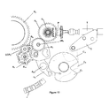
- the figure 10 illustrates more particularly the part of the adjustment device relating to the setting of the disc of the days of the week J.
- the cam C 2 is always in the position corresponding to the winding stem T pulled with the winding crowns RC 1 , RC 2 disengaged ( position illustrated by the figure 7 ).
- the selection cam C 1 is moved using the rotating bezel L in the angular position illustrated by the figure 10 , in which the hollow O 2 is opposite the adjacent end of the lever L 3 coinciding with a recess of the cam C 2 . This allows the lever L 3 to switch under the pressure of the spring RE 3 . In this position, the flip-flop B 2 becomes free to pivot about its axis PB 2 .
- the reference R 9 also rotates in the clockwise direction so that a torque is transmitted to the flip-flop B 2 to rotate it also in the direction of clockwise, thus putting the reference R 10 in contact with the corrective return COR 2 which drives the wheel of the days R j in the direction of the needles d 'a watch.
- the correction of days can only be done in this direction since in the opposite direction, the flip-flop B 2 rotates in the opposite direction of that of clockwise. However, it is stopped by the pin G 2 integral with the lever L 2 so that the arms of the calendar correction mobile COR 1 can not come into contact with the toothing of the date disk DIS.
- the figure 11 illustrates the part of the adjustment device intended for setting the time.
- a second selection recess O 1 has been formed on the selection cam C 1 used exclusively for the setting the time, this to reduce the rotation angle of the rotating bezel L.
- the cam C 2 is necessary only to the extent that the control member is a two-position member, as in the example described where the winding stem which normally has two degrees of freedom, in rotation and in translation is used both as a control member in its degree of freedom in rotation and as selection member in its degree of freedom in axial translation. It then takes a second cam that plays somehow the role of a mechanical switch. If the cam C 2 is in a position, no adjustment is possible to avoid interfering with the other function of the winding stem T. If the cam C 2 is in its other position, all settings are possible, the selector to choose from the possible settings, the one that is desired.
- timepiece according to the invention can be both mechanical and electronic.
Landscapes
- Physics & Mathematics (AREA)
- General Physics & Mathematics (AREA)
- Electric Clocks (AREA)
- Electromechanical Clocks (AREA)
- Measurement Of Predetermined Time Intervals (AREA)
Abstract
Description
La présente invention se rapporte à une pièce d'horlogerie munie d'un dispositif de commande de fonctions et/ou d'indications horaires comprenant un organe de sélection de chaque fonction et/ou indication horaire à actionner et un organe de réglage desdites fonctions ou indications horaires sélectionnées.The present invention relates to a timepiece equipped with a function control device and / or time indications comprising a member for selecting each function and / or time indication to be actuated and a member for adjusting said functions or selected time indications.
De la manière la plus courante, les fonctions et/ou indications horaires sont réglées à l'aide de la tige de remontoir. En position poussée vers le centre de la pièce d'horlogerie, dans le cas d'une montre mécanique, la tige de remontoir commande le remontage du ressort et dans une seconde position axiale, résultant d'une traction vers l'extérieur, la tige de remontoir est mise en relation avec le rouage de minuterie pour régler les indications d'heures et de minutes. Il existe encore des montres possédant un indicateur des quantièmes, dans lesquelles la tige de remontoir peut être déplacée dans une troisième position pour régler l'indicateur des quantièmes ou bien des jours.In the most common way, the functions and / or time indications are set using the winding stem. In the pushed-in position toward the center of the timepiece, in the case of a mechanical watch, the winding stem controls the winding of the spring and in a second axial position, resulting from an outward pull, the rod The winding is connected to the clock train to set the hour and minute indications. There are still watches with a date indicator, in which the winding stem can be moved to a third position to set the date indicator or days.
C'est pratiquement la limite des fonctions et/ou indications horaires que l'on peut régler avec la seule tige de remontoir. En effet, même si il était possible d'augmenter davantage le nombre de positions de la tige de remontoir, l'utilisateur aurait du mal à mémoriser la fonction de chaque position, sans compter qu'il aurait aussi du mal à savoir dans quelle position se trouve la tige de remontoir. Lorsqu'il y a plus de deux indications à régler, il faut que l'utilisateur soit informé quant à la nature de la fonction et/ou de l'indication horaire qu'il est en train de régler.This is practically the limit of the functions and / or time indications that can be adjusted with the single winding stem. Indeed, even if it was possible to further increase the number of positions of the winding stem, the user would have difficulty in memorizing the function of each position, not to mention that it would also be difficult to know in which position there is the winding stem. When there are more than two indications to be adjusted, the user must be informed as to the nature of the function and / or the time indication that he is setting.
On a déjà proposé dans le CH 228 de séparer la sélection de fonction entre le remontage et la mise à l'heure et l'exécution de la fonction, en utilisant une lunette tournante pour commander une bascule munie d'une roue intermédiaire qui peut être mise en prise soit avec le rochet de remontage soit avec le rouage de minuterie. La tige de remontoir qui a une position axiale fixe actionne soit le remontage soit la mise à l'heure en fonction de la position de la bascule commandée par la lunette. Compte tenu de l'utilisation d'une bascule, le nombre de fonctions qui peut être corrigé à l'aide de cette solution est évidemment très limité. En fait, dans la solution décrite dans ce document, on remplace la tige à deux positions avec tirette et pignon coulant par une tige à position axiale unique et bascule commandée par la lunette, mais on n'augmente pas le nombre de fonctions à régler.It has already been proposed in CH 228 to separate the function selection between reassembly and time setting and execution. of the function, using a rotating bezel to control a rocker equipped with an intermediate wheel that can be engaged with either the winding ratchet or with the timer train. The winding stem which has a fixed axial position actuates either the reassembly or setting time according to the position of the rocker controlled by the telescope. Given the use of a rocker, the number of functions that can be corrected with this solution is obviously very limited. In fact, in the solution described in this document, the two-position rod with pull-and-sliding pinion is replaced by a rod with a single axial position and a rocker controlled by the telescope, but the number of functions to be adjusted is not increased.
Il existe plusieurs documents qui proposent d'utiliser une lunette tournante munie d'une denture annulaire en prise avec un pignon à axe radial pour régler une fonction horaire, soit le fuseau horaire, la date, le jour, le mois ou encore l'année. Une de ces solutions est décrite dans le
D'autres solutions proposent d'ajouter des possibilités de réglage d'indications horaires supplémentaires par l'adjonction de boutons poussoirs indépendants ce qui nuit à l'esthétique de la montre et limite donc forcément le nombre d'indications réglables de cette manière.Other solutions propose to add the possibility of setting additional time indications by the addition of independent pushbuttons which affects the aesthetics of the watch and necessarily limits the number of indications adjustable in this way.
On a encore proposé d'utiliser une lunette tournante pour sélectionner les différents réglages des indications horaires dans le
Enfin, dans le
On peut constater que le réglage de plusieurs fonctions et/ou indications horaires pose un problème qui a de la peine à trouver une solution satisfaisante.It can be seen that the setting of several functions and / or time indications is a problem which is difficult to find a satisfactory solution.
Le but de la présente invention est de remédier, au moins en partie aux inconvénients des solutions connues.The object of the present invention is to overcome, at least in part, the disadvantages of known solutions.
A cet effet, cette invention a pour objet une pièce d'horlogerie munie d'un dispositif de réglage de fonctions et/ou d'indications horaires selon la revendication 1.For this purpose, this invention relates to a timepiece provided with a device for adjusting functions and / or time indications according to claim 1.
De préférence, l'organe de réglage est en liaison cinématique avec une deuxième came comportant un profil à n (n≥2) fois deux niveaux d'états 0, 1, correspondant respectivement à un état de non réglage et à un état de réglage, le dispositif de réglage comportant des moyens pour détecter la concordance de deux niveaux d'états 1 sur les deux cames respectives.Preferably, the adjustment member is in kinematic connection with a second cam having a profile with n (n≥2) times two state levels 0, 1, respectively corresponding to a state of non-adjustment and to a state of adjustment , the adjusting device comprising means for detecting the concordance of two state levels 1 on the two respective cams.
Les avantages de cette pièce d'horlogerie munie de ce dispositif de réglage viennent essentiellement de la séparation entre la sélection et le réglage proprement dit. Il n'y a correction possible que si il y a sélection de la fonction et/ou de l'indication à régler, voire concordance de deux états 1 des deux cames dans le cas de la forme d'exécution préférée. L'ordre dans lequel les cames sont actionnées est indifférent.The advantages of this timepiece provided with this adjustment device essentially come from the separation between the selection and the actual setting. There is only possible correction if there is selection of the function and / or the indication to be adjusted, or concordance of two states 1 of the two cams in the case of the preferred embodiment. The order in which the cams are actuated is indifferent.
Avantageusement, le choix de la fonction et/ou de l'indication à régler est réalisé grâce à une lunette tournante. De ce fait, le nombre de fonctions et/ou d'indications à régler peut être élevé, la lunette pouvant tourner sur 360°. Chaque fonction et/ou indication que l'on désire régler peut de ce fait avantageusement être identifiée par un repère porté par la lunette tournante et amené en face d'une indication fixe et correspondant à la fonction et/ou à l'indication à régler. De ce fait, l'utilisateur sait toujours quelle action il va effectuer à l'aide de l'organe de réglage.Advantageously, the choice of the function and / or indication to be adjusted is achieved through a rotating bezel. As a result, the number of functions and / or indications to be regulated can be high, the telescope can rotate 360 °. Each function and / or indication that it is desired to adjust can therefore advantageously be identified by a mark carried by the rotating bezel and brought opposite a fixed indication and corresponding to the function and / or indication to be adjusted. . As a result, the user always knows what action he will perform with the help of the adjustment member.
Avantageusement, l'organe de réglage est constitué par une tige de remontoir à deux positions dont une position est une position de remontage et la seconde une position de réglage. Ainsi, une seule tige à deux positions permet d'effectuer le réglage d'un nombre de fonctions et/ou d'indications horaires sensiblement supérieur à sa position unique de réglage.Advantageously, the adjusting member is constituted by a winding stem with two positions, a position of which is a winding position and the second a setting position. Thus, a single rod with two positions makes it possible to adjust a number of functions and / or time indications substantially greater than its unique setting position.
Par ailleurs, comme la sélection du réglage est réalisée par l'organe de sélection de la fonction et/ou de l'indication horaire à régler, cette tige n'a plus besoin d'être associée à un pignon coulant et elle peut avantageusement être associée à un système de débrayage séparant axialement deux mobiles co-axiaux du rouage de remontoir. La suppression du pignon coulant permet en outre d'éviter les risques d'arc-boutement entre le pignon coulant et le rouage de minuterie.Moreover, since the selection of the adjustment is carried out by the function selection member and / or the time indication to be adjusted, this rod no longer needs to be associated with a sliding pinion and it can advantageously be associated with a disengaging system axially separating two co-axial mobiles of the winding train. The removal of the sliding pinion also avoids the risk of jamming between the sliding pinion and the clockwork.
De préférence les moyens pour détecter la concordance de deux niveaux d'états 1 sur les deux cames, dans la forme d'exécution préférée, peuvent être actionnés par des ressorts et non par une force transmise par la tige de réglage des fonctions et/ou des indications horaires sélectionnées.Preferably the means for detecting the concordance of two state levels 1 on both cams, in the preferred embodiment, can be actuated by springs and not by a force transmitted by the function setting rod and / or selected time indications.
Il apparaît que cette pièce d'horlogerie munie de ce dispositif de réglage présente avant tout une grande fiabilité et qu'elle est d'utilisation facile, même si le nombre de fonctions et/ou d'indications à régler est sensiblement plus élevé que dans la plupart des montres de l'état de la technique.It appears that this timepiece equipped with this adjustment device has above all high reliability and is easy to use, even if the number of functions and / or indications to be adjusted is significantly higher than in most watches of the state of the art.
Les dessins annexés illustrent, schématiquement et à titre d'exemple des schémas explicatifs ainsi qu'une forme d'exécution préférée de la pièce d'horlogerie objet de l'invention.
- Les
figures 1 et 2 sont des schémas illustrant le principe de fonctionnement du dispositif de réglage; - la
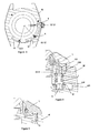
figure 3 est une vue en plan d'un boîtier pour la pièce d'horlogerie objet de l'invention avec coupe selon la ligne III-III de lafigure 4 ; - la
figure 4 est une vue en coupe selon la ligne IV-IV de lafigure 3 ; - la
figure 5 est une vue en coupe selon la ligne V-V de lafigure 3 ; - la
figure 6 est une vue en coupe du mécanisme de remontoir selon la ligne VI-VI de lafigure 3 , seule la tige de remontoir de ce mécanisme de remontoir étant visible sur lafigure 3 ; - la
figure 7 est une vue semblable à lafigure 6 montrant le mécanisme de remontoir dans une seconde position; - la
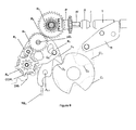
figure 8 est une vue en plan côté cadran de la pièce d'horlogerie, montrant l'ensemble du dispositif de réglage de fonctions et/ou d'indications horaires de la forme d'exécution préférée de la pièce d'horlogerie, en position de repos; - la
figure 9 est une vue partielle du dispositif de réglage de lafigure 8 , montrant ce dispositif en position de réglage des indications du quantième; - la
figure 10 est une vue partielle du dispositif de réglage de lafigure 8 , montrant ce dispositif en position de réglage des indications du jour de la semaine; - la
figure 11 est une vue partielle du dispositif de réglage de lafigure 8 , montrant ce dispositif en position de réglage de l'heure.
- The
Figures 1 and 2 are diagrams illustrating the operating principle of the adjustment device; - the
figure 3 is a plan view of a housing for the timepiece object of the invention with section along the line III-III of thefigure 4 ; - the
figure 4 is a sectional view along line IV-IV of thefigure 3 ; - the
figure 5 is a sectional view along line VV of thefigure 3 ; - the
figure 6 is a sectional view of the winding mechanism along line VI-VI of thefigure 3 , only the winding stem of this winding mechanism being visible on thefigure 3 ; - the
figure 7 is a view similar to thefigure 6 showing the winding mechanism in a second position; - the
figure 8 is a dial plan view of the timepiece, showing the entire function setting device and / or time indications of the preferred embodiment of the timepiece, in the rest position; - the
figure 9 is a partial view of the adjustment device of thefigure 8 , showing this device in the setting position of the date indications; - the
figure 10 is a partial view of the adjustment device of thefigure 8 , showing this device in the setting position of the indications of the day of the week; - the
figure 11 is a partial view of the adjustment device of thefigure 8 , showing this device in the time setting position.
Le concept général du dispositif de réglage est illustré de façon très schématique par les
Dans l'exemple considéré, le dispositif de réglage est prévu pour régler trois indications horaires différentes, chacune comprenant des moyens en appui contre la came C1 pour relier l'indication horaire à régler à un organe de réglage. Dans la représentation schématique des
Dans la forme d'exécution préférée de cette invention, il a été prévu d'utiliser comme organe de commande une tige de remontoir T à deux positions axiales, une position axiale poussée vers le mouvement de la pièce d'horlogerie, correspondant à la position traditionnelle de remontage du ressort de barillet dans le cas d'une pièce d'horlogerie mécanique et une position axiale où la tige T est tirée vers l'extérieur et correspondant traditionnellement à la position de mise à l'heure. Par contre dans le cas de la présente invention, cette seconde position correspond à une position de réglage de l'une des fonctions ou indications horaires sélectionnée ou à sélectionner.In the preferred embodiment of this invention, it has been proposed to use as a control member a winding stem T with two axial positions, an axial position pushed towards the movement of the timepiece, corresponding to the position traditional winding of the mainspring in the case of a mechanical timepiece and an axial position where the stem T is pulled outwards and traditionally corresponding to the time setting position. On the other hand, in the case of the present invention, this second position corresponds to a setting position of one of the functions or time indications selected or to be selected.
On décrira par la suite en détail le mécanisme de remontoir associé à la tige T. Pour l'instant, il suffit de préciser que cette tige T est en liaison desmodromique avec une seconde came C2 qui, dans cet exemple, est une came de forme générale circulaire et concentrique à la came de sélection C1. La liaison desmodromique entre la came C2 et la tige de remontoir T est réalisée par une tirette Ti montée pivotante autour d'un axe A4 et dont un bras est en prise avec la tige de remontoir T, tandis que l'autre bras porte une goupille montée avec jeu dans une ouverture allongée d'un bras C2' solidaire de la came C2.The winding mechanism associated with the rod T will now be described in detail. For the moment, it suffices to specify that this rod T is in desmodromic connection with a second cam C 2 which, in this example, is a cam of generally circular and concentric with the selection cam C 1 . The desmodromic link between the cam C 2 and the winding stem T is formed by a pull rod Ti pivotally mounted about an axis A 4 and one arm of which is engaged with the winding stem T, while the other arm carries a pin mounted with clearance in an elongate opening of an arm C 2 'integral with the cam C 2 .
Cette came C2 comporte n (n≥2) fois deux niveaux d'états 0 et 1, mais elle comporte ici autant d'états 1 formés par des creux qu'il n'y a de fonctions et/ou d'indications horaires à régler. Ces creux correspondant aux états 1 sont répartis à des distances angulaires les unes des autres correspondant aux distances angulaires respectives séparant les extrémités des leviers L1, L2, L3, en appui contre la came de sélection C1 et simultanément contre la came C2, les parties circulaires de ces deux cames correspondant aux états 0 étant de même rayon. Suivant la position axiale de la tige de remontoir T, la came C2 est donc susceptible d'occuper deux positions angulaires autour de l'axe de rotation des cames C1, C2, l'une correspondant à la tige de remontoir T en position axiale poussée, dans laquelle les creux des états 1 de la came C2 ne sont pas en face des extrémités des leviers respectifs L1, L2, L3, l'autre correspondant à la position de la tige de remontoir T en position tirée dans laquelle les creux des états 1 de la came C2 sont en face des extrémités respectives des leviers L1, L2, L3. Toutefois, étant donné que les leviers L1, L2, L3 appuient simultanément contre les deux cames C1, C2, cette seconde position angulaire de la came C2 n'est pas suffisante pour permettre d'effectuer un réglage d'une fonction ou d'une indication horaire. En effet, pour que ce réglage soit rendu possible, il faut que deux creux, correspondant à des états 1 des deux cames C1, C2, soient dans une position angulaire coïncidente et qu'ils soient en face de l'extrémité d'un des leviers L1, L2, L3. Ainsi, lorsque les creux des états 1 de la came C2 sont en face des extrémités des différents leviers L1, L2, L3, il suffit de faire tourner la came de sélection C1 pour amener son creux d'état 1 en face du levier L1, L2, L3, correspondant à la fonction ou l'indication horaire que l'on veut régler. Lors du passage de l'une à l'autre position de réglage, tous les leviers L1, L2, L3, passent par l'état 0.This cam C 2 has n (n≥2) times two levels of states 0 and 1, but here it has as many states 1 formed by valleys as there are functions and / or hourly indications. to settle. These hollows corresponding to the states 1 are distributed at angular distances from each other corresponding to the respective angular distances separating the ends of the levers L 1 , L 2 , L 3 , resting against the selection cam C 1 and simultaneously against the cam C 2 , the circular parts of these two cams corresponding to states 0 being of the same radius. According to the axial position of the winding stem T, the cam C 2 is thus capable of occupying two angular positions around the axis of rotation of the cams C 1 , C 2 , one corresponding to the winding stem T in pushed axial position, in which the recesses of the states 1 of the cam C 2 are not opposite the ends of the respective levers L 1 , L 2 , L 3 , the other corresponding to the position of the winding stem T in position drawn in which the hollow states 1 of the cam C 2 are opposite the respective ends of the levers L 1 , L 2 , L 3 . However, since the levers L 1 , L 2 , L 3 simultaneously support against the two cams C 1 , C 2 , this second angular position of the cam C 2 is not sufficient to allow adjustment to be made. a function or time indication. Indeed, for this adjustment to be made possible, it is necessary that two recesses, corresponding to states 1 of the two cams C 1 , C 2 , are in a coinciding angular position and that they face the end of one of the levers L 1 , L 2 , L 3 . Thus, when the recesses of the states 1 of the cam C 2 are in front of the ends of the various levers L 1 , L 2 , L 3 , it suffices to rotate the selection cam C 1 to bring its state hollow 1 into position. face of the lever L 1 , L 2 , L 3 , corresponding to the function or time indication that we want to adjust. When passing from one to the other adjustment position, all the levers L 1 , L 2 , L 3 , go through the state 0.
Le principe général du dispositif de réglage d'indications horaires ayant été décrit, on va maintenant décrire une forme d'exécution préférée de l'invention, dans laquelle la sélection de fonction ou d'indication à régler est réalisée par une lunette tournante L (
L'autre extrémité de l'arbre de commande A débouche dans une partie LM1 du logement LM de la carrure M qui s'ouvre dans la face latérale interne de la carrure M. Cette autre extrémité de l'arbre de commande A est solidaire d'un pignon muni de quatre bras D qui pénètrent tour à tour à l'intérieur de la carrure M pour entraîner les bras d'un sélecteur S (
On va maintenant décrire plus en détail le mécanisme de remontoir commandé par la tige de remontoir T et qui constitue aussi, dans cet exemple, l'organe de réglage, en se reportant plus particulièrement aux
La tige de remontoir T est en prise avec un bras de la tirette Ti, comme expliqué précédemment. Son extrémité interne présente une section III de forme polygonale complémentaire de celle de l'ouverture axiale d'un pignon de remontoir P de forme générale cylindrique dont une denture frontale Df engrène avec un renvoi R3 solidaire d'un renvoi R6 premier mobile du rouage de réglage. Le pignon de remontoir P comporte encore une denture d'angle Dc engrenant avec une denture d'angle d'une couronne de remontage RC1 munie d'une denture Breguet de chant Da en prise avec la denture Breguet de chant Da d'une seconde couronne de remontage RC2 solidaire d'un arbre de couronne AC et pressée axialement contre la première roue de couronne RC1 par un ressort RES1. Cette seconde couronne de remontage RC2 forme un mobile d'embrayage d'un mécanisme d'embrayage entre la tige de remontoir T et le train d'engrenage du remontoir.The winding stem T is engaged with an arm of the zipper Ti, as explained above. Its inner end has a section III of polygonal shape complementary to that of the axial opening of a winding pinion P of cylindrical general shape of which a front teeth D f meshes with a return R 3 integral with a reference R 6 first movable adjustment wheel. The winding pinion P further includes a corner tooth D c meshing with a toothing angle of a winding crown RC 1 provided with an edge toothing Breguet D into engagement with the edge D of Breguet toothing a second winding crown RC 2 secured to a crown shaft AC and axially pressed against the first crown wheel RC 1 by a spring RES 1 . This second winding crown RC 2 forms a clutch movable clutch mechanism between the winding stem T and the winding gear train.
Pour commander ce mécanisme d'embrayage, une extrémité de l'arbre de couronne AC est pressée par le ressort RES1 contre une première portion I de plus petit diamètre de la tige de remontoir T lorsque celle-ci est dans sa position poussée correspondant à sa position de remontage (
A noter que contrairement aux mécanismes de remontoir traditionnels, le pignon de remontoir P n'est pas coulissant, seule la tige de remontoir T coulisse à l'intérieur du pignon P qui est fixe par rapport à l'axe longitudinal de la tige de remontoir T. Ceci signifie que le premier mobile R3, R6 du rouage de réglage est constamment entraîné, quelle que soit la position axiale de la tige de remontoir T. Dans la position tirée de la tige de remontoir T (
Nous allons expliquer maintenant comment s'effectue la liaison cinématique entre la tige de remontoir T en position tirée illustrée par les
La
La bascule B2 porte quatre renvois, le renvoi R7 coaxial à l'axe de pivotement PB2, constamment en prise avec le renvoi R6 coaxial et solidaire du renvoi R3, le renvoi R8, engrenant avec le renvoi R7 et avec un renvoi R9, coaxial et solidaire d'un renvoi R10 et d'un organe correcteur de quantièmes COR1. Cet organe correcteur de quantièmes COR1 est destiné à venir en prise avec la denture interne d'un disque des quantièmes DIS dans une position de basculement de la bascule B2, tandis que le renvoi R10 est destiné à venir en prise dans une autre position de la bascule B2 avec un renvoi correcteur des jours de la semaine COR2 qui engrène avec une roue des jours Rj solidaire d'un disque portant les noms des jours J.The flip-flop B 2 carries four references, the reference R 7 coaxial with the pivot axis PB 2 , constantly in contact with the coaxial return R 6 and integral with the reference R 3 , the reference R 8 meshing with the reference R 7 and with a return R 9 , coaxial and integral with a reference R 10 and a date corrector COR 1 . This date corrector COR 1 is intended to come into engagement with the internal toothing of a date disk DIS in a tilting position of the flip-flop B 2 , while the return R 10 is intended to engage in another position of the flip-flop B 2 with a corrective reference of the days of the week COR 2 which meshes with a wheel of the days R j integral with a disc bearing the names of the days J.
La
La
La
Il est évident que le nombre de fonctions et/ou d'indications susceptibles d'être commandées à l'aide du dispositif de commande n'est pas limité à celui de l'exemple décrit. On pourrait ajouter d'autres réglages, le principe étant toujours celui d'une came de sélection à deux états 0, 1, susceptible d'être déplacée vis-à-vis des différents moyens agencés pour relier l'organe de réglage à l'indication horaire à régler lorsqu'un état 1 de la came est positionnée de manière à permettre à ces moyens de passer de leur état 0 à leur état 1.It is obvious that the number of functions and / or indications that can be controlled using the control device is not limited to that of the example described. Other adjustments could be added, the principle being always that of a two-state selection cam 0, 1, which can be displaced with respect to the various means arranged to connect the adjustment member to the time indication to be set when a state 1 of the cam is set to allow these means to go from their state 0 to their state 1.
Comme on a pu le constater lors de l'explication relative au principe de l'invention, la came C2 n'est nécessaire que dans la mesure où l'organe de commande est un organe à deux positions, comme dans l'exemple décrit où la tige de remontoir qui a normalement deux degrés de liberté, en rotation et en translation est utilisée à la fois comme organe de réglage dans son degré de liberté en rotation et comme organe de sélection dans son degré de liberté en translation axiale. Il faut alors une seconde came qui joue en quelque sorte le rôle d'un interrupteur mécanique. Si la came C2 est dans une position, aucun réglage n'est possible pour ne pas interférer avec l'autre fonction de la tige de remontoir T. Si la came C2 est dans son autre position, tous les réglages sont possibles, le sélecteur permettant de choisir parmi les réglages possibles, celui qui est désiré.As can be seen in the explanation of the principle of the invention, the cam C 2 is necessary only to the extent that the control member is a two-position member, as in the example described where the winding stem which normally has two degrees of freedom, in rotation and in translation is used both as a control member in its degree of freedom in rotation and as selection member in its degree of freedom in axial translation. It then takes a second cam that plays somehow the role of a mechanical switch. If the cam C 2 is in a position, no adjustment is possible to avoid interfering with the other function of the winding stem T. If the cam C 2 is in its other position, all settings are possible, the selector to choose from the possible settings, the one that is desired.
Ainsi, on pourrait avoir la seule came de sélection C1 et deux organes distincts, l'un pour le remontage exclusivement, l'autre pour le réglage de l'indication horaire sélectionnée. Si ces organes sont deux tiges, celles-ci n'auraient qu'une position axiale et le mécanisme de débrayage des couronnes de remontage RC1, RC2 pourrait être supprimé. Ces deux tiges pourraient être soit séparées par un angle autour de la carrure M, soit aussi être montées coaxialement l'une à l'autre et chacune fixée à un bouton d'entraînement connu sous le nom de couronne de remontoir, les deux couronnes étant adjacentes l'une à l'autre le long de l'axe des tiges de remontoir et de réglage.Thus, one could have the single selection cam C 1 and two separate organs, one for winding exclusively, the other for setting the selected time indication. If these members are two rods, they would have an axial position and the disengagement mechanism winding crowns RC 1 , RC 2 could be removed. These two rods could be either separated by an angle around the middle part M, or also be mounted coaxially to each other and each attached to a drive button known as the winding crown, the two crowns being adjacent to each other along the axis of the winding and adjusting rods.
Il serait aussi possible dans le cas d'un dispositif de commande avec une seule came de sélection C1, de n'avoir qu'un seul organe de commande, par exemple une tige du type tige de remontoir à une seule position axiale. Dans ce cas, le remontage correspondrait à une des fonctions sélectionnée par la came de sélection C1.It would also be possible in the case of a control device with a single selection cam C 1 , to have only one control member, for example a stem of the winding stem type at a single axial position. In this case, the reassembly would correspond to one of the functions selected by the selection cam C 1 .
Bien que l'on ait illustré l'utilisation d'une lunette tournante pour commander la came de sélection C1, rien n'empêcherait d'utiliser une tige du type de la tige de remontoir pour effectuer la commande de cette came de sélection.Although we have illustrated the use of a rotating bezel to control the selection cam C 1 , nothing would prevent the use of a stem of the type of the winding stem to control the selection cam.
D'autres modifications pourraient être imaginées. De même, on peut envisager tous les types de fonctions et/ou d'indications horaires susceptibles d'être réglés grâce au dispositif de réglage de la pièce d'horlogerie objet de l'invention. C'est ainsi que l'on pourrait régler de la même manière les changements de fuseaux horaires.Other modifications could be imagined. Similarly, one can consider all types of functions and / or time indications that can be adjusted through the adjustment device of the timepiece object of the invention. This is how one could adjust the time zone changes in the same way.
Il est par ailleurs évident de la description qui précède que la pièce d'horlogerie selon l'invention peut être aussi bien mécanique qu'électronique.It is also clear from the foregoing description that the timepiece according to the invention can be both mechanical and electronic.
Claims (9)
Priority Applications (1)
| Application Number | Priority Date | Filing Date | Title |
|---|---|---|---|
| EP12182768.7A EP2533110B1 (en) | 2007-07-02 | 2008-06-26 | Timepiece provided with a device for the control of functions and/or time indications |
Applications Claiming Priority (3)
| Application Number | Priority Date | Filing Date | Title |
|---|---|---|---|
| EP07405188 | 2007-07-02 | ||
| EP08405164.8A EP2012199B9 (en) | 2007-07-02 | 2008-06-26 | Timepiece fitted with a device for the control of functions and/or time indications |
| EP12182768.7A EP2533110B1 (en) | 2007-07-02 | 2008-06-26 | Timepiece provided with a device for the control of functions and/or time indications |
Related Parent Applications (3)
| Application Number | Title | Priority Date | Filing Date |
|---|---|---|---|
| EP08405164.8 Division | 2008-06-26 | ||
| EP08405164.8A Division-Into EP2012199B9 (en) | 2007-07-02 | 2008-06-26 | Timepiece fitted with a device for the control of functions and/or time indications |
| EP08405164.8A Division EP2012199B9 (en) | 2007-07-02 | 2008-06-26 | Timepiece fitted with a device for the control of functions and/or time indications |
Publications (3)
| Publication Number | Publication Date |
|---|---|
| EP2533110A2 true EP2533110A2 (en) | 2012-12-12 |
| EP2533110A3 EP2533110A3 (en) | 2017-09-27 |
| EP2533110B1 EP2533110B1 (en) | 2018-10-24 |
Family
ID=39204998
Family Applications (2)
| Application Number | Title | Priority Date | Filing Date |
|---|---|---|---|
| EP08405164.8A Active EP2012199B9 (en) | 2007-07-02 | 2008-06-26 | Timepiece fitted with a device for the control of functions and/or time indications |
| EP12182768.7A Active EP2533110B1 (en) | 2007-07-02 | 2008-06-26 | Timepiece provided with a device for the control of functions and/or time indications |
Family Applications Before (1)
| Application Number | Title | Priority Date | Filing Date |
|---|---|---|---|
| EP08405164.8A Active EP2012199B9 (en) | 2007-07-02 | 2008-06-26 | Timepiece fitted with a device for the control of functions and/or time indications |
Country Status (4)
| Country | Link |
|---|---|
| US (2) | US7980756B2 (en) |
| EP (2) | EP2012199B9 (en) |
| JP (1) | JP5555412B2 (en) |
| DE (1) | DE08405164T1 (en) |
Families Citing this family (17)
| Publication number | Priority date | Publication date | Assignee | Title |
|---|---|---|---|---|
| EP2124112A1 (en) * | 2008-05-22 | 2009-11-25 | CT Time S.A. | Timepiece mechanism and module comprising such a mechanism |
| EP2367080B1 (en) * | 2010-03-17 | 2019-01-16 | Glashütter Uhrenbetrieb GmbH | Device for controlling and adjusting a timepiece movement |
| EP2453322B1 (en) * | 2010-11-16 | 2013-07-17 | Omega SA | Fast time quantity indicator corrector for a timepiece |
| EP2523054A1 (en) * | 2011-05-12 | 2012-11-14 | Manufacture La Joux-Perret SA | Timepiece |
| WO2012175595A1 (en) | 2011-06-21 | 2012-12-27 | Rolex S.A. | Timepiece comprising a winding mechanism and at least one mechanism for correcting at least one indicator member |
| EP2565728B1 (en) * | 2011-08-29 | 2018-05-09 | ETA SA Manufacture Horlogère Suisse | Independent control mechanism for a timepiece |
| EP3499319A3 (en) | 2012-08-21 | 2019-07-17 | Rolex Sa | Clutch lever and clutch device for a clockwork mechanism |
| CH707870B1 (en) * | 2013-04-08 | 2017-07-14 | Gfpi S A | Mechanism for selecting and operating the functions of a watch movement and a timepiece comprising such a mechanism. |
| JP6741397B2 (en) | 2014-02-10 | 2020-08-19 | ロレックス・ソシエテ・アノニムRolex Sa | Mobile watch side and watch |
| EP3143463B1 (en) * | 2014-05-14 | 2018-10-10 | ETA SA Manufacture Horlogère Suisse | Quick correction mechanism of a timepiece |
| EP3026506B1 (en) * | 2014-11-26 | 2019-01-16 | The Swatch Group Management Services AG | Timer with speed selector |
| JP6908761B2 (en) * | 2015-04-01 | 2021-07-28 | ロレックス・ソシエテ・アノニムRolex Sa | A mechanism for winding and / or correcting at least one watch function, and a device for selecting the watch function. |
| JP6728215B2 (en) * | 2015-04-01 | 2020-07-22 | ロレックス・ソシエテ・アノニムRolex Sa | Mechanism for winding and/or modifying at least one timepiece function and a device for selecting the timepiece function |
| CH712662A1 (en) * | 2016-07-12 | 2018-01-15 | Bremont Watch Company | Mechanism for selecting and operating functions of a watch movement. |
| CH713604A1 (en) | 2017-03-22 | 2018-09-28 | Sa De La Manufacture Dhorlogerie Audemars Piguet & Cie | Selection and actuation mechanism as well as a device for adjusting the functions of a timepiece. |
| CH714741B1 (en) * | 2018-03-12 | 2022-06-30 | Hublot Sa Geneve | Locking system for a watch barrel ratchet. |
| CH719985A1 (en) * | 2022-08-24 | 2024-02-29 | Van Cleef & Arpels SA | Device for coordinated actuation of two mechanisms of a timepiece |
Citations (4)
| Publication number | Priority date | Publication date | Assignee | Title |
|---|---|---|---|---|
| US360415A (en) | 1887-04-05 | Ferson byam | ||
| US4253177A (en) | 1978-12-14 | 1981-02-24 | Diehl Gmbh & Co. | Apparatus for manual adjustment of a clock |
| JPH0236395A (en) | 1988-07-26 | 1990-02-06 | Citizen Watch Co Ltd | Electronic wrist watch with rotary bezel |
| EP1584000A2 (en) | 2002-12-06 | 2005-10-12 | Powermike.com LP | World timepiece |
Family Cites Families (14)
| Publication number | Priority date | Publication date | Assignee | Title |
|---|---|---|---|---|
| US444511A (en) | 1891-01-13 | Wrench | ||
| CH185971A4 (en) * | 1971-02-08 | 1972-09-15 | ||
| JPS5733384A (en) * | 1980-08-07 | 1982-02-23 | Seiko Koki Kk | Mode switching device of electronic timepiece |
| US5339297A (en) * | 1989-06-19 | 1994-08-16 | Seiko Epson Corporation | Switching arrangement for applying battery voltage to circuitry block in an analog timepiece |
| US5251533A (en) * | 1992-06-08 | 1993-10-12 | Mark Layton | Firing mode selection apparatus |
| JP3191035B2 (en) * | 1995-03-01 | 2001-07-23 | セイコークロック株式会社 | Clock machine body for daylight saving time |
| KR100337359B1 (en) * | 1999-12-15 | 2002-05-21 | 이계안 | Method and “d”range back drive holding system for vehicle |
| US20030015198A1 (en) * | 2001-06-18 | 2003-01-23 | Heeke David W. | Method and device for addressing sleep apnea and related breathing disorders |
| EP1336907A2 (en) * | 2002-02-14 | 2003-08-20 | Richemont International S.A. | Actuating mechanism for time setting device of a timepiece and timepiece incorporating such a mechanism |
| TW200413485A (en) * | 2002-07-26 | 2004-08-01 | Orient Chemical Ind | Solid pigment composition for pigment ink, pigment ink containing the same, and process for preparing these |
| JP4658547B2 (en) * | 2004-09-13 | 2011-03-23 | シチズンホールディングス株式会社 | Electronic clock with chronograph function |
| CH699146B1 (en) * | 2004-10-08 | 2010-01-29 | Artisans Boitiers Sa | Control device for watch. |
| CH705439B1 (en) * | 2006-12-18 | 2013-03-15 | Jean Pierre Jaquet | An operating mechanism of a chronograph. |
| EP1939699B1 (en) * | 2006-12-29 | 2012-05-30 | Montres Breguet S.A. | Multifunctional coaxial corrector device |
-
2008
- 2008-06-26 EP EP08405164.8A patent/EP2012199B9/en active Active
- 2008-06-26 DE DE08405164T patent/DE08405164T1/en active Pending
- 2008-06-26 EP EP12182768.7A patent/EP2533110B1/en active Active
- 2008-06-30 US US12/164,885 patent/US7980756B2/en active Active
- 2008-07-01 JP JP2008172775A patent/JP5555412B2/en active Active
-
2011
- 2011-06-13 US US13/159,082 patent/US8328414B2/en active Active
Patent Citations (4)
| Publication number | Priority date | Publication date | Assignee | Title |
|---|---|---|---|---|
| US360415A (en) | 1887-04-05 | Ferson byam | ||
| US4253177A (en) | 1978-12-14 | 1981-02-24 | Diehl Gmbh & Co. | Apparatus for manual adjustment of a clock |
| JPH0236395A (en) | 1988-07-26 | 1990-02-06 | Citizen Watch Co Ltd | Electronic wrist watch with rotary bezel |
| EP1584000A2 (en) | 2002-12-06 | 2005-10-12 | Powermike.com LP | World timepiece |
Also Published As
| Publication number | Publication date |
|---|---|
| JP5555412B2 (en) | 2014-07-23 |
| EP2012199B9 (en) | 2019-02-13 |
| US20110242947A1 (en) | 2011-10-06 |
| JP2009014722A (en) | 2009-01-22 |
| DE08405164T1 (en) | 2009-09-24 |
| US8328414B2 (en) | 2012-12-11 |
| EP2533110B1 (en) | 2018-10-24 |
| US7980756B2 (en) | 2011-07-19 |
| EP2012199B1 (en) | 2012-10-10 |
| EP2012199A3 (en) | 2011-07-27 |
| EP2012199B2 (en) | 2017-10-25 |
| EP2533110A3 (en) | 2017-09-27 |
| EP2012199A2 (en) | 2009-01-07 |
| US20090010109A1 (en) | 2009-01-08 |
Similar Documents
| Publication | Publication Date | Title |
|---|---|---|
| EP2533110B1 (en) | Timepiece provided with a device for the control of functions and/or time indications | |
| EP1918792B1 (en) | Timepiece including a correction mechanism for a device displaying a time quantity | |
| EP2724199B1 (en) | Timepiece comprising a winding mechanism and at least one mechanism for correcting at least one indicator member | |
| EP2945026B1 (en) | Quick correction mechanism of a timepiece | |
| EP2701014A1 (en) | Clutch lever and clutch device for a clockwork mechanism | |
| WO2004031869A2 (en) | Mechanical hour and minute display device | |
| EP3144743B1 (en) | Clock movement comprising a mechanism for correcting the date | |
| EP1862871B1 (en) | Timepiece comprising an improved time-setting mechanism | |
| EP3008523B1 (en) | Calendar mechanism for a clock movement | |
| EP1152303A1 (en) | Timepiece with winding mechanism and mechanism for the correction of at least two indicating organs | |
| WO2008046917A2 (en) | Indicator hand for a timepiece, movement for driving such an indicator hand and related timepiece | |
| CH702548B1 (en) | function selection mechanism for timepiece movement comprising at least one complication. | |
| EP0008832B1 (en) | Clockwork with hands comprising a differential-gear mechanism | |
| CH710118A2 (en) | Corps gear, adjusting mechanism of a time difference, clock movement, and timepiece. | |
| EP3278183A1 (en) | Mechanism for rewinding and/or correcting at least one clock function and device for selecting a clock function | |
| EP3602202B1 (en) | Device for adjusting functions of a timepiece | |
| EP2957964B1 (en) | Tilting coupling device for timepiece | |
| EP2455823B1 (en) | Timepiece with universal time display | |
| EP0479147B1 (en) | Mechanical and/or electromechanical timepiece | |
| EP3857313B1 (en) | Display mechanism with a single dial window | |
| EP3904962B1 (en) | Device for indexing and device for displaying a time or time-derived indication | |
| EP4012505A1 (en) | Timepiece device with anti-blocking mobile | |
| EP4148504A1 (en) | Time zone correction mechanism for a timepiece | |
| CH718954A2 (en) | Time zone correction mechanism for a timepiece. | |
| CH713331A2 (en) | Timepiece having a day / night display taking into account seasonal variations. |
Legal Events
| Date | Code | Title | Description |
|---|---|---|---|
| PUAI | Public reference made under article 153(3) epc to a published international application that has entered the european phase |
Free format text: ORIGINAL CODE: 0009012 |
|
| AC | Divisional application: reference to earlier application |
Ref document number: 2012199 Country of ref document: EP Kind code of ref document: P |
|
| AK | Designated contracting states |
Kind code of ref document: A2 Designated state(s): CH DE FR GB LI |
|
| AX | Request for extension of the european patent |
Extension state: AL BA MK RS |
|
| RIN1 | Information on inventor provided before grant (corrected) |
Inventor name: GRAEMIGER, PIERRE-ALAIN Inventor name: ROSENZWEIG, ARNAUD |
|
| PUAL | Search report despatched |
Free format text: ORIGINAL CODE: 0009013 |
|
| AK | Designated contracting states |
Kind code of ref document: A3 Designated state(s): CH DE FR GB LI |
|
| AX | Request for extension of the european patent |
Extension state: AL BA MK RS |
|
| RIC1 | Information provided on ipc code assigned before grant |
Ipc: G04B 27/06 20060101AFI20170823BHEP |
|
| STAA | Information on the status of an ep patent application or granted ep patent |
Free format text: STATUS: REQUEST FOR EXAMINATION WAS MADE |
|
| 17P | Request for examination filed |
Effective date: 20180327 |
|
| GRAP | Despatch of communication of intention to grant a patent |
Free format text: ORIGINAL CODE: EPIDOSNIGR1 |
|
| RBV | Designated contracting states (corrected) |
Designated state(s): CH DE FR GB LI |
|
| STAA | Information on the status of an ep patent application or granted ep patent |
Free format text: STATUS: GRANT OF PATENT IS INTENDED |
|
| INTG | Intention to grant announced |
Effective date: 20180503 |
|
| GRAS | Grant fee paid |
Free format text: ORIGINAL CODE: EPIDOSNIGR3 |
|
| GRAA | (expected) grant |
Free format text: ORIGINAL CODE: 0009210 |
|
| STAA | Information on the status of an ep patent application or granted ep patent |
Free format text: STATUS: THE PATENT HAS BEEN GRANTED |
|
| AC | Divisional application: reference to earlier application |
Ref document number: 2012199 Country of ref document: EP Kind code of ref document: P |
|
| AK | Designated contracting states |
Kind code of ref document: B1 Designated state(s): CH DE FR GB LI |
|
| REG | Reference to a national code |
Ref country code: GB Ref legal event code: FG4D Free format text: NOT ENGLISH |
|
| REG | Reference to a national code |
Ref country code: CH Ref legal event code: EP |
|
| REG | Reference to a national code |
Ref country code: DE Ref legal event code: R096 Ref document number: 602008057620 Country of ref document: DE |
|
| REG | Reference to a national code |
Ref country code: CH Ref legal event code: NV Representative=s name: MOINAS AND SAVOYE SARL, CH |
|
| REG | Reference to a national code |
Ref country code: DE Ref legal event code: R097 Ref document number: 602008057620 Country of ref document: DE |
|
| PLBE | No opposition filed within time limit |
Free format text: ORIGINAL CODE: 0009261 |
|
| STAA | Information on the status of an ep patent application or granted ep patent |
Free format text: STATUS: NO OPPOSITION FILED WITHIN TIME LIMIT |
|
| 26N | No opposition filed |
Effective date: 20190725 |
|
| P01 | Opt-out of the competence of the unified patent court (upc) registered |
Effective date: 20230528 |
|
| PGFP | Annual fee paid to national office [announced via postgrant information from national office to epo] |
Ref country code: FR Payment date: 20230622 Year of fee payment: 16 Ref country code: DE Payment date: 20230613 Year of fee payment: 16 |
|
| PGFP | Annual fee paid to national office [announced via postgrant information from national office to epo] |
Ref country code: GB Payment date: 20230620 Year of fee payment: 16 Ref country code: CH Payment date: 20230702 Year of fee payment: 16 |