EP2532813B1 - Zahnstange - Google Patents
Zahnstange Download PDFInfo
- Publication number
- EP2532813B1 EP2532813B1 EP11169100.2A EP11169100A EP2532813B1 EP 2532813 B1 EP2532813 B1 EP 2532813B1 EP 11169100 A EP11169100 A EP 11169100A EP 2532813 B1 EP2532813 B1 EP 2532813B1
- Authority
- EP
- European Patent Office
- Prior art keywords
- toothed rack
- rack
- coupling means
- drive
- slider
- Prior art date
- Legal status (The legal status is an assumption and is not a legal conclusion. Google has not performed a legal analysis and makes no representation as to the accuracy of the status listed.)
- Not-in-force
Links
- 230000008878 coupling Effects 0.000 claims description 69
- 238000010168 coupling process Methods 0.000 claims description 69
- 238000005859 coupling reaction Methods 0.000 claims description 69
- 238000004519 manufacturing process Methods 0.000 claims description 5
- 238000000034 method Methods 0.000 claims 1
- 238000004080 punching Methods 0.000 claims 1
- 239000002184 metal Substances 0.000 description 4
- 230000005540 biological transmission Effects 0.000 description 2
- 238000006073 displacement reaction Methods 0.000 description 2
- 208000027418 Wounds and injury Diseases 0.000 description 1
- 238000005520 cutting process Methods 0.000 description 1
- 230000006378 damage Effects 0.000 description 1
- 230000007423 decrease Effects 0.000 description 1
- 238000004049 embossing Methods 0.000 description 1
- 239000005357 flat glass Substances 0.000 description 1
- 208000014674 injury Diseases 0.000 description 1
- 238000003780 insertion Methods 0.000 description 1
- 230000037431 insertion Effects 0.000 description 1
- 239000002023 wood Substances 0.000 description 1
Images


Classifications
-
- E—FIXED CONSTRUCTIONS
- E05—LOCKS; KEYS; WINDOW OR DOOR FITTINGS; SAFES
- E05B—LOCKS; ACCESSORIES THEREFOR; HANDCUFFS
- E05B63/00—Locks or fastenings with special structural characteristics
- E05B63/0056—Locks with adjustable or exchangeable lock parts
-
- E—FIXED CONSTRUCTIONS
- E05—LOCKS; KEYS; WINDOW OR DOOR FITTINGS; SAFES
- E05C—BOLTS OR FASTENING DEVICES FOR WINGS, SPECIALLY FOR DOORS OR WINDOWS
- E05C9/00—Arrangements of simultaneously actuated bolts or other securing devices at well-separated positions on the same wing
- E05C9/02—Arrangements of simultaneously actuated bolts or other securing devices at well-separated positions on the same wing with one sliding bar for fastening when moved in one direction and unfastening when moved in opposite direction; with two sliding bars moved in the same direction when fastening or unfastening
- E05C9/021—Arrangements of simultaneously actuated bolts or other securing devices at well-separated positions on the same wing with one sliding bar for fastening when moved in one direction and unfastening when moved in opposite direction; with two sliding bars moved in the same direction when fastening or unfastening with rack and pinion mechanism
Definitions
- the invention relates to a rack for a drive rod fitting which has at least on its upper side a plurality of drive recesses for engagement of a drive pinion.
- a drive rod of the espagnolette fitting is displaced by a drive pinion, which engages in drive recesses of the drive rod.
- the drive pinion is rotated via a mandrel, which is connected, for example, with an actuating element, such as a handle.
- the measure between the pivot point of the drive pinion and the underside of the drive rod is referred to as a backset.
- the backset is typically between 11 mm and 15 mm. The backset is so far specified for each espagnolette fitting. If a different backset on one wing is desired, then another can not be another Drive pinion can be used with a different diameter.
- a transmission for espagnolettes with a gear arranged in a housing is known, which is in engagement with a driver in the form of a plate-shaped rack which protrudes in its plane through a longitudinal slot of the housing and is connected to a one-piece drive rod.
- the rack is formed by non-cutting deformation of a metal plate, which extended from the plane of the metal plate teeth extend at least over part of the surface of the metal plate, wherein the housing of one of the shape of the pinion and Rack-adapted housing part and an approximately quadrangular plate is provided, in which the screw holes are provided for attachment in the laterally over the adapted housing part projecting portions of the plate, and wherein the width of the longitudinal slot in the housing corresponds to the width of the metal plate intended for the rack.
- the WO 2008/088157 A1 discloses a casement window comprising a window frame attached to a building and a casement frame suspended from the window frame and provided with window glass , wherein the casement window comprises a corner hinge assembly mounted in a corner of the casement frame at a location corresponding to the hinge, a coupling unit attached to the window frame and having a coupling member connected to the corner hinge assembly to keep the corner joint assembly rotatable.
- a handle unit which restricts the rotation of the coupling member connected to the corner joint assembly according to an operation of a handle, thereby detecting the coupling unit, the corner joint structure on the coupling unit being detected in a state where the sash frame is rotated with respect to the window frame , whereby the sash frame is kept open.
- the invention is therefore based on the object to provide a device with which different backset dimensions can be realized when using the same drive rod and the same drive pinion.
- a rack for a espagnolette which has at least on its upper side a plurality of drive recesses for engaging a drive pinion, wherein the rack at its top side opposite the underside at least a first coupling means for coupling the rack with a drive rod of the espagnolette or a has another rack.
- the toothed rack can be arranged on the drive rod by the first coupling means.
- the drive pinion then no longer engages in the drive recesses of the drive rod but in the drive recesses of the rack. If a smaller backset is desired, the rack between the drive pinion and the drive rod can be removed again.
- the rack has on its upper side at least a second coupling means for coupling with another rack on the top of the rack.
- a second coupling means for coupling with another rack on the top of the rack.
- the first and / or second coupling means may be formed as a recess or projection.
- Recesses and projections can be particularly simple and inexpensive, e.g. by embossing, are made.
- At least one projection and / or at least one recess preferably have a round cross-section. Round projections and recesses can be made very easy. Furthermore, by avoiding sharp edges, the risk of injury to the user when handling the rack decreases.
- the first coupling means and the second coupling means are coordinated.
- the first coupling means and the second coupling means are preferably arranged opposite one another.
- the individual racks can thereby be arranged in any order to each other.
- coupling means in the form of recesses and projections are used, they are preferably arranged such that at least one recess provided on the upper side, or at least one projection provided on the upper side with a projection provided on the underside of the rack, or one on the underside of the rack provided recess, aligned.
- the rack is preferably via the first and / or second coupling means positively and / or non-positively connected to a further rack.
- the racks can be arranged so free of play to each other.
- the arranged on the drive rod rack is arranged without play on the drive rod. An actuation of the actuating element and thus of the drive pinion can be transmitted directly to the locking elements.
- the rack preferably has two first and second coupling means. By the two “coupling means pairs" several racks can be arranged rotationally fixed to each other.
- the first and second coupling means may be provided in the region of the longitudinal ends of the rack.
- racks are so particularly rotatable to each other can be arranged.
- end-side arrangement of the coupling means remains space for the drive recesses in the central region of the rack.
- the coupling means may be provided symmetrically to the central, perpendicular to the top of the rack extending symmetry axis.
- the coupling means may be provided symmetrically to this axis of symmetry.
- the rack can be rotated about this axis of symmetry, without changing the arrangement possibility of the other rack (s) or the drive rod, changed. Therefore, when the rack is arranged, the user does not need to pay any attention to the orientation of the rack around this axis of symmetry.
- the rack may extend both along a first longitudinal direction Driving rod as well as rotated by 180 ° to be arranged. The arrangement of the rack is thereby particularly simple.
- the top and bottom of the rack are preferably flat except for the coupling means and the drive recesses. As a result, several racks can be stacked form-fitting.
- the rack is integrally formed. This results in particularly low production costs for the rack.
- the invention further relates to a method for producing a previously described rack, in which at least one recess is embossed in an upper side or underside of the rack such that a projection aligned with the recess is formed on the opposite upper side or lower side.
- Recess and projection can be produced with a single manufacturing step.
- all recesses or recesses and drive recesses of the rack are produced in a single manufacturing step.
- the rack is so particularly inexpensive to produce.
- the invention further relates to a drive rod fitting, with a provided with at least one rack coupling means drive rod and at least one rack previously described.
- the drive rod of the espagnolette preferably has two rack coupling means for coupling to a rack.
- the rack in particular play, be connected to the drive rod.
- the drive rod may have at its, the rack-facing top, drive recesses to be used without a rack can.
- At least two racks are provided, each with different heights.
- the height of a single rack is preferably chosen smaller than 3 mm. The user can thus realize in a simple manner by means of a combination of one or more racks a desired backset.
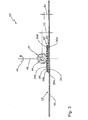
- FIG. 1 illustrates an espagnolette 10 according to the invention for actuating locking elements of a door leaf (not shown).
- the espagnolette fitting 10 has a drive rod 12 and a Drive housing 14 on.
- the drive housing 14 comprises two drive housing shells 14a, 14b.
- the drive housing shells 14a, 14b respectively have guide projections 16a, 16b which engage behind the drive rod 12 in order to guide the drive rod 12 in the drive housing 14.
- the espagnolette fitting 10 furthermore has a drive pinion 18.
- the drive pinion 18 is guided in recesses, not shown, of the drive housing shells 14a, 14b.
- the drive pinion 18 has a substantially square edged mandrel recess 20 for a with a actuating element (not shown) coupled in cross-section rectangular mandrel.
- the mandrel recess 20 represents the axis of rotation of the drive pinion 18. An actuation of the actuating element coupled to a mandrel therefore leads to a rotation of the
- the rotation of the drive pinion 18 leads to a displacement of a first rack 22 according to the invention.
- the first rack 22 has a plurality of drive recesses, of which, for reasons of clarity, only a first drive recess 24a is provided with a reference numeral.
- the drive pinion 18 has a plurality of unspecified teeth for displacement of the first rack 22, which engage in the drive recesses of the first rack 22.
- a movement of the first rack 22 is transmitted to a second rack 26, which is identical to the first rack 22 formed. From the second rack 26, the movement is further transmitted to the drive rod 12.
- the drive rod 12 itself has drive recesses, of which, for reasons of clarity, only a first drive recess 27a is provided with a reference numeral.
- the drive pinion 18 could therefore, when using a corresponding housing, engage directly in the drive recesses of the drive rod 12.
- FIG. 2 shows the drive pinion 18 with drive pinion projections 28a, 28b, which engage in corresponding recesses of the FIG. 2
- Drive housing shells not shown can be used.
- the first rack 22 is shown partially cut.
- a first coupling means 30a designed in the form of a round projection can be seen.
- the first coupling means 30 a is formed on the underside 32 of the first rack 22.
- a second coupling means 36a is formed in the form of a round recess or depression.
- the first coupling means 30a has the shape of a protrusion with a round diameter.
- the first coupling means 30a is inserted in a second coupling means 38a of the second rack 26.
- a first coupling means 40a of the second rack 26 is in turn inserted into a first rack coupling means 42a of the drive rod 12.
- the coupling means 30a, 40a designed as projections here are aligned with the coupling means 36a, 38a, 42a which are designed as recesses.
- the diameters of the coupling means 30a, 36a, 38a, 40a, 42a are further adapted to each other such that an interference fit between the first rack 22, the second rack 26 and the drive rod 12 is formed.
- the first rack 22 can thereby be attached to the second rack 26.
- the second rack 26 can be plugged onto the drive rod 12. A tool for fixed arrangement of the first rack 22 on the second rack 26 and this on the drive rod 12 is therefore not needed.
- the first rack 22 and the second rack 26 can be removed without tools from the
- FIG. 3 shows a second drive rod fitting 10 'according to the invention with a drive pinion 18', whose movement is transmitted to a drive rod 12 '.
- a drive pinion 18' To move the drive pinion 18 ', this is rotated about an axis of rotation 44 by means of an actuating element, not shown.
- the first rack 22 ' has first coupling means 30a', 30b and second coupling means 36a ', 36b.
- the first coupling means 30a ', 30b are formed as projections with a round cross-section.
- the second coupling means 36a ', 36b are formed as recesses with a round cross-section.
- the first coupling means 30a ', 30b are provided symmetrically to a central axis of symmetry 46 extending perpendicularly to an upper side 34' of the first rack 22 '.
- the second coupling means 36a ', 36b are formed symmetrically to the axis 46.
- the first rack 22 'can thus also, as indicated by an arrow 48, are used rotated by 180 °.
- the first rack 22 ' has a plurality of drive recesses, of which, for reasons of clarity, only a first drive recess 24a' is provided with a reference numeral.
- the upper side 34 ' is flat except for the drive recesses and the second coupling means 36a', 36b.
- a bottom 32 'of the first rack 22' is flat except for the first coupling means 30a ', 30b.
- the second rack 26 ' is identical to the first rack 22' is formed. Due to the essentially flat training of the first Rack 22 'and the second rack 26' they can be easily stacked one above the other. Furthermore, the second rack 26 'can be easily placed on the drive rod 12'.
- the coupling means 30a ', 30b, 36a', 36b are coordinated so that a plurality of racks 22 ', 26' can be positively inserted into one another.
- the distance between the pivot point 44 of the drive pinion 18 'and a bottom 50 of the drive rod 12' is referred to as a backset in the context of the invention.
- the backset according to the arrangement of the espagnolette 10 'is designated by a first dimension 52. If the espagnolette fitting 10 'is now inserted on another wing (not shown) having a smaller backset, the first rack 22' and / or the second rack 26 'can be removed from the espagnolette fitting 10'.
- the drive pinion 18 'can now be arranged closer to the drive rod 12', resulting in a smaller backset.
- the at a removal of the first rack 22 'and the second rack 26' resulting backset is in Fig. 3 represented by a second dimension 54.
Landscapes
- Engineering & Computer Science (AREA)
- Structural Engineering (AREA)
- Mechanical Engineering (AREA)
- Transmission Devices (AREA)
- Labeling Devices (AREA)
Priority Applications (4)
| Application Number | Priority Date | Filing Date | Title |
|---|---|---|---|
| EP11169100.2A EP2532813B1 (de) | 2011-06-08 | 2011-06-08 | Zahnstange |
| PL11169100T PL2532813T3 (pl) | 2011-06-08 | 2011-06-08 | Listwa zębata |
| SI201130274T SI2532813T1 (sl) | 2011-06-08 | 2011-06-08 | Zobata letev |
| CN201210188554.XA CN102817993B (zh) | 2011-06-08 | 2012-06-08 | 齿条 |
Applications Claiming Priority (1)
| Application Number | Priority Date | Filing Date | Title |
|---|---|---|---|
| EP11169100.2A EP2532813B1 (de) | 2011-06-08 | 2011-06-08 | Zahnstange |
Publications (2)
| Publication Number | Publication Date |
|---|---|
| EP2532813A1 EP2532813A1 (de) | 2012-12-12 |
| EP2532813B1 true EP2532813B1 (de) | 2014-09-10 |
Family
ID=44907671
Family Applications (1)
| Application Number | Title | Priority Date | Filing Date |
|---|---|---|---|
| EP11169100.2A Not-in-force EP2532813B1 (de) | 2011-06-08 | 2011-06-08 | Zahnstange |
Country Status (4)
| Country | Link |
|---|---|
| EP (1) | EP2532813B1 (pl) |
| CN (1) | CN102817993B (pl) |
| PL (1) | PL2532813T3 (pl) |
| SI (1) | SI2532813T1 (pl) |
Families Citing this family (2)
| Publication number | Priority date | Publication date | Assignee | Title |
|---|---|---|---|---|
| GB2588900B (en) * | 2019-11-12 | 2023-08-16 | Gretsch Unitas Ltd | A latching mechanism |
| GB2602145A (en) * | 2020-12-21 | 2022-06-22 | Assa Abloy Ltd | Multi-point lock |
Family Cites Families (6)
| Publication number | Priority date | Publication date | Assignee | Title |
|---|---|---|---|---|
| DE1284871B (de) * | 1962-07-26 | 1968-12-05 | Jaeger Kg Frank | Getriebe fuer Treibstangenverschluesse od. dgl. |
| DE2115744A1 (de) * | 1971-03-31 | 1972-10-12 | Siegenia-Frank KG, 5900 Siegen-Kaan-Marienborn | Kantengetriebe als Treibstangenbeschlag für Fenster, Türen od. dgl |
| US5642909A (en) * | 1996-03-01 | 1997-07-01 | Federal-Hoffman, Inc. | Latch system |
| KR101056704B1 (ko) * | 2007-01-17 | 2011-08-12 | (주)엘지하우시스 | 슬라이딩 바아의 이동에 의한 랙 기어 운동 단속 장치 및이를 이용한 임의 각도에서 잠금이 가능한 턴 방식의 창호개폐장치 |
| CN101289915A (zh) * | 2007-04-19 | 2008-10-22 | 潘中延 | 具密封功能的升降式中、真空玻璃节能窗启闭装置 |
| KR100910157B1 (ko) * | 2007-11-26 | 2009-07-31 | 주식회사 3지테크놀러지 | 창문 자동 개폐장치용 랙의 높이조절장치 |
-
2011
- 2011-06-08 EP EP11169100.2A patent/EP2532813B1/de not_active Not-in-force
- 2011-06-08 PL PL11169100T patent/PL2532813T3/pl unknown
- 2011-06-08 SI SI201130274T patent/SI2532813T1/sl unknown
-
2012
- 2012-06-08 CN CN201210188554.XA patent/CN102817993B/zh not_active Expired - Fee Related
Also Published As
| Publication number | Publication date |
|---|---|
| PL2532813T3 (pl) | 2015-03-31 |
| CN102817993A (zh) | 2012-12-12 |
| CN102817993B (zh) | 2016-07-13 |
| SI2532813T1 (sl) | 2014-11-28 |
| EP2532813A1 (de) | 2012-12-12 |
Similar Documents
| Publication | Publication Date | Title |
|---|---|---|
| AT11491U1 (de) | Verriegelungsvorrichtung | |
| EP0440986A2 (de) | Treibstangengetriebe | |
| DE9017302U1 (de) | Verschlußgetriebe für ein zweiflügeliges Fenster o.dgl. | |
| DE2741408C2 (de) | Treibschienenbeschlag | |
| EP2252751B1 (de) | Treibstangenbeschlag für fenster oder tür | |
| EP2784248B1 (de) | Getriebeanordnung für einen Treibstangenbeschlag | |
| EP2172606B1 (de) | Drückeranordnung | |
| EP3715578B1 (de) | Insektenschutztür | |
| DE4217748C2 (de) | Kupplungsvorrichtung für aneinanderstoßende Stulpschienenabschnitte und Verfahren zur Fertigstellung einer derartigen Kupplungsvorrichtung, sowie Werkzeug zur Durchführung des Verfahrens | |
| DE102013222691A1 (de) | Beschlag für Fenster oder Türen | |
| EP2532813A1 (de) | Zahnstange | |
| DE19909400A1 (de) | Fenster oder Tür, Beschlag für ein Fenster oder eine Tür, sowie Verfahren zur Herstellung eines Fenster oder einer Tür | |
| EP2099989B1 (de) | Treibstangengetriebe | |
| EP3018269B1 (de) | Griffanordnung für ein fenster oder dergleichen sowie fenster oder dergleichen mit griffanordnung | |
| EP0556442A1 (de) | Treibstangenbeschlag für Fenster, Türen od. dgl. | |
| DE102009054644B4 (de) | Beschlagteilanordnung für ein Fenster, eine Tür, eine Klappe oder dergleichen | |
| EP1863990B1 (de) | Treibstangenantrieb | |
| EP2801684B1 (de) | Getriebe-Baukastensystem | |
| EP2532816B1 (de) | Antriebsvorrichtung für einen Treibstangenbeschlag | |
| EP3162994B1 (de) | Antriebsgetriebe für einen treibstangenbeschlag | |
| EP3235984B1 (de) | Beschlag für ein fenster, verfahren zum herstellen des beschlags sowie entsprechendes fenster | |
| DE1284871B (de) | Getriebe fuer Treibstangenverschluesse od. dgl. | |
| DE20020664U1 (de) | Profilflügel | |
| DE10154477A1 (de) | Kupplungsvorrichtung | |
| EP2317036A1 (de) | Muschelgriff mit Drücker |
Legal Events
| Date | Code | Title | Description |
|---|---|---|---|
| PUAI | Public reference made under article 153(3) epc to a published international application that has entered the european phase |
Free format text: ORIGINAL CODE: 0009012 |
|
| 17P | Request for examination filed |
Effective date: 20120921 |
|
| AK | Designated contracting states |
Kind code of ref document: A1 Designated state(s): AL AT BE BG CH CY CZ DE DK EE ES FI FR GB GR HR HU IE IS IT LI LT LU LV MC MK MT NL NO PL PT RO RS SE SI SK SM TR |
|
| AX | Request for extension of the european patent |
Extension state: BA ME |
|
| RIC1 | Information provided on ipc code assigned before grant |
Ipc: E05B 63/00 20060101AFI20130307BHEP Ipc: E05C 9/02 20060101ALI20130307BHEP |
|
| GRAP | Despatch of communication of intention to grant a patent |
Free format text: ORIGINAL CODE: EPIDOSNIGR1 |
|
| INTG | Intention to grant announced |
Effective date: 20131017 |
|
| GRAP | Despatch of communication of intention to grant a patent |
Free format text: ORIGINAL CODE: EPIDOSNIGR1 |
|
| INTG | Intention to grant announced |
Effective date: 20140416 |
|
| GRAS | Grant fee paid |
Free format text: ORIGINAL CODE: EPIDOSNIGR3 |
|
| GRAA | (expected) grant |
Free format text: ORIGINAL CODE: 0009210 |
|
| AK | Designated contracting states |
Kind code of ref document: B1 Designated state(s): AL AT BE BG CH CY CZ DE DK EE ES FI FR GB GR HR HU IE IS IT LI LT LU LV MC MK MT NL NO PL PT RO RS SE SI SK SM TR |
|
| REG | Reference to a national code |
Ref country code: GB Ref legal event code: FG4D Free format text: NOT ENGLISH |
|
| REG | Reference to a national code |
Ref country code: CH Ref legal event code: EP |
|
| REG | Reference to a national code |
Ref country code: RO Ref legal event code: EPE |
|
| REG | Reference to a national code |
Ref country code: IE Ref legal event code: FG4D Free format text: LANGUAGE OF EP DOCUMENT: GERMAN |
|
| REG | Reference to a national code |
Ref country code: AT Ref legal event code: REF Ref document number: 686793 Country of ref document: AT Kind code of ref document: T Effective date: 20141015 |
|
| REG | Reference to a national code |
Ref country code: DE Ref legal event code: R096 Ref document number: 502011004314 Country of ref document: DE Effective date: 20141023 |
|
| PG25 | Lapsed in a contracting state [announced via postgrant information from national office to epo] |
Ref country code: NO Free format text: LAPSE BECAUSE OF FAILURE TO SUBMIT A TRANSLATION OF THE DESCRIPTION OR TO PAY THE FEE WITHIN THE PRESCRIBED TIME-LIMIT Effective date: 20141210 Ref country code: LT Free format text: LAPSE BECAUSE OF FAILURE TO SUBMIT A TRANSLATION OF THE DESCRIPTION OR TO PAY THE FEE WITHIN THE PRESCRIBED TIME-LIMIT Effective date: 20140910 Ref country code: SE Free format text: LAPSE BECAUSE OF FAILURE TO SUBMIT A TRANSLATION OF THE DESCRIPTION OR TO PAY THE FEE WITHIN THE PRESCRIBED TIME-LIMIT Effective date: 20140910 Ref country code: ES Free format text: LAPSE BECAUSE OF FAILURE TO SUBMIT A TRANSLATION OF THE DESCRIPTION OR TO PAY THE FEE WITHIN THE PRESCRIBED TIME-LIMIT Effective date: 20140910 Ref country code: FI Free format text: LAPSE BECAUSE OF FAILURE TO SUBMIT A TRANSLATION OF THE DESCRIPTION OR TO PAY THE FEE WITHIN THE PRESCRIBED TIME-LIMIT Effective date: 20140910 Ref country code: GR Free format text: LAPSE BECAUSE OF FAILURE TO SUBMIT A TRANSLATION OF THE DESCRIPTION OR TO PAY THE FEE WITHIN THE PRESCRIBED TIME-LIMIT Effective date: 20141211 |
|
| REG | Reference to a national code |
Ref country code: SK Ref legal event code: T3 Ref document number: E 17556 Country of ref document: SK |
|
| REG | Reference to a national code |
Ref country code: NL Ref legal event code: VDEP Effective date: 20140910 |
|
| REG | Reference to a national code |
Ref country code: LT Ref legal event code: MG4D |
|
| PG25 | Lapsed in a contracting state [announced via postgrant information from national office to epo] |
Ref country code: CY Free format text: LAPSE BECAUSE OF FAILURE TO SUBMIT A TRANSLATION OF THE DESCRIPTION OR TO PAY THE FEE WITHIN THE PRESCRIBED TIME-LIMIT Effective date: 20140910 Ref country code: HR Free format text: LAPSE BECAUSE OF FAILURE TO SUBMIT A TRANSLATION OF THE DESCRIPTION OR TO PAY THE FEE WITHIN THE PRESCRIBED TIME-LIMIT Effective date: 20140910 Ref country code: LV Free format text: LAPSE BECAUSE OF FAILURE TO SUBMIT A TRANSLATION OF THE DESCRIPTION OR TO PAY THE FEE WITHIN THE PRESCRIBED TIME-LIMIT Effective date: 20140910 Ref country code: RS Free format text: LAPSE BECAUSE OF FAILURE TO SUBMIT A TRANSLATION OF THE DESCRIPTION OR TO PAY THE FEE WITHIN THE PRESCRIBED TIME-LIMIT Effective date: 20140910 |
|
| PG25 | Lapsed in a contracting state [announced via postgrant information from national office to epo] |
Ref country code: NL Free format text: LAPSE BECAUSE OF FAILURE TO SUBMIT A TRANSLATION OF THE DESCRIPTION OR TO PAY THE FEE WITHIN THE PRESCRIBED TIME-LIMIT Effective date: 20140910 |
|
| REG | Reference to a national code |
Ref country code: PL Ref legal event code: T3 |
|
| PG25 | Lapsed in a contracting state [announced via postgrant information from national office to epo] |
Ref country code: IS Free format text: LAPSE BECAUSE OF FAILURE TO SUBMIT A TRANSLATION OF THE DESCRIPTION OR TO PAY THE FEE WITHIN THE PRESCRIBED TIME-LIMIT Effective date: 20150110 Ref country code: PT Free format text: LAPSE BECAUSE OF FAILURE TO SUBMIT A TRANSLATION OF THE DESCRIPTION OR TO PAY THE FEE WITHIN THE PRESCRIBED TIME-LIMIT Effective date: 20150112 Ref country code: EE Free format text: LAPSE BECAUSE OF FAILURE TO SUBMIT A TRANSLATION OF THE DESCRIPTION OR TO PAY THE FEE WITHIN THE PRESCRIBED TIME-LIMIT Effective date: 20140910 |
|
| REG | Reference to a national code |
Ref country code: HU Ref legal event code: AG4A Ref document number: E022654 Country of ref document: HU |
|
| REG | Reference to a national code |
Ref country code: DE Ref legal event code: R097 Ref document number: 502011004314 Country of ref document: DE |
|
| PLBE | No opposition filed within time limit |
Free format text: ORIGINAL CODE: 0009261 |
|
| STAA | Information on the status of an ep patent application or granted ep patent |
Free format text: STATUS: NO OPPOSITION FILED WITHIN TIME LIMIT |
|
| PG25 | Lapsed in a contracting state [announced via postgrant information from national office to epo] |
Ref country code: DK Free format text: LAPSE BECAUSE OF FAILURE TO SUBMIT A TRANSLATION OF THE DESCRIPTION OR TO PAY THE FEE WITHIN THE PRESCRIBED TIME-LIMIT Effective date: 20140910 |
|
| 26N | No opposition filed |
Effective date: 20150611 |
|
| PG25 | Lapsed in a contracting state [announced via postgrant information from national office to epo] |
Ref country code: IT Free format text: LAPSE BECAUSE OF FAILURE TO SUBMIT A TRANSLATION OF THE DESCRIPTION OR TO PAY THE FEE WITHIN THE PRESCRIBED TIME-LIMIT Effective date: 20140910 |
|
| PG25 | Lapsed in a contracting state [announced via postgrant information from national office to epo] |
Ref country code: MC Free format text: LAPSE BECAUSE OF FAILURE TO SUBMIT A TRANSLATION OF THE DESCRIPTION OR TO PAY THE FEE WITHIN THE PRESCRIBED TIME-LIMIT Effective date: 20140910 |
|
| REG | Reference to a national code |
Ref country code: CH Ref legal event code: PL |
|
| GBPC | Gb: european patent ceased through non-payment of renewal fee |
Effective date: 20150608 |
|
| PG25 | Lapsed in a contracting state [announced via postgrant information from national office to epo] |
Ref country code: LU Free format text: LAPSE BECAUSE OF FAILURE TO SUBMIT A TRANSLATION OF THE DESCRIPTION OR TO PAY THE FEE WITHIN THE PRESCRIBED TIME-LIMIT Effective date: 20150608 |
|
| REG | Reference to a national code |
Ref country code: IE Ref legal event code: MM4A |
|
| REG | Reference to a national code |
Ref country code: FR Ref legal event code: ST Effective date: 20160229 |
|
| PG25 | Lapsed in a contracting state [announced via postgrant information from national office to epo] |
Ref country code: LI Free format text: LAPSE BECAUSE OF NON-PAYMENT OF DUE FEES Effective date: 20150630 Ref country code: GB Free format text: LAPSE BECAUSE OF NON-PAYMENT OF DUE FEES Effective date: 20150608 Ref country code: IE Free format text: LAPSE BECAUSE OF NON-PAYMENT OF DUE FEES Effective date: 20150608 Ref country code: CH Free format text: LAPSE BECAUSE OF NON-PAYMENT OF DUE FEES Effective date: 20150630 |
|
| PG25 | Lapsed in a contracting state [announced via postgrant information from national office to epo] |
Ref country code: FR Free format text: LAPSE BECAUSE OF NON-PAYMENT OF DUE FEES Effective date: 20150630 |
|
| PG25 | Lapsed in a contracting state [announced via postgrant information from national office to epo] |
Ref country code: MT Free format text: LAPSE BECAUSE OF FAILURE TO SUBMIT A TRANSLATION OF THE DESCRIPTION OR TO PAY THE FEE WITHIN THE PRESCRIBED TIME-LIMIT Effective date: 20140910 |
|
| PG25 | Lapsed in a contracting state [announced via postgrant information from national office to epo] |
Ref country code: BG Free format text: LAPSE BECAUSE OF FAILURE TO SUBMIT A TRANSLATION OF THE DESCRIPTION OR TO PAY THE FEE WITHIN THE PRESCRIBED TIME-LIMIT Effective date: 20140910 Ref country code: SM Free format text: LAPSE BECAUSE OF FAILURE TO SUBMIT A TRANSLATION OF THE DESCRIPTION OR TO PAY THE FEE WITHIN THE PRESCRIBED TIME-LIMIT Effective date: 20140910 |
|
| PG25 | Lapsed in a contracting state [announced via postgrant information from national office to epo] |
Ref country code: BE Free format text: LAPSE BECAUSE OF NON-PAYMENT OF DUE FEES Effective date: 20150630 |
|
| REG | Reference to a national code |
Ref country code: AT Ref legal event code: MM01 Ref document number: 686793 Country of ref document: AT Kind code of ref document: T Effective date: 20160608 |
|
| PG25 | Lapsed in a contracting state [announced via postgrant information from national office to epo] |
Ref country code: AT Free format text: LAPSE BECAUSE OF NON-PAYMENT OF DUE FEES Effective date: 20160608 |
|
| PG25 | Lapsed in a contracting state [announced via postgrant information from national office to epo] |
Ref country code: MK Free format text: LAPSE BECAUSE OF FAILURE TO SUBMIT A TRANSLATION OF THE DESCRIPTION OR TO PAY THE FEE WITHIN THE PRESCRIBED TIME-LIMIT Effective date: 20140910 |
|
| PGFP | Annual fee paid to national office [announced via postgrant information from national office to epo] |
Ref country code: SK Payment date: 20180531 Year of fee payment: 8 Ref country code: CZ Payment date: 20180531 Year of fee payment: 8 |
|
| PGFP | Annual fee paid to national office [announced via postgrant information from national office to epo] |
Ref country code: BE Payment date: 20180426 Year of fee payment: 8 |
|
| PGFP | Annual fee paid to national office [announced via postgrant information from national office to epo] |
Ref country code: HU Payment date: 20180528 Year of fee payment: 8 |
|
| PG25 | Lapsed in a contracting state [announced via postgrant information from national office to epo] |
Ref country code: AL Free format text: LAPSE BECAUSE OF FAILURE TO SUBMIT A TRANSLATION OF THE DESCRIPTION OR TO PAY THE FEE WITHIN THE PRESCRIBED TIME-LIMIT Effective date: 20140910 |
|
| PGFP | Annual fee paid to national office [announced via postgrant information from national office to epo] |
Ref country code: PL Payment date: 20190520 Year of fee payment: 9 |
|
| PGFP | Annual fee paid to national office [announced via postgrant information from national office to epo] |
Ref country code: TR Payment date: 20190530 Year of fee payment: 9 |
|
| PG25 | Lapsed in a contracting state [announced via postgrant information from national office to epo] |
Ref country code: CZ Free format text: LAPSE BECAUSE OF NON-PAYMENT OF DUE FEES Effective date: 20190608 Ref country code: RO Free format text: LAPSE BECAUSE OF NON-PAYMENT OF DUE FEES Effective date: 20190608 |
|
| PG25 | Lapsed in a contracting state [announced via postgrant information from national office to epo] |
Ref country code: SI Free format text: LAPSE BECAUSE OF NON-PAYMENT OF DUE FEES Effective date: 20190609 |
|
| REG | Reference to a national code |
Ref country code: SI Ref legal event code: KO00 Effective date: 20200116 |
|
| REG | Reference to a national code |
Ref country code: SK Ref legal event code: MM4A Ref document number: E 17556 Country of ref document: SK Effective date: 20190608 |
|
| PG25 | Lapsed in a contracting state [announced via postgrant information from national office to epo] |
Ref country code: HU Free format text: LAPSE BECAUSE OF NON-PAYMENT OF DUE FEES Effective date: 20190609 |
|
| PG25 | Lapsed in a contracting state [announced via postgrant information from national office to epo] |
Ref country code: SK Free format text: LAPSE BECAUSE OF NON-PAYMENT OF DUE FEES Effective date: 20190608 |
|
| PGFP | Annual fee paid to national office [announced via postgrant information from national office to epo] |
Ref country code: DE Payment date: 20200625 Year of fee payment: 10 |
|
| REG | Reference to a national code |
Ref country code: DE Ref legal event code: R119 Ref document number: 502011004314 Country of ref document: DE |
|
| PG25 | Lapsed in a contracting state [announced via postgrant information from national office to epo] |
Ref country code: DE Free format text: LAPSE BECAUSE OF NON-PAYMENT OF DUE FEES Effective date: 20220101 |
|
| PG25 | Lapsed in a contracting state [announced via postgrant information from national office to epo] |
Ref country code: TR Free format text: LAPSE BECAUSE OF NON-PAYMENT OF DUE FEES Effective date: 20200608 |
|
| PG25 | Lapsed in a contracting state [announced via postgrant information from national office to epo] |
Ref country code: PL Free format text: LAPSE BECAUSE OF NON-PAYMENT OF DUE FEES Effective date: 20200608 |