EP2532439B1 - Siebtrommelwirbelbrecher für Behälter - Google Patents
Siebtrommelwirbelbrecher für Behälter Download PDFInfo
- Publication number
- EP2532439B1 EP2532439B1 EP20120169657 EP12169657A EP2532439B1 EP 2532439 B1 EP2532439 B1 EP 2532439B1 EP 20120169657 EP20120169657 EP 20120169657 EP 12169657 A EP12169657 A EP 12169657A EP 2532439 B1 EP2532439 B1 EP 2532439B1
- Authority
- EP
- European Patent Office
- Prior art keywords
- screen
- vanes
- outlet
- basket
- sidewall
- Prior art date
- Legal status (The legal status is an assumption and is not a legal conclusion. Google has not performed a legal analysis and makes no representation as to the accuracy of the status listed.)
- Active
Links
Images


Classifications
-
- F—MECHANICAL ENGINEERING; LIGHTING; HEATING; WEAPONS; BLASTING
- F17—STORING OR DISTRIBUTING GASES OR LIQUIDS
- F17C—VESSELS FOR CONTAINING OR STORING COMPRESSED, LIQUEFIED OR SOLIDIFIED GASES; FIXED-CAPACITY GAS-HOLDERS; FILLING VESSELS WITH, OR DISCHARGING FROM VESSELS, COMPRESSED, LIQUEFIED, OR SOLIDIFIED GASES
- F17C13/00—Details of vessels or of the filling or discharging of vessels
- F17C13/04—Arrangement or mounting of valves
-
- F—MECHANICAL ENGINEERING; LIGHTING; HEATING; WEAPONS; BLASTING
- F15—FLUID-PRESSURE ACTUATORS; HYDRAULICS OR PNEUMATICS IN GENERAL
- F15D—FLUID DYNAMICS, i.e. METHODS OR MEANS FOR INFLUENCING THE FLOW OF GASES OR LIQUIDS
- F15D1/00—Influencing flow of fluids
-
- F—MECHANICAL ENGINEERING; LIGHTING; HEATING; WEAPONS; BLASTING
- F17—STORING OR DISTRIBUTING GASES OR LIQUIDS
- F17C—VESSELS FOR CONTAINING OR STORING COMPRESSED, LIQUEFIED OR SOLIDIFIED GASES; FIXED-CAPACITY GAS-HOLDERS; FILLING VESSELS WITH, OR DISCHARGING FROM VESSELS, COMPRESSED, LIQUEFIED, OR SOLIDIFIED GASES
- F17C7/00—Methods or apparatus for discharging liquefied, solidified, or compressed gases from pressure vessels, not covered by another subclass
- F17C7/02—Discharging liquefied gases
-
- B—PERFORMING OPERATIONS; TRANSPORTING
- B65—CONVEYING; PACKING; STORING; HANDLING THIN OR FILAMENTARY MATERIAL
- B65D—CONTAINERS FOR STORAGE OR TRANSPORT OF ARTICLES OR MATERIALS, e.g. BAGS, BARRELS, BOTTLES, BOXES, CANS, CARTONS, CRATES, DRUMS, JARS, TANKS, HOPPERS, FORWARDING CONTAINERS; ACCESSORIES, CLOSURES, OR FITTINGS THEREFOR; PACKAGING ELEMENTS; PACKAGES
- B65D88/00—Large containers
- B65D88/54—Large containers characterised by means facilitating filling or emptying
-
- F—MECHANICAL ENGINEERING; LIGHTING; HEATING; WEAPONS; BLASTING
- F28—HEAT EXCHANGE IN GENERAL
- F28D—HEAT-EXCHANGE APPARATUS, NOT PROVIDED FOR IN ANOTHER SUBCLASS, IN WHICH THE HEAT-EXCHANGE MEDIA DO NOT COME INTO DIRECT CONTACT
- F28D20/00—Heat storage plants or apparatus in general; Regenerative heat-exchange apparatus not covered by groups F28D17/00 or F28D19/00
- F28D2020/0065—Details, e.g. particular heat storage tanks, auxiliary members within tanks
- F28D2020/0069—Distributing arrangements; Fluid deflecting means
-
- Y—GENERAL TAGGING OF NEW TECHNOLOGICAL DEVELOPMENTS; GENERAL TAGGING OF CROSS-SECTIONAL TECHNOLOGIES SPANNING OVER SEVERAL SECTIONS OF THE IPC; TECHNICAL SUBJECTS COVERED BY FORMER USPC CROSS-REFERENCE ART COLLECTIONS [XRACs] AND DIGESTS
- Y10—TECHNICAL SUBJECTS COVERED BY FORMER USPC
- Y10T—TECHNICAL SUBJECTS COVERED BY FORMER US CLASSIFICATION
- Y10T137/00—Fluid handling
- Y10T137/794—With means for separating solid material from the fluid
- Y10T137/8122—Planar strainer normal to flow path
-
- Y—GENERAL TAGGING OF NEW TECHNOLOGICAL DEVELOPMENTS; GENERAL TAGGING OF CROSS-SECTIONAL TECHNOLOGIES SPANNING OVER SEVERAL SECTIONS OF THE IPC; TECHNICAL SUBJECTS COVERED BY FORMER USPC CROSS-REFERENCE ART COLLECTIONS [XRACs] AND DIGESTS
- Y10—TECHNICAL SUBJECTS COVERED BY FORMER USPC
- Y10T—TECHNICAL SUBJECTS COVERED BY FORMER US CLASSIFICATION
- Y10T137/00—Fluid handling
- Y10T137/8593—Systems
- Y10T137/86348—Tank with internally extending flow guide, pipe or conduit
-
- Y—GENERAL TAGGING OF NEW TECHNOLOGICAL DEVELOPMENTS; GENERAL TAGGING OF CROSS-SECTIONAL TECHNOLOGIES SPANNING OVER SEVERAL SECTIONS OF THE IPC; TECHNICAL SUBJECTS COVERED BY FORMER USPC CROSS-REFERENCE ART COLLECTIONS [XRACs] AND DIGESTS
- Y10—TECHNICAL SUBJECTS COVERED BY FORMER USPC
- Y10T—TECHNICAL SUBJECTS COVERED BY FORMER US CLASSIFICATION
- Y10T137/00—Fluid handling
- Y10T137/8593—Systems
- Y10T137/87265—Dividing into parallel flow paths with recombining
Definitions
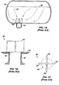
- a vessel 10 illustrated in FIGS. 1A-1C has a basic vaned vortex breaker 30 to reduce vortex and swirling flow in the vessel's outlet 14.
- the breaker 30 has vanes 32 welded to the interior of the vessel's wall 12 over the outlet 14.
- the breaker 30 has four vanes 32 made from two side plates welded to a lager central plate.
- the vortex breaker 30 over the outlet's mouth 16 is intended to break this tendency and to reduce its ill effects.
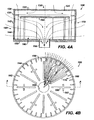
- FIGS. 2A-2D fits over a vessel's outlet 14 to reduce the tendency of vortex and swirling flow in the fluid exiting the vessel 10.
- This type of vortex breaker 40 is similar to that manufactured by Johnson Screens.
- the breaker 40 has a screen basket 41 that fits over several vanes 50.
- the screen basket 41 has a flat top 42, a cylindrical sidewall 44, a bottom 46, and an outlet insert 48. Both the flat top 42 and cylindrical sidewall 44 are composed of wire screens that have wedged-shaped or profiled wires commonly used in the fluid industry, such as the VEE-WIRES ® available from Johnson Screens (VEE-WIRE is a registered trademark).
- VEE-WIRES ® available from Johnson Screens (VEE-WIRE is a registered trademark).
- the vanes 50 fit around a central opening 47 in the breaker's bottom 46, and inner and outer rings 52 and 54 can support the upper corners of the vanes 50.
- This vortex breaker 40 use a baffle plate under the top screen 42.
- the basic vaned vortex breaker 30 of FIGS. 1A-1C and the screen breaker 40 of FIG. 2A-2D may be ineffective in some implementations.
- the basic vaned vortex breaker 30 of FIGS. 1A-1C can be ineffective in LNG applications because properties of LNG tend to produce turbulent flow and/or small vortexes beyond the breaker's vanes 32, producing ill effects in the outlet 14.
- the screen basket breaker 40 with internal vanes 50 of FIGS. 2A-2D must typically have a significantly large size in comparison to the mouth 16 of the outlet 14 to be effective in breaking vortex flow.
- the breaker 40 may need to have a diameter that is about 4 to 5 times the diameter of the outlet's mouth 16, although the actual size may further depend on the fluid type, flow rates, and other variables. The required larger size for the breaker 40 limits its effectiveness in various sized vessels and even limits its use in some situations altogether.
- US 5,096,578 describes a vortex breaker for a liquid draw off tray with horizontal liquid draw off. Liquid is removed from the sump of the tray horizontally through a port.
- a first vertically oriented baffle has a top edge above the port, a bottom edge below the port and a side edge adjacent the port.
- a second vertically oriented baffle is perpendicular to the first baffle. The second baffle has a top edge above the port and a bottom edge spaced from the sump bottom a distance to about one-half port diameter, allowing for the flow of liquid thereunder.
- the vortex breaker is useful for a liquid spare horizontal liquid draw off tray.
- a first aspect of the present invention relates to a vessel apparatus.
- the apparatus may comprise a screen basket disposing in a vessel for enclosing an outlet of the vessel.
- the apparatus may comprise a flow modifier disposed within the basket adjacent the outlet.
- the flow modifier may include a plurality of vanes disposed radially around the outlet. At least some of the vanes may have cross-tees extending from sides of the vanes.
- Each of the vanes may comprise a first end positioned adjacent the outlet.
- Each of the vanes may comprise a second end positioned adjacent a sidewall of the screen basket.
- Each of the vanes may comprise a first edge affixed to a base of the screen basket.
- Each of the vanes may comprise a second edge positioned adjacent a top of the screen basket.
- the vanes may comprise first vanes being first planar plates.
- the vanes may comprise second vanes being second planar plates.
- the second planar plates may have the cross-tees extending from both planar sides of the plates.
- the first and second vanes may be alternatingly arranged around the outlet.
- the cross-tees may be disposed on the second vanes at a first distance from a sidewall of the screen basket that is less than a second distance from the outlet.
- the cross-tees may extend from both planar sides of the plates by a first distance that is less than half of a second distance between the adjacent first and second vanes.
- the flow modifier may comprise at least one stabilizer affixed to top edges of at least some of the vanes.
- the basket may comprise a base having an opening communicating with the outlet.
- the basket may comprise a sidewall screen having a plurality of first wires arranged around a plurality of first bars extending from the base.
- the basket may comprise a top screen positioned on the sidewall screen and may have a plurality of second wires arranged across a plurality of second bars.
- the apparatus may further comprise a baffle plate disposed between the top screen and the flow modifier.
- the baffle plate may restrict fluid flow passing through the top screen to a peripheral edge of the baffle plate adjacent the sidewall screen.
- the baffle plate may redirect at least some of the screened fluid flow that is substantially coincident with an axis of the outlet to be substantially perpendicular to the axis.
- Each of the first wires may comprise a profiled wire having a wider side exposed outside the basket and may have a narrower side welded to the first bars.
- Each of the second bars may have ends affixed to a surrounding band.
- the surrounding band may be affixed to the sidewall screen.
- the sidewall screen may comprise a plurality of modular panels connected together.
- the apparatus may comprise a base disposing in the vessel adjacent the outlet and having an opening communicating with the outlet.
- the basket may be disposed on the base.
- the basket may comprise a sidewall screen having a plurality of first wires arranged around a plurality of first bars extending from the base.
- the basket may comprise a top screen disposed on the sidewall screen and may have a plurality of second wires arranged across a plurality of second bars.
- the plurality of vanes of the flow modifier may extend from the base and may be disposed radially around the opening in the base.
- the vanes may radially direct the screened fluid flow to the outlet.
- the cross-tees may perpendicularly break at least some of the radially directed fluid flow.
- the cross-tees for breaking may be alternatingly disposed around the outlet.
- the apparatus may further comprise a shell of the vessel defining a hollow and having the outlet.
- the screen basket may be disposed in the hollow of the shell and may enclose the outlet.
- a further aspect of the present invention relates to a vortex prevention apparatus.
- the apparatus may comprise a screen basket disposing in a vessel for enclosing an outlet of the vessel.
- the apparatus may comprise a flow modifier disposed within the basket adjacent the outlet.
- the flow modifier may comprise a plurality of vanes disposed radially around the outlet. At least some of the vanes may have cross-tees extending from sides of the vanes.
- Each of the vanes may comprise a first end positioned adjacent the outlet.
- Each of the vanes may comprise a second end positioned adjacent a sidewall of the screen basket.
- Each of the vanes may comprise a first edge affixed to a base of the screen basket.
- Each of the vanes may comprise a second edge positioned adjacent a top of the screen basket.
- the vanes may comprise first vanes being first planar plates.
- the vanes may comprise second vanes being second planar plates.
- the second planar plates may have the cross-tees extending from both planar sides of the plates.
- the first and second vanes may be alternatingly arranged around the outlet.
- the cross-tees may be disposed on the second vanes at a first distance from a sidewall of the screen basket that is less than a second distance from the outlet.
- the cross-tees may extend from both planar sides of the plates by a first distance that is less than half of a second distance between the adjacent first and second vanes.
- the flow modifier may comprise at least one stabilizer affixed to top edges of at least some of the vanes.
- the basket may comprise a base having an opening communicating with the outlet.
- the basket may comprise a sidewall screen having a plurality of first wires arranged around a plurality of first bars extending from the base.
- the basket may comprise a top screen positioned on the sidewall screen and may have a plurality of second wires arranged across a plurality of second bars.
- the apparatus may further comprise a baffle plate disposed between the top screen and the flow modifier.
- the baffle plate may restrict fluid flow passing through the top screen to a peripheral edge of the baffle plate adjacent the sidewall screen.
- Each of the first wires may comprise a profiled wire having a wider side exposed outside the basket and may have a narrower side welded to the first bars.
- Each of the second bars may have ends affixed to a surrounding band.
- the surrounding band may be affixed to the sidewall screen.
- the sidewall screen may comprise a plurality of modular panels connected together.
- a further aspect of the present invention relates to a vortex prevention apparatus.
- the apparatus may comprise a base disposing in a vessel adjacent an outlet.
- the base may have an opening communicating with the outlet.
- the apparatus may comprise a basket disposed on the base.
- the basket may comprise a sidewall screen having a plurality of first wires arranged around a plurality of first bars extending from the base.
- the basket may comprise a top screen disposed on the sidewall screen and having a plurality of second wires arranged across a plurality of second bars.
- the apparatus may comprise a flow modifier disposed within the basket.
- the flow modifier may comprise a plurality of vanes extending from the base.
- the vanse may be disposed radially around the opening in the base. At least some of the vanes may have cross-tees extending from sides of the vanes.
- a further aspect of the present invention relates to a vortex prevention apparatus.
- the apparatus may comprise means for screening fluid flow from inside a vessel to an outlet.
- the apparatus may comprise means for radially directing the screened fluid flow to the outlet.
- the apparatus may comprise means for perpendicularly breaking at least some of the radially directed fluid flow.
- the apparatus may further comprise means for redirecting at least some of the screened fluid flow that is substantially coincident with an axis of the outlet to be substantially perpendicular to the axis.
- the means for breaking may be alternatingly disposed around the outlet.
- a further aspect of the present invention relates to a vessel.
- the vesssel may comprise a shell defining a hollow and may have an outlet.
- the vessel may comprise a screen basket disposed in the hollow of the shell.
- the screen basket may enclose the outlet.
- the vessel may comprise a flow modifier disposed within the basket.
- the flow modifier may comprise a plurality of vanes disposed radially around the outlet. At least some of the vanes may have cross-tees extending from sides of the vanes.
- FIG. 1A shows a horizontal vessel having a vortex breaker according to the prior art.
- FIGS. 1B-1C show side and top view of the vortex breaker of FIG. 1A .
- FIG. 2A shows a vertical vessel having another vortex breaker according to the prior art.
- FIGS. 2B-2D show front, side, and detailed perspective views of the vortex breaker of FIG. 2A .
- FIGS. 3A-3B show top and side views of a vortex breaker according to the present disclosure.
- FIGS. 4A-4B show top and side views of exposed portions of the vortex breaker of FIGS. 3A-3B revealing additional components.
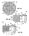
- FIG. 5A shows a top view of another vortex breaker according to the present disclosure.
- FIG. 5B shows a side view with partial cutaway of the vortex breaker of FIG. 5A .
- FIG. 5C shows an end view with partial cutaway of the vortex breaker of FIG. 5A .
- FIG. 6 shows the base of the vortex breaker as unassembled.
- FIGS. 7A-7B show a top view and side cross-section of the vortex breaker's outlet insert.
- FIG. 8 shows a quarter panel of the vortex breaker's sidewall.
- FIGS. 9A-9B show cross-sections of the vortex breaker's top screen, banding, and other components.
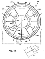
- FIG. 10 shows an exposed top view of the vortex breaker of FIG. 5A revealing the flow modifier therein.
- a vortex breaker fits over a vessel's outlet.
- the breaker has a wire basket with a sidewall screen and a top screen.
- the sidewall screen is disposed on a base, and the base has an opening communicating with the vessel's outlet.
- the basket's sidewall screen has a cylindrical shape with profiled wires horizontally arranged around bars that extend vertically from the base.
- the basket's top screen is attached to the sidewall screen and has a flat, disc shape. As with the sidewall screen, the top screen has wires arranged perpendicularly across a plurality of bars.
- the basket's sidewall screen can have a cylindrical shape with profiled wires vertically arranged around bars that extend horizontally..
- a baffle plate diverts the fluid passing through the top screen to the periphery of the top plate adjacent the sidewall screen.
- a flow modifier has vanes attached to the base and disposed radially around the opening in the base. At least some of these vanes have cross-tees extending from the vane's sides to break the radially directed flow in the basket.
- first planar vanes and second cross-teed vanes are arranged symmetrically and alternating around the central opening in the base.
- a vortex breaker 100 illustrated in FIGS. 3A-3B installs over the outlet of a vessel (not shown), which can be vertical or horizontal.
- the breaker 100 has a screen basket 110 having a top screen 120 and a sidewall screen 140.
- the top screen 120 is disc shaped and positions atop the sidewall screen 140.
- a banding 130 and a rim 135 surround the top screen 120 and attach it to the sidewall screen 140.
- the sidewall screen 140 is cylindrically shaped and is supported on a base 150.
- An outlet insert 155 extends from the base 150 for positioning in a vessel's outlet (e.g., 12; Figs. 1A or 2A ).
- Both the top and sidewall screens 120 can be constructed from several modular screen components coupled together.
- the top screen 120 can be formed from two or more panels coupled together.
- the sidewall screen 140 can be formed from several screen panels or quadrants that couple together to form the screen's cylindrical shape. Because the vessel in which the basket 110 may position may have a curved inner sidewall, the screen 140's lower edges can be contoured to conform to the shape of the vessel.
- the basket's base 150 can be shaped to fit against the vessel's inner wall.
- the sidewall screen 140 has a plurality of horizontally oriented wires 142 attached to and wrapped around a plurality of vertically oriented rods or bars 144.
- These wires 142 are wedge-shaped or profiled wires, such as VEE-WIRES ® known and used in the art for various purposes.
- the bars 144 weld or attached to the base 150, and the wires 142 weld to the bars 144 using techniques known in the art.
- the wires 142 may have their wider sides disposed outwardly around the circumference of the sidewall screen 140 and may have their thinner sides welded to the bars 144. In this way, the wires 142 define gaps or slots between them that form an initial barrier for fluid flow to the vessel's outlet.
- the top screen 120 is similarly constructed of a plurality of wires 122 that weld to perpendicularly arranged bars 124 in a similar fashion. These bars 124 connect at their ends to the surrounding banding 130. In turn, the banding 130 attaches to the rim 135 that affixes atop the cylindrical sidewall screen 140.
- a baffle plate 162 positions below the top screen 120, and its peripheral edge almost extends to the surrounding sidewall screen 140.
- the baffle plate 162 may be set directly underneath and optionally attached to the top screen's bars 124. Alternatively, a gap or space can be provided between the baffle plate 162 and bars 124.
- the baffle plate 162 diverts flow passing through the top screen 120 to the plate's peripheral edge. From this peripheral edge, the diverted flow can then be directed inside the basket 110 to the outlet insert 155.
- the breaker 100 has a flow modifier 160 positioned within the basket 110, as shown in detail in FIGS. 4A-4B .
- the flow modifier 160 positions on the base 150 inside the basket 110 and includes first and second vanes 170/180 radially oriented from the center of the basket 110. These vanes 170/180 can be attached or welded to the surface of the base 150 using techniques known in the art. As best shown in FIG. 4B , the first and second vanes 170 and 180 of the flow modifier 160 are alternatingly and symmetrically arranged around the base's central opening 152.
- the first vanes 170 include planar, solid plates oriented radially from the base's central opening 152.
- the second vanes 180 also include planar, solid plates but have cross-tees 182 positioned perpendicularly thereto. These cross-tees 182 are intended to break radially directed flow. The locations and sizes of these cross-tees 182 depend on the fluid type, flow velocity, flow characteristics, number of vanes, size of the breaker, and other variables evident to those skilled in the art.
- the basket's wire screens 120/140 act as an initial barrier to fluid flow into the breaker 100 and operate to break the tendency of the flow to form vortices and swirls as the fluid passes through the screens 120/140 to the outlet insert 155 disposed in the vessel's outlet.
- the lengthwise bars 124/144 running perpendicular to the wires 122/142 on the inside of the basket 110 also act to control the flow into the basket 110.
- the vanes 170/180 of the flow modifier 160 help radially direct flow in the basket 110 toward the outlet insert 155, and the cross-tees 182 break the radially directed flow in a way that enables the entire breaker 100 to be reduced in overall size.
- prior art breakers may need a diameter that is about 4 to 5 times the outlet's diameter.
- the breaker 100 can be about 1.5 to 3 times the outlet's diameter, although the value depends on the outlet size, flow rate and height of fluid in the vessel during service.
- the breaker 100 preferably prevents vortices with a minimum effect on flow-through resistance or pressure drop. Together, the combination of flow modifier 160 and screen basket 110 create a pressure and streamline pattern that prevent the formation of vortices. Moreover, the screen basket 110 and flow modifier 160 combination can effectively reduce vortices while requiring a smaller sized basket than conventionally used.
- FIGS. 5A-5C Another vortex breaker 200 illustrated in FIGS. 5A-5C is similar to the previously described breaker.
- the breaker 200 has a basket 210 with a top screen 220, a banding 230, a sidewall screen 240, a bottom plate 250, and an outlet insert 255.
- Hold down clips 245 attached around the sides of the breaker 200 connect to tabs (not shown) welded to the inside of a vessel to hold the basket 210 therein.
- the breaker's top screen 220 is surrounded by the banding 230 that attaches the stop screen 220 to the sidewall screen 240.
- the top screen 220 has wires 222 welded to perpendicularly oriented bars 224 that run across the top screen 220.
- a baffle plate 262 positions underneath the top bars 224, which can be welded thereto, and covers most of the top screen 220 except for the outer periphery near the banding 230.
- the sidewall screen 240 of the basket 210 has horizontally oriented wires 242 wrapped around and welded to vertically oriented bars 244. These bars 244 extend from the base 250 and can be welded or affixed thereto in ways known in the art.
- the outlet insert 255 is a cylindrical tube extending from a central opening in this base 250 for passage of fluid out of the basket 210.
- the basket's sidewall screen 240 can have profiled wires 242 horizontally arranged around bars 244 that extend vertically from the base.
- the basket 210 encloses a flow modifier 260 having a plurality of vanes 270/280 disposed inside the breaker 200.
- the flow modifier's vanes 270/280 surround the central opening to the outlet insert 255 and extend radially outward to the surrounding sidewall screen 240.
- Some of the vanes 280 have cross-tees 282 to break the radially directed flow. Further details of the flow modifier 260 are provided below.
- This breaker 200 also has a modular construction.
- the screen basket 210 has first and second halves 212A-B that attach together at the outlet of a vessel (not shown).
- both the top screen 220 and the banding 230 having semi-circular portions that connect together to form the disc shape screen 220 and banding 230.
- the base plate 250 is made of separate components that attach together. These components include central members 258 that connect together and form the plate's central opening 252. End members 256 attach on either side of these central members 258 and can be bent upward to conform to the inside surface of the vessel.
- the outlet insert 255 is a separate cylindrical component having lugs 257.
- the outlet insert 255 fits through the base plate's central opening (252; Fig. 6 ) so it can extend below the base 250.
- the insert's lugs 257 attach to upward extending bolts (253; Fig. 6 ) welded to the base plate (250; Fig. 6 ), although other attachment techniques could be used.
- the sidewall screen 240 of the breaker 200 can be modular and can be composed of quarter panels 246.
- Each of the quarter panels 246 has a surrounding frame 248 to which ends of the vertically oriented bars 244 weld.
- Four such quarter panels 246 bolt end to end to form the cylindrical screen 210, and the lower edges of the frame 248 bolt to the periphery of the base plate (250; Fig. 6 ).
- the banding 230 has a bolting flange 232 that bolts to the top edges of the quarter panel's frame (248; Fig. 8 ).
- the top screen's half disc 220A has a joint flange 234 that bolts to the other complementary half disc of the top screen. ( See e.g., Fig. 5B ).
- the joint flanges 234 couple together near the vanes 280. Therefore, these vanes 280 near the flanges 234 can have a cutaway profile 284 along the top edge to accommodate the shape of the joint flanges 234, but the cross-tees 282 may extend upward beyond the flanges 234.
- the vortex breaker 200 uses the flow modifier 260 and directs flow in a similar manner to that discussed above with reference to FIGS. 3A-4B .
- the inside of the basket 210 has the flow modifier 260 positioned on the base plate 250 around the central opening 252 communicating with the outlet.
- the flow modifier's vanes 270 and 280 are arranged symmetrically and alternatingly around the base plate 250's central opening 252. In the present example, there are twelve vanes 270/280 (six of each) that are arranged at every 30 degrees around the central opening 252, although other arrangements can be used depending on the implementation.
- the first vanes 270 include planar, solid walls oriented radially from the central opening 252. These vanes 270 extend from the central opening 252 radially outward to a point almost to the vertically oriented bars 244 of the sidewall 240.
- the second vanes 280 also include planar, solid walls that are similarly oriented radially from the central opening 252. These vanes 280 also extend from the central opening 252 radially outward to a point almost to the vertically oriented bars 244 of the sidewall 240.
- the second vanes 280 also have cross-tees 282 positioned perpendicularly thereto. As shown, these cross-tees 282 may be positioned relatively closer to the surrounding sidewall 240 as opposed to the central opening 252. Likewise, these cross-tees 282 can encompass half or less than half of the distance d between the second vane 280 and the adjacent first vanes 270.
- semicircular stabilizer bands 264 can attach to outer top corners of the vanes 270/280 near the basket 210's periphery, and curved stabilizer bands 266 can attach to inner corners of the vanes 270 and 280 near the basket 210's center.
- the size, placement, and shape of the vanes 270/280 and cross-tees 282 can be determined based on rules of thumb, equations, guidelines, and other considerations available to one skilled in the art.
- formulas can first be used for estimation, and then computation fluid dynamic (CFD) models can be used.
- CFD computation fluid dynamic
- the breaker 200 is then sized to be large enough to disrupt the shape of the vortex. Sizing ratios for the breaker 200 relative to the size of the vortex that have proven to be successful in previous installations can then be used to finalize the size for the vortex breaker 200. These ratios can vary based on the nozzle size and vessel orientation (horizontal or vertical vessels).
- CFD models are used to determine the streamline pattern for the vessel geometry and nozzle configuration during expected operation.
- the vortex breaker 200 is then added to the CFD model to determine its effects on the streamlines. If the breaker 200 removes the turbulent or swirling streamlines in the CFD model, then the current design of the breaker 200 may be deemed acceptable. If the breaker 200 does not remove the turbulent or swirling streamlines, then the size, number, location and other general configuration variables of the vanes, screen, and other components are altered until the desired flow control effect is observed.
- the basket 210 may have an overall diameter D 1 of about 737-mm (0.737m), and the central opening 252 for the outlet may have a diameter D 2 of about 251-mm (0.251 m).
- the planar portions of the vanes 270/280 may have a length L 1 of about 197-mm (0.197m).
- the cross-tees 282 may have an expanse L 2 of about 102-mm (0.102m) and may be positioned at a distance L 3 about 133.5-mm (0.1335m) from the inner edge of the vanes 280.
- the slot width between the sidewall's wires (242; Figs. 5A-5C ) may be about 6.35-mm (0.00635m), and the slot width between the top screen's wires (222; Figs. 5A-5C ) may be about 4.76-mm (0.00476m).
Landscapes
- Engineering & Computer Science (AREA)
- Mechanical Engineering (AREA)
- General Engineering & Computer Science (AREA)
- Physics & Mathematics (AREA)
- Fluid Mechanics (AREA)
- Paper (AREA)
- Structure Of Emergency Protection For Nuclear Reactors (AREA)
- Separating Particles In Gases By Inertia (AREA)
Claims (15)
- Behältervorrichtung (100, 200), die aufweist:eine Siebtrommel (110, 210), die in einem Behälter (10) für das Einschließen eines Austrittes (14) des Behälters (10) angeordnet ist; undeinen Strömungsmodifizierer (160, 260), der innerhalb der Trommel (110, 210) benachbart dem Austritt (14) angeordnet ist, wobei der Strömungsmodifizierer (160, 260) mindestens umfasst:eine Vielzahl von Flügeln (170, 180, 270, 280), die radial um den Austritt (14) angeordnet sind, wobei mindestens einige der Flügel (180, 280) Quer-T-Stücke (182, 282) aufweisen, die sich von den Seiten der Flügel (180, 280) aus erstrecken.
- Vorrichtung (100, 200) nach Anspruch 1, bei der ein jeder der Flügel (170, 180, 270, 280) aufweist:ein erstes Ende, das benachbart dem Austritt (14) positioniert ist;ein zweites Ende, das benachbart einer Seitenwand der Siebtrommel (110, 210) positioniert ist;einen ersten Rand, der an einer Basis der Siebstrommel (110, 210) befestigt ist; und einen zweiten Rand, der benachbart einer Oberseite der Siebtrommel (110, 210) positioniert ist.
- Vorrichtung (100, 200) nach Anspruch 1 oder 2, bei der die Flügel (170, 180, 270, 280) erste Flügel (170, 270), die erste ebene Platten sind, und zweite Flügel (180, 280) aufweisen, die zweite ebene Platten sind, die die Quer-T-Stücke (182, 282) aufweisen, die sich von beiden ebenen Seiten der Platten aus erstrecken, wobei die ersten und die zweiten Flügel (170, 180, 270, 280) abwechselnd um den Austritt (14) angeordnet sind.
- Vorrichtung (100, 200) nach Anspruch 3,
bei der die Quer-T-Stücke (182, 282) an den zweiten Flügeln (180, 280) mit einem ersten Abstand von einer Seitenwand der Siebtrommel (110, 210) angeordnet sind, der kleiner ist als ein zweiter Abstand vom Austritt (14); oder
bei der sich die Quer-T-Stücke (182, 282) von beiden ebenen Seiten der Platten mit einem ersten Abstand erstrecken, der kleiner ist als die Hälfte eines zweiten Abstandes zwischen den benachbarten ersten und zweiten Flügeln (170, 180, 270, 280). - Vorrichtung (100, 200) nach einem der vorhergehenden Ansprüche, bei der der Strömungsmodifizierer (260) mindestens einen Stabilisator (264) aufweist, der an den oberen Rändern von mindestens einigen der Flügel (270, 280) befestigt ist.
- Vorrichtung (100, 200) nach einem der vorhergehenden Ansprüche, bei der die Trommel (210) aufweist:eine Basis (250) mit einer Öffnung (252), die mit dem Austritt (14) in Verbindung steht;ein Seitenwandsieb (240) mit einer Vielzahl von ersten Drähten (242), die um eine Vielzahl von ersten Stäben (244) angeordnet sind, die sich von der Basis (250) aus erstrecken; undein oberes Sieb (220), das am Seitenwandsieb (240) positioniert ist und eine Vielzahl von zweiten Drähten (222) aufweist, die über eine Vielzahl von zweiten Stäben (224) angeordnet sind.
- Vorrichtung (100, 200) nach Anspruch 6, die außerdem ein Leitblech (262) aufweist, das zwischen dem oberen Sieb (220) und dem Strömungsmodifizierer (260) angeordnet ist, wobei das Leitblech (262) den Fluidstrom begrenzt, der durch das obere Sieb (220) zu einem Umfangsrand des Leitbleches (262) benachbart dem Seitenwandsieb (240) gelangt.
- Vorrichtung (100, 200) nach Anspruch 7, bei der das Leitblech (262) mindestens einiges vom gesiebten Fluidstrom umlenkt, der im Wesentlichen mit einer Achse des Austritts (14) zusammenfällt, um im Wesentlichen senkrecht zur Achse zu verlaufen.
- Vorrichtung (100, 200) nach einem der Ansprüche 6 bis 8, bei der ein jeder der ersten Drähte (242) einen Profildraht aufweist, der eine breitere Seite, die außerhalb der Trommel (210) freigelegt ist, und eine schmalere Seite aufweist, die an den ersten Stäben (244) angeschweißt ist.
- Vorrichtung (100, 200) nach einem der Ansprüche 6 bis 9, bei der ein jeder der zweiten Stäbe (224) Enden aufweist, die an einem umgebenden Band (230) befestigt sind; und
bei der wahlweise das umgebende Band (230) am Seitenwandsieb (240) befestigt ist. - Vorrichtung (100, 200) nach einem der Ansprüche 6 bis 10, bei der das Seitenwandsieb (240) eine Vielzahl von modularen Platten (246) aufweist, die miteinander verbunden sind.
- Vorrichtung (100, 200) nach einem der vorhergehenden Ansprüche, die aufweist:eine Basis (250), die im Behälter (200) benachbart dem Austritt (14) angeordnet ist und eine Öffnung aufweist, die mit dem Austritt (14) in Verbindung steht;wobei die Trommel (210) auf der Basis (250) angeordnet ist, wobei die Trommel (210) mindestens umfasst:ein Seitenwandsieb (240) mit einer Vielzahl von ersten Drähten (242), die um eine Vielzahl von ersten Stäben (244) angeordnet sind, die sich von der Basis (250) aus erstrecken; undein oberes Sieb (220), das am Seitenwandsieb (240) angeordnet ist und eine Vielzahl von zweiten Drähten (222) aufweist, die über eine Vielzahl von zweiten Stäben (224) angeordnet sind; undwobei sich die Vielzahl der Flügel (270, 280) des Strömungsmodifizierers (260) von der Basis (250) aus erstreckt und radial um die Öffnung (252) in der Basis (250) angeordnet ist.
- Vorrichtung (100, 200) nach einem der vorhergehenden Ansprüche,
bei der die Flügel (170, 180, 270, 280) radial den gesiebten Fluidstrom zum Austritt (14) lenken; und
wobei die Quer-T-Stücke (182, 282) senkrecht mindestens etwas vom radial ausgerichteten Fluidstrom unterbrechen. - Vorrichtung (100, 200) nach Anspruch 13, bei der die Quer-T-Stücke (182, 282) für das Unterbrechen abwechselnd um den Austritt angeordnet sind.
- Vorrichtung (100, 200) nach einem der vorhergehenden Ansprüche, die außerdem aufweist:eine Hülle des Behälters (10), die einen Hohlraum definiert und den Austritt (14) aufweist;wobei die Siebstrommel (110, 210) im Hohlraum der Hülle angeordnet ist und den Austritt (14) einschließt.
Applications Claiming Priority (1)
| Application Number | Priority Date | Filing Date | Title |
|---|---|---|---|
| US13/117,695 US8439071B2 (en) | 2011-05-27 | 2011-05-27 | Screen basket vortex breaker for vessel |
Publications (3)
| Publication Number | Publication Date |
|---|---|
| EP2532439A2 EP2532439A2 (de) | 2012-12-12 |
| EP2532439A3 EP2532439A3 (de) | 2013-04-10 |
| EP2532439B1 true EP2532439B1 (de) | 2014-12-03 |
Family
ID=46172705
Family Applications (1)
| Application Number | Title | Priority Date | Filing Date |
|---|---|---|---|
| EP20120169657 Active EP2532439B1 (de) | 2011-05-27 | 2012-05-25 | Siebtrommelwirbelbrecher für Behälter |
Country Status (5)
| Country | Link |
|---|---|
| US (2) | US8439071B2 (de) |
| EP (1) | EP2532439B1 (de) |
| JP (2) | JP5579777B2 (de) |
| AU (1) | AU2012202781B2 (de) |
| CA (1) | CA2776606C (de) |
Families Citing this family (20)
| Publication number | Priority date | Publication date | Assignee | Title |
|---|---|---|---|---|
| US8439071B2 (en) * | 2011-05-27 | 2013-05-14 | Johnson Screens, Inc. | Screen basket vortex breaker for vessel |
| FR2981332B1 (fr) * | 2011-10-18 | 2014-03-07 | Astrium Sas | Dispositif d'expulsion/retention de liquides pour reservoir d'engin spatial |
| US8651137B2 (en) * | 2011-10-21 | 2014-02-18 | Crossroads Machine Inc. | Gas manifold system for steady gas supply at outlet |
| US20130206263A1 (en) * | 2012-02-13 | 2013-08-15 | Anthony Brownlow | Vortex control apparatus |
| US10039240B2 (en) | 2013-08-14 | 2018-08-07 | Richard Alan Darnold | Device for monitoring and controlling water flow |
| US9970389B2 (en) * | 2014-03-06 | 2018-05-15 | The Boeing Company | Antivortex device and method of assembling thereof |
| AU2015252986B2 (en) * | 2014-05-01 | 2019-07-11 | Conocophillips Company | Liquid drains in core-in-shell heat exchanger |
| KR101812688B1 (ko) * | 2015-11-27 | 2017-12-27 | (주)아성엠 | 티핑 버킷형 우설량 계측 장치 |
| US10309432B2 (en) * | 2016-06-22 | 2019-06-04 | Fmc Technologies, Inc. | Flow conditioner |
| CN111556781B (zh) | 2017-12-06 | 2022-03-29 | 康明斯滤清系统知识产权公司 | 具有减小切向流出流体压降的涡流破坏器的曲轴箱通风系统 |
| AU2019333933A1 (en) | 2018-09-06 | 2021-05-13 | Sand Separation Technologies Inc. | Counterflow vortex breaker |
| RU186449U1 (ru) * | 2018-09-14 | 2019-01-21 | Акционерное общество "Корпорация "Стратегические пункты управления" АО "Корпорация "СПУ - ЦКБ ТМ" | Устройство предотвращения образования водоворота |
| US20200149549A1 (en) * | 2018-11-09 | 2020-05-14 | Agco International Gmbh | Vortex adaption preventer |
| CN109987344A (zh) * | 2019-05-08 | 2019-07-09 | 张化机(苏州)重装有限公司 | 一种格栅立柱式防涡流器 |
| CN110027811A (zh) * | 2019-05-08 | 2019-07-19 | 张化机(苏州)重装有限公司 | 一种防涡流器 |
| CN111550476B (zh) * | 2020-04-29 | 2025-03-25 | 浙江理工大学 | 用于流程阀门出流的整流装置 |
| KR102236202B1 (ko) * | 2020-09-24 | 2021-04-06 | (주)에스티아이 | 약액 공급 탱크 |
| CN115930091B (zh) * | 2022-12-06 | 2024-03-22 | 中太能源科技(上海)有限公司 | 一种具有热胀冷缩功能角体连接结构件 |
| CN115818756A (zh) * | 2023-02-14 | 2023-03-21 | 珠海巨涛海洋石油服务有限公司 | 一种液相出口防涡器 |
| WO2025000026A1 (en) * | 2023-06-28 | 2025-01-02 | Johnson Screens, Inc. | Fish and debris exclusion screen assembly |
Family Cites Families (21)
| Publication number | Priority date | Publication date | Assignee | Title |
|---|---|---|---|---|
| US1391083A (en) * | 1919-04-08 | 1921-09-20 | Johns Machine And Stamping Wor | Wagon |
| US1473667A (en) * | 1922-03-14 | 1923-11-13 | Arthur W Burks | Combined foot valve and strainer |
| US3986525A (en) * | 1975-01-31 | 1976-10-19 | Anderson, Greenwood & Co. | Internal tank valve |
| US4068683A (en) * | 1975-09-09 | 1978-01-17 | Control Components, Inc. | High energy loss device |
| US4051042A (en) * | 1975-12-15 | 1977-09-27 | Tullier Leo D | Fluid flow filtering arrangement |
| US4696741A (en) | 1986-04-18 | 1987-09-29 | Phillips Petroleum Company | Vortex breaker for use in a liquid-liquid separator or the like |
| US4768541A (en) * | 1986-11-03 | 1988-09-06 | Martin Marietta Corporation | Means of expelling parallel tanks to low residuals |
| GB8713308D0 (en) * | 1987-06-06 | 1987-07-08 | Clean Water Co Ltd | Separators |
| US4922948A (en) * | 1989-06-01 | 1990-05-08 | Willem Van Dijk | Floor drain and trap |
| US5096578A (en) | 1990-08-15 | 1992-03-17 | Texaco Inc. | Vortex breaker for horizontal liquid draw off tray sump |
| FR2683003B1 (fr) * | 1991-10-25 | 1995-02-17 | Schlumberger Ind Sa | Redresseur de flux. |
| JPH07187282A (ja) * | 1993-12-28 | 1995-07-25 | Ishikawajima Harima Heavy Ind Co Ltd | 貯液タンク |
| US5477803A (en) * | 1994-06-30 | 1995-12-26 | The United States Of America As Represented By The Secretary Of The Navy | Torpedo tube and slide valve grates |
| US5666987A (en) * | 1995-03-24 | 1997-09-16 | Combs; Glenn A. | Chemical dispersing apparatus |
| US5790619A (en) | 1997-01-15 | 1998-08-04 | Combustion Engineering, Inc. | Drain system for a nuclear power plant |
| US6014987A (en) * | 1998-05-11 | 2000-01-18 | Lockheed Martin Corporation | Anti-vortex baffle assembly with filter for a tank |
| US6382148B1 (en) * | 1999-06-10 | 2002-05-07 | Unisia Jecs Corporation | Oil pressure control apparatus for an internal combustion engine |
| US6591867B2 (en) * | 2001-09-21 | 2003-07-15 | The Boeing Company | Variable-gravity anti-vortex and vapor-ingestion-suppression device |
| US20090211965A1 (en) * | 2008-02-21 | 2009-08-27 | Weatherford/Lamb, Inc. | Arrangement for splicing panels together to form a cylindrical screen |
| JP2010174511A (ja) * | 2009-01-29 | 2010-08-12 | Kansai Electric Power Co Inc:The | 朝顔型取水構造体 |
| US8439071B2 (en) * | 2011-05-27 | 2013-05-14 | Johnson Screens, Inc. | Screen basket vortex breaker for vessel |
-
2011
- 2011-05-27 US US13/117,695 patent/US8439071B2/en active Active
-
2012
- 2012-05-10 CA CA2776606A patent/CA2776606C/en not_active Expired - Fee Related
- 2012-05-11 AU AU2012202781A patent/AU2012202781B2/en not_active Ceased
- 2012-05-25 EP EP20120169657 patent/EP2532439B1/de active Active
- 2012-05-26 JP JP2012120339A patent/JP5579777B2/ja not_active Expired - Fee Related
-
2013
- 2013-05-13 US US13/893,101 patent/US9328869B2/en not_active Expired - Fee Related
-
2014
- 2014-07-08 JP JP2014140912A patent/JP6155428B2/ja active Active
Also Published As
| Publication number | Publication date |
|---|---|
| JP6155428B2 (ja) | 2017-07-05 |
| JP2014196147A (ja) | 2014-10-16 |
| EP2532439A3 (de) | 2013-04-10 |
| AU2012202781B2 (en) | 2014-11-06 |
| EP2532439A2 (de) | 2012-12-12 |
| CA2776606C (en) | 2016-08-09 |
| JP2012246060A (ja) | 2012-12-13 |
| US20120298232A1 (en) | 2012-11-29 |
| US9328869B2 (en) | 2016-05-03 |
| CA2776606A1 (en) | 2012-11-27 |
| JP5579777B2 (ja) | 2014-08-27 |
| US8439071B2 (en) | 2013-05-14 |
| US20130248028A1 (en) | 2013-09-26 |
| AU2012202781A1 (en) | 2012-12-13 |
Similar Documents
| Publication | Publication Date | Title |
|---|---|---|
| EP2532439B1 (de) | Siebtrommelwirbelbrecher für Behälter | |
| RU2680896C1 (ru) | Нагнетательное устройство и наружный блок кондиционера воздуха, содержащий его | |
| JP6285922B2 (ja) | 半径流反応器内で固体材料を保持するための装置及び形成方法 | |
| US20150300372A1 (en) | Diffusor, ventilator having such a diffusor, and device having such ventilators | |
| KR101070344B1 (ko) | 방사류 리액터용 무스크린 내부 통로 | |
| WO2015060217A1 (ja) | 摩擦抵抗低減装置、これを備えている船舶、船舶の摩擦抵抗低減方法 | |
| KR100919269B1 (ko) | 전면에 루버를 구비한 유입 덕트를 포함하는 유체 유도장치 | |
| JP4430675B2 (ja) | 物質移動コラム用流体流供給装置 | |
| JP2019105252A (ja) | 渦防止装置を備えたポンプ | |
| JP2020512933A (ja) | 容器内の液体流の相を分離するための入口装置及び同装置を含む方法 | |
| AU2008311108A1 (en) | Metallurgical impact pad | |
| EP3299592B1 (de) | Abdampfgehäuse für ein niederdruckdampfturbinensystem | |
| US10384181B2 (en) | Tapered conduits for reactors | |
| JP5881407B2 (ja) | 気液分離器 | |
| JP6472738B2 (ja) | 渦防止装置、および渦防止装置を備えるポンプ設備 | |
| JP2005009999A (ja) | 原子炉の炉内構造 | |
| JP2020199485A (ja) | 気液分離器 | |
| WO2022271470A1 (en) | Refractory impact pad | |
| WO2014015906A1 (en) | Inlet device for separator | |
| RU2010138439A (ru) | Газовый ковер | |
| ITTO20111003A1 (it) | Bruciatore a gas, in particolare per un apparecchio di cottura | |
| EP2652342A1 (de) | Rohrleitungseinbauten zur steuerung von gas-flüssigkeits-stromteilung |
Legal Events
| Date | Code | Title | Description |
|---|---|---|---|
| PUAI | Public reference made under article 153(3) epc to a published international application that has entered the european phase |
Free format text: ORIGINAL CODE: 0009012 |
|
| 17P | Request for examination filed |
Effective date: 20120525 |
|
| AK | Designated contracting states |
Kind code of ref document: A2 Designated state(s): AL AT BE BG CH CY CZ DE DK EE ES FI FR GB GR HR HU IE IS IT LI LT LU LV MC MK MT NL NO PL PT RO RS SE SI SK SM TR |
|
| AX | Request for extension of the european patent |
Extension state: BA ME |
|
| PUAL | Search report despatched |
Free format text: ORIGINAL CODE: 0009013 |
|
| AK | Designated contracting states |
Kind code of ref document: A3 Designated state(s): AL AT BE BG CH CY CZ DE DK EE ES FI FR GB GR HR HU IE IS IT LI LT LU LV MC MK MT NL NO PL PT RO RS SE SI SK SM TR |
|
| AX | Request for extension of the european patent |
Extension state: BA ME |
|
| RIC1 | Information provided on ipc code assigned before grant |
Ipc: F17C 13/04 20060101ALI20130305BHEP Ipc: B04C 5/02 20060101AFI20130305BHEP |
|
| 17Q | First examination report despatched |
Effective date: 20131121 |
|
| REG | Reference to a national code |
Ref country code: DE Ref legal event code: R079 Ref document number: 602012004057 Country of ref document: DE Free format text: PREVIOUS MAIN CLASS: B04C0005020000 Ipc: F15D0001000000 |
|
| RIC1 | Information provided on ipc code assigned before grant |
Ipc: F15D 1/00 20060101AFI20140415BHEP Ipc: F17C 13/04 20060101ALI20140415BHEP |
|
| GRAP | Despatch of communication of intention to grant a patent |
Free format text: ORIGINAL CODE: EPIDOSNIGR1 |
|
| INTG | Intention to grant announced |
Effective date: 20140612 |
|
| GRAS | Grant fee paid |
Free format text: ORIGINAL CODE: EPIDOSNIGR3 |
|
| GRAA | (expected) grant |
Free format text: ORIGINAL CODE: 0009210 |
|
| AK | Designated contracting states |
Kind code of ref document: B1 Designated state(s): AL AT BE BG CH CY CZ DE DK EE ES FI FR GB GR HR HU IE IS IT LI LT LU LV MC MK MT NL NO PL PT RO RS SE SI SK SM TR |
|
| REG | Reference to a national code |
Ref country code: GB Ref legal event code: FG4D |
|
| REG | Reference to a national code |
Ref country code: CH Ref legal event code: EP Ref country code: AT Ref legal event code: REF Ref document number: 699530 Country of ref document: AT Kind code of ref document: T Effective date: 20141215 |
|
| REG | Reference to a national code |
Ref country code: IE Ref legal event code: FG4D |
|
| REG | Reference to a national code |
Ref country code: DE Ref legal event code: R096 Ref document number: 602012004057 Country of ref document: DE Effective date: 20150115 |
|
| REG | Reference to a national code |
Ref country code: DE Ref legal event code: R082 Ref document number: 602012004057 Country of ref document: DE Representative=s name: MARKS & CLERK (LUXEMBOURG) LLP, LU |
|
| RAP2 | Party data changed (patent owner data changed or rights of a patent transferred) |
Owner name: BILFINGER WATER TECHNOLOGIES, INC. |
|
| REG | Reference to a national code |
Ref country code: NL Ref legal event code: VDEP Effective date: 20141203 |
|
| REG | Reference to a national code |
Ref country code: AT Ref legal event code: MK05 Ref document number: 699530 Country of ref document: AT Kind code of ref document: T Effective date: 20141203 |
|
| PG25 | Lapsed in a contracting state [announced via postgrant information from national office to epo] |
Ref country code: LT Free format text: LAPSE BECAUSE OF FAILURE TO SUBMIT A TRANSLATION OF THE DESCRIPTION OR TO PAY THE FEE WITHIN THE PRESCRIBED TIME-LIMIT Effective date: 20141203 Ref country code: ES Free format text: LAPSE BECAUSE OF FAILURE TO SUBMIT A TRANSLATION OF THE DESCRIPTION OR TO PAY THE FEE WITHIN THE PRESCRIBED TIME-LIMIT Effective date: 20141203 Ref country code: NO Free format text: LAPSE BECAUSE OF FAILURE TO SUBMIT A TRANSLATION OF THE DESCRIPTION OR TO PAY THE FEE WITHIN THE PRESCRIBED TIME-LIMIT Effective date: 20150303 Ref country code: NL Free format text: LAPSE BECAUSE OF FAILURE TO SUBMIT A TRANSLATION OF THE DESCRIPTION OR TO PAY THE FEE WITHIN THE PRESCRIBED TIME-LIMIT Effective date: 20141203 Ref country code: FI Free format text: LAPSE BECAUSE OF FAILURE TO SUBMIT A TRANSLATION OF THE DESCRIPTION OR TO PAY THE FEE WITHIN THE PRESCRIBED TIME-LIMIT Effective date: 20141203 |
|
| REG | Reference to a national code |
Ref country code: DE Ref legal event code: R081 Ref document number: 602012004057 Country of ref document: DE Owner name: AQSEPTENCE GROUP, INC., WILMINGTON, US Free format text: FORMER OWNER: JOHNSON SCREENS, INC., HOUSTON, TEX., US Effective date: 20150401 Ref country code: DE Ref legal event code: R082 Ref document number: 602012004057 Country of ref document: DE Representative=s name: MARKS & CLERK (LUXEMBOURG) LLP, LU Effective date: 20150401 Ref country code: DE Ref legal event code: R081 Ref document number: 602012004057 Country of ref document: DE Owner name: BILFINGER WATER TECHNOLOGIES, INC., HOUSTON, US Free format text: FORMER OWNER: JOHNSON SCREENS, INC., HOUSTON, TEX., US Effective date: 20150401 Ref country code: DE Ref legal event code: R081 Ref document number: 602012004057 Country of ref document: DE Owner name: AQSEPTENCE GROUP, INC., NEW BRIGHTON, US Free format text: FORMER OWNER: JOHNSON SCREENS, INC., HOUSTON, TEX., US Effective date: 20150401 |
|
| REG | Reference to a national code |
Ref country code: LT Ref legal event code: MG4D |
|
| PG25 | Lapsed in a contracting state [announced via postgrant information from national office to epo] |
Ref country code: HR Free format text: LAPSE BECAUSE OF FAILURE TO SUBMIT A TRANSLATION OF THE DESCRIPTION OR TO PAY THE FEE WITHIN THE PRESCRIBED TIME-LIMIT Effective date: 20141203 Ref country code: SE Free format text: LAPSE BECAUSE OF FAILURE TO SUBMIT A TRANSLATION OF THE DESCRIPTION OR TO PAY THE FEE WITHIN THE PRESCRIBED TIME-LIMIT Effective date: 20141203 Ref country code: CY Free format text: LAPSE BECAUSE OF FAILURE TO SUBMIT A TRANSLATION OF THE DESCRIPTION OR TO PAY THE FEE WITHIN THE PRESCRIBED TIME-LIMIT Effective date: 20141203 Ref country code: GR Free format text: LAPSE BECAUSE OF FAILURE TO SUBMIT A TRANSLATION OF THE DESCRIPTION OR TO PAY THE FEE WITHIN THE PRESCRIBED TIME-LIMIT Effective date: 20150304 Ref country code: AT Free format text: LAPSE BECAUSE OF FAILURE TO SUBMIT A TRANSLATION OF THE DESCRIPTION OR TO PAY THE FEE WITHIN THE PRESCRIBED TIME-LIMIT Effective date: 20141203 Ref country code: RS Free format text: LAPSE BECAUSE OF FAILURE TO SUBMIT A TRANSLATION OF THE DESCRIPTION OR TO PAY THE FEE WITHIN THE PRESCRIBED TIME-LIMIT Effective date: 20141203 Ref country code: LV Free format text: LAPSE BECAUSE OF FAILURE TO SUBMIT A TRANSLATION OF THE DESCRIPTION OR TO PAY THE FEE WITHIN THE PRESCRIBED TIME-LIMIT Effective date: 20141203 |
|
| PG25 | Lapsed in a contracting state [announced via postgrant information from national office to epo] |
Ref country code: CZ Free format text: LAPSE BECAUSE OF FAILURE TO SUBMIT A TRANSLATION OF THE DESCRIPTION OR TO PAY THE FEE WITHIN THE PRESCRIBED TIME-LIMIT Effective date: 20141203 Ref country code: PT Free format text: LAPSE BECAUSE OF FAILURE TO SUBMIT A TRANSLATION OF THE DESCRIPTION OR TO PAY THE FEE WITHIN THE PRESCRIBED TIME-LIMIT Effective date: 20150403 Ref country code: EE Free format text: LAPSE BECAUSE OF FAILURE TO SUBMIT A TRANSLATION OF THE DESCRIPTION OR TO PAY THE FEE WITHIN THE PRESCRIBED TIME-LIMIT Effective date: 20141203 Ref country code: SK Free format text: LAPSE BECAUSE OF FAILURE TO SUBMIT A TRANSLATION OF THE DESCRIPTION OR TO PAY THE FEE WITHIN THE PRESCRIBED TIME-LIMIT Effective date: 20141203 Ref country code: RO Free format text: LAPSE BECAUSE OF FAILURE TO SUBMIT A TRANSLATION OF THE DESCRIPTION OR TO PAY THE FEE WITHIN THE PRESCRIBED TIME-LIMIT Effective date: 20141203 |
|
| PG25 | Lapsed in a contracting state [announced via postgrant information from national office to epo] |
Ref country code: IS Free format text: LAPSE BECAUSE OF FAILURE TO SUBMIT A TRANSLATION OF THE DESCRIPTION OR TO PAY THE FEE WITHIN THE PRESCRIBED TIME-LIMIT Effective date: 20150403 Ref country code: PL Free format text: LAPSE BECAUSE OF FAILURE TO SUBMIT A TRANSLATION OF THE DESCRIPTION OR TO PAY THE FEE WITHIN THE PRESCRIBED TIME-LIMIT Effective date: 20141203 |
|
| REG | Reference to a national code |
Ref country code: DE Ref legal event code: R097 Ref document number: 602012004057 Country of ref document: DE |
|
| PLBE | No opposition filed within time limit |
Free format text: ORIGINAL CODE: 0009261 |
|
| STAA | Information on the status of an ep patent application or granted ep patent |
Free format text: STATUS: NO OPPOSITION FILED WITHIN TIME LIMIT |
|
| PG25 | Lapsed in a contracting state [announced via postgrant information from national office to epo] |
Ref country code: DK Free format text: LAPSE BECAUSE OF FAILURE TO SUBMIT A TRANSLATION OF THE DESCRIPTION OR TO PAY THE FEE WITHIN THE PRESCRIBED TIME-LIMIT Effective date: 20141203 |
|
| 26N | No opposition filed |
Effective date: 20150904 |
|
| REG | Reference to a national code |
Ref country code: CH Ref legal event code: PL |
|
| PG25 | Lapsed in a contracting state [announced via postgrant information from national office to epo] |
Ref country code: LU Free format text: LAPSE BECAUSE OF FAILURE TO SUBMIT A TRANSLATION OF THE DESCRIPTION OR TO PAY THE FEE WITHIN THE PRESCRIBED TIME-LIMIT Effective date: 20150525 Ref country code: CH Free format text: LAPSE BECAUSE OF NON-PAYMENT OF DUE FEES Effective date: 20150531 Ref country code: MC Free format text: LAPSE BECAUSE OF FAILURE TO SUBMIT A TRANSLATION OF THE DESCRIPTION OR TO PAY THE FEE WITHIN THE PRESCRIBED TIME-LIMIT Effective date: 20141203 Ref country code: LI Free format text: LAPSE BECAUSE OF NON-PAYMENT OF DUE FEES Effective date: 20150531 |
|
| REG | Reference to a national code |
Ref country code: IE Ref legal event code: MM4A |
|
| PG25 | Lapsed in a contracting state [announced via postgrant information from national office to epo] |
Ref country code: SI Free format text: LAPSE BECAUSE OF FAILURE TO SUBMIT A TRANSLATION OF THE DESCRIPTION OR TO PAY THE FEE WITHIN THE PRESCRIBED TIME-LIMIT Effective date: 20141203 |
|
| REG | Reference to a national code |
Ref country code: FR Ref legal event code: PLFP Year of fee payment: 5 |
|
| PG25 | Lapsed in a contracting state [announced via postgrant information from national office to epo] |
Ref country code: IE Free format text: LAPSE BECAUSE OF NON-PAYMENT OF DUE FEES Effective date: 20150525 |
|
| PG25 | Lapsed in a contracting state [announced via postgrant information from national office to epo] |
Ref country code: BE Free format text: LAPSE BECAUSE OF FAILURE TO SUBMIT A TRANSLATION OF THE DESCRIPTION OR TO PAY THE FEE WITHIN THE PRESCRIBED TIME-LIMIT Effective date: 20141203 |
|
| PG25 | Lapsed in a contracting state [announced via postgrant information from national office to epo] |
Ref country code: MT Free format text: LAPSE BECAUSE OF FAILURE TO SUBMIT A TRANSLATION OF THE DESCRIPTION OR TO PAY THE FEE WITHIN THE PRESCRIBED TIME-LIMIT Effective date: 20141203 |
|
| GBPC | Gb: european patent ceased through non-payment of renewal fee |
Effective date: 20160525 |
|
| REG | Reference to a national code |
Ref country code: FR Ref legal event code: PLFP Year of fee payment: 6 |
|
| REG | Reference to a national code |
Ref country code: DE Ref legal event code: R082 Ref document number: 602012004057 Country of ref document: DE Representative=s name: MARKS & CLERK (LUXEMBOURG) LLP, LU Ref country code: DE Ref legal event code: R081 Ref document number: 602012004057 Country of ref document: DE Owner name: AQSEPTENCE GROUP, INC., WILMINGTON, US Free format text: FORMER OWNER: BILFINGER WATER TECHNOLOGIES, INC., HOUSTON, TEX., US Ref country code: DE Ref legal event code: R081 Ref document number: 602012004057 Country of ref document: DE Owner name: AQSEPTENCE GROUP, INC., NEW BRIGHTON, US Free format text: FORMER OWNER: BILFINGER WATER TECHNOLOGIES, INC., HOUSTON, TEX., US |
|
| PG25 | Lapsed in a contracting state [announced via postgrant information from national office to epo] |
Ref country code: HU Free format text: LAPSE BECAUSE OF FAILURE TO SUBMIT A TRANSLATION OF THE DESCRIPTION OR TO PAY THE FEE WITHIN THE PRESCRIBED TIME-LIMIT; INVALID AB INITIO Effective date: 20120525 Ref country code: GB Free format text: LAPSE BECAUSE OF NON-PAYMENT OF DUE FEES Effective date: 20160525 Ref country code: SM Free format text: LAPSE BECAUSE OF FAILURE TO SUBMIT A TRANSLATION OF THE DESCRIPTION OR TO PAY THE FEE WITHIN THE PRESCRIBED TIME-LIMIT Effective date: 20141203 Ref country code: BG Free format text: LAPSE BECAUSE OF FAILURE TO SUBMIT A TRANSLATION OF THE DESCRIPTION OR TO PAY THE FEE WITHIN THE PRESCRIBED TIME-LIMIT Effective date: 20141203 |
|
| PG25 | Lapsed in a contracting state [announced via postgrant information from national office to epo] |
Ref country code: TR Free format text: LAPSE BECAUSE OF FAILURE TO SUBMIT A TRANSLATION OF THE DESCRIPTION OR TO PAY THE FEE WITHIN THE PRESCRIBED TIME-LIMIT Effective date: 20141203 |
|
| REG | Reference to a national code |
Ref country code: DE Ref legal event code: R082 Ref document number: 602012004057 Country of ref document: DE Representative=s name: MARKS & CLERK (LUXEMBOURG) LLP, LU Ref country code: DE Ref legal event code: R081 Ref document number: 602012004057 Country of ref document: DE Owner name: AQSEPTENCE GROUP, INC., NEW BRIGHTON, US Free format text: FORMER OWNER: AQSEPTENCE GROUP, INC., WILMINGTON, DEL., US |
|
| REG | Reference to a national code |
Ref country code: FR Ref legal event code: CA Effective date: 20171005 Ref country code: FR Ref legal event code: CD Owner name: BILFINGER WATER TECHNOLOGIES, INC., US Effective date: 20171005 |
|
| REG | Reference to a national code |
Ref country code: FR Ref legal event code: CA Effective date: 20180119 |
|
| REG | Reference to a national code |
Ref country code: FR Ref legal event code: PLFP Year of fee payment: 7 |
|
| PG25 | Lapsed in a contracting state [announced via postgrant information from national office to epo] |
Ref country code: MK Free format text: LAPSE BECAUSE OF FAILURE TO SUBMIT A TRANSLATION OF THE DESCRIPTION OR TO PAY THE FEE WITHIN THE PRESCRIBED TIME-LIMIT Effective date: 20141203 |
|
| PG25 | Lapsed in a contracting state [announced via postgrant information from national office to epo] |
Ref country code: AL Free format text: LAPSE BECAUSE OF FAILURE TO SUBMIT A TRANSLATION OF THE DESCRIPTION OR TO PAY THE FEE WITHIN THE PRESCRIBED TIME-LIMIT Effective date: 20141203 |
|
| REG | Reference to a national code |
Ref country code: FR Ref legal event code: PLFP Year of fee payment: 12 |
|
| PGFP | Annual fee paid to national office [announced via postgrant information from national office to epo] |
Ref country code: DE Payment date: 20250402 Year of fee payment: 14 |
|
| PGFP | Annual fee paid to national office [announced via postgrant information from national office to epo] |
Ref country code: IT Payment date: 20250422 Year of fee payment: 14 |
|
| PGFP | Annual fee paid to national office [announced via postgrant information from national office to epo] |
Ref country code: FR Payment date: 20250401 Year of fee payment: 14 |