EP2531760B1 - Elément structural microfluidique conçu pour la manipulation d'un fluide et puce microfluidique - Google Patents
Elément structural microfluidique conçu pour la manipulation d'un fluide et puce microfluidique Download PDFInfo
- Publication number
- EP2531760B1 EP2531760B1 EP10800958.0A EP10800958A EP2531760B1 EP 2531760 B1 EP2531760 B1 EP 2531760B1 EP 10800958 A EP10800958 A EP 10800958A EP 2531760 B1 EP2531760 B1 EP 2531760B1
- Authority
- EP
- European Patent Office
- Prior art keywords
- substrate
- control chamber
- recess
- control
- fluid
- Prior art date
- Legal status (The legal status is an assumption and is not a legal conclusion. Google has not performed a legal analysis and makes no representation as to the accuracy of the status listed.)
- Active
Links
- 239000012530 fluid Substances 0.000 title claims description 57
- 239000000758 substrate Substances 0.000 claims description 120
- 239000013013 elastic material Substances 0.000 claims description 7
- 229920001746 electroactive polymer Polymers 0.000 claims description 4
- 238000004137 mechanical activation Methods 0.000 claims description 4
- 238000000018 DNA microarray Methods 0.000 claims description 3
- 230000004913 activation Effects 0.000 description 14
- 238000005516 engineering process Methods 0.000 description 4
- 230000003213 activating effect Effects 0.000 description 3
- 239000012190 activator Substances 0.000 description 3
- 239000007789 gas Substances 0.000 description 3
- 239000007788 liquid Substances 0.000 description 3
- 238000004519 manufacturing process Methods 0.000 description 3
- 238000002156 mixing Methods 0.000 description 2
- 238000000926 separation method Methods 0.000 description 2
- 229920001971 elastomer Polymers 0.000 description 1
- 238000005429 filling process Methods 0.000 description 1
- 239000012528 membrane Substances 0.000 description 1
- 238000000465 moulding Methods 0.000 description 1
- 229920000642 polymer Polymers 0.000 description 1
- 238000005086 pumping Methods 0.000 description 1
- 229920001169 thermoplastic Polymers 0.000 description 1
- 229920002725 thermoplastic elastomer Polymers 0.000 description 1
- 239000004416 thermosoftening plastic Substances 0.000 description 1
- 238000013519 translation Methods 0.000 description 1
- 230000014616 translation Effects 0.000 description 1
Images


Classifications
-
- F—MECHANICAL ENGINEERING; LIGHTING; HEATING; WEAPONS; BLASTING
- F16—ENGINEERING ELEMENTS AND UNITS; GENERAL MEASURES FOR PRODUCING AND MAINTAINING EFFECTIVE FUNCTIONING OF MACHINES OR INSTALLATIONS; THERMAL INSULATION IN GENERAL
- F16K—VALVES; TAPS; COCKS; ACTUATING-FLOATS; DEVICES FOR VENTING OR AERATING
- F16K99/00—Subject matter not provided for in other groups of this subclass
- F16K99/0001—Microvalves
-
- B—PERFORMING OPERATIONS; TRANSPORTING
- B01—PHYSICAL OR CHEMICAL PROCESSES OR APPARATUS IN GENERAL
- B01L—CHEMICAL OR PHYSICAL LABORATORY APPARATUS FOR GENERAL USE
- B01L3/00—Containers or dishes for laboratory use, e.g. laboratory glassware; Droppers
- B01L3/50—Containers for the purpose of retaining a material to be analysed, e.g. test tubes
- B01L3/502—Containers for the purpose of retaining a material to be analysed, e.g. test tubes with fluid transport, e.g. in multi-compartment structures
- B01L3/5027—Containers for the purpose of retaining a material to be analysed, e.g. test tubes with fluid transport, e.g. in multi-compartment structures by integrated microfluidic structures, i.e. dimensions of channels and chambers are such that surface tension forces are important, e.g. lab-on-a-chip
- B01L3/502738—Containers for the purpose of retaining a material to be analysed, e.g. test tubes with fluid transport, e.g. in multi-compartment structures by integrated microfluidic structures, i.e. dimensions of channels and chambers are such that surface tension forces are important, e.g. lab-on-a-chip characterised by integrated valves
-
- F—MECHANICAL ENGINEERING; LIGHTING; HEATING; WEAPONS; BLASTING
- F16—ENGINEERING ELEMENTS AND UNITS; GENERAL MEASURES FOR PRODUCING AND MAINTAINING EFFECTIVE FUNCTIONING OF MACHINES OR INSTALLATIONS; THERMAL INSULATION IN GENERAL
- F16K—VALVES; TAPS; COCKS; ACTUATING-FLOATS; DEVICES FOR VENTING OR AERATING
- F16K99/00—Subject matter not provided for in other groups of this subclass
- F16K99/0001—Microvalves
- F16K99/0003—Constructional types of microvalves; Details of the cutting-off member
- F16K99/0015—Diaphragm or membrane valves
-
- F—MECHANICAL ENGINEERING; LIGHTING; HEATING; WEAPONS; BLASTING
- F16—ENGINEERING ELEMENTS AND UNITS; GENERAL MEASURES FOR PRODUCING AND MAINTAINING EFFECTIVE FUNCTIONING OF MACHINES OR INSTALLATIONS; THERMAL INSULATION IN GENERAL
- F16K—VALVES; TAPS; COCKS; ACTUATING-FLOATS; DEVICES FOR VENTING OR AERATING
- F16K99/00—Subject matter not provided for in other groups of this subclass
- F16K99/0001—Microvalves
- F16K99/0034—Operating means specially adapted for microvalves
- F16K99/0055—Operating means specially adapted for microvalves actuated by fluids
- F16K99/0061—Operating means specially adapted for microvalves actuated by fluids actuated by an expanding gas or liquid volume
-
- B—PERFORMING OPERATIONS; TRANSPORTING
- B01—PHYSICAL OR CHEMICAL PROCESSES OR APPARATUS IN GENERAL
- B01L—CHEMICAL OR PHYSICAL LABORATORY APPARATUS FOR GENERAL USE
- B01L2300/00—Additional constructional details
- B01L2300/08—Geometry, shape and general structure
- B01L2300/0809—Geometry, shape and general structure rectangular shaped
- B01L2300/0816—Cards, e.g. flat sample carriers usually with flow in two horizontal directions
-
- B—PERFORMING OPERATIONS; TRANSPORTING
- B01—PHYSICAL OR CHEMICAL PROCESSES OR APPARATUS IN GENERAL
- B01L—CHEMICAL OR PHYSICAL LABORATORY APPARATUS FOR GENERAL USE
- B01L2400/00—Moving or stopping fluids
- B01L2400/06—Valves, specific forms thereof
- B01L2400/0633—Valves, specific forms thereof with moving parts
- B01L2400/0655—Valves, specific forms thereof with moving parts pinch valves
-
- F—MECHANICAL ENGINEERING; LIGHTING; HEATING; WEAPONS; BLASTING
- F16—ENGINEERING ELEMENTS AND UNITS; GENERAL MEASURES FOR PRODUCING AND MAINTAINING EFFECTIVE FUNCTIONING OF MACHINES OR INSTALLATIONS; THERMAL INSULATION IN GENERAL
- F16K—VALVES; TAPS; COCKS; ACTUATING-FLOATS; DEVICES FOR VENTING OR AERATING
- F16K99/00—Subject matter not provided for in other groups of this subclass
- F16K2099/0073—Fabrication methods specifically adapted for microvalves
- F16K2099/008—Multi-layer fabrications
-
- F—MECHANICAL ENGINEERING; LIGHTING; HEATING; WEAPONS; BLASTING
- F16—ENGINEERING ELEMENTS AND UNITS; GENERAL MEASURES FOR PRODUCING AND MAINTAINING EFFECTIVE FUNCTIONING OF MACHINES OR INSTALLATIONS; THERMAL INSULATION IN GENERAL
- F16K—VALVES; TAPS; COCKS; ACTUATING-FLOATS; DEVICES FOR VENTING OR AERATING
- F16K99/00—Subject matter not provided for in other groups of this subclass
- F16K2099/0082—Microvalves adapted for a particular use
- F16K2099/0084—Chemistry or biology, e.g. "lab-on-a-chip" technology
-
- Y—GENERAL TAGGING OF NEW TECHNOLOGICAL DEVELOPMENTS; GENERAL TAGGING OF CROSS-SECTIONAL TECHNOLOGIES SPANNING OVER SEVERAL SECTIONS OF THE IPC; TECHNICAL SUBJECTS COVERED BY FORMER USPC CROSS-REFERENCE ART COLLECTIONS [XRACs] AND DIGESTS
- Y10—TECHNICAL SUBJECTS COVERED BY FORMER USPC
- Y10T—TECHNICAL SUBJECTS COVERED BY FORMER US CLASSIFICATION
- Y10T137/00—Fluid handling
- Y10T137/8593—Systems
- Y10T137/87917—Flow path with serial valves and/or closures
Definitions
- the invention relates to a microfluidic component for handling a fluid and a microfluidic chip.
- Microfluidics deals with the handling of fluids, ie liquids or gases, in the smallest space. In doing so, fluids are moved, mixed, separated or otherwise processed. Micropumps pump or meter fluids, micro-valves determine a direction or mode of movement of pumped fluids, and micromixers allow for targeted blending of fluid volumes. Microfluidic components are used in biotechnology and medical technology, among others.
- a microfluidic device in the form of a pinch valve which has a first, second and third substrate, wherein the third substrate is formed of an elastic material and is arranged between the first and second substrate.
- the first substrate adjoins the third substrate and has at least one first recess on the side adjacent to the third substrate.
- the second substrate also adjoins the third substrate and has at least one second recess on the side adjacent to the third substrate.
- the first recess and the second recess are arranged at least partially opposite each other.
- the present invention provides a microfluidic device for handling a fluid, in particular a micropump, a microvalve or a micromixer, having a first substrate, a second substrate and a third substrate arranged between the first substrate and the second substrate, which is formed from an elastic material is. At least one first recess, which forms a first control chamber, is formed on the side of the first substrate facing the third substrate. On the third substrate side facing the second substrate at least one second recess is formed, which forms a fluid channel or a fluid chamber for the fluid to be handled and which overlaps with the first control chamber at least in partial areas.
- a second control chamber spatially separated from the first control chamber and a control channel are formed in the first substrate, wherein the control channel connects the first control chamber to the second control chamber.
- the control chamber and the control channel form a closed system and are filled with a control fluid.
- At least one side wall of the second control chamber is formed of elastic material and deformable by an actuator, in particular a mechanical activation member of an actuator, such that the inner volume of the second control chamber is reduced and thereby increases the pressure of the control fluid.
- the microfluidic component according to the invention is based on the principle that the region of the third, elastic substrate arranged between the fluid channel or the fluid chamber and the first control chamber can expand into the chamber at the respective lower pressure at different pressures in the chambers.
- suitable arrangement and design of fluid channels or fluid chambers can be realized in this way, for example, a micropump, a microvalve or a micromixer.
- the first control chamber forms a closed system together with the second control chamber and the control channel connecting the two chambers, a side wall of the second control chamber being made of elastic material. By deformation of this side wall can reduces the internal volume of the second control chamber and in this way the pressure in the closed system and thus also in the first control chamber can be increased.
- the required for activation of the microfluidic component deformation of the deformable side wall of the second control chamber is realized by an actuator which can be driven, for example, electrically, magnetically, piezoelectrically or by an electroactive polymer.
- the arrangement according to the invention leads to a spatial separation of the actuators of the microfluidic component from the handling area of the fluid to be handled, for example the valve area, the pumping area or the mixing area.
- Only the first control chamber is arranged in the region of the actual micropump, the actual microvalve or the actual micromixer, whereas the second control chamber on which the actuator acts at any other position on a microfluidic chip, in particular a biochip, on which realizes the microfluidic device is, can be provided.
- a plurality of microfluidic components according to the invention can also be arranged on a microfluidic chip.
- This spatial separation of the actuator from the actual handling location of the fluid enables a better unbundling of the control chambers and channels, which contain the control fluid in the chip, from the fluid channels and chambers, which receive the fluid to be handled in the chip.
- the second control chambers and thus the points of application of the actuators can be positioned at predefined, standardized positions of a microfluidic chip, which makes it possible to activate different applications, ie different microfluidic components with a uniform actuator.
- microfluidic components for example microvalves
- microvalves can be arranged at very small distances from each other. Due to the often relatively large actuator technology, problems with the chip design can occur with conventional actuation directly at the handling location. These problems are solved by separating the actuator from the actual microfluidic devices and the possible unbundling of the chip.
- microfluidic device The realized by deformation of a side wall of the second control chamber actuation of the microfluidic device also leads to the fact that the actuator does not have to be integrated directly into the chip, but advantageously only loosely connected to the microfluidic device.
- Microfluidic devices as well as the chips they carry are often used as disposable cartridges, particularly when used in biotechnology or medical technology.
- the loose connectivity of the actuator with the microfluidic component and the associated separability of the two units after activation makes it possible to perform the actuator in the form of a reusable, advantageously portable, operating device.
- the HMI device can even be used universally for different microfluidic chips, which significantly reduces the required cost.
- the operating device may comprise a single actuator with possibly a plurality of activation members, but also a plurality of actuators each having one or more activation members.
- the second control chamber is formed by a third recess, which is formed on the third substrate side facing the first substrate spaced from the first control chamber.
- the control channel can also be formed by a recess which is formed on the third substrate side facing the first substrate between the first and third recess.
- the deformable side wall of the second control chamber is formed by the third substrate.
- the already elastically executed third substrate as a deformable side wall of the second control chamber is a particularly simple structure reach the microfluidic device according to the invention, resulting in a relatively low production cost.
- either a passage opening can be provided in the second substrate which overlaps at least partially with the second control chamber and via which the actuator can act in a deforming manner directly on the third substrate.
- a recess may be provided which overlaps at least partially with the second control chamber and whose extension is set in the direction of the third substrate such that between the recess and the third substrate web-like region of the second substrate results, on which an actuator can act deformingly.
- the deformation of the third substrate serving as the side wall of the second baffle chamber is effected indirectly via a deformation of the web-like region of the second substrate.
- the deformable side wall of the second control chamber can also be formed directly by an outer wall of the first substrate.
- the embodiments in which the actuator acts on a portion of the first or second substrate and not or at least not directly on the third substrate are particularly advantageous when higher restoring forces are required within the closed system filled with the control fluid.
- both gases and liquids can be used.
- air is used as the control fluid, so that the microfluidic component is pneumatically actuated.
- This has the advantage that it can be dispensed with a complex filling of the control chambers and the control channel.
- incompressible or nearly incompressible fluids as the control fluid, the volumes of the control chambers can be reduced from being filled with gases.
- flow resistance which leads to extensions of the switching times.
- the microfluidic component has an additional pressure compensation valve, which is connected via a first pressure equalization channel (66) to the first control chamber (4 '), the second control chamber (8') or the control channel (9 ') and via a second pressure equalization channel (66). 67) is connected to the outside environment.
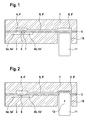
- Fig. 1 shows a schematic cross section through the first part of a first embodiment of a microfluidic device according to the invention in the form of a microvalve in the non-activated state.
- the illustrated microvalve comprises a first substrate 1, a second substrate 2, and a third substrate 3 disposed between the first substrate and the second substrate 3.
- the first and second substrates may be made of a thermoplastic, for example.
- the third substrate 3 is formed from an elastic material, in particular as a thermoplastic elastomer film, and, in particular sandwiched, disposed between the first substrate 1 and the second substrate 2.
- the first substrate 1 adjoins the third substrate 3 and has on the side adjacent to the third substrate a first recess 4, which forms a first control chamber 4 '.
- the second substrate 2 adjoins the third substrate 3 and has on the side adjacent to the third substrate 3 two recesses 5a and 5b, which form fluid channels or fluid chambers 5a 'and 5b' for the fluid to be handled.
- the recesses 5a and 5b are arranged adjacent and separated by a web 6, wherein both recesses 5a and 5b overlap at least partially with the first recess 4.
- it is a so-called "Narmally on" microvalve. This means that the microvalve, which is designed as a pinch valve in the illustrated embodiment, is in the non-activated state, ie at normal pressure in the first control chamber 4 'is open and by an increase in pressure in the first control chamber 4', as in Fig.
- FIG. 1 shown schematically, an increase in pressure of the fluid to be handled in the recess 5a causes the elastic substrate 3 in the first recess 4 expands and in this way allows a flow of the fluid to be handled from the recess 5a in the recess 5b (indicated by an arrow 7).
- a further recess 8 is provided in the first substrate 1, which forms a second control chamber 8 '.
- a fourth recess 9 is provided, which serves as a control channel 9 'and the first control chamber 4' with the second control chamber 8 'connects, so that the two control chambers 4' and 8 'together with the Control channel 9 'form a closed system
- Control chamber 8 ' has a larger internal volume than the first control chamber 4'.
- the control channel 8 ' is smaller in cross-section than the two control chambers 4' and 8 '.
- the two control chambers 4 'and 8' and the control channel 9 ' are filled with a control fluid, which may be made gaseous or liquid.
- air is used as the control fluid, since in this way a complex filling process of the two control chambers 4 'and 8' as well as of the control channel 9 'can be dispensed with.
- a passage opening 10 is provided, which is arranged exactly opposite the second control chamber 8 'in the illustrated embodiment.
- a mechanical activation member 11 for example in the form of a plunger, an actuator, not shown act on the elastic substrate 3 deformable.
- the elastic substrate 3 forms in the in the Figures 1 and 2 illustrated embodiment, an elastically deformable side wall of the second control chamber 8 '. If the mechanical activation member 11 of the actuator in the direction of arrow 12 ( FIG. 2 ) is pressed onto the elastic substrate 3, this is moved into the second control chamber 8 '.
- the through hole 10 is designed such that it has the same extent as the third recess 8 in the horizontal direction, ie in the direction parallel to the elastic substrate 3 and is arranged exactly opposite this recess 8.
- the passage opening 10 may also be displaced in a horizontal direction relative to the recess 9 and / or may also have a smaller or larger horizontal extent.
- the passage opening 10 at least partially overlaps with the recess 9, so that the activation member 11 can act on the elastic substrate 3 such that the elastic membrane 3 are pressed into the region of the third recess 8 can.
- the passage opening 10 is formed with respect to its horizontal extent such that it also serves as a guide for the activation member 11 of the actuator.
- FIG. 3 shows the first part of an alternative embodiment of a microfluidic device according to the invention, which analogous to the Figures 1 and 2 is designed as a microfluidic pinch valve.
- the elastic substrate 3 can not be used as an elastically deformable side wall of the second control chamber 8 '.
- a fifth recess 20 is provided in the first substrate 1, which is arranged on the side facing away from the third substrate 3 of the first substrate in such a way that it overlaps at least in partial areas with the second control chamber 8 '.
- the depth of the recess is determined such that a web-like region 21 of the first substrate 1 results between the fifth recess 20 and the second control chamber 8 ' on the one hand forms part of the outer wall of the first substrate 1, but on the other hand also serves as a deformable side wall of the second control chamber 8 '.
- an activation member 22 of an actuator can act on the web-like region 21 of the first substrate in such a way that the web-like region 21 is pressed into the region of the control chamber 8 '.
- the horizontal extent of the fifth recess 20 is greater than the horizontal extent of the third recess 8 executed. Also in this embodiment, alternatively, the horizontal extent of the fifth recess 20 may be equal to or smaller than the horizontal extent of the second control chamber 8 '.
- the fifth recess 20 overlaps at least partially with the third recess 8, so that the activation member 11 can act on the web-like region 21 of the first substrate 1 such that the web-like region 21 in the region the third recess 8 can be pressed.
- FIG. 4 shows the first part of a third embodiment of a microfluidic device according to the invention, which analogous to the FIGS. 1 to 3 is designed as a microfluidic pinch valve.
- no passage opening is provided in the second substrate 2, but only a sixth recess 30, which is arranged on the side facing away from the third substrate 3 of the second substrate 2 in such a way that they at least in some areas with the second control chamber 8 'overlaps.
- the depth of the recess is determined such that a web-like region 31 of the second substrate 2 results between the sixth recess 30 and the third substrate, which deforms Part of the outer wall of the second substrate 2 forms.
- An activation member 32 of an actuator can act on the web-like region 31 of the second substrate 2 such that the web-like region 31 in the direction of the third substrate 3 and thus the third substrate 3 in the region of the control chamber 8 'is pressed. This in turn leads to a reduction of the internal volume of the second control chamber 8 ', thereby increasing the pressure of the Steuerfuids and thus ultimately to a closing of the valve analogous to the embodiment already described.
- FIGS. 1 to 4 exemplified for a microfluidic pinch valve.
- the fluid channels or fluid chambers 5a and 5b and the first control chamber 4 ' By appropriate adjustments in terms of arrangement and design of the fluid channels or fluid chambers 5a and 5b and the first control chamber 4 ', it is readily possible for the skilled person to realize other valve designs or micropumps or micromixers.
- FIG. 5 schematically shows a perspective view of a non-inventive microfluidic chip 40, in particular a biochip, with a plurality of microfluidic devices 41a-f.
- the microfluidic components 41 ac are micropumps and the microfluidic components 41 df are microvalves.
- those fluid channels and fluid chambers that carry the fluid to be handled are shown with dashed lines.
- the chambers and channels guiding the control fluid are shown by solid lines.
- the possible by the microfluidic components according to the invention unbundling of the controlling elements of the elements to be controlled, ie the elements which carry the fluid to be handled, particularly clear.
- the second control chambers 8a 'to 8f on which the activators 42a-f of an actuator act are exemplarily disposed on the right side of the chip, whereas connections 43 for the fluid to be handled are provided on the opposite left side of the chip.
- suitable structuring of fluid channels 44, and fluid chambers 45 and the control channels 9a 'to 9f and first control chambers 4a' to 4f it is possible in this way, with constant positioning of the fluid connections and the points of attack for the activators of an actuator microfluidic chips with different wiring , So different arrangement and / or configuration of the arranged on the chip microfluidic devices to realize. In this way, a multiplicity of different microfluidic chips can be operated with a uniform operating device which receives an actuator.
- the actuator is designed such that it is loosely connected to the chip or a single microfluidic device, but also separable from this again.
- the chip can be realized as a disposable cartridge, which is the rule especially in the biotechnological and medical technology field of application.
- the actuators can be realized in the form of a reusable, in particular universally reusable operating device.
- the operating device can be, for example, battery-powered and operated independently of compressed air sources or air pumps.
- the actuators and their activation members can be made very diverse.
- a shaft 50 which optionally via an electric motor 51 in conjunction with translations, deflecting directions, levers or connecting rods.
- the shaft 50 can be provided with appropriately designed eccentrics, which serve as activators 42a-c.
- Such actuators can be used for example for micropumps with continuous or semi-continuous operation and in FIG. 5 exemplified as an actuator for the micropumps 41 a-c.
- an actuator can also have several activating members for the activation of several microfluidic components.
- magnetic actuators can be used, as in FIG. 5 are exemplified for the microvalves 41d-f. Magnetic actuators continue to allow a bistable use.
- FIG. 5 Such a designed actuator is in FIG. 5 shown schematically for the micro-valve 41 d.
- other actuator principles such as piezo actuators, also based on piezoelectric polymers, or electroactive polymers (EAP) settable.
- FIG. 5 also shows connections 43 'for a fluid to be handled and a possible impact area 46 of a further actuator, which are not used in the illustrated shading of the chip.
- the microfluidic component according to the invention additionally has a pressure compensation valve, which serves to equalize the pressure between the pneumatic system, consisting of the control chambers (4 ', 8') and the control channel (9 '), and the external environment.
- a pressure compensation valve which serves to equalize the pressure between the pneumatic system, consisting of the control chambers (4 ', 8') and the control channel (9 '), and the external environment.
- a pressure compensation valve is in the FIGS. 6 and 7 shown. It shows FIG. 6 a pressure compensation valve 60 in the open state and FIG. 7 the pressure compensation valve 60 in the closed state. To simplify the illustration is in the FIGS. 6 and 7 only the region of the microfluidic component shown, in which the pressure compensation valve is shown.
- the first substrate 1 has, on the side adjacent to the third substrate 3, two recesses 61a and 61b, which form fluid channels 61a 'and 61b' for the control fluid, ie for air.
- the recesses 61a and 61b are arranged adjacent thereto and separated by a web 62.
- a further recess 63 is provided, which is arranged on the third substrate 3 remote from the side of the second substrate 2 in such a way that it overlaps at least in partial areas with the two recesses 61 a and 61 b.
- the depth of the recess is determined such that a web-like region 64 of the second substrate 2 results between the further recess 63 and the third substrate, which forms a deformable part of the outer wall of the second substrate 2.
- An activation member 65 of an actuator can act on the web-like region 64 of the second substrate 2 such that the web-like region 64 in the direction of the third substrate 3 and thus the third substrate 3 is pressed onto the web 62 between the two recesses 61a and 61b. This in turn leads to a closing of the pressure compensation valve.
- the recess 61a is connected via a second pressure equalization channel 67 to the outside environment.
- the pressure compensation valve 60 can then be closed so that a reliable function is ensured.
- an elastic molding 68 e.g. in the form of an elastomeric pad.
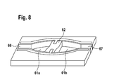
- the web 62 between the two recesses 61 a and 61 b can be made slightly curved (see FIG. 8 ).
- the curvature is designed such that the central region of the web has an increased distance from the third substrate 3 than the outer regions.
- the web 62 is formed concaved so far.
- a web 62 configured in this way can be connected to the first substrate 1, for example with the aid of welds 80.
- FIG. 9 schematically shows a perspective view of a microfluidic chip 90 similar to that according to FIG. 5 wherein additional pressure compensating valves 60a-f are provided, which are connected to the second control chambers 8a 'to 8f' via first pressure equalizing passages 66a-f and to the outside environment of the chip via second pressure compensating passages 67a-f.
- the webs 62a-f are indicated in the pressure compensation valves 60a-f, but which in one embodiment of the pressure compensation valves according to the FIGS. 6 and 7 due to the web-like region 64 of the second substrate 2 would not be visible in reality.
- one of the activation members 65 of the pressure compensation valve including an elastomeric pad 68 is also shown.
- the pressure compensation valve (60), the activation member (65) and the control unit are designed such that the pressure compensation valve (60) is automatically closed when inserted into the operating device. This can be achieved for example by using spring-loaded pins or permanently attached rubber buffer.
Landscapes
- Chemical & Material Sciences (AREA)
- Engineering & Computer Science (AREA)
- General Engineering & Computer Science (AREA)
- Dispersion Chemistry (AREA)
- Mechanical Engineering (AREA)
- Health & Medical Sciences (AREA)
- Analytical Chemistry (AREA)
- General Health & Medical Sciences (AREA)
- Hematology (AREA)
- Clinical Laboratory Science (AREA)
- Chemical Kinetics & Catalysis (AREA)
- Micromachines (AREA)
Claims (8)
- Elément structural micro-fluidique conçu pour la manipulation d'un fluide, en particulier micro-pompe, micro-soupape ou micro-mélangeur, avec un premier substrat (1), un deuxième substrat (2) et un troisième substrat (3) disposé entre le premier substrat (1) et le deuxième substrat (2), qui est constitué d'un matériau élastique, dans lequel- au moins un premier évidement (4), qui forme une première chambre de commande (4'), est pratiqué sur le côté du premier substrat (1) tourné vers le troisième substrat (3),- au moins un deuxième évidement (5a; 5b) est réalisé, qui forme un canal de fluide ou une chambre de fluide (5a'; 5b') pour le fluide à manipuler et qui est en recouvrement avec la première chambre de commande (4') au moins dans des régions partielles,- dans le premier substrat (1) sont réalisés une deuxième chambre de commande (8') spatialement séparée de la première chambre de commande (4') et un canal de commande (9'), qui relie la première chambre de commande (4') à la deuxième chambre de commande (8').- les chambres de commande (4', 8') et le canal de commande (9') sont remplis d'un fluide de commande, et- au moins une paroi latérale de la deuxième chambre de commande (8') est réalisée en matériau élastique et est déformable au moyen d'un actionneur, en particulier un organe d'activation mécanique (11) d'un actionneur, de telle manière que le volume intérieur de la deuxième chambre de commande (8') diminue,
caractérisé en ce que le deuxième évidement (5a; 5b) est pratiqué sur le côté du deuxième substrat (2) tourné vers le troisième substrat (3) et en ce qu'au moins un septième évidement (61a, 61b) est pratiqué sur le côté du premier substrat (1) tourné vers le troisième substrat (3) et forme une soupape d'équilibrage de pression, qui est reliée par un premier canal d'équilibrage de pression (66) à la première chambre de commande (4'), à la deuxième chambre de commande (8') ou au canal de commande (9') et qui est reliée par un deuxième canal d'équilibrage de pression (67) à l'environnement extérieur. - Elément structural micro-fluidique selon la revendication 1, dans lequel la deuxième chambre de commande (8') est formée par un troisième évidement (8), qui est pratiqué sur le côté du premier substrat (1) tourné vers le troisième substrat (3).
- Elément structural micro-fluidique selon la revendication 2, dans lequel le canal de commande (9') est formé par un quatrième évidement (9), qui est pratiqué sur le côté du premier substrat (1) tourné vers le troisième substrat (3) entre le premier évidement (4) et le troisième évidement (8).
- Elément structural micro-fluidique selon l'une quelconque des revendications précédentes, dans lequel la paroi latérale déformable de la deuxième chambre de commande (8') est formée par le troisième substrat (3).
- Elément structural micro-fluidique selon l'une quelconque des revendications 1 à 3, dans lequel la paroi latérale déformable de la deuxième chambre de commande (8') est formée par une paroi extérieure du premier substrat (1).
- Elément structural micro-fluidique selon l'une quelconque des revendications précédentes, dans lequel l'élément structural micro-fluidique peut être relié librement à l'actionneur.
- Elément structural micro-fluidique selon l'une quelconque des revendications précédentes, dans lequel l'actionneur est entraîné par voie électrique ou magnétique ou piézoélectrique ou par un polymère électro-actif.
- Puce micro-fluidique, en particulier biopuce, comprenant au moins un élément structural micro-fluidique selon l'une quelconque des revendications 1 à 7.
Applications Claiming Priority (2)
| Application Number | Priority Date | Filing Date | Title |
|---|---|---|---|
| DE102010001412A DE102010001412A1 (de) | 2010-02-01 | 2010-02-01 | Mikrofluidisches Bauelement zur Handhabung eines Fluids und mikrofluidischer Chip |
| PCT/EP2010/070908 WO2011091943A1 (fr) | 2010-02-01 | 2010-12-30 | Elément structural microfluidique conçu pour la manipulation d'un fluide et puce microfluidique |
Publications (2)
| Publication Number | Publication Date |
|---|---|
| EP2531760A1 EP2531760A1 (fr) | 2012-12-12 |
| EP2531760B1 true EP2531760B1 (fr) | 2015-07-15 |
Family
ID=43735759
Family Applications (1)
| Application Number | Title | Priority Date | Filing Date |
|---|---|---|---|
| EP10800958.0A Active EP2531760B1 (fr) | 2010-02-01 | 2010-12-30 | Elément structural microfluidique conçu pour la manipulation d'un fluide et puce microfluidique |
Country Status (5)
| Country | Link |
|---|---|
| US (1) | US20120298233A1 (fr) |
| EP (1) | EP2531760B1 (fr) |
| CN (1) | CN102713389B (fr) |
| DE (1) | DE102010001412A1 (fr) |
| WO (1) | WO2011091943A1 (fr) |
Families Citing this family (28)
| Publication number | Priority date | Publication date | Assignee | Title |
|---|---|---|---|---|
| US9188243B2 (en) * | 2010-01-29 | 2015-11-17 | The Trustees Of Columbia University In The City Of New York | Microfluidic flow devices, methods and systems |
| WO2012091677A1 (fr) * | 2010-12-30 | 2012-07-05 | Agency For Science, Technology And Research | Module de soupape microfluidique et système pour mise en œuvre |
| US20120181460A1 (en) * | 2011-01-14 | 2012-07-19 | Integenx Inc. | Valves with Hydraulic Actuation System |
| DE102011078976A1 (de) * | 2011-07-11 | 2013-01-17 | Robert Bosch Gmbh | Mikrofluidische Vorrichtung sowie Verfahren zur Herstellung einer mikrofluidischen Vorrichtung |
| JP6357217B2 (ja) * | 2011-07-25 | 2018-07-11 | 株式会社エンプラス | 流体取扱装置および流体取扱方法 |
| CN103157523A (zh) * | 2011-12-15 | 2013-06-19 | 三星电子株式会社 | 微流器件及其制造方法 |
| CN102679039A (zh) * | 2012-05-07 | 2012-09-19 | 博奥生物有限公司 | 一种集成于微流控芯片内的气动微阀 |
| WO2013166856A1 (fr) * | 2012-05-07 | 2013-11-14 | Capitalbio Corporation | Micro-soupape intégrée dans un dispositif microfluidique et son procédé d'utilisation |
| DE102012212650A1 (de) * | 2012-07-19 | 2014-01-23 | Robert Bosch Gmbh | Mikrofluidische Lagerungsvorrichtung zum Vorlagern eines Fluids, Verfahren zu dessen Herstellung und eine Verwendung derselben |
| CN102797872B (zh) * | 2012-09-01 | 2014-01-15 | 安徽理工大学 | 一种基于超磁致伸缩薄膜驱动器的平面线圈驱动式微阀 |
| DE102013207193A1 (de) * | 2013-04-22 | 2014-10-23 | Robert Bosch Gmbh | Mikrohydraulisches System, insbesondere zum Einsatz in planaren Mikrofluidiklaboren |
| US20160319958A1 (en) * | 2013-12-11 | 2016-11-03 | Ikerlan, S. Coop | Multiplexed valve for microfluidic devices |
| CN103801415A (zh) * | 2014-03-12 | 2014-05-21 | 杭州霆科生物科技有限公司 | 一种按钮式微流体控制系统及方法 |
| CN105370917B (zh) * | 2014-08-19 | 2017-10-31 | 清华大学 | 一种用于微流体控制的微流体控制阀 |
| DE102015226417A1 (de) | 2015-12-22 | 2017-06-22 | Robert Bosch Gmbh | Mikrofluidische Vorrichtung, Verfahren zum Herstellen und Verfahren zum Betreiben einer mikrofluidischen Vorrichtung |
| TWI789343B (zh) | 2016-02-01 | 2023-01-11 | 丹麥商碩騰丹麥有限公司 | 微流體分析系統、執行分析的微流體匣及方法 |
| US11161111B2 (en) * | 2016-06-29 | 2021-11-02 | Miltenyi Biotec B. V. & Co. KG | Multilevel disposable cartridge for biological specimens |
| US10682644B2 (en) | 2016-10-07 | 2020-06-16 | Boehringer Ingelheim Vetmedica Gmbh | Cartridge, analysis system and method for testing a sample |
| US11213824B2 (en) | 2017-03-29 | 2022-01-04 | The Research Foundation For The State University Of New York | Microfluidic device and methods |
| US11364496B2 (en) | 2017-04-21 | 2022-06-21 | Hewlett-Packard Development Company, L.P. | Coplanar fluidic interconnect |
| WO2018194635A1 (fr) * | 2017-04-21 | 2018-10-25 | Hewlett-Packard Development Company, L.P. | Interconnexion fluidique de puce à puce |
| EP3582892A4 (fr) | 2017-04-21 | 2020-03-04 | Hewlett-Packard Development Company, L.P. | Manipulation microfluidique coplanaire |
| US11278887B2 (en) | 2017-04-21 | 2022-03-22 | Hewlett-Packard Development Company, L.P. | Microfluidic chip |
| CN109603942B (zh) * | 2019-02-15 | 2021-12-24 | 京东方科技集团股份有限公司 | 微流控装置和微流控方法 |
| US11236846B1 (en) * | 2019-07-11 | 2022-02-01 | Facebook Technologies, Llc | Fluidic control: using exhaust as a control mechanism |
| EP3763439A1 (fr) * | 2019-07-12 | 2021-01-13 | Curiosity Diagnostics sp. z o.o | Puce et soupape microfluidiques, procédé de production et utilisations |
| CN111013675A (zh) * | 2019-12-11 | 2020-04-17 | 北京柏兆嘉业科技有限公司 | 微流控盘片及基于免洗微流控技术进行甲状腺功能测定的方法 |
| CN112337516B (zh) * | 2020-09-18 | 2022-04-29 | 东莞东阳光医疗智能器件研发有限公司 | 气压平衡微流控芯片及其控制方法 |
Family Cites Families (7)
| Publication number | Priority date | Publication date | Assignee | Title |
|---|---|---|---|---|
| US6129331A (en) * | 1997-05-21 | 2000-10-10 | Redwood Microsystems | Low-power thermopneumatic microvalve |
| DE60103924T2 (de) * | 2000-11-06 | 2005-07-14 | Nanostream, Inc., Pasadena | Mikrofluidische durchflussregelvorrichtung |
| WO2004061085A2 (fr) * | 2002-12-30 | 2004-07-22 | The Regents Of The University Of California | Procedes et appareil pour la detection et l'analyse d'agents pathogenes |
| US20090165876A1 (en) * | 2005-11-22 | 2009-07-02 | Micah James Atkin | Microfluidic Structures |
| US20080135114A1 (en) * | 2006-08-02 | 2008-06-12 | The Regents Of The University Of Michigan | Multiplexed Hydraulic Valve Actuation Devices And Methods |
| US8016260B2 (en) * | 2007-07-19 | 2011-09-13 | Formulatrix, Inc. | Metering assembly and method of dispensing fluid |
| DE102008002336A1 (de) | 2008-06-10 | 2009-12-24 | Robert Bosch Gmbh | Quetschventil und Verfahren zu dessen Herstellung |
-
2010
- 2010-02-01 DE DE102010001412A patent/DE102010001412A1/de not_active Withdrawn
- 2010-12-30 EP EP10800958.0A patent/EP2531760B1/fr active Active
- 2010-12-30 US US13/576,415 patent/US20120298233A1/en not_active Abandoned
- 2010-12-30 WO PCT/EP2010/070908 patent/WO2011091943A1/fr active Application Filing
- 2010-12-30 CN CN201080062847.2A patent/CN102713389B/zh active Active
Also Published As
| Publication number | Publication date |
|---|---|
| DE102010001412A1 (de) | 2011-08-04 |
| CN102713389B (zh) | 2014-05-07 |
| WO2011091943A1 (fr) | 2011-08-04 |
| CN102713389A (zh) | 2012-10-03 |
| EP2531760A1 (fr) | 2012-12-12 |
| US20120298233A1 (en) | 2012-11-29 |
Similar Documents
| Publication | Publication Date | Title |
|---|---|---|
| EP2531760B1 (fr) | Elément structural microfluidique conçu pour la manipulation d'un fluide et puce microfluidique | |
| DE102007035721B4 (de) | Mikroventil, Verfahren zum Herstellen eines Mikroventils sowie Mikropumpe | |
| DE10048376C2 (de) | Mikroventil mit einem normalerweise geschlossenen Zustand | |
| EP1458977B2 (fr) | Micropompe peristaltique | |
| EP0478565B1 (fr) | Micro-soupape | |
| EP2686595B1 (fr) | Soupape micro-fluidique et plateforme micro-fluidique | |
| EP2731721B1 (fr) | Dispositif microfluidique et procédé de production d'un dispositif microfluidique | |
| WO2009052842A1 (fr) | Pompe à membrane | |
| WO2009156103A1 (fr) | Microvanne et dispositif d'étanchéité destinés à un microsystème fluidique, ainsi que son procédé de fabrication | |
| EP3406340B1 (fr) | Cellule d'écoulement comprenant un élément de boîtier | |
| EP1576294B1 (fr) | Microvanne normalement doublement fermee | |
| DE4138491A1 (de) | Mikromechanisches ventil fuer mikromechanische dosiereinrichtungen | |
| EP2567092B1 (fr) | Elément microfluidique, en particulier micropompe péristaltique, et son procédé de réalisation | |
| EP2730335A1 (fr) | Pompe péristaltique microfluidique, procédé et système de pompe | |
| DE102016106909A1 (de) | Elektropneumatische Ventilgruppe | |
| DE102008056751A1 (de) | Fluidikvorrichtung mit normal-geschlossener Durchlassöffnung | |
| DE102008004147A1 (de) | Mikropumpe und Verfahren zum Pumpen eines Fluids | |
| EP2754495A2 (fr) | Système de canaux microfluidique doté d'un dispositif de collecte de bulles et procédé d'élimination de bulles de gaz | |
| EP3861238B1 (fr) | Microsoupape hydraulique | |
| EP2833042A1 (fr) | Agencement de soupape destiné à commuter et/ou régler un flux de milieu d'un propulseur spatial et propulseur spatial | |
| DE19844518A1 (de) | Hydraulischer Wegverstärker für Mikrosysteme | |
| EP2688671B1 (fr) | Dispositif de fabrication d'une liaison fluidique entre cavités | |
| DE102013207193A1 (de) | Mikrohydraulisches System, insbesondere zum Einsatz in planaren Mikrofluidiklaboren | |
| DE102009001115A1 (de) | Mikroventil | |
| DE112004002936T5 (de) | Ventilschieber fuer ein mikrofluidisches Kopplungsgerät |
Legal Events
| Date | Code | Title | Description |
|---|---|---|---|
| PUAI | Public reference made under article 153(3) epc to a published international application that has entered the european phase |
Free format text: ORIGINAL CODE: 0009012 |
|
| 17P | Request for examination filed |
Effective date: 20120903 |
|
| AK | Designated contracting states |
Kind code of ref document: A1 Designated state(s): AL AT BE BG CH CY CZ DE DK EE ES FI FR GB GR HR HU IE IS IT LI LT LU LV MC MK MT NL NO PL PT RO RS SE SI SK SM TR |
|
| DAX | Request for extension of the european patent (deleted) | ||
| GRAP | Despatch of communication of intention to grant a patent |
Free format text: ORIGINAL CODE: EPIDOSNIGR1 |
|
| INTG | Intention to grant announced |
Effective date: 20150129 |
|
| GRAS | Grant fee paid |
Free format text: ORIGINAL CODE: EPIDOSNIGR3 |
|
| GRAA | (expected) grant |
Free format text: ORIGINAL CODE: 0009210 |
|
| AK | Designated contracting states |
Kind code of ref document: B1 Designated state(s): AL AT BE BG CH CY CZ DE DK EE ES FI FR GB GR HR HU IE IS IT LI LT LU LV MC MK MT NL NO PL PT RO RS SE SI SK SM TR |
|
| REG | Reference to a national code |
Ref country code: CH Ref legal event code: EP Ref country code: GB Ref legal event code: FG4D Free format text: NOT ENGLISH |
|
| REG | Reference to a national code |
Ref country code: IE Ref legal event code: FG4D Free format text: LANGUAGE OF EP DOCUMENT: GERMAN |
|
| REG | Reference to a national code |
Ref country code: AT Ref legal event code: REF Ref document number: 736973 Country of ref document: AT Kind code of ref document: T Effective date: 20150815 |
|
| REG | Reference to a national code |
Ref country code: DE Ref legal event code: R096 Ref document number: 502010009871 Country of ref document: DE |
|
| REG | Reference to a national code |
Ref country code: FR Ref legal event code: PLFP Year of fee payment: 6 |
|
| REG | Reference to a national code |
Ref country code: NL Ref legal event code: FP |
|
| REG | Reference to a national code |
Ref country code: LT Ref legal event code: MG4D |
|
| PG25 | Lapsed in a contracting state [announced via postgrant information from national office to epo] |
Ref country code: NO Free format text: LAPSE BECAUSE OF FAILURE TO SUBMIT A TRANSLATION OF THE DESCRIPTION OR TO PAY THE FEE WITHIN THE PRESCRIBED TIME-LIMIT Effective date: 20151015 Ref country code: FI Free format text: LAPSE BECAUSE OF FAILURE TO SUBMIT A TRANSLATION OF THE DESCRIPTION OR TO PAY THE FEE WITHIN THE PRESCRIBED TIME-LIMIT Effective date: 20150715 Ref country code: LV Free format text: LAPSE BECAUSE OF FAILURE TO SUBMIT A TRANSLATION OF THE DESCRIPTION OR TO PAY THE FEE WITHIN THE PRESCRIBED TIME-LIMIT Effective date: 20150715 Ref country code: LT Free format text: LAPSE BECAUSE OF FAILURE TO SUBMIT A TRANSLATION OF THE DESCRIPTION OR TO PAY THE FEE WITHIN THE PRESCRIBED TIME-LIMIT Effective date: 20150715 Ref country code: GR Free format text: LAPSE BECAUSE OF FAILURE TO SUBMIT A TRANSLATION OF THE DESCRIPTION OR TO PAY THE FEE WITHIN THE PRESCRIBED TIME-LIMIT Effective date: 20151016 |
|
| PG25 | Lapsed in a contracting state [announced via postgrant information from national office to epo] |
Ref country code: HR Free format text: LAPSE BECAUSE OF FAILURE TO SUBMIT A TRANSLATION OF THE DESCRIPTION OR TO PAY THE FEE WITHIN THE PRESCRIBED TIME-LIMIT Effective date: 20150715 Ref country code: RS Free format text: LAPSE BECAUSE OF FAILURE TO SUBMIT A TRANSLATION OF THE DESCRIPTION OR TO PAY THE FEE WITHIN THE PRESCRIBED TIME-LIMIT Effective date: 20150715 Ref country code: ES Free format text: LAPSE BECAUSE OF FAILURE TO SUBMIT A TRANSLATION OF THE DESCRIPTION OR TO PAY THE FEE WITHIN THE PRESCRIBED TIME-LIMIT Effective date: 20150715 Ref country code: PT Free format text: LAPSE BECAUSE OF FAILURE TO SUBMIT A TRANSLATION OF THE DESCRIPTION OR TO PAY THE FEE WITHIN THE PRESCRIBED TIME-LIMIT Effective date: 20151116 Ref country code: PL Free format text: LAPSE BECAUSE OF FAILURE TO SUBMIT A TRANSLATION OF THE DESCRIPTION OR TO PAY THE FEE WITHIN THE PRESCRIBED TIME-LIMIT Effective date: 20150715 Ref country code: SE Free format text: LAPSE BECAUSE OF FAILURE TO SUBMIT A TRANSLATION OF THE DESCRIPTION OR TO PAY THE FEE WITHIN THE PRESCRIBED TIME-LIMIT Effective date: 20150715 |
|
| REG | Reference to a national code |
Ref country code: DE Ref legal event code: R097 Ref document number: 502010009871 Country of ref document: DE |
|
| PG25 | Lapsed in a contracting state [announced via postgrant information from national office to epo] |
Ref country code: SK Free format text: LAPSE BECAUSE OF FAILURE TO SUBMIT A TRANSLATION OF THE DESCRIPTION OR TO PAY THE FEE WITHIN THE PRESCRIBED TIME-LIMIT Effective date: 20150715 Ref country code: EE Free format text: LAPSE BECAUSE OF FAILURE TO SUBMIT A TRANSLATION OF THE DESCRIPTION OR TO PAY THE FEE WITHIN THE PRESCRIBED TIME-LIMIT Effective date: 20150715 Ref country code: CZ Free format text: LAPSE BECAUSE OF FAILURE TO SUBMIT A TRANSLATION OF THE DESCRIPTION OR TO PAY THE FEE WITHIN THE PRESCRIBED TIME-LIMIT Effective date: 20150715 Ref country code: DK Free format text: LAPSE BECAUSE OF FAILURE TO SUBMIT A TRANSLATION OF THE DESCRIPTION OR TO PAY THE FEE WITHIN THE PRESCRIBED TIME-LIMIT Effective date: 20150715 |
|
| PLBE | No opposition filed within time limit |
Free format text: ORIGINAL CODE: 0009261 |
|
| STAA | Information on the status of an ep patent application or granted ep patent |
Free format text: STATUS: NO OPPOSITION FILED WITHIN TIME LIMIT |
|
| PG25 | Lapsed in a contracting state [announced via postgrant information from national office to epo] |
Ref country code: RO Free format text: LAPSE BECAUSE OF FAILURE TO SUBMIT A TRANSLATION OF THE DESCRIPTION OR TO PAY THE FEE WITHIN THE PRESCRIBED TIME-LIMIT Effective date: 20150715 Ref country code: BE Free format text: LAPSE BECAUSE OF NON-PAYMENT OF DUE FEES Effective date: 20151231 |
|
| 26N | No opposition filed |
Effective date: 20160418 |
|
| PG25 | Lapsed in a contracting state [announced via postgrant information from national office to epo] |
Ref country code: IS Free format text: LAPSE BECAUSE OF FAILURE TO SUBMIT A TRANSLATION OF THE DESCRIPTION OR TO PAY THE FEE WITHIN THE PRESCRIBED TIME-LIMIT Effective date: 20150715 |
|
| PG25 | Lapsed in a contracting state [announced via postgrant information from national office to epo] |
Ref country code: LU Free format text: LAPSE BECAUSE OF FAILURE TO SUBMIT A TRANSLATION OF THE DESCRIPTION OR TO PAY THE FEE WITHIN THE PRESCRIBED TIME-LIMIT Effective date: 20151230 Ref country code: MC Free format text: LAPSE BECAUSE OF FAILURE TO SUBMIT A TRANSLATION OF THE DESCRIPTION OR TO PAY THE FEE WITHIN THE PRESCRIBED TIME-LIMIT Effective date: 20150715 |
|
| REG | Reference to a national code |
Ref country code: CH Ref legal event code: PL |
|
| PG25 | Lapsed in a contracting state [announced via postgrant information from national office to epo] |
Ref country code: SI Free format text: LAPSE BECAUSE OF FAILURE TO SUBMIT A TRANSLATION OF THE DESCRIPTION OR TO PAY THE FEE WITHIN THE PRESCRIBED TIME-LIMIT Effective date: 20150715 |
|
| REG | Reference to a national code |
Ref country code: IE Ref legal event code: MM4A |
|
| PG25 | Lapsed in a contracting state [announced via postgrant information from national office to epo] |
Ref country code: CH Free format text: LAPSE BECAUSE OF NON-PAYMENT OF DUE FEES Effective date: 20151231 Ref country code: IE Free format text: LAPSE BECAUSE OF NON-PAYMENT OF DUE FEES Effective date: 20151230 Ref country code: LI Free format text: LAPSE BECAUSE OF NON-PAYMENT OF DUE FEES Effective date: 20151231 |
|
| REG | Reference to a national code |
Ref country code: FR Ref legal event code: PLFP Year of fee payment: 7 |
|
| REG | Reference to a national code |
Ref country code: AT Ref legal event code: MM01 Ref document number: 736973 Country of ref document: AT Kind code of ref document: T Effective date: 20151230 |
|
| PG25 | Lapsed in a contracting state [announced via postgrant information from national office to epo] |
Ref country code: HU Free format text: LAPSE BECAUSE OF FAILURE TO SUBMIT A TRANSLATION OF THE DESCRIPTION OR TO PAY THE FEE WITHIN THE PRESCRIBED TIME-LIMIT; INVALID AB INITIO Effective date: 20101230 Ref country code: AT Free format text: LAPSE BECAUSE OF NON-PAYMENT OF DUE FEES Effective date: 20151230 Ref country code: SM Free format text: LAPSE BECAUSE OF FAILURE TO SUBMIT A TRANSLATION OF THE DESCRIPTION OR TO PAY THE FEE WITHIN THE PRESCRIBED TIME-LIMIT Effective date: 20150715 Ref country code: BG Free format text: LAPSE BECAUSE OF FAILURE TO SUBMIT A TRANSLATION OF THE DESCRIPTION OR TO PAY THE FEE WITHIN THE PRESCRIBED TIME-LIMIT Effective date: 20150715 |
|
| PG25 | Lapsed in a contracting state [announced via postgrant information from national office to epo] |
Ref country code: CY Free format text: LAPSE BECAUSE OF FAILURE TO SUBMIT A TRANSLATION OF THE DESCRIPTION OR TO PAY THE FEE WITHIN THE PRESCRIBED TIME-LIMIT Effective date: 20150715 |
|
| PG25 | Lapsed in a contracting state [announced via postgrant information from national office to epo] |
Ref country code: MT Free format text: LAPSE BECAUSE OF FAILURE TO SUBMIT A TRANSLATION OF THE DESCRIPTION OR TO PAY THE FEE WITHIN THE PRESCRIBED TIME-LIMIT Effective date: 20150715 |
|
| REG | Reference to a national code |
Ref country code: FR Ref legal event code: PLFP Year of fee payment: 8 |
|
| PG25 | Lapsed in a contracting state [announced via postgrant information from national office to epo] |
Ref country code: TR Free format text: LAPSE BECAUSE OF FAILURE TO SUBMIT A TRANSLATION OF THE DESCRIPTION OR TO PAY THE FEE WITHIN THE PRESCRIBED TIME-LIMIT Effective date: 20150715 Ref country code: MK Free format text: LAPSE BECAUSE OF FAILURE TO SUBMIT A TRANSLATION OF THE DESCRIPTION OR TO PAY THE FEE WITHIN THE PRESCRIBED TIME-LIMIT Effective date: 20150715 |
|
| PG25 | Lapsed in a contracting state [announced via postgrant information from national office to epo] |
Ref country code: AL Free format text: LAPSE BECAUSE OF FAILURE TO SUBMIT A TRANSLATION OF THE DESCRIPTION OR TO PAY THE FEE WITHIN THE PRESCRIBED TIME-LIMIT Effective date: 20150715 |
|
| PGFP | Annual fee paid to national office [announced via postgrant information from national office to epo] |
Ref country code: NL Payment date: 20201217 Year of fee payment: 11 |
|
| PGFP | Annual fee paid to national office [announced via postgrant information from national office to epo] |
Ref country code: IT Payment date: 20201230 Year of fee payment: 11 |
|
| REG | Reference to a national code |
Ref country code: NL Ref legal event code: MM Effective date: 20220101 |
|
| PG25 | Lapsed in a contracting state [announced via postgrant information from national office to epo] |
Ref country code: NL Free format text: LAPSE BECAUSE OF NON-PAYMENT OF DUE FEES Effective date: 20220101 |
|
| PG25 | Lapsed in a contracting state [announced via postgrant information from national office to epo] |
Ref country code: IT Free format text: LAPSE BECAUSE OF NON-PAYMENT OF DUE FEES Effective date: 20211230 |
|
| PGFP | Annual fee paid to national office [announced via postgrant information from national office to epo] |
Ref country code: DE Payment date: 20230223 Year of fee payment: 13 |
|
| PGFP | Annual fee paid to national office [announced via postgrant information from national office to epo] |
Ref country code: GB Payment date: 20231220 Year of fee payment: 14 |
|
| PGFP | Annual fee paid to national office [announced via postgrant information from national office to epo] |
Ref country code: FR Payment date: 20231219 Year of fee payment: 14 |