EP2529849A2 - Device and method for manufacturing slot pipes made of sheet panels - Google Patents
Device and method for manufacturing slot pipes made of sheet panels Download PDFInfo
- Publication number
- EP2529849A2 EP2529849A2 EP12003900A EP12003900A EP2529849A2 EP 2529849 A2 EP2529849 A2 EP 2529849A2 EP 12003900 A EP12003900 A EP 12003900A EP 12003900 A EP12003900 A EP 12003900A EP 2529849 A2 EP2529849 A2 EP 2529849A2
- Authority
- EP
- European Patent Office
- Prior art keywords
- preform
- tube
- bending
- slot
- tool
- Prior art date
- Legal status (The legal status is an assumption and is not a legal conclusion. Google has not performed a legal analysis and makes no representation as to the accuracy of the status listed.)
- Granted
Links
Images


Classifications
-
- B—PERFORMING OPERATIONS; TRANSPORTING
- B21—MECHANICAL METAL-WORKING WITHOUT ESSENTIALLY REMOVING MATERIAL; PUNCHING METAL
- B21D—WORKING OR PROCESSING OF SHEET METAL OR METAL TUBES, RODS OR PROFILES WITHOUT ESSENTIALLY REMOVING MATERIAL; PUNCHING METAL
- B21D5/00—Bending sheet metal along straight lines, e.g. to form simple curves
- B21D5/01—Bending sheet metal along straight lines, e.g. to form simple curves between rams and anvils or abutments
- B21D5/015—Bending sheet metal along straight lines, e.g. to form simple curves between rams and anvils or abutments for making tubes
-
- B—PERFORMING OPERATIONS; TRANSPORTING
- B21—MECHANICAL METAL-WORKING WITHOUT ESSENTIALLY REMOVING MATERIAL; PUNCHING METAL
- B21C—MANUFACTURE OF METAL SHEETS, WIRE, RODS, TUBES OR PROFILES, OTHERWISE THAN BY ROLLING; AUXILIARY OPERATIONS USED IN CONNECTION WITH METAL-WORKING WITHOUT ESSENTIALLY REMOVING MATERIAL
- B21C37/00—Manufacture of metal sheets, bars, wire, tubes or like semi-manufactured products, not otherwise provided for; Manufacture of tubes of special shape
- B21C37/06—Manufacture of metal sheets, bars, wire, tubes or like semi-manufactured products, not otherwise provided for; Manufacture of tubes of special shape of tubes or metal hoses; Combined procedures for making tubes, e.g. for making multi-wall tubes
- B21C37/08—Making tubes with welded or soldered seams
- B21C37/0815—Making tubes with welded or soldered seams without continuous longitudinal movement of the sheet during the bending operation
Definitions
- the invention relates to a method for producing slotted tubes from sheet metal plates, in particular thick metal sheets, wherein a metal sheet is fed to a tube forming press in which it rests on a lower tool of a raised and lowered upper tool by applying a bending force progressively to the later Lhacksnahtsch spaung With a gap opposite longitudinal edges having slot tube is formed. Furthermore, the invention relates to a device for carrying out the method.
- a pipe forming or tube bending press has usually in a base frame one of two laterally spaced juxtaposed support or bending bodies existing lower tool and a vertically engageable from above against the lower die, carried by a raisable and lowerable bending bar, over the entire length the metal sheet extending upper tool with which a bending force can be applied to the resting on the lower die metal sheet.
- the Metal sheet is pre-bent at the longitudinal edges in a first step, usually in a separate edge banding press.
- the pre-bending of the longitudinal edges is carried out so that the tube radius in the deformation of the slot tube in the region of the later seam, where the longitudinal edges of the bent to the tube sheet metal plate face each other for Leksnahtversch adoptedung with a gap is uniformly formed.
- the thus pre-bent metal sheet is then inserted into the pipe-forming press and subjected there to the actual bending process.
- a bending force is applied to the metal sheet by depressing the press upper part, which sets a deformation of the metal sheet under the action of the bending load value and carried by this upper mold. This procedure is repeated several times until the metal sheet has been converted to the slot pipe.
- a very problematic in the progressive molding process has a significantly influenced by the sword width, especially in thick-walled tubes, for example, 40 mm remaining, large residual gap of the slot of about 130 to 170 mm and also shown stresses in the slot tube.
- a Large slit width requires high closing forces in the tack welding device, and because of the high stresses in the stapled as well as residual stresses in the finished welded pipe there is a risk of a rupturing tack or weld.
- When recognized too large slot widths remedy is created by the fact that experienced machine operators have closed by repeated manual actuation of the tube forming press the slot as far as possible. This procedure is not only time consuming with correspondingly reduced throughput, but continue to perform not with reproducible good quality.
- the invention is therefore an object of the invention to provide a method and a system of the type mentioned without the disadvantages mentioned, especially in thick-walled and small in diameter, for example, about 800 mm, tubes in a simple way the production of circular cylindrical slotted tubes with reproducible quality create.
- a slot tube is produced with a non-circular preform by at least in a relative to the dipping of the longitudinal axis of the progressively formed metal sheet upper tool center respectively left and right on the inside of the metal sheet acting bending step is compared to the other Biezogen lower indentation is made, and that thereafter by applying an externally on the non-circular preform each targeted in the previously on both sides of the middle of small molded areas impacting Zudrückkraft the finished slot tube is formed.
- An advantageous measure according to the invention provides that the non-circular preform is positioned in the finishing step before applying the Zudrückkraft by rotation in a clockwise or counterclockwise direction. Depending on the positioning, the compression force is thus introduced to the left or right of the slot or gap in the non-circular preform.
- the area of the lower half formed on the right side of the center is turned to an approximately 3 o'clock position and the area of the lower left of the center is turned to an approximately 9 o'clock position.
- the object underlying the invention is achieved with a device that is provided for forming the metal sheet to a non-circular preform and then reshaping to the slotted tube with reversible in their rotation means formed lower tool and externally acted upon against the positioned preform punch.
- the finished slot tube can thus be produced starting from the metal sheet on only one tube forming press or machine.
- the reversal of the direction of rotation allows the non-circular preform to be positioned exactly in such a way that the compressive force acts at the point of action, namely on both sides of the slot. It can readily be used to apply the Zudschreibkraft from the outside to the preform, the bending rate of the tube forming press.
- the press can be converted with a Zudschreibstempel.
- An embodiment of the invention which is preferred for increasing the production output provides that at least one tube forming press producing a noncircular preform is followed by a pressing press, which has the lower tool formed with means reversible in its direction of rotation and, as upper tool, the punch which can be acted on from the outside against the positioned non-circular preform.
- the tube forming press from which the non-circular shape is ejected, thus closes a pressing press, in which the supplied non-circular preform is formed into the finished slot tube at least in two successive steps, respectively to the right and left of the slot or gap ,
- the non-circular preforming of the metal sheet can thus be carried out at a location independent of the final deformation of the slot pipe.
- the rotatable means of the lower tool are formed according to a proposal of the invention as two spaced-apart, rotatably driven rollers. Reversing the direction of rotation of the rollers makes it possible to position the non-circular preform for final forming with optimized force introduction.
- the time course on the one hand in the preforming in the tube forming press and on the other hand the completion in the Zudschreibpresse allows that a downstream Zudschreibpresse can serve two tube forming presses.
- An embodiment of the invention provides that the rotatable rollers are mounted with a suspension.
- the support of the non-round preform on the lower tool of the Zudrückpresse can be improved by a provided between the rollers, stationary support body.
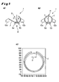
- a well-known tube forming press 1 is after Fig. 1 one on their long sides with edge bends 2 (see. Fig. 3 ) provided sheet metal plate 3 gradually to a finished slotted tube 4 a - or reshaped.
- the metal sheet 3 is placed on a two spaced-apart support body 5a, 5b having lower tool 6, wherein the forming force of a bending spring 7 with a mounted on his leading front end mold 8, raised and lowered upper tool 9 is applied.
- the metal sheet 3 to be formed or formed is guided by two lateral counter-supports 10a, 10b, of which the counter-holder 10a is linearly adjustable and nachschiebt the required for a next Einform suits sheet metal section.
- the finished slot pipe 4, as in Fig. 1c illustrates, has a large slot or gap 11, the welding to a closed, longitudinally welded pipe, as shown in dashed lines in Fig. 1c shown, extremely difficult.
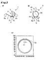
- the non-circular preform 13 thus produced in a first stage in the tube-forming press 1 is fed from the tube-forming press 1 to a pressure-feeding press 14 which is connected downstream in the production process after the conveying out or pushing Fig. 2b shown.
- the Zudschreibpresse 14 has a lower tool 15, which consists of two spaced-apart, reversible in their direction of rotation, as in Fig. 2b indicated by the double arrows, driven rollers 16a, 16b and a distance between the rollers 16a, 16b bridging, stationary support body 17 is made.
- the rotatable rollers 16a, 16b can be supported supported by a spring means 18 (see. Fig. 3 ).
- the lower tool 15 opposite a formed with a punch 19 upper tool 20 is arranged. About the punch 19, the Zudschreibkraft for producing the finished, largely circular slot tube 104 is applied from the outside to the non-circular preform 13.
- the non-circular preform 13 is positioned over the rotatable rollers 16a, 16b so that the less molded portion 12b located to the right of the slit 11 is in a 3 o'clock position as in FIG Fig. 3 indicated by the dot-dashed, horizontal line.
- the second press bending step is - in the same sequence as before - in Fig. 4B illustrated.
- the preform 13 which is still non-circular in its left half, has been positioned such that the area 12a, which is formed less to the left of the slot or gap 11, assumes a 9 o'clock position.
- the applied by the punch 19 now on this side of the preform 13 Zudschreibkraft F brings the non-circular preform 13 then in the final, largely circular shape of the finished slot tube 104 with the achieved thereby, much smaller slit or gap 111 (Fig. Right outside).
Abstract
Description
Die Erfindung betrifft ein Verfahren zum Herstellen von Schlitzrohren aus Blechtafeln, insbesondere dicken Blechtafeln, wobei eine Blechtafel einer Rohrformpresse zugeführt wird, in der sie auf einem Unterwerkzeug aufliegend von einem heb- und senkbaren Oberwerkzeug durch Aufbringung einer Biegekraft fortschreitend zu dem sich zu einer späteren Längsnahtschweißung mit einem Spalt gegenüberliegende Längskanten aufweisenden Schlitzrohr eingeformt wird. Weiterhin betrifft die Erfindung eine Vorrichtung zum Durchführen des Verfahrens.The invention relates to a method for producing slotted tubes from sheet metal plates, in particular thick metal sheets, wherein a metal sheet is fed to a tube forming press in which it rests on a lower tool of a raised and lowered upper tool by applying a bending force progressively to the later Längsnahtschweißung With a gap opposite longitudinal edges having slot tube is formed. Furthermore, the invention relates to a device for carrying out the method.
Zu dem in der Praxis angewendeten Verfahren zur Herstellung von Rohren aus Blechtafeln zählt das Rohrformpressverfahren mit fortschreitenden Einform- bzw. Biegeschritten auf Rohrformpressen. Eine Rohrform- bzw. Rohrbiegepresse besitzt üblich in einem Grundrahmen ein aus zwei in seitlichem Abstand nebeneinander angeordneten Stütz- bzw. Biegekörpern bestehendes Unterwerkzeug und ein vertikal von oben gegen das Unterwerkzeug anstellbares, von einem heb- und senkbaren Biegeschwert getragenes, sich über die gesamte Länge der Blechtafel erstreckendes Oberwerkzeug, mit dem eine Biegekraft auf die auf dem Unterwerkzeug aufliegende Blechtafel aufgebracht werden kann.One of the most widely used methods for producing sheet metal tubes is the tube molding process with progressive molding or bending steps on tube molding presses. A pipe forming or tube bending press has usually in a base frame one of two laterally spaced juxtaposed support or bending bodies existing lower tool and a vertically engageable from above against the lower die, carried by a raisable and lowerable bending bar, over the entire length the metal sheet extending upper tool with which a bending force can be applied to the resting on the lower die metal sheet.
Für die Herstellung eines Rohres bzw. Großrohres nach dem fortschreitenden Formverfahren sind mehrere aufeinander folgende Arbeitsschritte erforderlich. Die Blechtafel wird in einem ersten Schritt an den Längskanten vorgebogen, üblicherweise in einer separaten Kantenanbiegepresse. Das Vorbiegen der Längskanten erfolgt, damit der Rohrradius bei der Verformung zum Schlitzrohr im Bereich der späteren Naht, dort wo die Längskanten der zu dem Rohr umgebogenen Blechtafel einander zur Längsnahtverschweißung mit einem Spalt gegenüberliegen, gleichmäßig ausgeformt ist. Die solchermaßen vorgebogene Blechtafel wird dann in die Rohrformpresse eingeschoben und dort dem eigentlichen Biegeprozess unterworfen. Hierbei wird durch Niederdrücken des Pressenoberteils eine Biegekraft auf die Blechtafel aufgebracht, wobei sich unter der Einwirkung des Biegeschwertes und des von diesem getragenen, oberen Formwerkzeugs eine Verformung der Blechtafel eingestellt. Dieser Ablauf wird mehrmals wiederholt, bis die Blechtafel zu dem Schlitzrohr umgeformt wurde.For the production of a pipe or large pipe according to the progressive molding process several successive steps are required. The Metal sheet is pre-bent at the longitudinal edges in a first step, usually in a separate edge banding press. The pre-bending of the longitudinal edges is carried out so that the tube radius in the deformation of the slot tube in the region of the later seam, where the longitudinal edges of the bent to the tube sheet metal plate face each other for Längsnahtverschweißung with a gap is uniformly formed. The thus pre-bent metal sheet is then inserted into the pipe-forming press and subjected there to the actual bending process. In this case, a bending force is applied to the metal sheet by depressing the press upper part, which sets a deformation of the metal sheet under the action of the bending load value and carried by this upper mold. This procedure is repeated several times until the metal sheet has been converted to the slot pipe.
Durch die
Als sehr problematisch beim fortschreitenden Formverfahren hat sich ein wesentlich durch die Schwertbreite beeinflusster, insbesondere bei dickwandigeren Rohren von beispielsweise 40 mm verbleibender, großer Restspalt des Schlitzes von etwa 130 bis 170 mm und außerdem Spannungen im Schlitzrohr gezeigt. Eine große Schlitzbreite erfordert hohe Schließkräfte in der Heftschweißvorrichtung, und wegen der hohen Spannungen im gehefteten sowie auch von Restspannungen im fertig geschweißten Rohr besteht die Gefahr einer aufreißenden Heft- bzw. Schweißnaht. Bei erkannten zu großen Schlitzbreiten wird Abhilfe dadurch geschaffen, dass erfahrene Maschinenbediener durch wiederholtes manuelles Betätigen der Rohrformpresse den Schlitz soweit wie möglich geschlossen haben. Diese Vorgehensweise ist nicht nur zeitaufwendig mit entsprechend verringerter Durchsatzleistung, sondern weiterhin auch nicht mit reproduzierbar guter Qualität durchzuführen.A very problematic in the progressive molding process has a significantly influenced by the sword width, especially in thick-walled tubes, for example, 40 mm remaining, large residual gap of the slot of about 130 to 170 mm and also shown stresses in the slot tube. A Large slit width requires high closing forces in the tack welding device, and because of the high stresses in the stapled as well as residual stresses in the finished welded pipe there is a risk of a rupturing tack or weld. When recognized too large slot widths remedy is created by the fact that experienced machine operators have closed by repeated manual actuation of the tube forming press the slot as far as possible. This procedure is not only time consuming with correspondingly reduced throughput, but continue to perform not with reproducible good quality.
Der Erfindung liegt daher die Aufgabe zugrunde, ein Verfahren und eine Anlage der eingangs genannten Art ohne die genannten Nachteile zu schaffen, insbesondere auch bei dickwandigen und im Durchmesser kleinen, beispielsweise etwa 800 mm, Rohren in einfacher Weise die Herstellung kreiszylindrischer Schlitzrohre mit reproduzierbarer Qualität zu schaffen.The invention is therefore an object of the invention to provide a method and a system of the type mentioned without the disadvantages mentioned, especially in thick-walled and small in diameter, for example, about 800 mm, tubes in a simple way the production of circular cylindrical slotted tubes with reproducible quality create.
Diese Aufgabe wird mit einem Verfahren erfindungsgemäß dadurch gelöst, dass zunächst ein Schlitzrohr mit einer unrunden Vorform erzeugt wird, indem zumindest in einem bezogen auf die von der Längsachse des in die fortschreitend eingeformte Blechtafel eintauchenden Oberwerkzeugs vorgegebenen Mitte jeweils links und rechts an der Innenseite der Blechtafel wirkenden Biegeschritt eine gegenüber den anderen Biegeschritten geringere Einformung vorgenommen wird, und dass danach durch Aufbringung einer von außen auf die unrunde Vorform sich jeweils gezielt in den zuvor beidseitig der Mitte geringer eingeformten Bereichen auswirkenden Zudrückkraft das fertige Schlitzrohr ausgeformt wird.This object is achieved by a method according to the invention in that first a slot tube is produced with a non-circular preform by at least in a relative to the dipping of the longitudinal axis of the progressively formed metal sheet upper tool center respectively left and right on the inside of the metal sheet acting bending step is compared to the other Biezogen lower indentation is made, and that thereafter by applying an externally on the non-circular preform each targeted in the previously on both sides of the middle of small molded areas impacting Zudrückkraft the finished slot tube is formed.
Indem somit bewusst eine zunächst maßgeschneiderte unrunde Vorform mit bereichsweise geringerer Einformung, z.B. mit einer Biegung von 12° statt einer Biegung von 24°, erzeugt wird, lässt sich eine weitestgehend kreisrunde Schlitzrohrgeometrie mit minimalem Schlitz formen. Durch die geringer eingeformten Bereiche wird nämlich die Voraussetzung geschaffen, dass sich die anschließend von außen aufgebrachte Zudrückkraft dann auch in diesen geringer eingeformten Bereichen deutlich nachhaltiger als in den anderen Rohrabschnitten auswirkt und im Ergebnis zu einem weitestgehend kreisrunden Schlitzrohr mit gewünscht eng geschlossenem Spalt führt. Anders als bei einer Abhängigkeit von der Erfahrung des Maschinenbedieners werden bei gleichbleibender Qualität sowohl die Reproduzierbarkeit verbessert als auch die Durchsatzleistung gesteigert.Thus, by deliberately creating an initially tailored non-circular preform with partially reduced indentation, for example with a bend of 12 ° instead of a bend of 24 °, a largely circular slot tube geometry with a minimal slot can be formed. Due to the lower molded areas Namely, the requirement is created that then the externally applied Zudrückkraft then in these lower molded areas significantly more sustainable than in the other pipe sections and as a result leads to a largely circular slotted pipe with desired tightly closed gap. Unlike a dependency on the experience of the machine operator, the reproducibility is improved and the throughput is increased while the quality remains the same.
Sowohl zur bereichsweisen unrunden Vorformung als auch zum End- bzw. Fertigformen können zwei Biegeschritte bzw. zwei Zudrückvorgänge ausreichend sein, und zwar auch bei der Endformung mit jeweils links und rechts des Spaltes bzw. Schlitzes aufgebrachter Zudrückkraft.Both for partial non-preforming as well as for final or final molding two bending steps or two Zudrückvorgänge may be sufficient, even in the final molding with each of the left and right of the gap or slot applied Zudrückkraft.
Eine vorteilhafte erfindungsgemäße Maßnahme sieht vor, dass die unrunde Vorform im Fertigstellungsschritt vor Aufbringung der Zudrückkraft durch Drehung im Uhrzeigersinn oder im Gegenuhrzeigersinn positioniert wird. Je nach Positionierung wird die Zudrückkraft somit links oder rechts neben dem Schlitz bzw. Spalt in die unrunde Vorform eingeleitet.An advantageous measure according to the invention provides that the non-circular preform is positioned in the finishing step before applying the Zudrückkraft by rotation in a clockwise or counterclockwise direction. Depending on the positioning, the compression force is thus introduced to the left or right of the slot or gap in the non-circular preform.
Nach einem bevorzugten Vorschlag der Erfindung wird der rechts der Mitte geringer eingeformte Bereich auf eine etwa 3-Uhr-Position und der links der Mitte geringer eingeformte Bereich auf eine etwa 9-Uhr-Position gedreht. Bei einer solchen vorpositionierten Lage der unrunden Vorform auf den Stützkörpern des Unterwerkzeugs lässt sich zur Fertigformung ein höchstes Biegemoment erreichen.According to a preferred proposal of the invention, the area of the lower half formed on the right side of the center is turned to an approximately 3 o'clock position and the area of the lower left of the center is turned to an approximately 9 o'clock position. With such a prepositioned position of the non-round preform on the support bodies of the lower tool, a maximum bending moment can be achieved for final shaping.
Die der Erfindung zugrundeliegende Aufgabe wird mit einer Vorrichtung dadurch gelöst, dass zur Umformung der Blechtafel zu einer unrunden Vorform und danach Umformung zu dem Schlitzrohr ein mit in ihrer Drehrichtung umkehrbaren Mitteln ausgebildetes Unterwerkzeug und ein von außen gegen die positionierte Vorform beaufschlagbarer Stempel vorgesehen ist.The object underlying the invention is achieved with a device that is provided for forming the metal sheet to a non-circular preform and then reshaping to the slotted tube with reversible in their rotation means formed lower tool and externally acted upon against the positioned preform punch.
Das fertige Schlitzrohr kann damit ausgehend von der Blechtafel auf nur einer Rohrformpresse bzw. Maschine hergestellt werden. Die Drehrichtungsumkehr erlaubt es hierbei, die unrunde Vorform exakt so zu positionieren, dass die Zudrückkraft am Ort des Geschehens zur Wirkung kommt, nämlich zu beiden Seiten des Schlitzes. Dabei kann sogleich das Biegeschwert der Rohrformpresse auch zur Aufbringung der Zudrückkraft von außen auf die Vorform benutzt werden. Optional lässt sich die Presse mit einem Zudrückstempel umrüsten.The finished slot tube can thus be produced starting from the metal sheet on only one tube forming press or machine. The reversal of the direction of rotation allows the non-circular preform to be positioned exactly in such a way that the compressive force acts at the point of action, namely on both sides of the slot. It can readily be used to apply the Zudrückkraft from the outside to the preform, the bending rate of the tube forming press. Optionally, the press can be converted with a Zudrückstempel.
Eine zur Erhöhung der Produktionsleistung bevorzugte Ausführung der Erfindung sieht vor, dass mindestens einer eine unrunde Vorform erzeugenden Rohrformpresse eine Zudrückpresse nachgeschaltet ist, die das mit in ihrer Drehrichtung umkehrbaren Mitteln ausgebildete Unterwerkzeug und als Oberwerkzeug den von außen gegen die positionierte unrunde Vorform beaufschlagbaren Stempel aufweist. Im Produktionsfluss schließt sich somit der Rohrformpresse, aus der die unrunde Form ausgeschoben wird, eine Zudrückpresse an, in der die zugeführte unrunde Vorform zumindest in zwei aufeinander folgenden Schritten, jeweils rechts und links neben dem Schlitz bzw. Spalt, zu dem fertigen Schlitzrohr umgeformt wird. Das Unrundvorformen der Blechtafel kann damit an einem von der Endverformung zum Schlitzrohr unabhängigen Ort durchgeführt werden.An embodiment of the invention which is preferred for increasing the production output provides that at least one tube forming press producing a noncircular preform is followed by a pressing press, which has the lower tool formed with means reversible in its direction of rotation and, as upper tool, the punch which can be acted on from the outside against the positioned non-circular preform. In the production flow, the tube forming press, from which the non-circular shape is ejected, thus closes a pressing press, in which the supplied non-circular preform is formed into the finished slot tube at least in two successive steps, respectively to the right and left of the slot or gap , The non-circular preforming of the metal sheet can thus be carried out at a location independent of the final deformation of the slot pipe.
Die drehbaren Mittel des Unterwerkzeugs sind nach einem Vorschlag der Erfindung als zwei im Abstand voneinander angeordnete, drehbar angetriebene Rollen ausgebildet. Die Drehrichtungsumkehr der Rollen erlaubt es, die unrunde Vorform zur Fertigformung mit optimierter Krafteinbringung zu positionieren. Der zeitliche Verlauf einerseits bei der Vorformung in der Rohrformpresse und andererseits der Fertigstellung in der Zudrückpresse erlaubt es, dass eine nachgeschaltete Zudrückpresse zwei Rohrformpressen bedienen kann.The rotatable means of the lower tool are formed according to a proposal of the invention as two spaced-apart, rotatably driven rollers. Reversing the direction of rotation of the rollers makes it possible to position the non-circular preform for final forming with optimized force introduction. The time course on the one hand in the preforming in the tube forming press and on the other hand the completion in the Zudrückpresse allows that a downstream Zudrückpresse can serve two tube forming presses.
Eine Ausgestaltung der Erfindung sieht vor, dass die drehbaren Rollen mit einer Federung gelagert sind. Die Abstützung der unrunden Vorform auf dem Unterwerkzeug der Zudrückpresse kann durch einen zwischen den Rollen vorgesehenen, stationären Auflagekörper verbessert werden.An embodiment of the invention provides that the rotatable rollers are mounted with a suspension. The support of the non-round preform on the lower tool of the Zudrückpresse can be improved by a provided between the rollers, stationary support body.
Weitere Merkmale und Einzelheiten der Erfindung ergeben sich aus den Ansprüchen und der nachfolgenden Beschreibung eines in den Zeichnungen auf der Grundlage von zwei einzelnen Pressen dargestellten Ausführungsbeispiels der Erfindung. Es zeigen:
- Fig. 1
- in schematischer Weise die schrittweise Einformung (a) einer Blechtafel zu einem Schlitzrohr (b) auf einer zum Stand der Technik zählenden Rohrformpresse und in einem Diagramm (c) an einem vorgegebenen Abmessungsbeispiel das fertige Schlitzrohr;
- Fig. 2
- in schematischer Weise die Herstellung eines Schlitzrohres nach der Erfindung durch Erzeugung einer zunächst maßgeschneidert unrunden Vorform auf einer üblichen Rohrformpresse (a), die Herstellung eines fertigen Schlitzrohres aus der unrunden Vorform in einer der Rohrformpresse nachgeschalteten Zudrückpresse (b) und in einem Diagramm mit den Abmessungen wie zuvor in
Fig. 1c gezeigt das erfindungsgemäß hergestellte, fertige Schlitzrohr (c); - Fig. 3
- als Einzelheit der
Fig. 2 die Zudrückpresse mit der in diese eingebrachten unrunden Vorform; und - Fig. 4A, 4B
- die Nach- bzw. Umformung der unrunden Vorform aus der Rohrformpresse in mindestens zwei Biegeschritten der Zudrückpresse, und zwar in einem ersten Biegeschritt durch Kraftbeaufschlagung der unrunden Vorform rechts neben dem Schlitz bzw. Spalt (
Fig. 4A ) und nach Drehung der unrunden Vorform in einem zweiten Biegeschritt durch Kraftbeaufschlagung links neben dem Schlitz bzw. Spalt (Fig. 4B ), schematisch dargestellt.
- Fig. 1
- schematically the stepwise molding (a) of a metal sheet to a slit pipe (b) on a prior art tubular molding press and in a diagram (c) on a given dimension example, the finished slotted tube;
- Fig. 2
- schematically the production of a slot pipe according to the invention by producing a first custom-made non-round preform on a conventional pipe molding press (a), the production of a finished slotted tube from the non-round preform in a tube forming press downstream Zudrückpresse (b) and in a diagram with the dimensions as before in
Fig. 1c show the finished slotted tube (c) produced according to the invention; - Fig. 3
- as a detail of
Fig. 2 the squeezing press with the non-round preform introduced into it; and - Fig. 4A, 4B
- the reshaping or deformation of the non-circular preform from the tube forming press in at least two bending steps of the pressing press, in a first bending step by application of force to the non-round preform to the right of the slot or gap (
Fig. 4A ) and after rotation of the non-round preform in a second bending step by applying force to the left of the slot or gap (Fig. 4B ), shown schematically.
Auf einer als solche hinlänglich bekannten Rohrformpresse 1 wird nach
Die Umformung einer Blechtafel 3 zu einem Schlitzrohr 104, das einen deutlich kleineren Schlitz bzw. Spalt 111 aufweist (vgl.
Die so in einer ersten Stufe in der Rohrformpresse 1 erzeugte unrunde Vorform 13 wird nach dem Ausfördern bzw. -schieben aus der Rohrformpresse 1 einer im Fertigungsprozess nachgeschalteten Zudrückpresse 14 zugeführt, wie in
Die unrunde Vorform 13 wird dazu über die drehbaren Rollen 16a, 16b so positioniert, dass der rechts neben dem Schlitz bzw. Spalt 11 liegende, weniger eingeformte Bereich 12b sich in einer 3-Uhr-Position befindet, wie in
Die Abläufe dieses ersten Zudrück-Biegeschrittes sind in
Der zweite Zudrück-Biegeschritt ist - in der gleichen Abfolge wie zuvor - in
- 11
- RohrformpressePipe forming press
- 22
- KantenanbiegungKantenanbiegung
- 33
- Blechtafelmetal sheet
- 4; 1044; 104
- Schlitzrohrslotted tube
- 5a, b5a, b
- Stützkörpersupport body
- 66
- Unterwerkzeuglower tool
- 77
- Biegeschwertbending rail
- 88th
- Formwerkzeugmold
- 99
- Oberwerkzeug (Stempel)Upper tool (punch)
- 10a,b10a, b
- Gegenhalterbackstop
- 11; 11111; 111
- Schlitz/SpaltSlot / gap
- 12a, b12a, b
- weniger eingeformte Bereicheless molded areas
- 1313
- unrunde Formout of round shape
- 1414
- ZudrückpresseZudrückpresse
- 1515
- Unterwerkzeuglower tool
- 16a, b16a, b
- drehbare Rollenrotatable rollers
- 1717
- Auflagekörpersupport body
- 1818
- Federmittelspring means
- 1919
- Stempelstamp
- 2020
- Oberwerkzeugupper tool
- FF
- ZudrückkraftZudrückkraft
Claims (7)
dadurch gekennzeichnet,
dass zunächst ein Schlitzrohr mit einer unrunden Vorform (13) erzeugt wird, indem zumindest in einem bezogen auf die von der Längsachse des in die fortschreitend eingeformte Blechtafel (3) eintauchenden Oberwerkzeugs (9) vorgegebenen Mittel jeweils links und rechts an der Innenseite der Blechtafel (3) wirkenden Biegeschritt eine gegenüber den anderen Biegeschritten geringere Einformung vorgenommen wird, und dass danach durch Aufbringung einer von außen auf die unrunde Vorform (13) sich jeweils gezielt in den zuvor beidseitig der Mitte geringer eingeformten Bereichen (12a, 12b) auswirkenden Zudrückkraft (F) das fertige Schlitzrohr (104) ausgeformt wird.Method for producing slotted tubes (4; 104) from sheet metal plates (3), in particular thick sheet metal plates, whereby a sheet metal plate is fed to a tube forming press (1) in which it rests on a lower tool (6) resting on a raised and lowered upper tool (9 ) is formed by applying a bending force progressively to the laterally seam welding with a gap (11, 111) opposite longitudinal edges having slot tube (4; 104) is formed,
characterized,
in that a slotted tube having a non-round preform (13) is first produced by means, at least in each case, for each of the left and right on the inner side of the metal sheet (3) given in relation to the upper tool (9) dipping into the progressively formed metal sheet (3). 3) acting bending step is performed with respect to the other bending steps lower indentation, and that thereafter by applying a from the outside on the non-circular preform (13) in each case specifically in the previously on both sides of the center of small molded regions (12a, 12b) impacting Zudrückkraft (F ) the finished slotted tube (104) is formed.
dadurch gekennzeichnet,
dass die unrunde Vorform (13) in der Fertigstellungsstufe vor Aufbringung der Zudrückkraft (F) durch Drehung im Uhrzeigersinn oder im Gegenuhrzeigersinn positioniert wird.Method according to claim 1,
characterized,
that the non-circular preform (13) in the finishing stage before applying the Zudrückkraft (F) is positioned by rotation in a clockwise or counterclockwise direction.
dadurch gekennzeichnet,
dass der rechts der Mitte geringer eingeformte Bereich (12b) auf eine etwa 3-Uhr-Position und der links der Mitte geringer eingeformte Bereich (12a) auf eine etwa 9-Uhr-Position gedreht wird.Method according to claim 2,
characterized,
in that the portion (12b) of the lower half formed on the right side of the center is turned to an approximately 3 o'clock position and the lower left portion of the center (12a) is rotated to an approximately 9 o'clock position.
dadurch gekennzeichnet,
dass zur Umformung der Blechtafel (3) zu einer unrunden Vorform (13) und danach Umformung zu dem Schlitzrohr (104) ein mit in ihrer Drehrichtung umkehrbaren Mitteln ausgebildetes Unterwerkzeug (15) und ein von außen gegen die positionierte Vorform (13) beaufschlagbarer Stempel (19) vorgesehen ist.Device for producing slotted tubes (4; 104) from sheet metal plates (3), in particular thick sheet metal plates, whereby a sheet metal plate is fed to a tube forming press (1) in which it rests on a lower tool (6; 15) resting on a raised and lowered upper tool (9) is formed by applying a bending force progressively to the laterally seam welding with a gap (11; 111) opposite longitudinal edges having slot tube (4; 104) is formed, in particular for performing the method according to claim 1,
characterized,
in that for forming the metal sheet (3) into a non-circular preform (13) and then forming it into the slotted tube (104), a lower tool (15) designed to be reversible in its direction of rotation and a punch (13) to be acted upon externally against the positioned preform (13) 19) is provided.
dadurch gekennzeichnet,
dass mindestens einer eine unrunde Vorform (13) erzeugenden Rohrformpresse (1) eine Zudrückpresse (14) nachgeschaltet ist, die das mit in ihrer Drehrichtung umkehrbaren Mitteln ausgebildete Unterwerkzeug (15) und als Oberwerkzeug (20) den von außen gegen die positionierte unrunde Vorform (13) beaufschlagbaren Stempel (19) aufweist.Device according to claim 4,
characterized,
in that at least one tube forming press (1) producing a noncircular preform (13) is followed by a pressing press (14), which comprises the lower tool (15) formed with means reversible in its direction of rotation and, as an upper tool (20), the outer preform positioned against the (FIG. 13) acted upon punch (19).
dadurch gekennzeichnet,
dass das Unterwerkzeug (15) zwei im Abstand voneinander angeordnete, drehbar angetriebene Rollen (12a, 12b) und einen zwischen den Rollen (12a, 12b) vorgesehenen Auflagekörper (17) umfasst.Plant according to claim 4 or 5,
characterized,
in that the lower tool (15) comprises two spaced-apart, rotatably driven rollers (12a, 12b) and a support body (17) provided between the rollers (12a, 12b).
dadurch gekennzeichnet,
dass die Rollen (12a, 12b) über ein Federmittel (18) gelagert sind.Plant according to claim 6,
characterized,
in that the rollers (12a, 12b) are mounted via a spring means (18).
Applications Claiming Priority (1)
| Application Number | Priority Date | Filing Date | Title |
|---|---|---|---|
| DE102011103734 | 2011-05-31 |
Publications (3)
| Publication Number | Publication Date |
|---|---|
| EP2529849A2 true EP2529849A2 (en) | 2012-12-05 |
| EP2529849A3 EP2529849A3 (en) | 2017-03-15 |
| EP2529849B1 EP2529849B1 (en) | 2021-03-10 |
Family
ID=46318782
Family Applications (1)
| Application Number | Title | Priority Date | Filing Date |
|---|---|---|---|
| EP12003900.3A Active EP2529849B1 (en) | 2011-05-31 | 2012-05-18 | Device and method for manufacturing slot pipes made of sheet panels |
Country Status (5)
| Country | Link |
|---|---|
| EP (1) | EP2529849B1 (en) |
| JP (1) | JP6188282B2 (en) |
| CN (1) | CN102806245B (en) |
| BR (1) | BR102012012992B1 (en) |
| RU (1) | RU2505370C1 (en) |
Cited By (6)
| Publication number | Priority date | Publication date | Assignee | Title |
|---|---|---|---|---|
| EP3000542A4 (en) * | 2013-05-20 | 2016-05-18 | Jfe Steel Corp | Bending press device, bending press method, device for producing steel pipe, and method for producing steel pipe |
| EP3006129A4 (en) * | 2013-05-30 | 2016-06-22 | Jfe Steel Corp | Method for press-molding steel pipe and method for producing steel pipe |
| WO2016193395A1 (en) * | 2015-06-03 | 2016-12-08 | Sms Group Gmbh | Method for producing open-seam pipes from sheet metal panels |
| DE102018211311A1 (en) | 2018-07-09 | 2020-01-09 | Sms Group Gmbh | Extended regulation JCO molding press |
| CN112638558A (en) * | 2018-09-14 | 2021-04-09 | 杰富意钢铁株式会社 | Method for manufacturing steel pipe and press die |
| DE102020215088A1 (en) | 2020-12-01 | 2022-06-02 | Sms Group Gmbh | Process for the production of slotted tubes |
Families Citing this family (18)
| Publication number | Priority date | Publication date | Assignee | Title |
|---|---|---|---|---|
| RU2621747C1 (en) * | 2013-05-29 | 2017-06-07 | ДжФЕ СТИЛ КОРПОРЕЙШН | Method for producing welded steel pipe |
| JP6262166B2 (en) * | 2014-03-31 | 2018-01-17 | Jfeスチール株式会社 | Bending press mold |
| JP6112740B2 (en) * | 2014-03-31 | 2017-04-12 | Jfeスチール株式会社 | Steel pipe forming method and forming apparatus by three-point bending press forming |
| KR101528155B1 (en) * | 2014-07-01 | 2015-06-11 | (주)재원산업기계 | Press bending device for producing welded pipe |
| CN104275364B (en) * | 2014-08-28 | 2016-08-17 | 深圳市沃尔核材股份有限公司 | A kind of equipment in order to support bar to be made a stay tube |
| CN104384831B (en) * | 2014-09-12 | 2016-07-06 | 安吉中元管业有限公司 | A kind of manufacture method of Cloth crossing tube |
| KR20170070155A (en) * | 2014-11-25 | 2017-06-21 | 제이에프이 스틸 가부시키가이샤 | Method for manufacturing steel pipe and press mold used in said method |
| RU2641937C1 (en) * | 2016-12-07 | 2018-01-23 | Вячеслав Геннадьевич Баландин | Method for producing straight-seam pipe with butt joint of metal blank and tube-forming device |
| RU2729804C1 (en) | 2017-03-15 | 2020-08-12 | ДжФЕ СТИЛ КОРПОРЕЙШН | Matrix and method of making steel pipe |
| RU2660464C1 (en) * | 2017-10-23 | 2018-07-06 | Акционерное общество "Выксунский металлургический завод" | Method for production of welded longitudinal pipes of large diameter for main pipelines |
| CN111954580B (en) * | 2018-03-30 | 2022-05-10 | 杰富意钢铁株式会社 | Method and apparatus for bending end of steel plate, and method and apparatus for manufacturing steel pipe |
| RU2702666C1 (en) * | 2018-07-25 | 2019-10-09 | Маргарит Арменовна Товмасян | Method of large-diameter pipes step molding |
| US11654208B2 (en) | 2020-05-27 | 2023-05-23 | Rajasekhar Rayaprol | Disinfecting and illuminating lighting assemblies |
| WO2022009576A1 (en) | 2020-07-10 | 2022-01-13 | Jfeスチール株式会社 | Steel pipe roundness prediction method, steel pipe roundness control method, steel pipe production method, method for generating steel pipe roundness prediction model, and steel pipe roundness prediction device |
| EP4151330A4 (en) | 2020-07-10 | 2023-11-08 | JFE Steel Corporation | Steel pipe roundness prediction method, steel pipe roundness control method, steel pipe production method, method for generating steel pipe roundness prediction model, and steel pipe roundness prediction device |
| WO2022009575A1 (en) | 2020-07-10 | 2022-01-13 | Jfeスチール株式会社 | Steel pipe roundness prediction model generation method, steel pipe roundness prediction method, steel pipe roundness control method, steel pipe manufacturing method, and steel pipe roundness prediction device |
| KR20230022224A (en) | 2020-07-10 | 2023-02-14 | 제이에프이 스틸 가부시키가이샤 | Steel pipe roundness prediction model generation method, steel pipe roundness prediction method, steel pipe roundness control method, steel pipe manufacturing method, and steel pipe roundness prediction device |
| KR102208184B1 (en) * | 2020-08-05 | 2021-01-27 | 주식회사 현대알비 | A steel tube banding apparatus for shock absorption and steel tube discharge apparatus |
Citations (1)
| Publication number | Priority date | Publication date | Assignee | Title |
|---|---|---|---|---|
| DE4215807C2 (en) | 1992-05-15 | 1998-03-19 | Mannesmann Ag | Pipe bending press |
Family Cites Families (13)
| Publication number | Priority date | Publication date | Assignee | Title |
|---|---|---|---|---|
| US1879077A (en) * | 1929-03-07 | 1932-09-27 | Carlsen Carl | Method of and means for forming pipe blanks |
| JPS5118253A (en) * | 1974-08-06 | 1976-02-13 | Osaka Tetsuen Kikai Kk | KOKANSEIKEIYO PURESUSOCHI |
| SE414129B (en) * | 1977-01-11 | 1980-07-14 | Carbox Ab | SEE THE SHAPING OF ROWS FROM A MAIN PLANT TOPIC |
| CA1119469A (en) * | 1979-10-09 | 1982-03-09 | George R. Usher | Apparatus and method for forming seamed tube |
| JPS60176816U (en) * | 1984-04-28 | 1985-11-22 | 三菱重工業株式会社 | Roller type press bending jig |
| JPH05123741A (en) * | 1991-09-06 | 1993-05-21 | Keiaishiya Mikami Seisakusho:Kk | Pipe manufacturing device |
| JPH0910850A (en) * | 1995-06-29 | 1997-01-14 | Kobe Steel Ltd | Steel tube forming with using spring back quantity |
| RU2119837C1 (en) * | 1997-05-15 | 1998-10-10 | Открытое акционерное общество Верхнесалдинское металлургическое производственное объединение | Method of making electrically welded limit-length tubes |
| DE102004046687B3 (en) * | 2004-09-24 | 2006-06-01 | Thyssenkrupp Steel Ag | Method and device for producing a longitudinally welded hollow profile |
| US7337642B2 (en) * | 2005-06-13 | 2008-03-04 | Shape Corporation | Roll-former apparatus with rapid-adjust sweep box |
| JP4180080B2 (en) * | 2005-09-30 | 2008-11-12 | ナカジマ鋼管株式会社 | Equipment for manufacturing round steel pipes |
| RU2311251C2 (en) * | 2006-01-10 | 2007-11-27 | Геннадий Анатольевич Шаталов | Roll type bending machine |
| RU2339475C2 (en) * | 2006-12-27 | 2008-11-27 | Государственное образовательное учреждение высшего профессионального образования "Московский государственный институт стали и сплавов" (технологический университет) | Method of pipe blank manufacture in pipe electric welding line |
-
2012
- 2012-05-18 EP EP12003900.3A patent/EP2529849B1/en active Active
- 2012-05-30 BR BR102012012992-2A patent/BR102012012992B1/en active IP Right Grant
- 2012-05-30 RU RU2012122452/02A patent/RU2505370C1/en active
- 2012-05-31 JP JP2012124628A patent/JP6188282B2/en active Active
- 2012-05-31 CN CN201210175367.8A patent/CN102806245B/en active Active
Patent Citations (1)
| Publication number | Priority date | Publication date | Assignee | Title |
|---|---|---|---|---|
| DE4215807C2 (en) | 1992-05-15 | 1998-03-19 | Mannesmann Ag | Pipe bending press |
Cited By (14)
| Publication number | Priority date | Publication date | Assignee | Title |
|---|---|---|---|---|
| EP3000542A4 (en) * | 2013-05-20 | 2016-05-18 | Jfe Steel Corp | Bending press device, bending press method, device for producing steel pipe, and method for producing steel pipe |
| EP3006129A4 (en) * | 2013-05-30 | 2016-06-22 | Jfe Steel Corp | Method for press-molding steel pipe and method for producing steel pipe |
| US11097326B2 (en) | 2015-06-03 | 2021-08-24 | Sms Group Gmbh | Method for producing open-seam pipes from sheet metal panels |
| WO2016193395A1 (en) * | 2015-06-03 | 2016-12-08 | Sms Group Gmbh | Method for producing open-seam pipes from sheet metal panels |
| DE102015210259A1 (en) * | 2015-06-03 | 2016-12-08 | Sms Group Gmbh | Method for producing slotted tubes from sheet metal panels |
| DE102015210259B4 (en) * | 2015-06-03 | 2016-12-15 | Sms Group Gmbh | Method for producing slotted tubes from sheet metal panels |
| CN108076631A (en) * | 2015-06-03 | 2018-05-25 | 西马克集团有限公司 | By the method for metallic plate manufacture Straight slot pipe |
| DE102018211311A1 (en) | 2018-07-09 | 2020-01-09 | Sms Group Gmbh | Extended regulation JCO molding press |
| DE102018211311B4 (en) * | 2018-07-09 | 2020-03-26 | Sms Group Gmbh | Extended regulation of JCO molding press |
| RU2729480C1 (en) * | 2018-07-09 | 2020-08-07 | Смс Груп Гмбх | Expanded adjustment of moulding press of jco type |
| WO2020011772A1 (en) | 2018-07-09 | 2020-01-16 | Sms Group Gmbh | Expanded regulation of a jco forming press |
| CN112638558A (en) * | 2018-09-14 | 2021-04-09 | 杰富意钢铁株式会社 | Method for manufacturing steel pipe and press die |
| CN112638558B (en) * | 2018-09-14 | 2022-12-16 | 杰富意钢铁株式会社 | Method for manufacturing steel pipe and press die |
| DE102020215088A1 (en) | 2020-12-01 | 2022-06-02 | Sms Group Gmbh | Process for the production of slotted tubes |
Also Published As
| Publication number | Publication date |
|---|---|
| BR102012012992A2 (en) | 2013-11-05 |
| JP6188282B2 (en) | 2017-08-30 |
| RU2505370C1 (en) | 2014-01-27 |
| CN102806245B (en) | 2016-06-01 |
| CN102806245A (en) | 2012-12-05 |
| RU2012122452A (en) | 2013-12-10 |
| BR102012012992B1 (en) | 2021-03-16 |
| EP2529849A3 (en) | 2017-03-15 |
| JP2012250285A (en) | 2012-12-20 |
| EP2529849B1 (en) | 2021-03-10 |
Similar Documents
| Publication | Publication Date | Title |
|---|---|---|
| EP2529849B1 (en) | Device and method for manufacturing slot pipes made of sheet panels | |
| EP1796859B1 (en) | Method and device for production of a longitudinal seam welded hollow profile | |
| DE102008050366B4 (en) | System for cold rolling profiling of profiles with variable cross section | |
| DE3529160A1 (en) | MOLD ROLLING DEVICE | |
| WO2013143512A1 (en) | Process and apparatus for the incremental bending of profile tubes, in particular of profile tubes having cross sections which vary over the longitudinal axis | |
| EP1781430B1 (en) | Method and device for the production of a longitudinally welded hollow profile | |
| DE102011053676B4 (en) | Tube bending machine | |
| DE102018211311B4 (en) | Extended regulation of JCO molding press | |
| WO2009023973A1 (en) | Apparatus and process for shaping a tube from a metal sheet | |
| WO2010091914A1 (en) | Method for producing profiled metal sheets | |
| EP2366471A2 (en) | Method for manufacturing slot pipes from sheet panels in a tube bending press and tube bending press | |
| EP3302841B1 (en) | Method for producing open-seam pipes from sheet metal panels | |
| DE102014212732B4 (en) | Process and upsetting device for the production of offset workpieces such as shafts or rods | |
| WO2012136187A1 (en) | Sheet metal bending machine, use of such a machine for producing open-seam pipes and method for shaping a metal sheet to form an open-seam pipe | |
| DE102016114934B3 (en) | Method and device for producing a round hollow profile | |
| EP1446245B1 (en) | Method and device for reshaping tubes | |
| EP0694348B1 (en) | Method and press for producing large tubes from metal sheet | |
| DE102019006796A1 (en) | Method for the production of bent profiles from sheet metal, in particular lightweight profiles, on a bending machine and a tool arrangement on a bending machine for the production of bent profiles | |
| DE102011051801B4 (en) | Method and device for producing core clips and core clip | |
| DE19963056C2 (en) | Method and device for multi-stage forming of a tube | |
| DE102018216118A1 (en) | Bending process for a hollow profile | |
| DE102016105838A1 (en) | Apparatus and method for post bending a preformed pipe | |
| DD287148A7 (en) | TOOL FOR THE MANUFACTURE OF A CONDUCTIVE PIPE TUBE | |
| DE2952131A1 (en) | Bending machine for slotted tube - has convex tongue carrying tool and reaching into tube through slot | |
| DE3010577A1 (en) | Pipe mfr. using helically wound strip - involves pressing strip round core with rhythmical motions, and welding along edge |
Legal Events
| Date | Code | Title | Description |
|---|---|---|---|
| PUAI | Public reference made under article 153(3) epc to a published international application that has entered the european phase |
Free format text: ORIGINAL CODE: 0009012 |
|
| AK | Designated contracting states |
Kind code of ref document: A2 Designated state(s): AL AT BE BG CH CY CZ DE DK EE ES FI FR GB GR HR HU IE IS IT LI LT LU LV MC MK MT NL NO PL PT RO RS SE SI SK SM TR |
|
| AX | Request for extension of the european patent |
Extension state: BA ME |
|
| RAP1 | Party data changed (applicant data changed or rights of an application transferred) |
Owner name: SMS GROUP GMBH |
|
| PUAL | Search report despatched |
Free format text: ORIGINAL CODE: 0009013 |
|
| AK | Designated contracting states |
Kind code of ref document: A3 Designated state(s): AL AT BE BG CH CY CZ DE DK EE ES FI FR GB GR HR HU IE IS IT LI LT LU LV MC MK MT NL NO PL PT RO RS SE SI SK SM TR |
|
| AX | Request for extension of the european patent |
Extension state: BA ME |
|
| RIC1 | Information provided on ipc code assigned before grant |
Ipc: B21D 5/01 20060101AFI20170206BHEP Ipc: B21C 37/08 20060101ALI20170206BHEP |
|
| STAA | Information on the status of an ep patent application or granted ep patent |
Free format text: STATUS: REQUEST FOR EXAMINATION WAS MADE |
|
| 17P | Request for examination filed |
Effective date: 20170915 |
|
| RBV | Designated contracting states (corrected) |
Designated state(s): AL AT BE BG CH CY CZ DE DK EE ES FI FR GB GR HR HU IE IS IT LI LT LU LV MC MK MT NL NO PL PT RO RS SE SI SK SM TR |
|
| STAA | Information on the status of an ep patent application or granted ep patent |
Free format text: STATUS: EXAMINATION IS IN PROGRESS |
|
| 17Q | First examination report despatched |
Effective date: 20190313 |
|
| GRAP | Despatch of communication of intention to grant a patent |
Free format text: ORIGINAL CODE: EPIDOSNIGR1 |
|
| STAA | Information on the status of an ep patent application or granted ep patent |
Free format text: STATUS: GRANT OF PATENT IS INTENDED |
|
| INTG | Intention to grant announced |
Effective date: 20201027 |
|
| GRAS | Grant fee paid |
Free format text: ORIGINAL CODE: EPIDOSNIGR3 |
|
| GRAA | (expected) grant |
Free format text: ORIGINAL CODE: 0009210 |
|
| STAA | Information on the status of an ep patent application or granted ep patent |
Free format text: STATUS: THE PATENT HAS BEEN GRANTED |
|
| AK | Designated contracting states |
Kind code of ref document: B1 Designated state(s): AL AT BE BG CH CY CZ DE DK EE ES FI FR GB GR HR HU IE IS IT LI LT LU LV MC MK MT NL NO PL PT RO RS SE SI SK SM TR |
|
| REG | Reference to a national code |
Ref country code: GB Ref legal event code: FG4D Free format text: NOT ENGLISH |
|
| REG | Reference to a national code |
Ref country code: AT Ref legal event code: REF Ref document number: 1369258 Country of ref document: AT Kind code of ref document: T Effective date: 20210315 Ref country code: CH Ref legal event code: EP |
|
| REG | Reference to a national code |
Ref country code: IE Ref legal event code: FG4D Free format text: LANGUAGE OF EP DOCUMENT: GERMAN |
|
| REG | Reference to a national code |
Ref country code: DE Ref legal event code: R096 Ref document number: 502012016657 Country of ref document: DE |
|
| REG | Reference to a national code |
Ref country code: GR Ref legal event code: EP Ref document number: 20210400931 Country of ref document: GR Effective date: 20210519 |
|
| REG | Reference to a national code |
Ref country code: LT Ref legal event code: MG9D |
|
| PG25 | Lapsed in a contracting state [announced via postgrant information from national office to epo] |
Ref country code: NO Free format text: LAPSE BECAUSE OF FAILURE TO SUBMIT A TRANSLATION OF THE DESCRIPTION OR TO PAY THE FEE WITHIN THE PRESCRIBED TIME-LIMIT Effective date: 20210610 Ref country code: BG Free format text: LAPSE BECAUSE OF FAILURE TO SUBMIT A TRANSLATION OF THE DESCRIPTION OR TO PAY THE FEE WITHIN THE PRESCRIBED TIME-LIMIT Effective date: 20210610 Ref country code: LT Free format text: LAPSE BECAUSE OF FAILURE TO SUBMIT A TRANSLATION OF THE DESCRIPTION OR TO PAY THE FEE WITHIN THE PRESCRIBED TIME-LIMIT Effective date: 20210310 Ref country code: HR Free format text: LAPSE BECAUSE OF FAILURE TO SUBMIT A TRANSLATION OF THE DESCRIPTION OR TO PAY THE FEE WITHIN THE PRESCRIBED TIME-LIMIT Effective date: 20210310 Ref country code: FI Free format text: LAPSE BECAUSE OF FAILURE TO SUBMIT A TRANSLATION OF THE DESCRIPTION OR TO PAY THE FEE WITHIN THE PRESCRIBED TIME-LIMIT Effective date: 20210310 |
|
| REG | Reference to a national code |
Ref country code: NL Ref legal event code: MP Effective date: 20210310 |
|
| PG25 | Lapsed in a contracting state [announced via postgrant information from national office to epo] |
Ref country code: LV Free format text: LAPSE BECAUSE OF FAILURE TO SUBMIT A TRANSLATION OF THE DESCRIPTION OR TO PAY THE FEE WITHIN THE PRESCRIBED TIME-LIMIT Effective date: 20210310 Ref country code: RS Free format text: LAPSE BECAUSE OF FAILURE TO SUBMIT A TRANSLATION OF THE DESCRIPTION OR TO PAY THE FEE WITHIN THE PRESCRIBED TIME-LIMIT Effective date: 20210310 Ref country code: SE Free format text: LAPSE BECAUSE OF FAILURE TO SUBMIT A TRANSLATION OF THE DESCRIPTION OR TO PAY THE FEE WITHIN THE PRESCRIBED TIME-LIMIT Effective date: 20210310 |
|
| PG25 | Lapsed in a contracting state [announced via postgrant information from national office to epo] |
Ref country code: NL Free format text: LAPSE BECAUSE OF FAILURE TO SUBMIT A TRANSLATION OF THE DESCRIPTION OR TO PAY THE FEE WITHIN THE PRESCRIBED TIME-LIMIT Effective date: 20210310 |
|
| PG25 | Lapsed in a contracting state [announced via postgrant information from national office to epo] |
Ref country code: SM Free format text: LAPSE BECAUSE OF FAILURE TO SUBMIT A TRANSLATION OF THE DESCRIPTION OR TO PAY THE FEE WITHIN THE PRESCRIBED TIME-LIMIT Effective date: 20210310 Ref country code: CZ Free format text: LAPSE BECAUSE OF FAILURE TO SUBMIT A TRANSLATION OF THE DESCRIPTION OR TO PAY THE FEE WITHIN THE PRESCRIBED TIME-LIMIT Effective date: 20210310 Ref country code: EE Free format text: LAPSE BECAUSE OF FAILURE TO SUBMIT A TRANSLATION OF THE DESCRIPTION OR TO PAY THE FEE WITHIN THE PRESCRIBED TIME-LIMIT Effective date: 20210310 |
|
| PG25 | Lapsed in a contracting state [announced via postgrant information from national office to epo] |
Ref country code: IS Free format text: LAPSE BECAUSE OF FAILURE TO SUBMIT A TRANSLATION OF THE DESCRIPTION OR TO PAY THE FEE WITHIN THE PRESCRIBED TIME-LIMIT Effective date: 20210710 Ref country code: RO Free format text: LAPSE BECAUSE OF FAILURE TO SUBMIT A TRANSLATION OF THE DESCRIPTION OR TO PAY THE FEE WITHIN THE PRESCRIBED TIME-LIMIT Effective date: 20210310 Ref country code: PT Free format text: LAPSE BECAUSE OF FAILURE TO SUBMIT A TRANSLATION OF THE DESCRIPTION OR TO PAY THE FEE WITHIN THE PRESCRIBED TIME-LIMIT Effective date: 20210712 Ref country code: PL Free format text: LAPSE BECAUSE OF FAILURE TO SUBMIT A TRANSLATION OF THE DESCRIPTION OR TO PAY THE FEE WITHIN THE PRESCRIBED TIME-LIMIT Effective date: 20210310 Ref country code: ES Free format text: LAPSE BECAUSE OF FAILURE TO SUBMIT A TRANSLATION OF THE DESCRIPTION OR TO PAY THE FEE WITHIN THE PRESCRIBED TIME-LIMIT Effective date: 20210310 Ref country code: SK Free format text: LAPSE BECAUSE OF FAILURE TO SUBMIT A TRANSLATION OF THE DESCRIPTION OR TO PAY THE FEE WITHIN THE PRESCRIBED TIME-LIMIT Effective date: 20210310 |
|
| REG | Reference to a national code |
Ref country code: DE Ref legal event code: R097 Ref document number: 502012016657 Country of ref document: DE |
|
| REG | Reference to a national code |
Ref country code: CH Ref legal event code: PL |
|
| PLBE | No opposition filed within time limit |
Free format text: ORIGINAL CODE: 0009261 |
|
| STAA | Information on the status of an ep patent application or granted ep patent |
Free format text: STATUS: NO OPPOSITION FILED WITHIN TIME LIMIT |
|
| PG25 | Lapsed in a contracting state [announced via postgrant information from national office to epo] |
Ref country code: DK Free format text: LAPSE BECAUSE OF FAILURE TO SUBMIT A TRANSLATION OF THE DESCRIPTION OR TO PAY THE FEE WITHIN THE PRESCRIBED TIME-LIMIT Effective date: 20210310 Ref country code: CH Free format text: LAPSE BECAUSE OF NON-PAYMENT OF DUE FEES Effective date: 20210531 Ref country code: AL Free format text: LAPSE BECAUSE OF FAILURE TO SUBMIT A TRANSLATION OF THE DESCRIPTION OR TO PAY THE FEE WITHIN THE PRESCRIBED TIME-LIMIT Effective date: 20210310 Ref country code: LI Free format text: LAPSE BECAUSE OF NON-PAYMENT OF DUE FEES Effective date: 20210531 Ref country code: MC Free format text: LAPSE BECAUSE OF FAILURE TO SUBMIT A TRANSLATION OF THE DESCRIPTION OR TO PAY THE FEE WITHIN THE PRESCRIBED TIME-LIMIT Effective date: 20210310 Ref country code: LU Free format text: LAPSE BECAUSE OF NON-PAYMENT OF DUE FEES Effective date: 20210518 |
|
| REG | Reference to a national code |
Ref country code: BE Ref legal event code: MM Effective date: 20210531 |
|
| 26N | No opposition filed |
Effective date: 20211213 |
|
| GBPC | Gb: european patent ceased through non-payment of renewal fee |
Effective date: 20210610 |
|
| PG25 | Lapsed in a contracting state [announced via postgrant information from national office to epo] |
Ref country code: SI Free format text: LAPSE BECAUSE OF FAILURE TO SUBMIT A TRANSLATION OF THE DESCRIPTION OR TO PAY THE FEE WITHIN THE PRESCRIBED TIME-LIMIT Effective date: 20210310 |
|
| PG25 | Lapsed in a contracting state [announced via postgrant information from national office to epo] |
Ref country code: IE Free format text: LAPSE BECAUSE OF NON-PAYMENT OF DUE FEES Effective date: 20210518 Ref country code: GB Free format text: LAPSE BECAUSE OF NON-PAYMENT OF DUE FEES Effective date: 20210610 |
|
| PG25 | Lapsed in a contracting state [announced via postgrant information from national office to epo] |
Ref country code: IS Free format text: LAPSE BECAUSE OF FAILURE TO SUBMIT A TRANSLATION OF THE DESCRIPTION OR TO PAY THE FEE WITHIN THE PRESCRIBED TIME-LIMIT Effective date: 20210710 Ref country code: FR Free format text: LAPSE BECAUSE OF NON-PAYMENT OF DUE FEES Effective date: 20210531 |
|
| REG | Reference to a national code |
Ref country code: AT Ref legal event code: MM01 Ref document number: 1369258 Country of ref document: AT Kind code of ref document: T Effective date: 20210518 |
|
| PG25 | Lapsed in a contracting state [announced via postgrant information from national office to epo] |
Ref country code: BE Free format text: LAPSE BECAUSE OF NON-PAYMENT OF DUE FEES Effective date: 20210531 |
|
| PG25 | Lapsed in a contracting state [announced via postgrant information from national office to epo] |
Ref country code: AT Free format text: LAPSE BECAUSE OF NON-PAYMENT OF DUE FEES Effective date: 20210518 |
|
| PG25 | Lapsed in a contracting state [announced via postgrant information from national office to epo] |
Ref country code: HU Free format text: LAPSE BECAUSE OF FAILURE TO SUBMIT A TRANSLATION OF THE DESCRIPTION OR TO PAY THE FEE WITHIN THE PRESCRIBED TIME-LIMIT; INVALID AB INITIO Effective date: 20120518 Ref country code: CY Free format text: LAPSE BECAUSE OF FAILURE TO SUBMIT A TRANSLATION OF THE DESCRIPTION OR TO PAY THE FEE WITHIN THE PRESCRIBED TIME-LIMIT Effective date: 20210310 |
|
| PGFP | Annual fee paid to national office [announced via postgrant information from national office to epo] |
Ref country code: IT Payment date: 20230526 Year of fee payment: 12 Ref country code: DE Payment date: 20220620 Year of fee payment: 12 |
|
| P01 | Opt-out of the competence of the unified patent court (upc) registered |
Effective date: 20230707 |
|
| PGFP | Annual fee paid to national office [announced via postgrant information from national office to epo] |
Ref country code: TR Payment date: 20230516 Year of fee payment: 12 Ref country code: GR Payment date: 20230522 Year of fee payment: 12 |