EP2526408B1 - Methode pour la detection d'un signal optique non lineaire resonant et dispositif pour la mise en oeuvre de ladite methode - Google Patents
Methode pour la detection d'un signal optique non lineaire resonant et dispositif pour la mise en oeuvre de ladite methode Download PDFInfo
- Publication number
- EP2526408B1 EP2526408B1 EP11703623.6A EP11703623A EP2526408B1 EP 2526408 B1 EP2526408 B1 EP 2526408B1 EP 11703623 A EP11703623 A EP 11703623A EP 2526408 B1 EP2526408 B1 EP 2526408B1
- Authority
- EP
- European Patent Office
- Prior art keywords
- resonant
- signal
- sample
- medium
- resonant medium
- Prior art date
- Legal status (The legal status is an assumption and is not a legal conclusion. Google has not performed a legal analysis and makes no representation as to the accuracy of the status listed.)
- Not-in-force
Links
Images

Classifications
-
- G—PHYSICS
- G01—MEASURING; TESTING
- G01N—INVESTIGATING OR ANALYSING MATERIALS BY DETERMINING THEIR CHEMICAL OR PHYSICAL PROPERTIES
- G01N21/00—Investigating or analysing materials by the use of optical means, i.e. using sub-millimetre waves, infrared, visible or ultraviolet light
- G01N21/62—Systems in which the material investigated is excited whereby it emits light or causes a change in wavelength of the incident light
- G01N21/63—Systems in which the material investigated is excited whereby it emits light or causes a change in wavelength of the incident light optically excited
- G01N21/65—Raman scattering
- G01N2021/653—Coherent methods [CARS]
Definitions
- the present invention relates to a method for detecting a non-linear resonant optical signal and a device for implementing said method. It applies in particular to the detection of the CARS broadcast.
- Vibrational optical techniques are methods that aim to use the light / matter interaction to obtain information about these molecular vibrations.
- the best known of these techniques is infrared spectroscopy (IR) which observes the specific absorption lines of the chemical bonds present in a sample.
- IR infrared spectroscopy
- the Raman scattering (named after physicist Chandrasekhara Venkata Raman who discovered the effect) makes it possible to use visible light to access the vibrational spectrum of molecules that interact with a light beam.
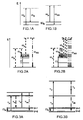
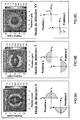
- a pulsating pump wave ⁇ P incident on a molecule is inelastically diffused into a so-called Stokes pulsation wave ⁇ S ( Figure 1A ) and a so-called anti-Stokes wave of pulsation ⁇ AS ( Figure 1B ).
- Photonics of the process, the Stokes and anti-Stokes waves correspond to an absorption from respectively the fundamental or excited vibrational level.
- the process generating the anti-Stokes wave, starting from the excited vibrational level, is much less likely than the process creating the Stokes wave, which is the only one observed in practice in spontaneous Raman spectroscopy.
- a fine study of the spectral distribution of Stokes waves gives information on the densities of chemical bonds present in the sample. This spontaneous process of inelastic scattering is very inefficient compared to fluorescence (the Raman cross sections are of the order of 10 -30 cm / molecule, compared with the 1-photon absorption cross section of a fluorophore that reaches 10 16 cm 2 / molecule).
- CARS Coherent Anti-Stokes Raman Scattering
- Raman Spectroscopy is a four-wave mixing process that addresses the vibrational bonds present in a sample. This process is for example described in RW Boyd, Nonlinear Optics (Boston Academic Press, 1992) ). It is a question of sending two laser pulses of pulsations ⁇ p and ⁇ s (or of frequencies ⁇ p and ⁇ s whose difference of pulsations is made equal to the pulsation ⁇ of the vibrational level which one wants to address.
- CARS broadcast signal This new radiation ⁇ as (hereinafter referred to as the "CARS broadcast signal") is the signature of the presence of the vibrating link at the ⁇ pulse in the sample.
- CARS broadcast signal A first implementation of CARS is to send on the sample two spectrally fine picosecond pulses whose pulse difference will only address a specific vibrational connection. For optimal identification, all the vibrational links present in the sample are searched for.
- Multiplex CARS (see for example M. Muller and J. Schins, "Imaging the thermodynamic state of lipidic membranes with multiplex CARS spectroscopy,” Physical Chemistry B 106, 3715-3723 (2002). )) where is sent on the sample a pulse ⁇ p fine spectrally and a pulse ⁇ s broad spectrally ( Figure 2B ). It is thus possible to address all the vibrational levels ⁇ i present in the sample and obtain a spectrum of the signal ⁇ as generated. From the technical point of view, the narrow spectrum is for example derived from a picosecond laser and the broad spectrum, for example of a femtosecond laser, or a photonic crystal fiber generating a supercontinuum (SC).
- SC supercontinuum
- the heterodyne detection scheme reported in the application WO 2005/124322 cited above is applied and the laser source used is composed of a picosecond laser emitting at 1064 nm and doubled at 532 nm.
- the 532 nm beam then pumps an optical parametric oscillator (OPO).
- OPO optical parametric oscillator
- the OPO generates two wavelengths "signal" ⁇ signal and "idler" ⁇ idler tunable according to 1 / ⁇ signal (nm) + ⁇ idler (nm) 1/532 (nm).
- the beams at 1064 nm and idler then play respectively the roles of pump and Stokes beam.
- the signal beam is at the same wavelength as the anti-Stokes beam generated in the sample. It is recombined with the anti-Stokes beam and the signal resulting from this interference is detected according to the heterodyne interferometry method described in the application WO 2005/124322 .
- This highly efficient technique requires the use of an OPO that can generate both signal and idler wavelengths.
- the non-resonant noise of the CARS signal is then removed by demodulating the CARS signal at the frequency v.
- this method requires a source emitting two wavelengths and a good contrast between the resonant and non-resonant signals between which the modulation operates.
- the resonant and non-resonant CARS signals are then generated in different polarizations.
- a polarizer is then introduced after the sample to extinguish the non-resonant signal and pass the non-extinct resonant signal fraction. This method is simple to implement but drastically decreases the detected resonant signal level. This reduction is all the stronger as the "depolarization coefficient" of the Raman resonance probed is close to 1/3.
- CARS Coherent anti-Stokes Raman scattering
- the present invention proposes an original method of detecting a resonant non-linear optical signal that is simple to implement and that is compatible with fast imaging, and that makes it possible to overcome non-resonant CARS noise in microscopic imaging applications. spectroscopy. This method is based on the analysis of the direction of diffusion of the CARS signal at the axial interface of a resonant and non-resonant medium, and more precisely on the analysis of the angular deviation of the signal.
- the invention relates to a device for detecting a resonant non-linear optical signal induced in a sample of the type comprising a resonant medium and a non-resonant medium forming an interface.
- the device according to the first aspect comprises a source of emission of at least a first excitation light beam, said pump beam, at a first given pulsation ⁇ p , adapted to the excitation of the resonant medium of a sample of the given type, an optical detection module adapted to the detection of a non-linear optical signal resulting from the interaction of said pump beam with an axial interface between the resonant and non-resonant media of the sample, in at least two directions symmetrical with respect to the optical axis of said beam pump incident in the sample, and a processing unit adapted to the processing of the signals thus detected to obtain the difference of said signals, the resulting difference signal being characteristic of a vibrational or electronic resonance of the resonant medium of the sample.
- the device thus described makes it possible to analyze the angular deviation of the nonlinear optical signal resulting from the interaction of said beam (s) with the sample, making it possible to obtain at an axial interface of the resonant and non-resonant media a characteristic signal of a vibrational or electronic resonance of the resonant medium.
- the emission source makes it possible to transmit a pulsating pump beam ⁇ p and a pulsating Stokes beam ⁇ s, the nonlinear optical signal resulting from the interaction of said pump and Stokes beams being a so-called signal.
- distributed signal CARS, of pulsation ⁇ as 2 ⁇ p - ⁇ s and the signal resulting from the analysis of the transmission direction of the broadcast signal CARS, a characteristic signal of a Raman emission of the resonant medium.
- the optical detection module comprises at least one occultation mask and at least one detector, making it possible to detect the nonlinear optical signal integrated in two complementary half-spaces, symmetrical with respect to the optical axis, the difference being performed on the integrated signals in both half-spaces.
- the optical detection module comprises an image recording system enabling point-to-point detection of the nonlinear optical signal collected in directions that are symmetrical with respect to the optical axis, the difference being made for each pair. signals thus detected
- the optical detection module of said nonlinear optical signal comprises a mask rotating around the optical axis at a given frequency (v), the mask partially obscuring said signal, and a detector making it possible to detect the optical signal integrated in the part of the space not obscured by the mask to deliver a modulated signal to said frequency of rotation of the mask and having a maximum value and a minimum value, and the processing unit allows the processing of the modulated signal to obtain the amplitude of the frequency component of the signal at said frequency of rotation of the mask, the amplitude being proportional to the difference between said maximum and minimum values and being characteristic of a vibrational or electronic resonance of the resonant medium.
- the device further comprises an angular scanning device of the excitation beam or beams, enabling the excitation beam or beams to intercept the sample at different positions of the interface between the resonant and non-resonant medium. resonant.
- the emission source emits at least one variable wavelength excitation beam, making it possible to obtain a spectrum of the vibrational or electronic resonances of the resonant medium.
- the invention relates to a method for the detection of a non-linear resonant optical signal induced in a sample, the sample comprising a resonant medium and a non-resonant medium forming an interface, the method comprising: at least one first excitation light beam of the resonant medium, said pump beam, at a first given pulsation ⁇ p , said pump beam being incident on the sample along an optical axis, and intercepting said interface between the resonant medium and the non-resonant medium, the detection of the non-linear optical signal resulting from the interaction of said excitation beam (s) with an axial interface between the resonant and non-resonant media of the sample, in at least two directions symmetrical with respect to the optical axis, and the processing of the signals thus detected making it possible to obtain the difference of said signals, the resulting difference signal etan t characteristic of a vibrational or electronic resonance of the resonant medium of the sample.
- the detection of the nonlinear optical signal is done by integrating the signal into two complementary half-spaces, symmetrical with respect to the optical axis, and the processing includes calculating the difference between the integrated signals in the two half-spaces.
- the detection of the nonlinear optical signal is made by point-to-point detection of the non-linear optical signal in directions symmetrical with respect to the optical axis, and the processing comprises the calculation of the difference between the signals of each couple of signals thus detected.
- the detection of the nonlinear optical signal comprises the partial concealment of said non-linear optical signal by means of a mask rotating around the optical axis at a given frequency (v) and the detection of the integrated optical signal.
- the processing comprises determining the amplitude of the frequency component at said frequency of rotation of the mask of said modulated signal, the amplitude being proportional to the difference between said maximum and minimum values of the modulated signal and being characteristic of a vibrational or electronic resonance of the resonant medium.
- the excitation beam or beams are angularly scanned to intercept the sample at different positions of the interface between the resonant and non-resonant medium.
- At least one of the excitation beams has a variable emission wavelength, making it possible to obtain a spectrum of the vibrational or electronic resonances of the resonant medium.
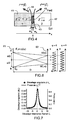
- the figure 4 represents a sample comprising a resonant medium 41, for example a medium containing the medium to be analyzed, that is to say the medium of biological interest, and a non-resonant medium 42, typically a medium containing the solvent.
- the non-linear susceptibility of the 3 rd (3) order is defined in the resonant medium 41 by a resonant term ⁇ (3) 1R and a non-resonant term ⁇ (3) 1NR .
- the non-resonant medium 42 it is defined by the non-resonant term ⁇ (3) 2NR .
- the invention consists in spatially analyzing the signal broadcast by CARS process, referenced 44 on the figure 4 , resulting from the interaction of a pulsating pump beam ⁇ p and a pulsating probe beam ⁇ s , collinear, incident on the sample in a focusing volume 45, with an axial interface of the sample, c that is to say having a non-zero component along the axis of the incident pump and Stokes beams.
- the method consists of analyzing the light intensity of the nonlinear optical beam in the space of the wave vectors k , that is to say in the space of the directions of emission of the signal emitted by CARS processes, on both sides of the interface, this intensity being noted on the figure 4 respectively I Fwd ( k ) and I Fwd ( k ') on both sides of the interface.
- the abbreviation "Fwd” represents the CARS signal diffused towards the front, as opposed to the so-called "Epi” signal, diffused towards the rear.
- FIGS. 5A to 5E represent by a series of diagrams the deviation of the broadcast signal CARS as a function of the relative position of the pump and Stokes beams incident with the interface.
- FIGS. 5A to 5E show the active volume CARS 45 (focussing spot of the pump and Stokes beams) which is displaced through a CARS object 50 (each sticker corresponds to a position different from the active volume in the object).
- the object CARS is considered as resonant while the medium surrounding the object is considered as non-resonant (it will be called in the following description "the solvent”). It appears that at the axial interfaces between the CARS object and the solvent, the broadcast signal CARS is affected by a deviation (or tilt).
- the applicant has shown that this experimental finding could be explained by a simple model based on the Young Slots theory.
- the figure 6 represents the montage Experimental Young's Slits.
- a monochromatic S light source (not shown on the figure 6 ) illuminates a plate 61 pierced with two slots (denoted A and B). These behave as secondary light sources of amplitude E1 and E2.
- E1 and E2 the luminous intensity measured at a point M (x) from screen 62.
- I x E 1 2 + E 2 2 + 2 E 1 ⁇ E 2 ⁇ cos 2 ⁇ ⁇ x ⁇ D
- I (x) E 1 2 + E 2 2 + 2 E 1 ⁇ E 2 ⁇ cos 2 ⁇ ⁇ x ⁇ D + ⁇
- phase shift ⁇ originates from the signature of a molecular vibration of the resonant medium. It follows from this expression that the difference ⁇ I ( k ) is proportional to the imaginary part of the nonlinear susceptibility of order 3 of the resonant medium, that is to say of the pure Raman spectrum of the medium 1.
- the figure 7 presents the results of a rigorous numerical computation taking into account the vectorial nature of the pump and Stokes beams focused on an axial interface between a resonant medium 1 and a non-resonant medium 2 ( figure 4 ).
- Dk-CARS Differential imaging in K-space
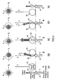
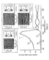
- the Figures 9A to 9C present 3 possible detection modes for Dk-CARS microscopy.
- a numerical simulation represents the image obtained for a 3 ⁇ m diameter ball in an aqueous-type solvent (pump wavelength 730 nm, Stokes wavelength 787 nm, numerical aperture of the objective lens). 1.2 excitation in the water, numerical aperture of the collection lens 0.5 in the air).
- the image is calculated in each case in an XY plane corresponding to the equatorial plane of the ball, perpendicular to the direction of incidence Z (see figure 5 ) excitation beams.
- the Figure 9A represents the X detection mode allowing detection at interfaces perpendicular to the X axis.
- the difference of the integrated luminous intensities in space (k x > 0) is calculated (problem ⁇ , Figure 9A ) and in space (k x ⁇ 0) (problem ⁇ , Figure 9A ).
- the Figure 9B represents the detection mode Y allowing a detection at the interfaces perpendicular to the axis Y.
- one calculates for different positions the difference of the luminous intensities integrated in the space (k y > 0) (problem ⁇ , Figure 9B ) and in space (k y ⁇ 0) (problem ⁇ , Figure 9B ).
- the Figure 9C represents the XY detection mode.
- the image is calculated by the difference in pairs of the light intensities I ⁇ (k x, k y) and I ⁇ (k x - k y) measured in two directions k (k x , k y , k z ) and k "(-k x , -k y , k z ) opposite, respectively corresponding to the problems ⁇ and ⁇ on the Figure 9C , the directions being contained in the angular cone whose opening angle is defined by the numerical opening of collection of the diffused signal CARS (for example 0.5 in the air). In this last mode of detection, all the interfaces are visible in an equatorial plane of the ball.
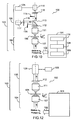
- the figure 10 represents a first example of experimental implementation of Dk-CARS, suitable for example for the detection modes of FIGS. 9A or 9B , for the study of a sample comprising an interface between a resonant medium and a non-resonant medium.
- the detection device 100 generally comprises a laser system 101 for transmitting a first pulsation excitation beam ⁇ p (pump beam) and a second pulsation excitation beam ⁇ s (Stokes beam), the two excitation beams. symbolized by the arrow 102 being collinear and incident in a main direction Z in an optical detection module of the device generally referenced 103.
- the optical detection module 103 generally comprises means 104 for causing the excitation beams to interact with the sample 105 , positioned in an XY plane substantially perpendicular to the main direction Z, and means for analyzing the direction of diffusion of the CARS signal resulting from the interaction of the excitation beams with the sample 105, and more precisely of the deviation angular of the CARS signal, comprising an optical detection module 106 and a processing unit 125.
- the laser system 101 comprises, for example, in a so-called two-color application , two spectrally thin tunable laser sources 108, for example of the Titanium-Sapphire type, emitting between 690 and 1000 nm, pumped by a pump laser 109, Nd type: YVO4 emitting at 532 nm.
- the tunable lasers emit, for example, picosecond pulses (ps), typically of the order of 3 ⁇ s, to form the pulsation pump excitation beams ⁇ p (of typical wavelength 730 nm) and pulsating Stokes ⁇ s . .
- a pulse picker 110 may be used to reduce the rate of the pump and probe excitation lasers without reducing the peak power of the pulses.
- the use of a Stokes beam or a Tunable pump beam notably makes it possible to scan the anti-Stokes emission spectrum for spectroscopic applications intended to determine the Raman spectrum of the resonant medium.
- Other tunable laser sources may be used, for example of the optical parametric oscillator (OPO) type, optical parametric amplifier (OPA), Nd-type picosecond oscillators: glass, Ytterbium or Erbium doped fiber lasers, etc.
- the sources can also be nanosecond (ns) or femtosecond (fs) laser sources, depending on the spectral width of the Raman lines that one wants to observe.
- the nanosecond pulses if very good from a spectral point of view, have a lower peak power than the ps pulses and a lower repetition frequency.
- thermal effects associated with ns pulses are more likely to damage biological samples.
- Gross femtosecond pulses are generally too broad spectrally.
- the linewidths are around 10-20 cm -1 , which corresponds to the use of picosecond pulses.
- the means 104 comprise, for example, a focus objective 107 of the excitation beams for focusing the pump and Stokes beams into a common focusing volume for analyzing the sample.
- a focus lens is particularly suitable in microscopy type applications. However, it is not essential for the transmission of the CARS signal to work in focussed beams, and in particular in the case of the study of thin samples.
- the optical detection module 106 comprises a collection objective 111 making it possible to collect the nonlinear optical signal emitted, in this example the CARS signal, a filter 112 for cutting off the excitation signals, an optical element for separating the beams according to two lanes, and on each lane, a blade 114, 115, razor blade type, for defining two complementary half-spaces.
- the blades are arranged to delimit the two half-spaces (k x > 0) and (k x ⁇ 0) corresponding to the detection mode X ( Figure 9A ).
- the blades could be arranged to delimit two half-spaces (k y > 0) and (k y ⁇ 0) corresponding to the detection mode Y ( Figure 9B ).
- a detector 116, 117 disposed behind the blade can measure the light intensity in each half-space.
- the detector is for example of the avalanche photodiode (APD), fast photodiode (PIN), or photomultiplier (PMT) type.
- the detector may be preceded by collection optics 118, 119.
- a processing unit receives the signals detected by the detectors 116, 117 and determines the difference ⁇ I of the light intensities measured on each of the channels, which the applicant has shown to be proportional to the Raman spectrum of the resonant medium.
- the means 104 also comprise a device for scanning the excitation beams in the XY plane of the sample.
- This scanning device may be useful both in an application in spectroscopy, to adjust the focus location of the excitation beams on an axial interface of the resonant and non-resonant media forming the sample, or in an imaging application. It may be a device allowing the displacement of the sample, or, preferably, an angular scanning device of the excitation beams (not shown on FIG. figure 10 ).
- the excitation beams are incident along an axis (optical axis) which is not necessarily confused with the main direction Z.
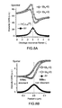
- the figure 11 represents experimental results obtained with the experimental setup of the figure 10 .
- the wavelength of the pump beam is set at 730 nm and the wavelength of the Stokes beam is varied so as to traverse the aforementioned Raman resonance.
- the curve C1 represents the intensity CARS, that is to say the intensity of light integrated throughout the space.
- the curve C2 (solid line) represents the difference of the intensities ⁇ I measured respectively in the half spaces (k x > 0) and (k x ⁇ 0).
- the figure 10 thus shows a particularly simple embodiment for implementing the Dk-CARS detection. Many variations are possible.
- the razor blades 115, 116 may be replaced by any type of concealment mask that makes it possible to delimit two complementary half-spaces.
- these masks can be arranged directly on the optical separation element 113.
- the optical detection module 106 comprises only one channel, with a single detector, of the avalanche photodiode or photomultiplier type, using for example an adaptive filter, for example an electrically controlled liquid crystal filter.
- an adaptive filter for example an electrically controlled liquid crystal filter.
- the figure 12 represents a variant of the figure 10 , in which the means for analyzing the direction of diffusion of the CARS signal comprise an optical detection module 106 with a single channel, adapted to detection in XY mode ( Figure 9C ).
- the occultation mask system is replaced by a single detector formed of an image recording system, for example a CCD or CMOS type matrix camera, or a 4-quadrant photodiode.
- the use of the camera makes it possible to detect point-to-point the nonlinear optical signal emitted in directions symmetrical with respect to the direction of incidence of the excitation beams on the camera (when the filter 112 has been removed), the difference being performed for each pair of signals thus detected.
- the direction of incidence of the excitation beams varies and calibration can be carried out, for example by identifying the position of the excitation beams on the detector, for the different scanning positions. It is also possible to calibrate the camera "in solution". For this purpose, it will be possible for example to identify the position of the signal, for different angles of incidence of the excitation beams, when the excitation beams are focused in a homogeneous CARS medium and that there is therefore no deviation of the broadcast signal CARS. The offset will then be measured with respect to this reference position.
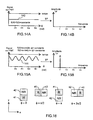
- FIG. 13A illustrates another variant of the means for analyzing the direction of transmission of the CARS signal.
- a sample 105 ( Figure 13B ) comprising a resonant medium and a non-resonant medium forming an interface, is excited by a pump beam and a Stokes beam, collinear, incident on the sample in a common focusing volume 45.
- the optical detection module 106 comprises a rotating mask 130 around the main direction Z at a given frequency (v).
- This mask for example formed of a half-disk 134 as shown on the figure 13C partially obscures the broadcast signal CARS in an XY plane perpendicular to the main direction Z.
- the signal thus occulted is detected by a detector 132, for example of photomultiplier type, PIN photodiode or avalanche photodiode, preceded by focusing optics 131.
- the broadcast signal CARS is centered and the signal detected by the detector 132 is constant as a function of the angular position ⁇ of the mask ( ⁇ being for example defined with respect to the x axis, as illustrated on FIG. figure 13C ).
- the detected signal S ( ⁇ ) is constant.
- the harmonics of the signal at the frequency ⁇ are zero ( Figure 14B ).
- the processing unit 125 makes it possible to demodulate the signal at the frequency v, by calculating the Fourier transform, or, advantageously, by means of a synchronous detection, in order to determine the (non-zero) amplitude of the Fourier transform at the frequency v.
- This amplitude is proportional to the difference between the maximum and minimum values of the signal S (t). It is proportional to the imaginary part Im [ ⁇ (3) 1R ] of the medium 1; it is therefore characteristic of a vibrational resonance of the resonant medium and thus makes it possible to determine the Raman spectrum in a spectroscopy application, or in microscopy, to obtain contrasting images at the axial interfaces.
- the determination of the phase ⁇ of the modulated signal at the first harmonic v makes it possible to provide information on the orientation and the relative position of the resonant and non-resonant media.
- the rotating mask forms other than a half-disk, such as for example a quarter disc or three quarter disc.
- the rotating mask can be made mechanically, as has been described, or by means of an electrically controllable filter, for example a liquid crystal filter.
- the figure 13A shows the application of the method to microscopy, when using a scanning system pump and Stokes excitation beams.
- the analysis of the direction of diffusion of the signal CARS is made in far field.
- the use of the collection objective 111 ( figure 10, 12 , 13A ) facilitates the experimental implementation.
- this collection objective is not strictly necessary and the detection could be done directly after the sample
- Dk-CARS detection has been described in a two-color application using two spectrally thin laser sources.
- multiplexed application it will be possible to choose a source of emission of the spectrally broad Stokes beam, generated for example by a femtosecond pulse or by a supercontinuum generated by an optical fiber or another dispersive medium.
- the pump signal remains thin spectrally.
- it will be possible to acquire a Raman spectrum in a single pulse for example using two slit spectrometers or a single spectrometer equipped with a CCD camera in which the two detected signals are injected into the two half-spaces.
- three associated pulse wavelengths ⁇ 1 , ⁇ 2 and ⁇ 3 are used to generate a CARS signal at the pulsation ⁇ 1 - ⁇ 2 + ⁇ 3 .
- the CARS signal can be rendered without non-resonant noise by detecting the signals at the pulsation ⁇ 1 - ⁇ 2 + ⁇ 3 in the half spaces (k x > 0) and (k x ⁇ 0) and making their difference.
- the detection method has been described in the case of the CARS diffusion, it is equally applicable to other non-linear process, the 2 nd or 3 rd order for both spectroscopy applications or for detection microscopy applications at axial interfaces, thus revealing interfaces between resonant and non-resonant media.
- an analysis is made of the direction of emission of the nonlinear optical signal resulting from the interaction of one or more excitation beams with a sample having an interface between a resonant medium and a non-resonant medium. This analysis of the direction of emission makes it possible either to reveal the interface between the resonant medium and the non-resonant medium, or to characterize a spectrum of the resonant medium.
- a resonant third harmonic generation process in which the resonance is an electronic resonance, by exciting with a single pump excitation beam, of a pulsation ⁇ p , a sample comprising an interface between a resonant medium and a non-resonant medium.
- a picosecond or femtosecond laser source of Ti: Saphir, Nd: glass, Ytterbium or Erbium doped fiber laser type is used.
- a resonant four-wave mixing process in which the resonance is an electronic resonance, by exciting with a single pump excitation beam, of a pulsation ⁇ p , a sample comprising an interface between a resonant medium and a non-resonant medium.
- a picosecond or femtosecond laser source of Ti: Saphir, Nd: glass, Ytterbium or Erbium doped fiber laser type is used.
- the second harmonic can be excite resonant beam with a single pump, or it may make the sum frequency with a pump beam and a probe beam (non-linear effect of the 2 nd order).
- the detection device and the method according to the invention comprises various variants, modifications and improvements which will be obvious to those skilled in the art, it being understood that these various variants, modifications and improvements are within the scope of the invention, as defined by the following claims.
Landscapes
- Health & Medical Sciences (AREA)
- Nuclear Medicine, Radiotherapy & Molecular Imaging (AREA)
- Physics & Mathematics (AREA)
- Life Sciences & Earth Sciences (AREA)
- Chemical & Material Sciences (AREA)
- Analytical Chemistry (AREA)
- Biochemistry (AREA)
- General Health & Medical Sciences (AREA)
- General Physics & Mathematics (AREA)
- Immunology (AREA)
- Pathology (AREA)
- Investigating, Analyzing Materials By Fluorescence Or Luminescence (AREA)
Applications Claiming Priority (2)
| Application Number | Priority Date | Filing Date | Title |
|---|---|---|---|
| FR1000244A FR2955663B1 (fr) | 2010-01-22 | 2010-01-22 | Methode pour la detection d'un signal optique non lineaire resonant et dispositif pour la mise en oeuvre de ladite methode |
| PCT/EP2011/050622 WO2011089119A1 (fr) | 2010-01-22 | 2011-01-18 | Methode pour la detection d'un signal optique non lineaire resonant et dispositif pour la mise en oeuvre de ladite methode |
Publications (2)
| Publication Number | Publication Date |
|---|---|
| EP2526408A1 EP2526408A1 (fr) | 2012-11-28 |
| EP2526408B1 true EP2526408B1 (fr) | 2014-03-19 |
Family
ID=42562452
Family Applications (1)
| Application Number | Title | Priority Date | Filing Date |
|---|---|---|---|
| EP11703623.6A Not-in-force EP2526408B1 (fr) | 2010-01-22 | 2011-01-18 | Methode pour la detection d'un signal optique non lineaire resonant et dispositif pour la mise en oeuvre de ladite methode |
Country Status (5)
| Country | Link |
|---|---|
| US (1) | US8804117B2 (ja) |
| EP (1) | EP2526408B1 (ja) |
| JP (1) | JP5558587B2 (ja) |
| FR (1) | FR2955663B1 (ja) |
| WO (1) | WO2011089119A1 (ja) |
Families Citing this family (12)
| Publication number | Priority date | Publication date | Assignee | Title |
|---|---|---|---|---|
| WO2013066447A1 (en) | 2011-08-01 | 2013-05-10 | The Trustees Of Columbia University In The City Of New York | Lens-free planar imager and wireless transmitter |
| WO2013059665A1 (en) | 2011-10-19 | 2013-04-25 | The Trustees Of Columbia University In The City Of New York | Ultracompact fabry-perot array for ultracompact hyperspectral imaging |
| WO2013148349A1 (en) | 2012-03-30 | 2013-10-03 | The Trustees Of Columbia University In The City Of New York | Graphene photonics for resonator-enhanced electro-optic devices and all-optical interactions |
| WO2013176759A1 (en) * | 2012-03-30 | 2013-11-28 | The Trustees Of Columbia University In The City Of New York | Systems and methods for chip-integrated infrared silicon detector |
| US9212948B2 (en) | 2012-11-07 | 2015-12-15 | The Trustees Of Columbia University In The City Of New York | Lossless hyperspectral imaging |
| US9927397B1 (en) * | 2013-11-26 | 2018-03-27 | Stc.Unm | Innovative nanopore sequencing technology including a self-assembled porous membrane |
| CN104185353B (zh) * | 2014-09-05 | 2016-08-24 | 中国人民解放军陆军军官学院 | 一种基于汤姆逊散射弱相干技术的聚变堆等离子体密度温度诊断方法 |
| DE112015006288B4 (de) * | 2015-03-11 | 2023-12-28 | Hitachi High-Tech Corporation | Optische Messvorrichtung und optisches Messverfahren |
| JP6765648B2 (ja) * | 2016-07-13 | 2020-10-07 | 国立大学法人東京農工大学 | 光検出装置、光検出方法および光検出プログラム |
| WO2022165276A1 (en) | 2021-01-29 | 2022-08-04 | Armonica Technologies, Inc. | Enhancement structures for surface-enhanced raman scattering |
| CN113252085B (zh) * | 2021-06-30 | 2021-09-17 | 中国人民解放军国防科技大学 | 含非线性机械振子的光机械微腔结构、测量系统及方法 |
| CN113948944B (zh) * | 2021-10-15 | 2024-04-09 | 复旦大学 | 一种基于共振四波混频产生相干太赫兹脉冲的方法 |
Family Cites Families (12)
| Publication number | Priority date | Publication date | Assignee | Title |
|---|---|---|---|---|
| US5042952A (en) * | 1984-05-21 | 1991-08-27 | Therma-Wave, Inc. | Method and apparatus for evaluating surface and subsurface and subsurface features in a semiconductor |
| US5303710A (en) * | 1992-11-03 | 1994-04-19 | The United States Of America As Represented By The Secretary Of The Navy | Apparatus for imaging an object in or through a scattering medium using coherent anti-Stokes Raman scattering |
| DE4243144B4 (de) * | 1992-12-19 | 2008-08-21 | BRUKER OPTICS, Inc., Billerica | Objektiv für ein FT-Raman-Mikroskop |
| ATE543080T1 (de) | 2000-07-13 | 2012-02-15 | Harvard College | System und verfahren für die epidetektions- kohärenz-anti-stokes-raman-streumikroskopie |
| JP4854878B2 (ja) * | 2001-07-03 | 2012-01-18 | オリンパス株式会社 | レーザー顕微鏡 |
| US6789507B1 (en) | 2002-09-03 | 2004-09-14 | Paul Davis Slate | Oxygen flow control process for hatchery hatchers |
| US7388668B2 (en) * | 2004-06-09 | 2008-06-17 | President & Fellows Of Harvard College | Phase sensitive heterodyne coherent anti-Stokes Raman scattering micro-spectroscopy and microscopy |
| JP4954452B2 (ja) * | 2004-07-06 | 2012-06-13 | オリンパス株式会社 | 顕微鏡 |
| US7586618B2 (en) * | 2005-02-28 | 2009-09-08 | The Board Of Trustees Of The University Of Illinois | Distinguishing non-resonant four-wave-mixing noise in coherent stokes and anti-stokes Raman scattering |
| US7352458B2 (en) | 2005-10-26 | 2008-04-01 | President And Fellows Of Harvard College | System and method for high sensitivity vibrational imaging with frequency modulation coherent anti-stokes Raman scattering analyses |
| DE102007021378A1 (de) | 2007-05-04 | 2008-11-06 | Ape Angewandte Physik Und Elektronik Gmbh | Verfahren und optische Anordnung zum Erzeugen eines nicht-linearen optischen Signals an einem durch ein Anregungsfeld angeregten Material sowie Verwendung des Verfahrens und der optischen Anordnung |
| KR100929202B1 (ko) * | 2008-02-27 | 2009-12-01 | 광주과학기술원 | 가간섭성 반스토크스 라만 산란을 이용한 영상 획득 장치및 방법 |
-
2010
- 2010-01-22 FR FR1000244A patent/FR2955663B1/fr not_active Expired - Fee Related
-
2011
- 2011-01-18 WO PCT/EP2011/050622 patent/WO2011089119A1/fr active Application Filing
- 2011-01-18 EP EP11703623.6A patent/EP2526408B1/fr not_active Not-in-force
- 2011-01-18 JP JP2012549334A patent/JP5558587B2/ja not_active Expired - Fee Related
- 2011-01-18 US US13/574,482 patent/US8804117B2/en not_active Expired - Fee Related
Also Published As
| Publication number | Publication date |
|---|---|
| FR2955663B1 (fr) | 2014-09-12 |
| WO2011089119A1 (fr) | 2011-07-28 |
| JP5558587B2 (ja) | 2014-07-23 |
| US8804117B2 (en) | 2014-08-12 |
| JP2013517491A (ja) | 2013-05-16 |
| US20130021606A1 (en) | 2013-01-24 |
| EP2526408A1 (fr) | 2012-11-28 |
| FR2955663A1 (fr) | 2011-07-29 |
Similar Documents
| Publication | Publication Date | Title |
|---|---|---|
| EP2526408B1 (fr) | Methode pour la detection d'un signal optique non lineaire resonant et dispositif pour la mise en oeuvre de ladite methode | |
| EP2979080B1 (fr) | Dispositif et methode de detection raman stimulee | |
| EP2522969A2 (en) | Nonlinear raman spectroscopic apparatus comprising single mode fiber for generating Stokes beam | |
| JP5736325B2 (ja) | 光学装置 | |
| US8064053B2 (en) | 3-color multiplex CARS spectrometer | |
| WO2014125729A1 (ja) | 測定装置及び測定方法 | |
| US9869591B2 (en) | Cars microscope | |
| EP3234666A1 (fr) | Dispositif de transport et de contrôle d'impulsions lumineuses pour l'imagerie endo-microscopique sans lentille | |
| EP2715885A1 (fr) | Procédé et dispositif de génération d'impulsions attosecondes isolées | |
| US20180045571A1 (en) | Optical measurement device and optical measurement method | |
| Ito et al. | Single-beam phase-modulated stimulated Raman scattering microscopy with spectrally focused detection | |
| Coluccelli et al. | Broadband Fourier-transform coherent Raman spectroscopy with an ytterbium fiber laser | |
| EP2526407B1 (fr) | Méthode pour la détection d'un signal optique non linéaire résonant et dispositif pour la mise en oeuvre de ladite méthode | |
| EP0426571A1 (fr) | Procédé d'analyse spectroscopique ponctuelle de la lumière diffractée ou absorbée par une substance placée dans un champ proche | |
| JP3816306B2 (ja) | 超高速時間分解蛍光分光方法 | |
| WO2017148858A1 (fr) | Dispositif optique d'excitation pour générer des processus raman stimulés, ensemble de mesure de processus raman stimulés et procédé d'excitation optique pour générer des processus raman stimulés | |
| EP3919893A1 (fr) | Procédés et dispositifs de détection d'un signal de diffusion raman stimulée (srs) dans un échantillon | |
| WO2023112909A1 (ja) | タイムストレッチ光測定器およびタイムストレッチ分光法 | |
| EP1419415B1 (fr) | Source laser ultrabreve compacte a spectre large controle | |
| EP3423882B1 (fr) | Miscroscopie optique non-linéaire quantitative | |
| WO2019142907A1 (ja) | 光学分析装置および光学分析方法 | |
| CN116380856A (zh) | 瞬态受激拉曼激发荧光光谱方法与系统 | |
| Ozeki et al. | High‐Speed 3D Spectral Imaging with Stimulated Raman Scattering |
Legal Events
| Date | Code | Title | Description |
|---|---|---|---|
| PUAI | Public reference made under article 153(3) epc to a published international application that has entered the european phase |
Free format text: ORIGINAL CODE: 0009012 |
|
| 17P | Request for examination filed |
Effective date: 20120817 |
|
| AK | Designated contracting states |
Kind code of ref document: A1 Designated state(s): AL AT BE BG CH CY CZ DE DK EE ES FI FR GB GR HR HU IE IS IT LI LT LU LV MC MK MT NL NO PL PT RO RS SE SI SK SM TR |
|
| DAX | Request for extension of the european patent (deleted) | ||
| GRAP | Despatch of communication of intention to grant a patent |
Free format text: ORIGINAL CODE: EPIDOSNIGR1 |
|
| INTG | Intention to grant announced |
Effective date: 20131007 |
|
| GRAS | Grant fee paid |
Free format text: ORIGINAL CODE: EPIDOSNIGR3 |
|
| GRAA | (expected) grant |
Free format text: ORIGINAL CODE: 0009210 |
|
| AK | Designated contracting states |
Kind code of ref document: B1 Designated state(s): AL AT BE BG CH CY CZ DE DK EE ES FI FR GB GR HR HU IE IS IT LI LT LU LV MC MK MT NL NO PL PT RO RS SE SI SK SM TR |
|
| REG | Reference to a national code |
Ref country code: GB Ref legal event code: FG4D Free format text: NOT ENGLISH |
|
| REG | Reference to a national code |
Ref country code: CH Ref legal event code: EP |
|
| REG | Reference to a national code |
Ref country code: AT Ref legal event code: REF Ref document number: 657983 Country of ref document: AT Kind code of ref document: T Effective date: 20140415 |
|
| REG | Reference to a national code |
Ref country code: IE Ref legal event code: FG4D Free format text: LANGUAGE OF EP DOCUMENT: FRENCH |
|
| REG | Reference to a national code |
Ref country code: DE Ref legal event code: R096 Ref document number: 602011005527 Country of ref document: DE Effective date: 20140430 |
|
| REG | Reference to a national code |
Ref country code: DE Ref legal event code: R082 Ref document number: 602011005527 Country of ref document: DE Representative=s name: JOSTARNDT PATENTANWALTS-AG, DE |
|
| PG25 | Lapsed in a contracting state [announced via postgrant information from national office to epo] |
Ref country code: NO Free format text: LAPSE BECAUSE OF FAILURE TO SUBMIT A TRANSLATION OF THE DESCRIPTION OR TO PAY THE FEE WITHIN THE PRESCRIBED TIME-LIMIT Effective date: 20140619 Ref country code: LT Free format text: LAPSE BECAUSE OF FAILURE TO SUBMIT A TRANSLATION OF THE DESCRIPTION OR TO PAY THE FEE WITHIN THE PRESCRIBED TIME-LIMIT Effective date: 20140319 |
|
| REG | Reference to a national code |
Ref country code: NL Ref legal event code: VDEP Effective date: 20140319 |
|
| REG | Reference to a national code |
Ref country code: AT Ref legal event code: MK05 Ref document number: 657983 Country of ref document: AT Kind code of ref document: T Effective date: 20140319 |
|
| REG | Reference to a national code |
Ref country code: LT Ref legal event code: MG4D |
|
| PG25 | Lapsed in a contracting state [announced via postgrant information from national office to epo] |
Ref country code: CY Free format text: LAPSE BECAUSE OF FAILURE TO SUBMIT A TRANSLATION OF THE DESCRIPTION OR TO PAY THE FEE WITHIN THE PRESCRIBED TIME-LIMIT Effective date: 20140319 Ref country code: FI Free format text: LAPSE BECAUSE OF FAILURE TO SUBMIT A TRANSLATION OF THE DESCRIPTION OR TO PAY THE FEE WITHIN THE PRESCRIBED TIME-LIMIT Effective date: 20140319 Ref country code: SE Free format text: LAPSE BECAUSE OF FAILURE TO SUBMIT A TRANSLATION OF THE DESCRIPTION OR TO PAY THE FEE WITHIN THE PRESCRIBED TIME-LIMIT Effective date: 20140319 |
|
| PG25 | Lapsed in a contracting state [announced via postgrant information from national office to epo] |
Ref country code: RS Free format text: LAPSE BECAUSE OF FAILURE TO SUBMIT A TRANSLATION OF THE DESCRIPTION OR TO PAY THE FEE WITHIN THE PRESCRIBED TIME-LIMIT Effective date: 20140319 Ref country code: HR Free format text: LAPSE BECAUSE OF FAILURE TO SUBMIT A TRANSLATION OF THE DESCRIPTION OR TO PAY THE FEE WITHIN THE PRESCRIBED TIME-LIMIT Effective date: 20140319 Ref country code: LV Free format text: LAPSE BECAUSE OF FAILURE TO SUBMIT A TRANSLATION OF THE DESCRIPTION OR TO PAY THE FEE WITHIN THE PRESCRIBED TIME-LIMIT Effective date: 20140319 |
|
| PG25 | Lapsed in a contracting state [announced via postgrant information from national office to epo] |
Ref country code: BG Free format text: LAPSE BECAUSE OF FAILURE TO SUBMIT A TRANSLATION OF THE DESCRIPTION OR TO PAY THE FEE WITHIN THE PRESCRIBED TIME-LIMIT Effective date: 20140619 Ref country code: RO Free format text: LAPSE BECAUSE OF FAILURE TO SUBMIT A TRANSLATION OF THE DESCRIPTION OR TO PAY THE FEE WITHIN THE PRESCRIBED TIME-LIMIT Effective date: 20140319 Ref country code: IS Free format text: LAPSE BECAUSE OF FAILURE TO SUBMIT A TRANSLATION OF THE DESCRIPTION OR TO PAY THE FEE WITHIN THE PRESCRIBED TIME-LIMIT Effective date: 20140719 Ref country code: NL Free format text: LAPSE BECAUSE OF FAILURE TO SUBMIT A TRANSLATION OF THE DESCRIPTION OR TO PAY THE FEE WITHIN THE PRESCRIBED TIME-LIMIT Effective date: 20140319 Ref country code: CZ Free format text: LAPSE BECAUSE OF FAILURE TO SUBMIT A TRANSLATION OF THE DESCRIPTION OR TO PAY THE FEE WITHIN THE PRESCRIBED TIME-LIMIT Effective date: 20140319 Ref country code: EE Free format text: LAPSE BECAUSE OF FAILURE TO SUBMIT A TRANSLATION OF THE DESCRIPTION OR TO PAY THE FEE WITHIN THE PRESCRIBED TIME-LIMIT Effective date: 20140319 |
|
| PG25 | Lapsed in a contracting state [announced via postgrant information from national office to epo] |
Ref country code: SK Free format text: LAPSE BECAUSE OF FAILURE TO SUBMIT A TRANSLATION OF THE DESCRIPTION OR TO PAY THE FEE WITHIN THE PRESCRIBED TIME-LIMIT Effective date: 20140319 Ref country code: PL Free format text: LAPSE BECAUSE OF FAILURE TO SUBMIT A TRANSLATION OF THE DESCRIPTION OR TO PAY THE FEE WITHIN THE PRESCRIBED TIME-LIMIT Effective date: 20140319 Ref country code: ES Free format text: LAPSE BECAUSE OF FAILURE TO SUBMIT A TRANSLATION OF THE DESCRIPTION OR TO PAY THE FEE WITHIN THE PRESCRIBED TIME-LIMIT Effective date: 20140319 Ref country code: AT Free format text: LAPSE BECAUSE OF FAILURE TO SUBMIT A TRANSLATION OF THE DESCRIPTION OR TO PAY THE FEE WITHIN THE PRESCRIBED TIME-LIMIT Effective date: 20140319 |
|
| REG | Reference to a national code |
Ref country code: DE Ref legal event code: R097 Ref document number: 602011005527 Country of ref document: DE |
|
| PG25 | Lapsed in a contracting state [announced via postgrant information from national office to epo] |
Ref country code: PT Free format text: LAPSE BECAUSE OF FAILURE TO SUBMIT A TRANSLATION OF THE DESCRIPTION OR TO PAY THE FEE WITHIN THE PRESCRIBED TIME-LIMIT Effective date: 20140721 |
|
| PLBE | No opposition filed within time limit |
Free format text: ORIGINAL CODE: 0009261 |
|
| STAA | Information on the status of an ep patent application or granted ep patent |
Free format text: STATUS: NO OPPOSITION FILED WITHIN TIME LIMIT |
|
| PG25 | Lapsed in a contracting state [announced via postgrant information from national office to epo] |
Ref country code: DK Free format text: LAPSE BECAUSE OF FAILURE TO SUBMIT A TRANSLATION OF THE DESCRIPTION OR TO PAY THE FEE WITHIN THE PRESCRIBED TIME-LIMIT Effective date: 20140319 |
|
| 26N | No opposition filed |
Effective date: 20141222 |
|
| PG25 | Lapsed in a contracting state [announced via postgrant information from national office to epo] |
Ref country code: IT Free format text: LAPSE BECAUSE OF FAILURE TO SUBMIT A TRANSLATION OF THE DESCRIPTION OR TO PAY THE FEE WITHIN THE PRESCRIBED TIME-LIMIT Effective date: 20140319 |
|
| REG | Reference to a national code |
Ref country code: DE Ref legal event code: R097 Ref document number: 602011005527 Country of ref document: DE Effective date: 20141222 |
|
| PG25 | Lapsed in a contracting state [announced via postgrant information from national office to epo] |
Ref country code: BE Free format text: LAPSE BECAUSE OF NON-PAYMENT OF DUE FEES Effective date: 20150131 |
|
| PG25 | Lapsed in a contracting state [announced via postgrant information from national office to epo] |
Ref country code: SI Free format text: LAPSE BECAUSE OF FAILURE TO SUBMIT A TRANSLATION OF THE DESCRIPTION OR TO PAY THE FEE WITHIN THE PRESCRIBED TIME-LIMIT Effective date: 20140319 |
|
| REG | Reference to a national code |
Ref country code: CH Ref legal event code: PL |
|
| PG25 | Lapsed in a contracting state [announced via postgrant information from national office to epo] |
Ref country code: LU Free format text: LAPSE BECAUSE OF FAILURE TO SUBMIT A TRANSLATION OF THE DESCRIPTION OR TO PAY THE FEE WITHIN THE PRESCRIBED TIME-LIMIT Effective date: 20150118 |
|
| PG25 | Lapsed in a contracting state [announced via postgrant information from national office to epo] |
Ref country code: MC Free format text: LAPSE BECAUSE OF FAILURE TO SUBMIT A TRANSLATION OF THE DESCRIPTION OR TO PAY THE FEE WITHIN THE PRESCRIBED TIME-LIMIT Effective date: 20140319 |
|
| PG25 | Lapsed in a contracting state [announced via postgrant information from national office to epo] |
Ref country code: LI Free format text: LAPSE BECAUSE OF NON-PAYMENT OF DUE FEES Effective date: 20150131 Ref country code: CH Free format text: LAPSE BECAUSE OF NON-PAYMENT OF DUE FEES Effective date: 20150131 |
|
| REG | Reference to a national code |
Ref country code: IE Ref legal event code: MM4A |
|
| REG | Reference to a national code |
Ref country code: FR Ref legal event code: PLFP Year of fee payment: 6 |
|
| PG25 | Lapsed in a contracting state [announced via postgrant information from national office to epo] |
Ref country code: IE Free format text: LAPSE BECAUSE OF NON-PAYMENT OF DUE FEES Effective date: 20150118 |
|
| PG25 | Lapsed in a contracting state [announced via postgrant information from national office to epo] |
Ref country code: GR Free format text: LAPSE BECAUSE OF FAILURE TO SUBMIT A TRANSLATION OF THE DESCRIPTION OR TO PAY THE FEE WITHIN THE PRESCRIBED TIME-LIMIT Effective date: 20140620 |
|
| REG | Reference to a national code |
Ref country code: FR Ref legal event code: PLFP Year of fee payment: 7 |
|
| PG25 | Lapsed in a contracting state [announced via postgrant information from national office to epo] |
Ref country code: MT Free format text: LAPSE BECAUSE OF FAILURE TO SUBMIT A TRANSLATION OF THE DESCRIPTION OR TO PAY THE FEE WITHIN THE PRESCRIBED TIME-LIMIT Effective date: 20140319 |
|
| PG25 | Lapsed in a contracting state [announced via postgrant information from national office to epo] |
Ref country code: SM Free format text: LAPSE BECAUSE OF FAILURE TO SUBMIT A TRANSLATION OF THE DESCRIPTION OR TO PAY THE FEE WITHIN THE PRESCRIBED TIME-LIMIT Effective date: 20140319 Ref country code: HU Free format text: LAPSE BECAUSE OF FAILURE TO SUBMIT A TRANSLATION OF THE DESCRIPTION OR TO PAY THE FEE WITHIN THE PRESCRIBED TIME-LIMIT; INVALID AB INITIO Effective date: 20110118 |
|
| PG25 | Lapsed in a contracting state [announced via postgrant information from national office to epo] |
Ref country code: TR Free format text: LAPSE BECAUSE OF FAILURE TO SUBMIT A TRANSLATION OF THE DESCRIPTION OR TO PAY THE FEE WITHIN THE PRESCRIBED TIME-LIMIT Effective date: 20140319 |
|
| REG | Reference to a national code |
Ref country code: FR Ref legal event code: PLFP Year of fee payment: 8 |
|
| PG25 | Lapsed in a contracting state [announced via postgrant information from national office to epo] |
Ref country code: MK Free format text: LAPSE BECAUSE OF FAILURE TO SUBMIT A TRANSLATION OF THE DESCRIPTION OR TO PAY THE FEE WITHIN THE PRESCRIBED TIME-LIMIT Effective date: 20140319 |
|
| PG25 | Lapsed in a contracting state [announced via postgrant information from national office to epo] |
Ref country code: AL Free format text: LAPSE BECAUSE OF FAILURE TO SUBMIT A TRANSLATION OF THE DESCRIPTION OR TO PAY THE FEE WITHIN THE PRESCRIBED TIME-LIMIT Effective date: 20140319 |
|
| REG | Reference to a national code |
Ref country code: DE Ref legal event code: R082 Ref document number: 602011005527 Country of ref document: DE Representative=s name: DOMPATENT VON KREISLER SELTING WERNER - PARTNE, DE |
|
| PGFP | Annual fee paid to national office [announced via postgrant information from national office to epo] |
Ref country code: FR Payment date: 20210128 Year of fee payment: 11 |
|
| PGFP | Annual fee paid to national office [announced via postgrant information from national office to epo] |
Ref country code: GB Payment date: 20210118 Year of fee payment: 11 Ref country code: DE Payment date: 20210112 Year of fee payment: 11 |
|
| REG | Reference to a national code |
Ref country code: DE Ref legal event code: R119 Ref document number: 602011005527 Country of ref document: DE |
|
| GBPC | Gb: european patent ceased through non-payment of renewal fee |
Effective date: 20220118 |
|
| PG25 | Lapsed in a contracting state [announced via postgrant information from national office to epo] |
Ref country code: GB Free format text: LAPSE BECAUSE OF NON-PAYMENT OF DUE FEES Effective date: 20220118 Ref country code: DE Free format text: LAPSE BECAUSE OF NON-PAYMENT OF DUE FEES Effective date: 20220802 |
|
| PG25 | Lapsed in a contracting state [announced via postgrant information from national office to epo] |
Ref country code: FR Free format text: LAPSE BECAUSE OF NON-PAYMENT OF DUE FEES Effective date: 20220131 |