EP2525844B1 - Système de pompe à infusion comprenant une compensation de temperature pour régler le taux d'infusion - Google Patents
Système de pompe à infusion comprenant une compensation de temperature pour régler le taux d'infusion Download PDFInfo
- Publication number
- EP2525844B1 EP2525844B1 EP11707943.4A EP11707943A EP2525844B1 EP 2525844 B1 EP2525844 B1 EP 2525844B1 EP 11707943 A EP11707943 A EP 11707943A EP 2525844 B1 EP2525844 B1 EP 2525844B1
- Authority
- EP
- European Patent Office
- Prior art keywords
- temperature
- infusion pump
- plunger
- syringe
- fluid
- Prior art date
- Legal status (The legal status is an assumption and is not a legal conclusion. Google has not performed a legal analysis and makes no representation as to the accuracy of the status listed.)
- Active
Links
- 238000001802 infusion Methods 0.000 title claims description 193
- 230000008859 change Effects 0.000 claims description 104
- 238000012384 transportation and delivery Methods 0.000 claims description 48
- 239000000463 material Substances 0.000 claims description 36
- 230000003287 optical effect Effects 0.000 claims description 34
- 230000000694 effects Effects 0.000 claims description 32
- 238000006073 displacement reaction Methods 0.000 claims description 14
- 238000004891 communication Methods 0.000 claims description 10
- 230000002596 correlated effect Effects 0.000 claims description 2
- 239000012530 fluid Substances 0.000 description 103
- NOESYZHRGYRDHS-UHFFFAOYSA-N insulin Chemical compound N1C(=O)C(NC(=O)C(CCC(N)=O)NC(=O)C(CCC(O)=O)NC(=O)C(C(C)C)NC(=O)C(NC(=O)CN)C(C)CC)CSSCC(C(NC(CO)C(=O)NC(CC(C)C)C(=O)NC(CC=2C=CC(O)=CC=2)C(=O)NC(CCC(N)=O)C(=O)NC(CC(C)C)C(=O)NC(CCC(O)=O)C(=O)NC(CC(N)=O)C(=O)NC(CC=2C=CC(O)=CC=2)C(=O)NC(CSSCC(NC(=O)C(C(C)C)NC(=O)C(CC(C)C)NC(=O)C(CC=2C=CC(O)=CC=2)NC(=O)C(CC(C)C)NC(=O)C(C)NC(=O)C(CCC(O)=O)NC(=O)C(C(C)C)NC(=O)C(CC(C)C)NC(=O)C(CC=2NC=NC=2)NC(=O)C(CO)NC(=O)CNC2=O)C(=O)NCC(=O)NC(CCC(O)=O)C(=O)NC(CCCNC(N)=N)C(=O)NCC(=O)NC(CC=3C=CC=CC=3)C(=O)NC(CC=3C=CC=CC=3)C(=O)NC(CC=3C=CC(O)=CC=3)C(=O)NC(C(C)O)C(=O)N3C(CCC3)C(=O)NC(CCCCN)C(=O)NC(C)C(O)=O)C(=O)NC(CC(N)=O)C(O)=O)=O)NC(=O)C(C(C)CC)NC(=O)C(CO)NC(=O)C(C(C)O)NC(=O)C1CSSCC2NC(=O)C(CC(C)C)NC(=O)C(NC(=O)C(CCC(N)=O)NC(=O)C(CC(N)=O)NC(=O)C(NC(=O)C(N)CC=1C=CC=CC=1)C(C)C)CC1=CN=CN1 NOESYZHRGYRDHS-UHFFFAOYSA-N 0.000 description 61
- 229940125396 insulin Drugs 0.000 description 32
- 102000004877 Insulin Human genes 0.000 description 29
- 108090001061 Insulin Proteins 0.000 description 29
- 238000000034 method Methods 0.000 description 28
- 238000012512 characterization method Methods 0.000 description 13
- 230000006870 function Effects 0.000 description 13
- 230000007423 decrease Effects 0.000 description 11
- 230000007246 mechanism Effects 0.000 description 10
- 238000012545 processing Methods 0.000 description 9
- 238000010438 heat treatment Methods 0.000 description 8
- 230000003993 interaction Effects 0.000 description 8
- 238000012790 confirmation Methods 0.000 description 7
- 230000004044 response Effects 0.000 description 7
- WQZGKKKJIJFFOK-GASJEMHNSA-N Glucose Natural products OC[C@H]1OC(O)[C@H](O)[C@@H](O)[C@@H]1O WQZGKKKJIJFFOK-GASJEMHNSA-N 0.000 description 6
- 230000009471 action Effects 0.000 description 6
- 230000000712 assembly Effects 0.000 description 6
- 238000000429 assembly Methods 0.000 description 6
- 230000003247 decreasing effect Effects 0.000 description 6
- 239000008103 glucose Substances 0.000 description 6
- 230000002441 reversible effect Effects 0.000 description 6
- 238000001816 cooling Methods 0.000 description 5
- 239000003814 drug Substances 0.000 description 5
- 229910052751 metal Inorganic materials 0.000 description 5
- 239000002184 metal Substances 0.000 description 5
- 230000001225 therapeutic effect Effects 0.000 description 5
- 230000009286 beneficial effect Effects 0.000 description 4
- 150000001875 compounds Chemical class 0.000 description 4
- 238000012937 correction Methods 0.000 description 4
- 230000000875 corresponding effect Effects 0.000 description 4
- 206010012601 diabetes mellitus Diseases 0.000 description 4
- 239000004033 plastic Substances 0.000 description 4
- 229920003023 plastic Polymers 0.000 description 4
- KFZMGEQAYNKOFK-UHFFFAOYSA-N Isopropanol Chemical compound CC(C)O KFZMGEQAYNKOFK-UHFFFAOYSA-N 0.000 description 3
- 239000000853 adhesive Substances 0.000 description 3
- 230000001070 adhesive effect Effects 0.000 description 3
- 230000008901 benefit Effects 0.000 description 3
- -1 biologicals Chemical class 0.000 description 3
- 230000008602 contraction Effects 0.000 description 3
- 238000001514 detection method Methods 0.000 description 3
- 229940079593 drug Drugs 0.000 description 3
- 239000007788 liquid Substances 0.000 description 3
- 238000012423 maintenance Methods 0.000 description 3
- 238000005259 measurement Methods 0.000 description 3
- 230000008569 process Effects 0.000 description 3
- 230000001960 triggered effect Effects 0.000 description 3
- 239000004743 Polypropylene Substances 0.000 description 2
- 230000002745 absorbent Effects 0.000 description 2
- 239000002250 absorbent Substances 0.000 description 2
- XECAHXYUAAWDEL-UHFFFAOYSA-N acrylonitrile butadiene styrene Chemical compound C=CC=C.C=CC#N.C=CC1=CC=CC=C1 XECAHXYUAAWDEL-UHFFFAOYSA-N 0.000 description 2
- 239000004676 acrylonitrile butadiene styrene Substances 0.000 description 2
- 229920000122 acrylonitrile butadiene styrene Polymers 0.000 description 2
- 230000004075 alteration Effects 0.000 description 2
- 230000000295 complement effect Effects 0.000 description 2
- 238000002716 delivery method Methods 0.000 description 2
- 238000013461 design Methods 0.000 description 2
- 238000012377 drug delivery Methods 0.000 description 2
- 238000001990 intravenous administration Methods 0.000 description 2
- 238000013178 mathematical model Methods 0.000 description 2
- 239000012782 phase change material Substances 0.000 description 2
- 239000004417 polycarbonate Substances 0.000 description 2
- 229920000515 polycarbonate Polymers 0.000 description 2
- 229920001155 polypropylene Polymers 0.000 description 2
- 108090000765 processed proteins & peptides Proteins 0.000 description 2
- 102000004169 proteins and genes Human genes 0.000 description 2
- 108090000623 proteins and genes Proteins 0.000 description 2
- XLYOFNOQVPJJNP-UHFFFAOYSA-N water Substances O XLYOFNOQVPJJNP-UHFFFAOYSA-N 0.000 description 2
- 102000004190 Enzymes Human genes 0.000 description 1
- 108090000790 Enzymes Proteins 0.000 description 1
- LFQSCWFLJHTTHZ-UHFFFAOYSA-N Ethanol Chemical compound CCO LFQSCWFLJHTTHZ-UHFFFAOYSA-N 0.000 description 1
- 208000013016 Hypoglycemia Diseases 0.000 description 1
- 108010065920 Insulin Lispro Proteins 0.000 description 1
- 229910001374 Invar Inorganic materials 0.000 description 1
- 206010028980 Neoplasm Diseases 0.000 description 1
- 229910000831 Steel Inorganic materials 0.000 description 1
- 238000010521 absorption reaction Methods 0.000 description 1
- 229910052782 aluminium Inorganic materials 0.000 description 1
- XAGFODPZIPBFFR-UHFFFAOYSA-N aluminium Chemical compound [Al] XAGFODPZIPBFFR-UHFFFAOYSA-N 0.000 description 1
- 229940035676 analgesics Drugs 0.000 description 1
- 238000004458 analytical method Methods 0.000 description 1
- 239000000730 antalgic agent Substances 0.000 description 1
- 210000000227 basophil cell of anterior lobe of hypophysis Anatomy 0.000 description 1
- 238000003287 bathing Methods 0.000 description 1
- 230000006399 behavior Effects 0.000 description 1
- 230000005540 biological transmission Effects 0.000 description 1
- 229960000074 biopharmaceutical Drugs 0.000 description 1
- 239000008280 blood Substances 0.000 description 1
- 210000004369 blood Anatomy 0.000 description 1
- 238000009529 body temperature measurement Methods 0.000 description 1
- 201000011510 cancer Diseases 0.000 description 1
- 150000001720 carbohydrates Chemical class 0.000 description 1
- 235000014633 carbohydrates Nutrition 0.000 description 1
- 239000003153 chemical reaction reagent Substances 0.000 description 1
- 239000003795 chemical substances by application Substances 0.000 description 1
- 238000002512 chemotherapy Methods 0.000 description 1
- 238000004587 chromatography analysis Methods 0.000 description 1
- 238000013270 controlled release Methods 0.000 description 1
- 239000003937 drug carrier Substances 0.000 description 1
- 238000005516 engineering process Methods 0.000 description 1
- 239000004744 fabric Substances 0.000 description 1
- 230000002349 favourable effect Effects 0.000 description 1
- 230000010224 hepatic metabolism Effects 0.000 description 1
- 229940038661 humalog Drugs 0.000 description 1
- WNRQPCUGRUFHED-DETKDSODSA-N humalog Chemical compound C([C@H](NC(=O)[C@H](CC(C)C)NC(=O)[C@H](CO)NC(=O)[C@H](CS)NC(=O)[C@H]([C@@H](C)CC)NC(=O)[C@H](CO)NC(=O)[C@H]([C@@H](C)O)NC(=O)[C@H](CS)NC(=O)[C@H](CS)NC(=O)[C@H](CCC(N)=O)NC(=O)[C@H](CCC(O)=O)NC(=O)[C@H](C(C)C)NC(=O)[C@@H](NC(=O)CN)[C@@H](C)CC)C(=O)N[C@@H](CCC(N)=O)C(=O)N[C@@H](CC(C)C)C(=O)N[C@@H](CCC(O)=O)C(=O)N[C@@H](CC(N)=O)C(=O)N[C@@H](CC=1C=CC(O)=CC=1)C(=O)N[C@@H](CS)C(=O)N[C@@H](CC(N)=O)C(O)=O)C1=CC=C(O)C=C1.C([C@@H](C(=O)N[C@@H](CC(C)C)C(=O)N[C@H](C(=O)N[C@@H](CCC(O)=O)C(=O)N[C@@H](C)C(=O)N[C@@H](CC(C)C)C(=O)N[C@@H](CC=1C=CC(O)=CC=1)C(=O)N[C@@H](CC(C)C)C(=O)N[C@@H](C(C)C)C(=O)N[C@@H](CS)C(=O)NCC(=O)N[C@@H](CCC(O)=O)C(=O)N[C@@H](CCCNC(N)=N)C(=O)NCC(=O)N[C@@H](CC=1C=CC=CC=1)C(=O)N[C@@H](CC=1C=CC=CC=1)C(=O)N[C@@H](CC=1C=CC(O)=CC=1)C(=O)N[C@@H]([C@@H](C)O)C(=O)N[C@@H](CCCCN)C(=O)N1[C@@H](CCC1)C(=O)N[C@@H]([C@@H](C)O)C(O)=O)C(C)C)NC(=O)[C@H](CO)NC(=O)CNC(=O)[C@H](CS)NC(=O)[C@H](CC(C)C)NC(=O)[C@H](CC=1NC=NC=1)NC(=O)[C@H](CCC(N)=O)NC(=O)[C@H](CC(N)=O)NC(=O)[C@@H](NC(=O)[C@@H](N)CC=1C=CC=CC=1)C(C)C)C1=CN=CN1 WNRQPCUGRUFHED-DETKDSODSA-N 0.000 description 1
- 201000001421 hyperglycemia Diseases 0.000 description 1
- 230000002218 hypoglycaemic effect Effects 0.000 description 1
- 239000003978 infusion fluid Substances 0.000 description 1
- 238000003780 insertion Methods 0.000 description 1
- 230000037431 insertion Effects 0.000 description 1
- 238000009413 insulation Methods 0.000 description 1
- 238000010255 intramuscular injection Methods 0.000 description 1
- 239000007927 intramuscular injection Substances 0.000 description 1
- 210000004153 islets of langerhan Anatomy 0.000 description 1
- 230000014759 maintenance of location Effects 0.000 description 1
- 230000007257 malfunction Effects 0.000 description 1
- 239000012528 membrane Substances 0.000 description 1
- 208000030159 metabolic disease Diseases 0.000 description 1
- 150000002739 metals Chemical class 0.000 description 1
- 230000003278 mimic effect Effects 0.000 description 1
- 239000000203 mixture Substances 0.000 description 1
- 230000004048 modification Effects 0.000 description 1
- 238000012986 modification Methods 0.000 description 1
- 238000012806 monitoring device Methods 0.000 description 1
- 229930014626 natural product Natural products 0.000 description 1
- 229940112879 novolog Drugs 0.000 description 1
- 102000039446 nucleic acids Human genes 0.000 description 1
- 108020004707 nucleic acids Proteins 0.000 description 1
- 150000007523 nucleic acids Chemical class 0.000 description 1
- 210000000496 pancreas Anatomy 0.000 description 1
- 230000006320 pegylation Effects 0.000 description 1
- 229920003223 poly(pyromellitimide-1,4-diphenyl ether) Polymers 0.000 description 1
- 229920001721 polyimide Polymers 0.000 description 1
- 102000004196 processed proteins & peptides Human genes 0.000 description 1
- 238000005086 pumping Methods 0.000 description 1
- 230000001105 regulatory effect Effects 0.000 description 1
- 230000006903 response to temperature Effects 0.000 description 1
- 230000000630 rising effect Effects 0.000 description 1
- 230000035807 sensation Effects 0.000 description 1
- 238000000926 separation method Methods 0.000 description 1
- 150000003384 small molecules Chemical class 0.000 description 1
- 230000002269 spontaneous effect Effects 0.000 description 1
- 239000010959 steel Substances 0.000 description 1
- 238000007920 subcutaneous administration Methods 0.000 description 1
- 238000010254 subcutaneous injection Methods 0.000 description 1
- 239000007929 subcutaneous injection Substances 0.000 description 1
- 239000000126 substance Substances 0.000 description 1
- 238000006467 substitution reaction Methods 0.000 description 1
- 239000013589 supplement Substances 0.000 description 1
- 239000000725 suspension Substances 0.000 description 1
- 238000002560 therapeutic procedure Methods 0.000 description 1
- 230000000007 visual effect Effects 0.000 description 1
- 238000010792 warming Methods 0.000 description 1
Images


Classifications
-
- A—HUMAN NECESSITIES
- A61—MEDICAL OR VETERINARY SCIENCE; HYGIENE
- A61M—DEVICES FOR INTRODUCING MEDIA INTO, OR ONTO, THE BODY; DEVICES FOR TRANSDUCING BODY MEDIA OR FOR TAKING MEDIA FROM THE BODY; DEVICES FOR PRODUCING OR ENDING SLEEP OR STUPOR
- A61M5/00—Devices for bringing media into the body in a subcutaneous, intra-vascular or intramuscular way; Accessories therefor, e.g. filling or cleaning devices, arm-rests
- A61M5/14—Infusion devices, e.g. infusing by gravity; Blood infusion; Accessories therefor
- A61M5/142—Pressure infusion, e.g. using pumps
- A61M5/14244—Pressure infusion, e.g. using pumps adapted to be carried by the patient, e.g. portable on the body
-
- A—HUMAN NECESSITIES
- A61—MEDICAL OR VETERINARY SCIENCE; HYGIENE
- A61M—DEVICES FOR INTRODUCING MEDIA INTO, OR ONTO, THE BODY; DEVICES FOR TRANSDUCING BODY MEDIA OR FOR TAKING MEDIA FROM THE BODY; DEVICES FOR PRODUCING OR ENDING SLEEP OR STUPOR
- A61M5/00—Devices for bringing media into the body in a subcutaneous, intra-vascular or intramuscular way; Accessories therefor, e.g. filling or cleaning devices, arm-rests
- A61M5/14—Infusion devices, e.g. infusing by gravity; Blood infusion; Accessories therefor
- A61M5/142—Pressure infusion, e.g. using pumps
- A61M5/145—Pressure infusion, e.g. using pumps using pressurised reservoirs, e.g. pressurised by means of pistons
- A61M5/1452—Pressure infusion, e.g. using pumps using pressurised reservoirs, e.g. pressurised by means of pistons pressurised by means of pistons
-
- A—HUMAN NECESSITIES
- A61—MEDICAL OR VETERINARY SCIENCE; HYGIENE
- A61M—DEVICES FOR INTRODUCING MEDIA INTO, OR ONTO, THE BODY; DEVICES FOR TRANSDUCING BODY MEDIA OR FOR TAKING MEDIA FROM THE BODY; DEVICES FOR PRODUCING OR ENDING SLEEP OR STUPOR
- A61M5/00—Devices for bringing media into the body in a subcutaneous, intra-vascular or intramuscular way; Accessories therefor, e.g. filling or cleaning devices, arm-rests
- A61M5/14—Infusion devices, e.g. infusing by gravity; Blood infusion; Accessories therefor
- A61M5/168—Means for controlling media flow to the body or for metering media to the body, e.g. drip meters, counters ; Monitoring media flow to the body
- A61M5/172—Means for controlling media flow to the body or for metering media to the body, e.g. drip meters, counters ; Monitoring media flow to the body electrical or electronic
-
- A—HUMAN NECESSITIES
- A61—MEDICAL OR VETERINARY SCIENCE; HYGIENE
- A61M—DEVICES FOR INTRODUCING MEDIA INTO, OR ONTO, THE BODY; DEVICES FOR TRANSDUCING BODY MEDIA OR FOR TAKING MEDIA FROM THE BODY; DEVICES FOR PRODUCING OR ENDING SLEEP OR STUPOR
- A61M2205/00—General characteristics of the apparatus
- A61M2205/33—Controlling, regulating or measuring
- A61M2205/3306—Optical measuring means
-
- A—HUMAN NECESSITIES
- A61—MEDICAL OR VETERINARY SCIENCE; HYGIENE
- A61M—DEVICES FOR INTRODUCING MEDIA INTO, OR ONTO, THE BODY; DEVICES FOR TRANSDUCING BODY MEDIA OR FOR TAKING MEDIA FROM THE BODY; DEVICES FOR PRODUCING OR ENDING SLEEP OR STUPOR
- A61M2205/00—General characteristics of the apparatus
- A61M2205/33—Controlling, regulating or measuring
- A61M2205/3368—Temperature
- A61M2205/3372—Temperature compensation
-
- A—HUMAN NECESSITIES
- A61—MEDICAL OR VETERINARY SCIENCE; HYGIENE
- A61M—DEVICES FOR INTRODUCING MEDIA INTO, OR ONTO, THE BODY; DEVICES FOR TRANSDUCING BODY MEDIA OR FOR TAKING MEDIA FROM THE BODY; DEVICES FOR PRODUCING OR ENDING SLEEP OR STUPOR
- A61M2205/00—General characteristics of the apparatus
- A61M2205/33—Controlling, regulating or measuring
- A61M2205/3379—Masses, volumes, levels of fluids in reservoirs, flow rates
- A61M2205/3389—Continuous level detection
-
- A—HUMAN NECESSITIES
- A61—MEDICAL OR VETERINARY SCIENCE; HYGIENE
- A61M—DEVICES FOR INTRODUCING MEDIA INTO, OR ONTO, THE BODY; DEVICES FOR TRANSDUCING BODY MEDIA OR FOR TAKING MEDIA FROM THE BODY; DEVICES FOR PRODUCING OR ENDING SLEEP OR STUPOR
- A61M5/00—Devices for bringing media into the body in a subcutaneous, intra-vascular or intramuscular way; Accessories therefor, e.g. filling or cleaning devices, arm-rests
- A61M5/14—Infusion devices, e.g. infusing by gravity; Blood infusion; Accessories therefor
- A61M5/168—Means for controlling media flow to the body or for metering media to the body, e.g. drip meters, counters ; Monitoring media flow to the body
- A61M5/16831—Monitoring, detecting, signalling or eliminating infusion flow anomalies
- A61M5/16836—Monitoring, detecting, signalling or eliminating infusion flow anomalies by sensing tissue properties at the infusion site, e.g. for detecting infiltration
Definitions
- the present disclosure relates to medical devices and more particularly, to an infusion pump apparatus, methods and systems.
- Effective parenteral routes of drug delivery, as well as other fluids and compounds, such as subcutaneous injection, intramuscular injection, and intravenous (IV) administration include puncture of the skin with a needle or stylet.
- Insulin is an example of a therapeutic fluid that is self-injected by millions of diabetic patients. Users of parenterally delivered drugs may benefit from a wearable device that would automatically deliver needed drugs/compounds over a period of time.
- an infusion pump system includes a syringe having a plunger within the syringe barrel, the syringe having an exit end, at least one temperature determination device adjacent to the syringe, at least one device to determine the distance the plunger has moved with respect to the syringe barrel, and a pump processor in communication with the at least one temperature determination device and the at least one optical sensor, wherein when the controller determines a change in temperature and a corresponding plunger movement, the controller increases or decreases a preprogrammed basal rate of the infusion pump by a predetermined amount for a predetermined time.
- Some embodiments may include one or more of the following Wherein when the pump processor determines an upward change in temperature and a corresponding plunger movement away from the syringe exit, the pump processor increases the preprogrammed basal rate of the infusion pump by a predetermined amount for a predetermined time. Wherein when the pump processor determines an downward change in temperature and a corresponding plunger movement towards the syringe exit, the pump processor decreases the preprogrammed basal rate of the infusion pump by a predetermined amount for a predetermined time. Wherein the at least one temperature determination device is a thermistor. Wherein the at least one device to determine the distance the plunger has moved with respect to the syringe barrel is an optical sensor.
- an infusion pump system in accordance with one aspect of the present invention, includes a syringe having an exit end and a plunger movable within the syringe, at least one temperature determination device, at least one device to determine the effect of a temperature change on the movement of the plunger, and a pump processor to compensate for the movement of the plunger based on a temperature change.
- Some embodiments may include one or more of the following.
- the pump processor commands the plunger to move away from the syringe exit by a predetermined distance to compensate for the movement of the plunger based on a temperature change.
- the pump processor decreases a preprogrammed basal rate for a predetermined amount of time by a predetermined amount based on the movement of the plunger based on a temperature change.
- the at least one temperature determination device is located adjacent to the syringe
- the at least one temperature determination device is a thermistor.
- the at least one device to determine the effect of the temperature change on the movement of the plunger is an optical sensor.
- an infusion pump system in accordance with one aspect of the present invention, includes a syringe having an exit end and a plunger movable within the syringe, at least one temperature determination device, at least one device to detect the effect of a temperature change on the movement of the plunger, and a pump processor in communication with the at least one temperature determination device and the at least one device to detect the effect of a temperature change on the movement of the plunger.
- the at least one device to detect the effect of a temperature change on the movement of the plunger is a flow sensor located downstream from the syringe exit.
- the at least one device to detect the effect of a temperature change on the movement of the plunger is an occlusion device located downstream from the syringe exit wherein the occlusion device occludes a flow path, the occlusion device controlled by the pump processor.
- the at least one device to detect the effect of a temperature change on the movement of the plunger is at least one binary valve located downstream from the syringe exit wherein the at least one binary valve occludes a flow path, the at least one binary valve controlled by the pump processor.
- the at least one device to detect the effect of a temperature change on the movement of the plunger is a strain beam located in force relationship with the plunger.
- the at least one device to detect the effect of a temperature change on the movement of the plunger is at least one potentiometer.
- the plunger further comprising a predetermined volume of a material which undergoes a phase change during a temperature change event
- the material is wax and the wax and wherein the wax undergoes a phase change, moves the plunger forward a predetermined distance whereby the resulting change compensates for the change in volume of the syringe due to a temperature change.
- an infusion pump system in accordance with one aspect of the present invention, includes a syringe having an exit end and a plunger movable within the syringe, an occluder located downstream from the syringe exit, at least one temperature determination device, and a pump processor in communication with the occluder and the at least one temperature determination device, wherein the pump processor activates the occluder based on the temperature signals from the at least one temperature determination device.
- Some embodiments may include one or more of the following. Wherein when the at least one temperature determination device signal indicates a temperature change that exceeds a predetermined threshold, the pump controller activates the occluder. Wherein the pump controller activates the occluder between pump deliveries.
- a method for the delivery of fluid by an infusion pump includes determining the distance a plunger should move to deliver a target volume, determining the volume of fluid delivered as the temperature changes, determining the target plunger position, and adjusting the target plunger position based on the actual movement of a temperature change.
- a method for the delivery of fluid by an infusion pump includes determining a temperature change, determining a rate of change exceeds a threshold, and adjusting a basal rate.
- a system, method and apparatus for temperature compensation in an infusion pump and an infusion pump with temperature compensation includes at least one temperature sensor, the temperature sensor communicating with at least one processor.
- the processor determines the target plunger position and, based at least at least upon the communication from the temperature sensor, may modify the target plunger position based on the temperature sensed.
- Some embodiments may include one or more of the following: an occluder and / or a binary exit valve; at least one optical sensor; at least one flow sensor.
- a system for temperature compensation in an infusion pump includes a characterization of the infusion pump at various temperatures including characterization of the volume of fluid pumped, either request or based on a temperature change. Also, at least one temperature sensor, the temperature sensor to collect data which indicates the temperature either inside or outside the infusion pump, the temperature sensor communicating the data to a processor. The processor compares the data to the characterization and may determine to adjust the target plunge position based on the temperature. Some embodiments may include an occluder and / or a binary exit valve.
- an apparatus for insulating an infusion pump includes a housing of a predetermined size to accommodate an infusion pump, the housing having at least one insulating layer.
- the housing including an opening of a predetermined size to accommodate tubing.
- Some embodiments may include one or more of the following: a strap; wherein the strap is adjustable; wherein the strap includes a buckle; wherein the apparatus includes an insulating layer that is made from a material which, when wetted and refrigerated or frozen, prov ides a cooling effect onto the housing.
- an infusion pump with a heater including a heating device and at least one temperature sensor such that the temperature is communicated to a processor which controls the heating device and activates the heating device for a sufficient time to maintain the temperature of the infusion pump at a predetermined temperature.
- a temperature label for a vial of fluid is disclosed.
- the temperature label visually indicates the temperature of the vial.
- Some embodiments of this aspect of the invention may include wherein the temperature label is non-reversible.
- a “device” shall mean a medical device, which includes, but is not limited to, an infusion pump and/or a controller, i.e., a device for wireless control of another medical device.
- the word “device” is used interchangeably with “pump”, “infusion pump” and/or “controller” and/or “Companion” and/or “remote controller device” and/or “remote controller assembly”.
- Companion shall mean a device for wireless control of another medical device,
- the Companion may also include a glucose meter/ strip reader.
- An "input" of a device includes any mechanism by which a user of the device or other operaior/caregiver may control a function of the device.
- User inputs may include mechanical arrangements (e.g., switches, pushbuttons, jogwheel(s)), electrical arrangements (e.g, a slider, touch screen), wireless interfaces for communication with a remote controller (e.g., RF, infrared), acoustic interfaces (e.g., with speech recognition), computer network interfaces (e.g., USB port), and other types of interfaces.
- buttons in the context of an input such as the so-called “bolus button” discussed below may be any type of user input capable of performing a desired function, and is not limited to a pushbutton, a slider, switch, touch screen or a jog wheel.
- Alarms includes any mechanism by which an alert may be generated to a user or third party.
- Alarms may include audible alarms (e.g., a speaker, a buzzer, a speech generator), visual alarms (e.g., an LED, an LCD screen), tactile alarms (e.g. a vibrating element), wireless signals (e.g., a wireless transmission to a remote controller or caretaker), or other mechanism
- Alarms may be generated using multiple mechanisms simultaneously, concurrently, or in a sequence, including redundant mechanisms (e.g., two different audio alarms) or complementary mechanisms (e.g., an audio alarm, a tactile alarm, and a wireless alarm).
- Fluid shall mean a substance, a liquid for example, that is capable of flowing through a flow line.
- a "user” includes a person or animal who receives fluid from a fluid delivery device, whether as pan of a medical treatment or otherwise, or a caregiver or third party involved in programming the device or otherwise interacting with the device to infuse fluid to another.
- Cannula shall mean a disposable device capable of infusing fluid to a user.
- a cannula as used herein may refer to a traditional cannula or to a needle.
- Disposable refers to a part, device, portion or other that is intended to be used for a fixed duration of time, then discarded and replaced.
- Reusable refers to a portion that is intended to have an open-ended duration of use.
- Acoustic volume measurement shall mean quantitative measurement of a relevant volume using acoustical techniques such as those described in U.S. Patent Nos. 5,349,852 and 5,641,892 ,.
- a “temperature sensor” includes any temperature determination device / mechanism for measuring temperature and communicating temperature information to a controller and/ or to a pump processor.
- the devices described herein may include one or more temperature sensors for measuring such things as including, but not limited to, one or more of the following: user skin temperature, AVS temperature, ambient temperature, internal pump temperature, plunger temperature, drive train temperature and fluid temperatures.
- Fluids include analgesics to those in pain, chemotherapy to cancer patients and enzymes to patients with metabolic disorders.
- Various therapeutic fluids may include small molecules, natural products, peptide, proteins, nucleic acids, carbohydrates, nanoparticulate suspensions, and associated pharmaceutically acceptable carrier molecules.
- Therapeutically active molecules may be modified to improve stability in the device (e.g., by pegylation of peptides or proteins).
- illustrative embodiments herein describe drug-delivery applications, embodiments may be used for other applications including liquid dispensing of reagents for high throughput analytical measurements such as lab-on-chip applications and capillary chromatography.
- terms “therapeutic”, “insulin” or “fluid” are used interchangeably, however, in other embodiments, any fluid, as described above, may be used.
- the device and description included herein are not limited to use with therapeutics.
- the fluid delivery device are adapted for use by people living with diabetes and/or their caregivers.
- the devices, methods and systems work to delivers insulin which supplements or replaces the action of the person living with diabetes' (referred to as the user) pancreatic islet beta cells.
- Embodiments adapted for insulin delivery seek to mimic the action of the pancreas by providing both a basal level of fluid delivery as well as bolus levels of delivery. Basal levels, bolus levels and timing may be set by the user or a caregiver by using a wireless handheld user interface or directly by using a pump. Additionally, basal and/or bolus levels may be triggered or adjusted in response to the output of a glucose meter, which in the exemplary embodiments, is integral to the controller.
- the controller additionally includes a glucose monitoring device which receives data from a blood glucose sensor.
- a bolus may be triggered by a user using a designated button or other input means located on a device, i.e., on the controller and/or on an infusion pump.
- the bolus or basal may be programmed or administered through a user interface located either on the fluid delivery device/infusion pump and/or on the controller.
- the systems and methods described herein may be used to control an infusion pump.
- the various embodiments of the user interface and the infusion pump may be described with reference to an insulin pump, or a pump which infuses insulin.
- the user interface may be on an infusion pump and/or on a controller.
- this "screen” may also appear on a controller, or may appear on a controller in lieu of a pump.
- Infusion pumps contemplated by this description include a pump which may pump any fluid, including, but not limited to, a therapeutic fluid, which includes, but is not limited to, insulin.
- a therapeutic fluid which includes, but is not limited to, insulin.
- this description describes the exemplary embodiment as pertaining to insulin, this is meant merely for descriptive purpose only as the device is not intended to be limited to insulin.
- Other fluids are also contemplated.
- the methods, systems and devices described herein may be used in conjunction with insulin "pens” and/or fluid delivery "pens”, which are known in the art.
- the infusion pump may be any infusion pump, for example, but not limited to, the pump devices shown and described with respect to FIGS. 1A-1F .
- the infusion pump is a syringe-pump, i.e., the fluid is pumped or delivered to the user when a plunger advances in a syringe, pushing the fluid inside the syringe into a cannula.
- the cannula is connected to a user (i.e., the cannula is within the user's subcutaneous region) the fluid is delivered subcutaneously to the user.
- the infusion pump includes hardware for wireless RF communication with a controller.
- the infusion pump may be any infusion pump.
- the infusion pump may include a display assembly 104, however, in other exemplary embodiments, such as those shown in FIGS. 2A-2D, the infusion pump may not include a display assembly.
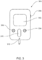
- a display assembly which may be similar to the one shown in FIGS. 1A . 1D and 1F , or may be larger or smaller, is included on a controller or companion device. An embodiment of the controller or companion device is shown in FIG. 3 .
- Infusion pump assembly 100 may include a display system 104 that may be visible through the enclosure assembly 102.
- One or more switch assemblies input devices 106, 108, 110 may be positioned about various portions of the enclosure assembly 102.
- the enclosure assembly 102 may include infusion port assembly 112 to which cannula assembly 114 may be releasably coupled.
- a removable cover assembly 116 may allow access to a power supply cavity 118 (shown in phantom on FIG. 1D ).
- infusion pomp assembly 100 may include processing logic (not shown), which may be referred to as the pump processor, that executes one or more processes that may be required for infusion pump assembly 100 to operate properly
- Processing logic may include one or more microprocessors (not shown), one or more input / output controllers (not shown), and cache memory devices (not shown).
- One or more data buses and/or memory buses may be used to interconnect processing logic with one or more subsystems.
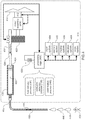
- at least one of the subsystems shown in FIG. 4 is also included in the embodiment of the infusion pump assembly 200 shown in FIGS. 2A-2D.
- examples of the subsystems interconnected with processing logic 400 may include but are not limited to memory system 402. input system 404. display system 406. vibration system 408, audio system 410 motor assembly 416, force sensor 412, temperature sensor (not shown) and displacement detection device 418 (which may be referred to as a device to determine and or detect the distance the plunger has moved with respect to the syringe barrel/syringe).
- Infusion pump assembly 100 may include primary power supply 420 (e.g. a battery) configured to be removable installable within power supply cavity 118 and to provide electrical power to at least a portion of processing logic 400 and one or more of the subsystems (e.g.. memory system 402. input system 404, display system 406, vibration system 408, audio system 410, motor assembly 416, force sensor 412, and displacement detection device 418).
- primary power supply 420 e.g. a battery
- Infusion pump assembly 100 may include reservoir assembly 430 configured to contain infusible fluid 422.
- reservoir assembly 430 may be a reservoir assembly similar to that described in U.S. Patent No. 7,498,563, issued March 3, 2009 and entitled Optical Displacement Sensor for Infusion Devices, and/or as described in U.S. Patent No. 7,306,578, issued December 11, 2007 and entitled Loading Mechanism for Infusion Pump; PCT Application Serial No.
- the reservoir assembly may be any assembly in which fluid may be acted upon such that at least a portion of the fluid may flow out of the reservoir assembly, for example, the reservoir assembly, in various embodiments, may include but is not limited to: a barrel with a plunger, a cassette or a container at least partially constructed of a flexible membrane.
- Plunger assembly 424 may be configured to displace infusible fluid 422 from reservoir assembly 430 through cannula assembly 450 (which may be coupled to infusion pump assembly 100 via infusion port assembly 424) so that infusible fluid 422 may be delivered to user 454.
- plunger assembly 424 is shown to be displaceable by partial nut assembly 426, which may engage lead screw assembly 428 that may be rotatable by motor assembly 416 in response to signals received from processing logic 400.
- the combination of motor assembly 416, plunger assembly 424, partial nut assembly 426, and lead screw assembly 428 may form a pump assembly that effectuates the dispensing of infusible fluid 422 contained within reservoir assembly 430.
- partial nut assembly 426 may include but is not limited to a nut assembly that is configured to wrap around lead screw assembly 426 by e.g., 30 degrees.
- the pump assembly may be similar to one described in U.S. Patent No. 7,306,578, issued December 11 , 2007 and entitled Loading Mechanism for Infusion Pump; U.S. Patent Application Serial No.12/249,882, filed October 10, 2008 and entitled Infusion Pump Assembly, now U.S.
- screens may be referenced with respect to the "pump” or “Companion” or “Controller”. However, in various embodiments, a similar screen or a similar method may be accomplished on another device. For example, where the screen or method is referenced with respect to the "pump”, a similarly functional screen or method may be used on the "Companion” or “Controller” in other embodiments.
- a similarly functional screen or method may be used on the “Companion” or “Controller” in other embodiments.
- this description includes embodiments related to both pumps having displays and pumps having no displays, it should be evident that where the embodiment includes an infusion pump without a display, any screens will be visible on a Companion or Controller.
- the interaction may be accomplished via a switch assembly on the pump where the pump is an infusion pump without a display.
- Processing logic which in some embodiments, includes at least one element as shown in described with respect to FIG.4 , is used to receive inputs from a user or caregiver.
- the user or caregiver uses one or more input devices or assemblies, including but not limited to, one or more of the following: button / switch assembly, slider assemblies, including, but not limited to, capacitive sliders (which may include, for example, including but not limited to any slider described in U.S. Patent Application Serial No.11/999,268, filed December 4, 2007 and entitled Medical Device Including a Slider Assembly, now U.S. Publication No. US-2008- 0177900, published July 24, 2008 ;and entitled Medical Device Including a Slider Assembly, jog wheel and/or touch screen.
- button / switch assembly slider assemblies, including, but not limited to, capacitive sliders (which may include, for example, including but not limited to any slider described in U.S. Patent Application Serial No.11/999,268, filed December 4, 2007 and entitled Medical Device Including a Slider Assembly, now U.S
- the infusion device additionally received inputs from internal systems, including but not limited to occlusion detection process 438, confirmation process 440, volume measurement technology (e.g., acoustic volume sensing). Using these inputs, the infusion device produces outputs, for example including, but not limited to, infusion fluid delivery to the user or comments, alerts, alarms or warnings to the user.
- the inputs are thus either directly from the user to the pump, directly from the pump systems to the processing logic, or from another device, e.g., a remote controller device (described in more detail below), to the pump.
- the user or caregiver interaction experience thus includes, but is not limited to, one or more of the following: interaction with a display (either on the infusion pump device itself or a remote controller device or both), which includes but is not limited to, reading/seeing text and/or graphics on a display, direct interaction with a display, for example, through a touch screen, interaction with one or more buttons, sliders, jog wheels, one or more glucose strip readers, and sensing either through touch sensation or audio, one or more vibration motors, and/or an audio system.
- a display either on the infusion pump device itself or a remote controller device or both
- direct interaction with a display for example, through a touch screen
- interaction with one or more buttons, sliders, jog wheels, one or more glucose strip readers and sensing either through touch sensation or audio, one or more vibration motors, and/or an audio system.
- the term "user interface” is used to encompass all of the systems and methods a user or caregiver interacts with the infusion pump, to control the infusion pump.
- the infusion pump may be remotely controlled using a remote controller assembly 300, also referred to as a controller or a companion.
- Remote control assembly 300 may include all, or a portion of, the functionality of the infusion pump assembly shown in FIGS. 1A-1F , itself.
- the infusion pump assembly (not shown, see FIGS. 1A-1F , amongst other FIGS.) may be configured via remote control assembly 300.
- the infusion pump assembly may include telemetry circuitry (not shown) that allows for communication (e.g., wired or wireless) between the infusion pump assembly and e.g., remote control assembly 300, thus allowing remote control assembly 300 to remotely control infusion pump assembly 100.
- Remote control assembly 300 (which may also include telemetry circuitry (not shown) and may be capable of communicating with infusion pump assembly) may include display assembly 302 and an input assembly, which may include one or more of the following: an input control device (such as jog wheel 306, slider assembly 310, or another conventional mode for input into a device), and switch assemblies 304, 308.
- an input control device such as jog wheel 306, slider assembly 310, or another conventional mode for input into a device
- switch assemblies 304, 308 switch assemblies 304, 308.
- jog wheel 306 may include only one of either jog wheel 306 or slider assembly 310, or another conventional mode for input into a device.
- jog wheel 306 may include a wheel, ring, knob, or the like, that may be coupled to a rotary encoder, or other rotary transducer, for providing a control signal based upon, at least in part, movement of the wheel, ring, knob, or the like.
- Remote control assembly 300 may include the ability to pre-program basal rates, bolus alarms, delivery limitations, and allow the user to view history and to establish user preferences. Remote control assembly 300 may also include a glucose strip reader 312.
- remote control assembly 300 may provide instructions to the infusion pump assembly via a wireless communication channel established between remote control assembly 300 and the infusion pump assembly. Accordingly, the user may use remote control assembly 300 to program configure the infusion pomp assembly. Some or all of the communication between remote control assembly 300 and the infusion pump assembly may be encrypted to provide an enhanced level of security
- the user interface may require user confirmation and user input.
- the exemplary embodiments of the user interface are centered on ensuring the user knows the effect of various interactions on the pump. Many examples will be presented throughout this description of the pump communicating the result of the user's actions to the user. These features ensure the user understands their actions and therefore, imparts greater safety onto the user.
- One such example is throughout the exemplary embodiment of the user interface, where the user presses the back button on a screen after a value has been changed, the user interface displays the Cancel Changes confirmation screen, as shown in FIG. 6.
- the user interface discards any pending changes, closes the confirmation screen and goes back to the previous screen (i.e., the screen previous to the screen where the user pressed the Back button).
- the action selection is "No" on the "Cancel Changes?" confirmation screen
- the user may wear the infusion pump either attached to a belt, attached to another article or clothing or a garment such that the device is worn on the body, or, in some embodiments, attached to an undergarment, in a pocket or, in some embodiments, attached to the skin of the user.
- the user generally wears the infusion pump as close to twenty-four (24) hours a day as possible, and in some cases, removing the device for short periods of time, for example, but not limited to, during an MRI or other treatment that may effect the device and/or while showering/bathing.
- the infusion pump may be exposed to various temperatures, including, temperature swings, which may include positive temperature swings and/or negative temperature swings. These temperature swings may be the result of the user stepping out of doors, into a cold room, into a hot room and/or under a blanket or other warming agent.
- the fluid contained in the reservoir while in the pump which, as discussed above, may include, but is not limited to insulin, has a thermal expansion coefficient which may be referred to as a general volumetric thermal expansion coefficient.
- a thermal expansion coefficient which may be referred to as a general volumetric thermal expansion coefficient.
- the fluid, or insulin will expand or contract.
- Various factors may contribute to the expansion or contraction of the fluid including but not limited to the rate of change of the temperature.
- the amount of expansion or contraction may be a function of the temperature.
- the components of the pumps also have thermal expansion coefficients. These thermal expansion coefficients may vary depending on the material. Thus, where the various components are made from different materials. the thermal expansion coefficients may vary.
- a change in temperature may affect a thermal expansion or thermal contraction of the fluid and/or one or more components of the infusion pump.
- an increase in temperature may cause an increase in the diameter of the reservoir / syringe 430 (for illustration only, please refer to FIG. 4 ). This may be because the relative thermal expansion of the syringe compared with the fluid governs whether fluid is delivered or pulled back. Thus, this in turn may cause any fluid/insulin in the cannula 450 to flow backwards, towards the reservoir 430. In this case, a volume of fluid/insulin is pulled back into the reservoir. Thus, a subsequent request for a delivery by processing logic 400 may only result in this retracted volume being delivered to the user.
- a volume of fluid-insulin (the retracted volume) has not been delivered to the user without request or knowledge by the user.
- Another example includes temperature decrease.
- a temperature decrease may cause the reservoir 430 to decrease in diameter, causing fluid-insulin to flow to the cannula 450.
- an unintended bolus volume is delivered to this user.
- fluid-insulin has been delivered to the user without request or knowledge by the user.
- the user may receive less fluid/insulin than is required or requested and thus, may experience hyperglycemia.
- the user may receive more fluid/insulin than is required or requested and thus, may experience hypoglycemia.
- the user receives a fluid/insulin volume that is not the same as the requested or programmed therapy and is not notified of the disparity
- the reservoir is assumed to be a cylinder.
- a mathematical model of the change in volume of a cylinder (assuming a constant coefficient of linear expansion, ⁇ ). This is a model for explanation purposes. Additional mathematical models may be determined to accommodate additional assumptions, for example, a shape other than a cylinder, or a syringe with a movable plunger.
- ⁇ V V 3 ⁇ T + 3 ⁇ 2 ⁇ T 2 + ⁇ 3 ⁇ T 3
- the change in specific volume for water between 30 C and 10 C is about 0.40%.
- the difference between the two (about 0.12%) applied to a 3 cc syringe or reservoir would be about 3.6 ⁇ L .
- the syringe plunger may move in response to the thermal expansion depending on the plunger material and the relationship of the syringe in the pump (e.g.. the design of the syringe retention in the pump).
- the systems, methods and apparatus described to minimize the effect of temperature on the thermal expansion of the fluid and/or one of more of the components of the infusion pump may include one or more of the following exemplary embodiments.
- selection of materials with predictable and favorable thermal expansion coefficients may minimize the potential under and over delivery of fluids as discussed above.
- the syringe material for example, may be selected to match the thermal expansion of the fluid.
- the linear expansion coefficient for water at about 20 C is about: 68.9 ⁇ 10 ⁇ 6 cm cm ⁇ K
- the syringe material may be selected to have an expansion coefficient close to this value.
- a blend of polycarbonate and acrylonitrile butadiene styrene also referred to as "ABS”
- ABS acrylonitrile butadiene styrene
- other plastics for example, but not limited to, polycarbonate, may be close to the correct expansion coefficient such that the volume delivered by the syringe pump due to the expected temperature change is minimal and/or acceptable.
- the plastic or material selected may be tailored to the slope of the thermal expansion of the fluid.
- the material of the plunger and or the plunger rod may be selected to thermally differentially compensate for the change in temperature. In some embodiment the materials for the syringe, plunger and plunger rod may be selected to thermally differentially compensate for the change in temperature. Also, or in addition to, in some embodiments, the material of one or more components of the drive train, or any other component of the infusion pump, may be selected to thermally differentially compensate for the change in temperature.
- the materials for any one or more infusion pump components may be selected to have an opposite thermal coefficient, or a thermally compensating material to minimize the thermal expansion effects of the temperature.
- the flow of fluid may be negative.
- at least one component of the drive train may have a negative thermal constant thus, having the opposite thermal coefficient
- the syringe does not experience a change in volume.
- the use of a material which may undergo a phase change during a temperature change event may minimize the effect of the temperature differential-change on the infusion pump.
- the plunger may include a predetermined volume of wax, thus, as the temperature increases, the length or position may increase due to the phase change of the wax. Additional wax features may be added in some embodiments to prevent flow.
- a wax feature may be added to move the plunger forward a (predetermined) distance such that the resulting change in the volume is equal to the square root of the diameter of the plunger
- the use of a material which undergoes a phase change in response to temperature/temperature change/differential may be used to compensate for the change of volume of the syringe due to a temperature change.
- the material which undergoes a phase change in response to a temperature change may absorb the energy of the thermal differential, thus, for example, where the temperature is increasing, rather than rising the temperature of the infusion pump, the wax, or other phase change material, may melt the wax/phase change material, thus, acting as an energy sink and absorbing the heat.
- the syringe may be constrained in such a way that a change in temperature may cause the plunger to be advanced or withdrawn to compensate for the volume change of the syringe.
- the syringe may be held in a metal case, the metals that may be used include but are not limited to, steel, aluminum, and/or any metal with a low coefficient of thermal expansion, which may include, but is not limited to, FeNi36, also known as INVAR®.
- the plunger may be made from a material that has a high coefficient of thermal expansion.
- a decrease in temperature may cause the syringe plunger to be withdrawn as the diameter of the syringe barrel is decreasing.
- the change in the total volume may be minimized.
- characterizing the effect of a change in temperature on the volume of fluid pumped by the infusion device may be completed
- the pump may be subjected to temperature variation (i.e., both positive and negative) and the corresponding response by the infusion pump may be recorded.
- the characterization may include, but is not limited to, varying rates of change (i.e.. 1 degree Celsius per minute, and whether positive and negative, etc), total temperature variation (e.g.. 10 degrees Celsius, 5 degrees Celsius, etc), and or position of syringe plunger.
- the infusion pump may include one or more devices and/or components and/or systems to determine the temperature, In some embodiments, the infusion pump may include one or more thermistors or other temperature sensors to determine the temperature However, in other embodiments, various methods and/or devices and/or systems to determine the temperature, either directly or indirectly, may be used, including, but not limited to, one or more of the following; at least one resistance temperature device (RTD) and/or at least one non-contact infrared device (non-contact IR). The location of the one or more thermistors and/or temperature determination devices may vary.
- RTD resistance temperature device
- non-contact IR non-contact infrared device
- the locations of one of more of the thermistors and/or temperature determination devices may include, but is not limited to, the drive screw, any location on the drive train, on the syringe barrel, including but not limited to, printed on the syringe barrel, the plunger and/or, the printed circuit board.
- the one or more themristort(s) and/or temperature determination devices location may be any where away from the heat sources that would render a potentially false reading.
- the one or more thermistors may determine the temperature of one or more locations, including, but not limited to, inside of the syringe, the outside of the syringe, the inside of the pump, and or the outside of the pump.
- Various controls may be determined based on a temperature model in any one or more of these locations.
- the characterization may be made by taking temperature readings both within the syringe and outside of the syringe.
- the characterization may be performed by taking temperature readings from outside the pump and inside the pump.
- the one or more thermistors and/or temperature determination devices are preferably placed in the same location on the pump for use by the user as they were during the characterization.
- the characterization may be completed by measuring the volume of fluid delivered as a function of temperature. In some embodiments, this may be accomplished by using a thermal chamber and an infusion set / cannula connected to the reservoir / syringe delivering fluid to a precision scale. However, in other embodiments, this may completed by using a thermal chamber and an infusion set/cannula connected to the reservoir/syringe delivering fluid, and following, determining the position of the plunger inside the reservoir to determine the total volume of fluid delivered.
- the temperature of the pump in one or more locations and /or taken by one or more thermistors
- the target position of the plunger may vary as a function of temperature to compensate for the thermal expansion of the syringe and/ or the plunger.
- the thermal expansion reading may be determined by referencing the characterization data, as discussed above.
- the target position may be modified based on a look-up table or function approximation of the volume change of the syringe with temperature.
- the infusion pump delivers fluid either as a basal or a bolus delivery, and/or a variety thereof.
- the basal delivery is a programmed rate or volume per hour.
- the infusion pump delivers a volume of fluid at preset intervals for preset durations of time.
- the infusion pump may also deliver bolus volumes.
- a bolus is a requested volume of fluid delivered immediately, i.e., at the time the request is made.
- One embodiment of the bolus and basal delivery methods is described in PCT Application Serial No. PCT/US2009/060158, filed October 9, 2009 and entitled Infusion Pump Assembly, now Publication No. WO 2010/042814, published April 15, 2010 and entitled Infusion Pump Assembly; and U.S.
- the infusion pump may determine the distance the plunger must move to deliver a volume of fluid, e.g., a basal volume or a bolus volume.
- the infusion pump may confirm the distance the plunger moved during a delivery using an optical displacement sensor.
- the infusion pump determines the number of motor encoder counts per delivery and confirms movements of the plunger.
- the delivery method includes a determination of the distance the plunger should move (which may be referred to as the target plunger position) to deliver the desired/target volume. As discussed above, this may be done by determining the number of motor encoder steps, and m other embodiments, may be another method. Regardless, the infusion pump makes a determination or plunger distance movement.
- the first step may be to characterize the volume delivered as the temperature changes.
- This volume may be a function of the amount of fluid contained in the syringe, call this V, and, due to variations in the thermal expansion properties of plastics and liquids/fluids, also, a function of the temperature, call this T.
- the coefficient ⁇ ( T ) may be approximated as a constant, found as a function of temperature (as shown above) or possible found as a function of both temperature and plunger position ⁇ ( T , x ).
- the target plunger position may be determined and adjusted.
- this correction may be performed in different ways, including, but not limited to, the following.
- the correction may be done by delivering on an interval which may be more frequent than the basal delivery interval, which may be, but is not limited to, one delivery every e.g., 3 minutes, but in other embodiments, may be more frequent or less frequent
- the position of the syringe may be adjusted based on the temperature change, maintaining a zero net volume delivered between regular deliveries. e.g., basal and/or bolus deliveries. In some embodiments, this may be used for low basal rates, where the thermally driven volume may exceed the regularly scheduled basal delivery. This may, however, in some embodiments, require reversing the syringe direction to prevent delivery.
- Another embodiment may include applying the correction when the fluid/insulin is scheduled for delivery.
- the target plunger position may be corrected based on the measured temperature change aud estimated thermally-driven volume delivery.
- the correction may be limited such that the plunger may only be driven in one direction.
- modeling may vary, and an assumption may be made with respect to both length and diameter of the syringe.
- assumption may be made regarding the effect of temperature on the thermal expansion coefficient of one or more components of the infusion pump, including, but not limited to, the drive train, plunger, plunger rod, infusion pump housing, and cannula.
- adjusting the plunger target may include adjusting the target so that it is closer to the exit of the syringe, or further away from the exit of the syringe.
- the plunger advancement may be modified.
- the plunger may be driven backwards to compensate for temperature, However, in some embodiments, depending on the infusion pump, it may be desired to limit adjustment to closer to the exit of the syringe, This may be due to the potential for backlash.
- a temperature dependant basal rate may be preprogrammed to the pump for temperature compensation.
- the pump processor receives data from at least one temperature sensor. If the temperature data indicates that the temperature is such, or that the rate of change of temperature is such, that an adjustment should be made, the processor may signal to alter the preprogrammed basal rate. In some embodiments, this alteration may be either an additional or a decrease of the basal rate by a preset percentage, for example, an increase of 30% or a decrease of 15%. Of course, these are only examples, and in these embodiments, the preset alterations may be determined to be different from those stated.
- the infusion pump may include at least one temperature sensor and at least one optical sensor.
- the optical sensor may be used to determine that the plunger advanced.
- the distance of advancement may also be determined
- a small reflective optical sensor (hereinafter "optical sensor") that fits into the form factor of the infusion pump hardware is used.
- the optical sensor has a sensing range that overlaps with the plunger displacements.
- any optical sensor may be used, including, but not limited to a Sharp GP260, manufactured by Sharp Electronics Corporation which is a U.S. subsidiary of Sharp Corporation of Osaka, Japan. This optical sensor contains an infra red emitting diode and infra red sensing detector in a single package.
- Light from the emitter is unfocused and bounces off the sensing surface, some of which makes it back to the detector resulting in the sensed intensity of light that varies as a function of distance/angle to the reflector.
- the sensor is placed such that the reflective surface is the plunger.
- an optical sensor may be used to determine the level of fluid in the syringe/reservoir. This information may be used to determine whether the plunger rod has advanced. Together with the temperature sensor information, this may provide added data/information to determine a temperature dependant change.
- the infusion pump may include an optical displacement sensor This sensor may be used to determine whether the plunger rod has advanced, either forward or backwards, and the distance of the advancement. Using this displacement information, together with the information from the one or more temperature sensors, the effect of the temperature change on the plunger may be determined. In turn, this determination may increase the accuracy of controls used to compensate for a temperature change. This may include, but is not limited to, decreasing the amount of fluid delivered due to a sensed forward movement and/or increasing the amount of fluid delivered due to a sensed backwards movement. In either case, the increase and/or decease of the basal rate and or amount and or the amount of bolus (for example, by a percentage of the amount intended) is by a predetermined amount and for a predetermined time.
- the infusion pump system may include a system and/or method for adjusting the basal rate and /or bolus amount based on a temperature change
- the system may automatically, and/or by request and/or confirmation by the user, enter a mode having a limited period, e.g., a flat pre-set limited time period. e.g., 20 minutes, and/or in some embodiments, the mode may continue until the temperature change threshold is not longer applicable.
- the infusion pump processor may be pre-programmed with a "decreasing gradient" mode, and the infusion pump may purposefully under deliver in this mode, i.e.. an automatic percentage decrease in the basal rate, and, in some embodiments, also, the bolus, may be instituted to compensate for a predicated additional delivery of fluid.
- determining the percentage change of insulin delivery may depend on the characterization of the infusion pump.
- the infusion pump processor may be pre-programmed with a increasing temperature gradient" mode, and the infusion pump may purposefully over deliver, i.e., an automatic percentage increase in the basal rate, and, in some embodiments, also the bolus, may be instituted to compensate for the predicated decrease in delivery of fluid. As discussed above, determining the percentage change may depend on the characterization of the infusion pump.
- the term "advanced” refers to the movement of a plunger within a syringe or reservoir body. Advancement is not limited to movement in a particular direction.
- the syringe has an exit end, which is the end of the syringe in which fluid moves outward from the syringe.
- the system may include one or more devices and / or sensors to determine the effect of the temperature on the syringe/phunger and/or the pumping of fluid, either towards the user/cannula or away from the user/cannula
- These devices and/ or sensors may include, but are not limited to, one or more flow sensors, one more occlusion devices and/or one or more binary valves, and/or one or more strain beams or sensors and /or one or more optical sensors and/or one or more temperature sensors and/or one or more ultrasonic range sensors and or one or more potentiometers and/or one or more rotor encoders and or one or more linear encoders.
- the infusion pump may include at least one temperature sensor and at least one optical sensor.
- the optical sensor may be used to determine that the plunger advanced. In some embodiments, the distance of advancement may also be determined.
- a small reflective optical sensor hereinafter “optical sensor” that fits into the form factor of the infusion pump hardware is used.
- the optical sensor has a sensing range that overlaps with the plunger displacements. In various embodiments any optical sensor may be used, including, but not limited to one or more of the following: Sharp GP2S60, Sharp GP2S700 and Sharp GP2A240LC, all of which are manufactured by Sharp Electronics Corporation which is a U.S.
- This optical sensor contains an infra red emitting diode and infra red sensing detector in a single package. Light from the emitter is unfocused and bounces off the sensing surface, some of which makes it back to the detector resulting in the sensed intensity of light that varies as a function of distance/angle to the reflector. In some embodiments, the sensor is placed such that the reflective surface is the plunger.
- an optical sensor may be used to determine the level of fluid in the syringe / reservoir. This information may be used to determine whether the plunger rod has advanced. Together with the temperature sensor information, this may provide added data/ information to determine a temperature dependant change.
- the infusion pump may include an optical displacement sensor. This sensor may be used to determine whether the plunger rod has advanced, either forward (towards the syringe exit) or backwards (away from the syringe exit), and the distance of the advancement. Using this displacement information, together with the information from the one or more temperature sensors, the effect of the temperature change on the plunger may be determined. In turn, this determination may increase the accuracy of controls used to compensate for a temperature change.
- This may include, but is not limited to, decreasing the amount of fluid delivered (i.e., decreasing the volume of fluid that was scheduled to be delivered, i.e., basal rate, or requested to be delivered, i.e., bolus amount) to a sensed forward movement and / or increasing the amount of fluid delivered due to a sensed backwards movement.
- decreasing the amount of fluid delivered i.e., decreasing the volume of fluid that was scheduled to be delivered, i.e., basal rate, or requested to be delivered, i.e., bolus amount
- the infusion pump includes an exit valve and /or an occluder.
- the infusion pump includes at least one device to prevent the delivery of fluid either from the syringe to the cannula and / or from the cannula to the user.
- the device is activated when the at least one temperature sensor sends a signal to the processor and the processor determines that the temperature change meets a threshold, i.e., that the temperature change is large enough to effect a change in delivery due to temperature. In some embodiments, this may activate the occluder and / or exit valve, preventing fluid from flowing into or out of the syringe and / or the cannula.
- the occluder and / or exit valve device is deactivated when the at least one temperature sensor sends a signal to the processor and the processor determines that the temperature change no longer meets a threshold, i.e., that the temperature change is no longer large enough to effect a change in delivery due to temperature. In some embodiments, this may deactivate the occluder and / or exit valve, allowing fluid to flow out of the syringe and / or to the cannula and /or to the user.
- the plunger target may be adjusted in response to the information from one or more temperature sensors.
- the occluder / exit valve may be closed during the interval when the infusion pump is not actively delivering fluid so as to prevent inadvertent fluid flow in or out of the syringe / reservoir due to a change in temperature.
- the at least one temperature sensor may continue to send signals to the processor indicating temperature. This information may be used by the control system to determine whether and how to modify the "next delivery" of fluid, i.e., the next plunger target. Thus, when the "next delivery" is made, the occluder / exit valve may open and the fluid is delivered.
- the occluder / exit valve may act primarily to prevent spontaneous unintended fluid flow that may be caused by temperature change.
- the control system may adjust the volume delivery, i.e., plunger target, based on the temperature change such that the volume of delivered fluid compensates for the temperature change.
- the infusion pump may include a compliant component.
- the compliant component may allow the difference in volume change in the syringe / reservoir while maintaining a pressure constant.
- controller compensation may not be necessary to compensate for temperature change when the occluder/ exit valve is open as there would not be a pressure build up from a change in temperature.
- the occluder / exit valve may be closed and the plunger rod may be allowed to float, i.e., the plunger rod may become disengaged with the drive train.
- a change in pressure would thus allow the plunger to float and find equilibrium, thus adjusting without the need for controller compensation in response to a temperature change.
- the infusion pump includes at least one flow sensor, including, but not limited to, a flow sensor positioned in the exit fluid path.
- the flow sensor may detect the flow of fluid. This information may be correlated with delivery instructions and a determination may be made whether the fluid delivered was requested and / or a proper delivery. In some embodiments, where flow is detected and it is determined thai the fluid delivered was not requested and/or not a proper delivery, the occluder and or exit valve may be closed.
- a flow sensor may determine fluid flow, either inward or outward, and where this is not an expect event, the infusion pump may activate at least one mechanism, including, but not limited to, an occluder and/or a valve to prevent the continued flow of fluid.
- the flow information may be used to determine the amount or volume of fluid that has been delivered or has flowed inward and this information may be used to alter the plunger target during the next scheduled or requested delivery (e.g.. basal or bolus), or, in some embodiments, may be used to alter the delivery schedule. In some embodiments, this may be completed without user interaction. In some embodiments, an alert may be sent to the user and the user must accept the proposed course or action to alleviate the under or over delivery of fluid.
- the infusion pump may include one or more optical sensors These sensors may be placed in the infusion pump to determine the level of fluid in the syringe/reservoir.
- the one or more optical sensors may determine the level of fluid before the processor signals the drive train to advance the plunger and after. Thus, the volume difference may be determined before and after the plunger is advanced.
- the at least one optical sensor may, in some embodiments, collect data a preset intervals, regardless or whether the drive train has been activated.
- the at least one optical sensor may collect information to determine when and whether the plunger has advances and/or when and whether fluid has been delivered or pulled in.
- the at least one optical sensor may collect data for the processor to determine when a non-requested delivery event may have occurred.
- the processor may correlate this information with the at least one temperature sensor and thereby determine whether the infusion pump is experiencing a temperature related effect. In some embodiments, the processor may alert the user. In some embodiments, the information may be used to instigate a control algorithm to compensate for the temperature change effect using, for example, but not limited to, the various embodiments discussed herein.
- a strain beam may be used to identify a plunger moving away from the exit of the syringe.
- the strain beam may be positioned relative to the plunger rod such that where the plunger rod begins to move away from the syringe exit, the strain beam will sense the strain.
- the infusion pump includes a strain beam that may be used to detect and or identify occlusions
- the strain beam and methods may be, in some embodiments, similar to those described in U.S. Patent Application Serial No.12/249,882, filed October 10, 2008 and entitled Infusion Pump Assembly, now U.S. Publication No. US-2010-0094222, published April 15, 2010 and entitled Infusion Pump Assembly; and PCT Application Serial No.
- a strain beam may determine whether a particular temperature change has resulted in plunger movement. Where plunger movement is detected due to a temperature change, the infusion pump may alert the user. In some embodiments, the system may correlate a change in strain with a change in temperature.
- one or more various apparatus and/or systems may be employed to maintain the temperature of the infusion pump.
- the infusion pump includes a heater device.
- the heater device may receive instructions from the processor.
- the heater device may be located anywhere in or on the infusion pump, however, in some embodiments, the heater device is located within the infusion pump housing.
- the heater device is powered by a power source or battery inside the infusion pump. However, in some embodiments, the power source may be outside the infusion pump.
- the heater source may be any heating source desired, however, in the exemplary embodiment, the heating source may be a KAPTON® (Polyimide Film) Heater kit, part number KH-KIT-EFH- 15001 and available from omega.com ®.
- at least one temperature sensor is located in or on the infusion pump. The at least one temperature sensor communicates information to the processor. Based on the temperature sensor data, the processor may act as a thermostat and power the heater source to maintain the temperature in the infusion pump at a desired temperature.
- the desired temperature may be between 15 and 30 degrees Celsius, but in other embodiments, the maintenance temperature may be different. In some embodiments, it may be desirable to maintain the temperature at the higher end.
- the syringe/reservoir may be contained in a metal case in the infusion pump.
- the metal case may increase the conduction of heat between the heater element and the syringe reservoir.
- the at least one heater element may be located in one or more locations inside the infusion pump and one or more of these locations may be selected to maintain the temperature of one or more components of the infusion pump, including, but not limited to, the syringe, fluid, plunger, housing, plunger rod and or the drive train.
- the at least one heater elements may additionally increase the power source and / or battery life in the infusion pump. Maintaining the temperature at or about 35 degrees Celsius may be beneficial to battery life and / or performance.
- a hook and loop system fastener system for example, but not limited to one offered by VELCRO® USA Inc. of Manchester. NH, may be utilized to allow for easy attachment / removal of an infusion pump from the user. Accordingly, an adhesive patch may be attached to the skin of the user and may include an outward facing hook or loop surface. Additionally, a surface of infusion pump 114 may include a complementary hook or loop surface. Depending upon the separation resistance of the particular type of book and loop fastener system employed, it may be possible for the strength of the hook and loop connection to be stronger than the strength of the adhesive to skin connection. Accordingly, various hook and loop surface patterns may be utilized to regulate the strength of the hook and loop connection.
- FIGS. 10A-10E five examples of such hook and loop surface patterns are shown. Assume for illustrative purposes that one surface of infusion pump housing is covered in a "loop" material. Accordingly, the strength of the hook and loop connection may be regulated by varying the pattern (i.e., amount) of the "hook" material present on the surface of adhesive patch. Examples of such patterns may include but are not limited to: a singular outer circle 220 of "hook" material (as shown m FIG. 10A ); a plurality of concentric circles 222, 224 of "hook” material (as shown in FIG. 10B ): a plurality of radial spokes 226 of "hook” material (as shown in FIG.
- a holder, pouch, sack, container or other type of housing may be sized to accommodate an infusion pump.
- the holder may be constructed to include multiple layers including but not limited to, one or more insulating layers.
- one or more of the layers may include a fabric that when wetted and refrigerated or frozen, the layer provides a cooling effect. This layer may be desired in warmer climates or in situations where the user's infusion pump may be exposed to the sun or a warm environment.
- the one or more layers of material may be highly absorbent material.
- the holder may include one or more canisters of isopropyl alcohol which may, when deployed, be absorbed into the highly absorbent material of the holder and provide evaporate e cooling to the infusion pump.
- the holder may include alternative and/or additional methods, systems and or devices for cooling the infusion pump.
- the holder may include one or more temperature measurement devices and/or temperature sensors that may transmit information to the infusion pump and/or a controller
- the one or more temperature sensors may communicate the temperature of the holder and either deploy the one or more canisters of alcohol and or alert the infusion pump user/controller and / or turn o the heating source, based on the temperature sensor.
- the heating and/or cooling may be triggered by reaching a threshold change in temperature.
- the holder may provide for a closed-loop system for maintaining the temperature for the infusion pump.
- the holder 500 include an outside layer 502, an inside layer 504 and an inner pocket 506.
- the pocket 506 may include additional cushion or insulation to both protect the infusion pump from outside forces and or temperature change.
- the holder 500 may include a fastener along the front, top or the side.
- the holder 500 may include the holder may include a pull down flap (not shown) on the front to expose the screen and / or input assemblies (e.g., including but not limited to buttons, sliders, and / or jog wheels).
- the flap may be secured closed using a book-and-loop system.
- the flap may be secured using any other fastener system including, but not limited to, snaps, buttons, magnetic closures and zippers.
- the holder 500 may be attached to a strap 508 designed to be attached to the user (see FIG. 12 for example).
- the strap 508 may be elastic and/ or adjustable and may include at least one closure device.
- the holder may include a clip 512 which may be referred to as a "belt-clip" or another type of clip configured such that it securely and removably fits over a belt, handle, piece of clothing or other.
- the holder 500 may additionally include an opening 514 for tubing 516 to fit through.
- the infusion pump (not shown) may be contained inside the holder 500 and the holder worn close to the insertion site (not shown) on the user such that minimal tubing 516 is exposed to the outside temperature.
- embodiments of the holder 500 including an opening 514 for tubing may be beneficial for maintaining the temperature of the tubing 516 and / or the fluid in the tubing.
- a plastic material for example, a Press n' Seal, or another material of similar behavior, may be used to attach and maintain the infusion pump against the user's body.
- a cuff or band fitted against the leg, midsection or arm, for example, of a user may include a pouch for the infusion pump.
- the infusion pump may be maintained in position against the skin through inner pockets, bra pockets, etc.
- various embodiments are described herein for both utilizing the user's body heat and / or a heating element to maintain the temperature of the infusion pump.
- additional devices and apparatus are within the scope of the invention.
- various methods, systems and apparatus for maintaining the temperature of an infusion pump may include at least one temperature sensor.
- Described herein are various methods, systems, devices and / or apparatus for maintaining the temperature of an infusion pump. Inherent in at least some of these embodiments is the maintenance of the infusible fluid / insulin temperature. It is well know that manufacturers of insulin recommend that the temperature of insulin not exceed a high and a low temperature. Additionally, it may be beneficial to maintain fast-acting (e.g., HUMALOG ®, NOVOLOG ®) at room/ambient temperature (e.g.
- the manufacturer recommends storing insulin in a refrigerated area, e.g., between 2.2 and 7.8 °C (36 and 46 degrees Fahrenheit), until the vial is used. From that point on, it is recommended that the vial be stored at room temperature.
- insulin may be less effective or not effective once it has reached a non-recommended temperature, it may be beneficial for a user to know whether the insulin has been properly stored, whether while in transit, in the refrigerator or while in use.
- a stick-on temperature gauge 520 may be placed on a vial 522 of fluid, and in some embodiments, on a vial of insulin.
- the gauge may tell the user the current temperature of the vial.
- the temperature may be indicated as various shades of red and blue, indicating various temperatures towards the high and low range.
- the gauge becomes non-reversible, thus indicating instantly to the user that the insulin has reached either a maximum or minimum temperature.
- Any stick-on temperature gauge may be used including a non-reversible temperature label such as a Non-Reversible Temperature Labels, 3 Temperature Ranges, part number TL-3 available from omega.com®, or another similar temperature label.
- a Reversible Temperature Label may be used or a label with both reversible and non-reversible components.
Claims (6)
- Système pour pompe à perfusion comprenant :une seringue (430) possédant une extrémité de sortie et un piston mobile à l'intérieur de la seringue ;au moins un dispositif de détermination de température permettant de déterminer la température à l'intérieur de la seringue et/ou à l'extérieur de la seringue ;au moins un dispositif pour détecter l'effet d'un changement de température sur le mouvement du piston, ledit dispositif comprenant un capteur de déplacement optique permettant de détecter le déplacement du piston ;un processeur de pompe (300, 400) en communication avec l'au moins un dispositif de détermination de température et l'au moins un dispositif pour détecter l'effet d'un changement de température sur le mouvement du piston, etun obturateur/une soupape de sortie situé(e) en aval de la sortie de seringue, ledit obturateur/ladite soupape de sortie bloquant un trajet d'écoulement ;caractérisé en ce que le système de pompe comprend en outre un capteur de débit situé en aval de la sortie de seringue ; etle processeur de pompe (300, 400) étant adapté, une fois que le dispositif de détermination de température a déterminé qu'un changement de température seuil s'est produit, pour fermer l'obturateur/la soupape de sortie ; etledit écoulement étant détecté et corrélé avec les instructions de distribution pour déterminer si l'écoulement a été demandé et ledit écoulement étant détecté mais n'étant pas un événement prévu, ledit obturateur/ladite soupape de sortie peut être fermé(e).
- Système selon la revendication 1, ledit obturateur/ ladite soupape de sortie étant au moins une soupape binaire située en aval de la sortie de seringue, ladite au moins une soupape binaire bloquant un trajet d'écoulement, ladite au moins une soupape binaire étant commandée par le processeur de pompe.
- Système selon la revendication 1, ledit au moins un dispositif pour détecter l'effet d'un changement de température sur le mouvement du piston étant une lame de contrainte située en relation de force avec le piston.
- Système selon la revendication 1, ledit au moins un dispositif pour détecter l'effet d'un changement de température sur le mouvement du piston étant au moins un potentiomètre.
- Système selon la revendication 1, ledit piston comprenant en outre un volume prédéfini d'une matière qui subit un changement de phase au cours d'un événement de changement de température.
- Système selon la revendication 5, ladite matière étant de la cire et ladite cire subissant un changement de phase, déplaçant le piston vers l'avant sur une distance prédéfinie selon laquelle le changement résultant compense le changement de volume de la seringue dû à changement de température.
Applications Claiming Priority (2)
| Application Number | Priority Date | Filing Date | Title |
|---|---|---|---|
| US29738710P | 2010-01-22 | 2010-01-22 | |
| PCT/US2011/022051 WO2011091246A2 (fr) | 2010-01-22 | 2011-01-21 | Appareil, procédé et système pour pompe à perfusion |
Publications (2)
| Publication Number | Publication Date |
|---|---|
| EP2525844A2 EP2525844A2 (fr) | 2012-11-28 |
| EP2525844B1 true EP2525844B1 (fr) | 2017-12-20 |
Family
ID=44114368
Family Applications (1)
| Application Number | Title | Priority Date | Filing Date |
|---|---|---|---|
| EP11707943.4A Active EP2525844B1 (fr) | 2010-01-22 | 2011-01-21 | Système de pompe à infusion comprenant une compensation de temperature pour régler le taux d'infusion |
Country Status (5)
| Country | Link |
|---|---|
| US (3) | US8715224B2 (fr) |
| EP (1) | EP2525844B1 (fr) |
| JP (6) | JP6185241B2 (fr) |
| CA (3) | CA3154661A1 (fr) |
| WO (1) | WO2011091246A2 (fr) |
Cited By (1)
| Publication number | Priority date | Publication date | Assignee | Title |
|---|---|---|---|---|
| US11959471B2 (en) | 2021-07-23 | 2024-04-16 | Waters Technologies Corporation | Peristaltic pump having temperature-compensated volumetric delivery |
Families Citing this family (51)
| Publication number | Priority date | Publication date | Assignee | Title |
|---|---|---|---|---|
| US9393369B2 (en) | 2008-09-15 | 2016-07-19 | Medimop Medical Projects Ltd. | Stabilized pen injector |
| US9636455B2 (en) | 2011-12-21 | 2017-05-02 | Deka Products Limited Partnership | System, method, and apparatus for estimating liquid delivery |
| EP2525844B1 (fr) * | 2010-01-22 | 2017-12-20 | DEKA Products Limited Partnership | Système de pompe à infusion comprenant une compensation de temperature pour régler le taux d'infusion |
| US9151646B2 (en) | 2011-12-21 | 2015-10-06 | Deka Products Limited Partnership | System, method, and apparatus for monitoring, regulating, or controlling fluid flow |
| CN104080496B (zh) * | 2011-11-30 | 2017-04-05 | 赛诺菲-安万特德国有限公司 | 用于输送来自医疗装置的至少一种流体的医疗装置 |
| US10228683B2 (en) | 2011-12-21 | 2019-03-12 | Deka Products Limited Partnership | System, method, and apparatus for monitoring, regulating, or controlling fluid flow |
| US9435455B2 (en) | 2011-12-21 | 2016-09-06 | Deka Products Limited Partnership | System, method, and apparatus for monitoring, regulating, or controlling fluid flow |
| US9746093B2 (en) | 2011-12-21 | 2017-08-29 | Deka Products Limited Partnership | Flow meter and related system and apparatus |
| US9746094B2 (en) | 2011-12-21 | 2017-08-29 | Deka Products Limited Partnership | Flow meter having a background pattern with first and second portions |
| US9724465B2 (en) | 2011-12-21 | 2017-08-08 | Deka Products Limited Partnership | Flow meter |
| US10488848B2 (en) | 2011-12-21 | 2019-11-26 | Deka Products Limited Partnership | System, method, and apparatus for monitoring, regulating, or controlling fluid flow |
| US10335545B2 (en) * | 2012-01-31 | 2019-07-02 | West Pharma. Services IL, Ltd. | Time dependent drug delivery apparatus |
| US9463280B2 (en) | 2012-03-26 | 2016-10-11 | Medimop Medical Projects Ltd. | Motion activated septum puncturing drug delivery device |
| US10668213B2 (en) | 2012-03-26 | 2020-06-02 | West Pharma. Services IL, Ltd. | Motion activated mechanisms for a drug delivery device |
| CN104519931B (zh) * | 2012-08-10 | 2017-10-20 | 赛诺菲-安万特德国有限公司 | 包括注射装置和附加装置的系统 |
| WO2014037946A1 (fr) | 2012-09-05 | 2014-03-13 | Elcam Medical Agricultural Cooperative Association Ltd. | Dispositif d'auto-injection électronique |
| US9759343B2 (en) | 2012-12-21 | 2017-09-12 | Deka Products Limited Partnership | Flow meter using a dynamic background image |
| US9320851B2 (en) | 2013-02-07 | 2016-04-26 | Medizinische Universitaet Graz | Infusion arrangement and method |
| US8920381B2 (en) * | 2013-04-12 | 2014-12-30 | Medtronic Minimed, Inc. | Infusion set with improved bore configuration |
| US9889256B2 (en) | 2013-05-03 | 2018-02-13 | Medimop Medical Projects Ltd. | Sensing a status of an infuser based on sensing motor control and power input |
| JP7051293B2 (ja) | 2013-10-24 | 2022-04-11 | アムジエン・インコーポレーテツド | 温度感知制御を伴う薬剤送達システム |
| USD745661S1 (en) | 2013-11-06 | 2015-12-15 | Deka Products Limited Partnership | Apparatus to control fluid flow through a tube |
| USD752209S1 (en) | 2013-11-06 | 2016-03-22 | Deka Products Limited Partnership | Apparatus to control fluid flow through a tube |
| USD749206S1 (en) | 2013-11-06 | 2016-02-09 | Deka Products Limited Partnership | Apparatus to control fluid flow through a tube |
| USD751689S1 (en) | 2013-11-06 | 2016-03-15 | Deka Products Limited Partnership | Apparatus to control fluid flow through a tube |
| USD751690S1 (en) | 2013-11-06 | 2016-03-15 | Deka Products Limited Partnership | Apparatus to control fluid flow through a tube |
| US9907902B2 (en) | 2013-12-20 | 2018-03-06 | Maxim Integrated Products, Inc. | Precise accurate measurement of the administration of drugs using the injection method by means of ultrasonic pulse-echo principles |
| CN115349856A (zh) * | 2014-06-06 | 2022-11-18 | 德克斯康公司 | 基于数据和背景的故障判别和响应处理 |
| CN105688308A (zh) * | 2014-11-13 | 2016-06-22 | 上海泽生科技开发有限公司 | 注射泵控制方法、控制单元及注射泵 |
| ES2806779T3 (es) | 2014-11-18 | 2021-02-18 | Lilly Co Eli | Mecanismo de bloqueo térmico para un dispositivo de suministro de medicamentos |
| KR20180034305A (ko) | 2015-02-24 | 2018-04-04 | 410 메디칼, 인크. | 유체 주입용 장치 및 키트 |
| US9744297B2 (en) | 2015-04-10 | 2017-08-29 | Medimop Medical Projects Ltd. | Needle cannula position as an input to operational control of an injection device |
| CN107683158B (zh) | 2015-06-04 | 2021-05-14 | 麦迪麦珀医疗工程有限公司 | 用于药物释放装置的筒插入 |
| US20180243507A1 (en) * | 2015-08-19 | 2018-08-30 | Sato Pharmaceutical Co., Ltd. | Syringe for tympanic injection |
| US11744935B2 (en) | 2016-01-28 | 2023-09-05 | Deka Products Limited Partnership | Apparatus for monitoring, regulating, or controlling fluid flow |
| USD905848S1 (en) | 2016-01-28 | 2020-12-22 | Deka Products Limited Partnership | Apparatus to control fluid flow through a tube |
| EP3448467B1 (fr) | 2016-04-28 | 2021-03-31 | Becton, Dickinson and Company | Système de saisie des doses de médicaments avec flow patch et fournissant des informations sur l'administration |
| US10953155B2 (en) | 2016-04-29 | 2021-03-23 | Verily Life Sciences Llc | Pressure sensor in plunger head to wake up electronics |
| USD829434S1 (en) * | 2016-04-29 | 2018-10-02 | Csl Behring Recombinant Facility Ag | Syringe pump housing |
| US10518039B2 (en) * | 2016-04-29 | 2019-12-31 | Verily Life Sciences Llc | Apparatus and methods for tracking administering of medication by medication injection devices |
| USD854145S1 (en) | 2016-05-25 | 2019-07-16 | Deka Products Limited Partnership | Apparatus to control fluid flow through a tube |
| EP3463526A1 (fr) | 2016-06-02 | 2019-04-10 | West Pharma. Services Il, Ltd. | Rétraction de l'aiguille en trois positions |
| JP6683034B2 (ja) | 2016-06-24 | 2020-04-15 | オムロンヘルスケア株式会社 | 血圧脈波測定装置 |
| CN113577438B (zh) | 2016-08-01 | 2023-05-23 | 西医药服务以色列有限公司 | 部分门关闭防止弹簧 |
| CA3053502A1 (fr) * | 2017-02-15 | 2018-08-23 | University of Virginia Patent Foundation, d/b/a University of Virginia Licensing & Ventures Group | Systeme, procede et support lisible par ordinateur pour un algorithme d'adaptation de profil de taux de base pour systemes de pancreas artificiel en boucle fermee |
| CN116531613A (zh) * | 2017-03-31 | 2023-08-04 | 贝克顿·迪金森公司 | 智能可穿戴式注射和/或输注装置 |
| EP3630226A1 (fr) | 2017-05-30 | 2020-04-08 | West Pharma. Services Il, Ltd. | Train d'entraînement modulaire pour injecteur pouvant être porté |
| CN110944697B (zh) | 2017-07-19 | 2022-09-09 | 史密斯医疗Asd公司 | 输液泵的壳体布置 |
| EP3727514A1 (fr) | 2017-12-22 | 2020-10-28 | West Pharma Services IL, Ltd. | Injecteur utilisable avec des cartouches de différentes dimensions |
| WO2021021596A1 (fr) | 2019-07-26 | 2021-02-04 | Deka Products Limited Partnership | Appareil pour surveiller, réguler ou commander un écoulement de fluide |
| USD964563S1 (en) | 2019-07-26 | 2022-09-20 | Deka Products Limited Partnership | Medical flow clamp |
Citations (1)
| Publication number | Priority date | Publication date | Assignee | Title |
|---|---|---|---|---|
| WO2009114115A1 (fr) * | 2008-03-10 | 2009-09-17 | S.E.A. Medical Systems, Inc. | Contrôle de fluide intraveineux |
Family Cites Families (27)
| Publication number | Priority date | Publication date | Assignee | Title |
|---|---|---|---|---|
| US3701345A (en) * | 1970-09-29 | 1972-10-31 | Medrad Inc | Angiographic injector equipment |
| US5349852A (en) | 1986-03-04 | 1994-09-27 | Deka Products Limited Partnership | Pump controller using acoustic spectral analysis |
| US4930494A (en) | 1988-03-09 | 1990-06-05 | Olympus Optical Co., Ltd. | Apparatus for bending an insertion section of an endoscope using a shape memory alloy |
| US5641892A (en) | 1995-06-07 | 1997-06-24 | Deka Products Limited Partnership | Intravenous-line air-detection system |
| US6221045B1 (en) * | 1995-04-20 | 2001-04-24 | Acist Medical Systems, Inc. | Angiographic injector system with automatic high/low pressure switching |
| FR2792841A1 (fr) * | 1999-04-30 | 2000-11-03 | Medtronic Inc | Procede et dispositif pour detecter une temperature dans une pompe implantable |
| GB9915525D0 (en) * | 1999-07-03 | 1999-09-01 | Smiths Industries Plc | Syringe pumps |
| US6877713B1 (en) | 1999-07-20 | 2005-04-12 | Deka Products Limited Partnership | Tube occluder and method for occluding collapsible tubes |
| US7306578B2 (en) | 2002-01-04 | 2007-12-11 | Deka Products Limited Partnership | Loading mechanism for infusion pump |
| US8034026B2 (en) | 2001-05-18 | 2011-10-11 | Deka Products Limited Partnership | Infusion pump assembly |
| CN1671432B (zh) * | 2002-07-24 | 2010-05-12 | 德卡产品有限公司 | 用于输液设备的光学位移传感器 |
| DE10255595A1 (de) * | 2002-11-26 | 2004-06-03 | Cybio Ag | Mehrkanaldosiervorrichtung mit automatischer Kalibrierung |
| WO2007035567A2 (fr) * | 2005-09-19 | 2007-03-29 | Lifescan, Inc. | Pompe de perfusion avec commande en circuit fermé et algorithme |
| US20070066940A1 (en) * | 2005-09-19 | 2007-03-22 | Lifescan, Inc. | Systems and Methods for Detecting a Partition Position in an Infusion Pump |
| JP4746108B2 (ja) * | 2005-12-29 | 2011-08-10 | ウィルソン−クック・メディカル・インコーポレーテッド | カテーテルとルアーのアッセンブリを連結するカテーテルコネクタアッセンブリとその方法 |
| CA2641569C (fr) | 2006-02-09 | 2015-10-06 | Deka Products Limited Partnership | Systemes et procedes d'apport de fluide |
| US7959609B2 (en) * | 2006-02-14 | 2011-06-14 | Battelle Memorial Institute | Accurate metering system |
| US20080125700A1 (en) * | 2006-11-29 | 2008-05-29 | Moberg Sheldon B | Methods and apparatuses for detecting medical device acceleration, temperature, and humidity conditions |
| WO2008070054A2 (fr) | 2006-12-04 | 2008-06-12 | Deka Product Limited Partnership | Dispositif médical comprenant un coulisseau |
| US20090060158A1 (en) | 2007-08-29 | 2009-03-05 | Inmate Calling Solutions Llc D/B/A Icsolutions | Method and system to detect a multi-party telephone call |
| US20090093774A1 (en) * | 2007-10-04 | 2009-04-09 | Baxter International Inc. | Ambulatory pump with intelligent flow control |
| CA2711244C (fr) | 2007-12-31 | 2016-02-16 | Deka Products Limited Partnership | Systeme de pompe a perfusion |
| RU2491965C2 (ru) | 2007-12-31 | 2013-09-10 | Ново Нордиск А/С | Инъекционное устройство со средствами электронного контроля |
| WO2009146080A2 (fr) * | 2008-04-01 | 2009-12-03 | Deka Products Limited Partnership | Procédés et systèmes pour commander une pompe d'infusion |
| US8262616B2 (en) | 2008-10-10 | 2012-09-11 | Deka Products Limited Partnership | Infusion pump assembly |
| CA2739968A1 (fr) | 2008-10-10 | 2010-04-15 | Deka Products Limited Partnership | Ensemble pour pompe a perfusion |
| EP2525844B1 (fr) * | 2010-01-22 | 2017-12-20 | DEKA Products Limited Partnership | Système de pompe à infusion comprenant une compensation de temperature pour régler le taux d'infusion |
-
2011
- 2011-01-21 EP EP11707943.4A patent/EP2525844B1/fr active Active
- 2011-01-21 WO PCT/US2011/022051 patent/WO2011091246A2/fr active Application Filing
- 2011-01-21 CA CA3154661A patent/CA3154661A1/fr active Pending
- 2011-01-21 JP JP2012550150A patent/JP6185241B2/ja active Active
- 2011-01-21 US US13/011,299 patent/US8715224B2/en active Active
- 2011-01-21 CA CA2787660A patent/CA2787660C/fr active Active
- 2011-01-21 CA CA3054707A patent/CA3054707C/fr active Active
-
2014
- 2014-05-05 US US14/269,724 patent/US9457143B2/en active Active
-
2016
- 2016-01-15 JP JP2016005733A patent/JP2016052605A/ja not_active Withdrawn
- 2016-10-03 US US15/284,038 patent/US20170021094A1/en not_active Abandoned
-
2018
- 2018-02-02 JP JP2018017119A patent/JP7054349B2/ja active Active
-
2019
- 2019-04-11 JP JP2019075472A patent/JP7446718B2/ja active Active
-
2020
- 2020-07-17 JP JP2020122626A patent/JP2020168544A/ja active Pending
-
2022
- 2022-12-20 JP JP2022203111A patent/JP2023024588A/ja active Pending
Patent Citations (1)
| Publication number | Priority date | Publication date | Assignee | Title |
|---|---|---|---|---|
| WO2009114115A1 (fr) * | 2008-03-10 | 2009-09-17 | S.E.A. Medical Systems, Inc. | Contrôle de fluide intraveineux |
Cited By (1)
| Publication number | Priority date | Publication date | Assignee | Title |
|---|---|---|---|---|
| US11959471B2 (en) | 2021-07-23 | 2024-04-16 | Waters Technologies Corporation | Peristaltic pump having temperature-compensated volumetric delivery |
Also Published As
| Publication number | Publication date |
|---|---|
| JP2018086295A (ja) | 2018-06-07 |
| CA3154661A1 (fr) | 2011-07-28 |
| JP2023024588A (ja) | 2023-02-16 |
| JP7446718B2 (ja) | 2024-03-11 |
| WO2011091246A3 (fr) | 2011-12-15 |
| JP6185241B2 (ja) | 2017-08-23 |
| CA3054707C (fr) | 2022-06-07 |
| US20170021094A1 (en) | 2017-01-26 |
| US20110313351A1 (en) | 2011-12-22 |
| CA3054707A1 (fr) | 2011-07-28 |
| WO2011091246A2 (fr) | 2011-07-28 |
| JP7054349B2 (ja) | 2022-04-13 |
| CA2787660C (fr) | 2019-09-10 |
| EP2525844A2 (fr) | 2012-11-28 |
| JP2016052605A (ja) | 2016-04-14 |
| CA2787660A1 (fr) | 2011-07-28 |
| US8715224B2 (en) | 2014-05-06 |
| JP2013517841A (ja) | 2013-05-20 |
| US9457143B2 (en) | 2016-10-04 |
| US20140243739A1 (en) | 2014-08-28 |
| JP2020168544A (ja) | 2020-10-15 |
| JP2019155117A (ja) | 2019-09-19 |
Similar Documents
| Publication | Publication Date | Title |
|---|---|---|
| EP2525844B1 (fr) | Système de pompe à infusion comprenant une compensation de temperature pour régler le taux d'infusion | |
| US20210379299A1 (en) | Infusion Pump Apparatus, Method and System | |
| CA3075359C (fr) | Procedes et systemes pour commander une pompe d'infusion | |
| US20110047499A1 (en) | Infusion pump methods and systems | |
| JP2023509444A (ja) | シリンジ静摩擦破断検出 |
Legal Events
| Date | Code | Title | Description |
|---|---|---|---|
| PUAI | Public reference made under article 153(3) epc to a published international application that has entered the european phase |
Free format text: ORIGINAL CODE: 0009012 |
|
| 17P | Request for examination filed |
Effective date: 20120821 |
|
| AK | Designated contracting states |
Kind code of ref document: A2 Designated state(s): AL AT BE BG CH CY CZ DE DK EE ES FI FR GB GR HR HU IE IS IT LI LT LU LV MC MK MT NL NO PL PT RO RS SE SI SK SM TR |
|
| DAX | Request for extension of the european patent (deleted) | ||
| 17Q | First examination report despatched |
Effective date: 20130729 |
|
| GRAP | Despatch of communication of intention to grant a patent |
Free format text: ORIGINAL CODE: EPIDOSNIGR1 |
|
| INTG | Intention to grant announced |
Effective date: 20170706 |
|
| RIN1 | Information on inventor provided before grant (corrected) |
Inventor name: KERWIN, JOHN, M. Inventor name: CANNAN, DAVID, D., B. Inventor name: KAMEN, DEAN Inventor name: GRAY, LARRY, B. Inventor name: TRACEY, BRIAN, D. Inventor name: LANIER, GREGORY, R., JR. |
|
| GRAS | Grant fee paid |
Free format text: ORIGINAL CODE: EPIDOSNIGR3 |
|
| GRAA | (expected) grant |
Free format text: ORIGINAL CODE: 0009210 |
|
| AK | Designated contracting states |
Kind code of ref document: B1 Designated state(s): AL AT BE BG CH CY CZ DE DK EE ES FI FR GB GR HR HU IE IS IT LI LT LU LV MC MK MT NL NO PL PT RO RS SE SI SK SM TR |
|
| REG | Reference to a national code |
Ref country code: GB Ref legal event code: FG4D |
|
| REG | Reference to a national code |
Ref country code: CH Ref legal event code: EP |
|
| REG | Reference to a national code |
Ref country code: IE Ref legal event code: FG4D |
|
| REG | Reference to a national code |
Ref country code: AT Ref legal event code: REF Ref document number: 955800 Country of ref document: AT Kind code of ref document: T Effective date: 20180115 |
|
| REG | Reference to a national code |
Ref country code: DE Ref legal event code: R096 Ref document number: 602011044325 Country of ref document: DE |
|
| REG | Reference to a national code |
Ref country code: FR Ref legal event code: PLFP Year of fee payment: 8 |
|
| REG | Reference to a national code |
Ref country code: NL Ref legal event code: MP Effective date: 20171220 |
|
| PG25 | Lapsed in a contracting state [announced via postgrant information from national office to epo] |
Ref country code: SE Free format text: LAPSE BECAUSE OF FAILURE TO SUBMIT A TRANSLATION OF THE DESCRIPTION OR TO PAY THE FEE WITHIN THE PRESCRIBED TIME-LIMIT Effective date: 20171220 Ref country code: NO Free format text: LAPSE BECAUSE OF FAILURE TO SUBMIT A TRANSLATION OF THE DESCRIPTION OR TO PAY THE FEE WITHIN THE PRESCRIBED TIME-LIMIT Effective date: 20180320 Ref country code: LT Free format text: LAPSE BECAUSE OF FAILURE TO SUBMIT A TRANSLATION OF THE DESCRIPTION OR TO PAY THE FEE WITHIN THE PRESCRIBED TIME-LIMIT Effective date: 20171220 Ref country code: FI Free format text: LAPSE BECAUSE OF FAILURE TO SUBMIT A TRANSLATION OF THE DESCRIPTION OR TO PAY THE FEE WITHIN THE PRESCRIBED TIME-LIMIT Effective date: 20171220 |
|
| REG | Reference to a national code |
Ref country code: LT Ref legal event code: MG4D |
|
| REG | Reference to a national code |
Ref country code: AT Ref legal event code: MK05 Ref document number: 955800 Country of ref document: AT Kind code of ref document: T Effective date: 20171220 |
|
| PG25 | Lapsed in a contracting state [announced via postgrant information from national office to epo] |
Ref country code: HR Free format text: LAPSE BECAUSE OF FAILURE TO SUBMIT A TRANSLATION OF THE DESCRIPTION OR TO PAY THE FEE WITHIN THE PRESCRIBED TIME-LIMIT Effective date: 20171220 Ref country code: BG Free format text: LAPSE BECAUSE OF FAILURE TO SUBMIT A TRANSLATION OF THE DESCRIPTION OR TO PAY THE FEE WITHIN THE PRESCRIBED TIME-LIMIT Effective date: 20180320 Ref country code: RS Free format text: LAPSE BECAUSE OF FAILURE TO SUBMIT A TRANSLATION OF THE DESCRIPTION OR TO PAY THE FEE WITHIN THE PRESCRIBED TIME-LIMIT Effective date: 20171220 Ref country code: LV Free format text: LAPSE BECAUSE OF FAILURE TO SUBMIT A TRANSLATION OF THE DESCRIPTION OR TO PAY THE FEE WITHIN THE PRESCRIBED TIME-LIMIT Effective date: 20171220 Ref country code: GR Free format text: LAPSE BECAUSE OF FAILURE TO SUBMIT A TRANSLATION OF THE DESCRIPTION OR TO PAY THE FEE WITHIN THE PRESCRIBED TIME-LIMIT Effective date: 20180321 |
|
| PG25 | Lapsed in a contracting state [announced via postgrant information from national office to epo] |
Ref country code: NL Free format text: LAPSE BECAUSE OF FAILURE TO SUBMIT A TRANSLATION OF THE DESCRIPTION OR TO PAY THE FEE WITHIN THE PRESCRIBED TIME-LIMIT Effective date: 20171220 |
|
| PG25 | Lapsed in a contracting state [announced via postgrant information from national office to epo] |
Ref country code: CZ Free format text: LAPSE BECAUSE OF FAILURE TO SUBMIT A TRANSLATION OF THE DESCRIPTION OR TO PAY THE FEE WITHIN THE PRESCRIBED TIME-LIMIT Effective date: 20171220 Ref country code: EE Free format text: LAPSE BECAUSE OF FAILURE TO SUBMIT A TRANSLATION OF THE DESCRIPTION OR TO PAY THE FEE WITHIN THE PRESCRIBED TIME-LIMIT Effective date: 20171220 Ref country code: CY Free format text: LAPSE BECAUSE OF FAILURE TO SUBMIT A TRANSLATION OF THE DESCRIPTION OR TO PAY THE FEE WITHIN THE PRESCRIBED TIME-LIMIT Effective date: 20171220 Ref country code: ES Free format text: LAPSE BECAUSE OF FAILURE TO SUBMIT A TRANSLATION OF THE DESCRIPTION OR TO PAY THE FEE WITHIN THE PRESCRIBED TIME-LIMIT Effective date: 20171220 Ref country code: SK Free format text: LAPSE BECAUSE OF FAILURE TO SUBMIT A TRANSLATION OF THE DESCRIPTION OR TO PAY THE FEE WITHIN THE PRESCRIBED TIME-LIMIT Effective date: 20171220 |
|
| PG25 | Lapsed in a contracting state [announced via postgrant information from national office to epo] |
Ref country code: RO Free format text: LAPSE BECAUSE OF FAILURE TO SUBMIT A TRANSLATION OF THE DESCRIPTION OR TO PAY THE FEE WITHIN THE PRESCRIBED TIME-LIMIT Effective date: 20171220 Ref country code: IS Free format text: LAPSE BECAUSE OF FAILURE TO SUBMIT A TRANSLATION OF THE DESCRIPTION OR TO PAY THE FEE WITHIN THE PRESCRIBED TIME-LIMIT Effective date: 20180420 Ref country code: IT Free format text: LAPSE BECAUSE OF FAILURE TO SUBMIT A TRANSLATION OF THE DESCRIPTION OR TO PAY THE FEE WITHIN THE PRESCRIBED TIME-LIMIT Effective date: 20171220 Ref country code: SM Free format text: LAPSE BECAUSE OF FAILURE TO SUBMIT A TRANSLATION OF THE DESCRIPTION OR TO PAY THE FEE WITHIN THE PRESCRIBED TIME-LIMIT Effective date: 20171220 Ref country code: AT Free format text: LAPSE BECAUSE OF FAILURE TO SUBMIT A TRANSLATION OF THE DESCRIPTION OR TO PAY THE FEE WITHIN THE PRESCRIBED TIME-LIMIT Effective date: 20171220 Ref country code: PL Free format text: LAPSE BECAUSE OF FAILURE TO SUBMIT A TRANSLATION OF THE DESCRIPTION OR TO PAY THE FEE WITHIN THE PRESCRIBED TIME-LIMIT Effective date: 20171220 |
|
| REG | Reference to a national code |
Ref country code: CH Ref legal event code: PL |
|
| REG | Reference to a national code |
Ref country code: DE Ref legal event code: R097 Ref document number: 602011044325 Country of ref document: DE |
|
| PG25 | Lapsed in a contracting state [announced via postgrant information from national office to epo] |
Ref country code: MC Free format text: LAPSE BECAUSE OF FAILURE TO SUBMIT A TRANSLATION OF THE DESCRIPTION OR TO PAY THE FEE WITHIN THE PRESCRIBED TIME-LIMIT Effective date: 20171220 |
|
| PLBE | No opposition filed within time limit |
Free format text: ORIGINAL CODE: 0009261 |
|
| STAA | Information on the status of an ep patent application or granted ep patent |
Free format text: STATUS: NO OPPOSITION FILED WITHIN TIME LIMIT |
|
| PG25 | Lapsed in a contracting state [announced via postgrant information from national office to epo] |
Ref country code: LU Free format text: LAPSE BECAUSE OF NON-PAYMENT OF DUE FEES Effective date: 20180121 |
|
| REG | Reference to a national code |
Ref country code: IE Ref legal event code: MM4A |
|
| REG | Reference to a national code |
Ref country code: BE Ref legal event code: MM Effective date: 20180131 |
|
| 26N | No opposition filed |
Effective date: 20180921 |
|
| PG25 | Lapsed in a contracting state [announced via postgrant information from national office to epo] |
Ref country code: BE Free format text: LAPSE BECAUSE OF NON-PAYMENT OF DUE FEES Effective date: 20180131 Ref country code: CH Free format text: LAPSE BECAUSE OF NON-PAYMENT OF DUE FEES Effective date: 20180131 Ref country code: LI Free format text: LAPSE BECAUSE OF NON-PAYMENT OF DUE FEES Effective date: 20180131 Ref country code: DK Free format text: LAPSE BECAUSE OF FAILURE TO SUBMIT A TRANSLATION OF THE DESCRIPTION OR TO PAY THE FEE WITHIN THE PRESCRIBED TIME-LIMIT Effective date: 20171220 |
|
| PG25 | Lapsed in a contracting state [announced via postgrant information from national office to epo] |
Ref country code: IE Free format text: LAPSE BECAUSE OF NON-PAYMENT OF DUE FEES Effective date: 20180121 |
|
| PG25 | Lapsed in a contracting state [announced via postgrant information from national office to epo] |
Ref country code: SI Free format text: LAPSE BECAUSE OF FAILURE TO SUBMIT A TRANSLATION OF THE DESCRIPTION OR TO PAY THE FEE WITHIN THE PRESCRIBED TIME-LIMIT Effective date: 20171220 |
|
| PG25 | Lapsed in a contracting state [announced via postgrant information from national office to epo] |
Ref country code: MT Free format text: LAPSE BECAUSE OF NON-PAYMENT OF DUE FEES Effective date: 20180121 |
|
| PG25 | Lapsed in a contracting state [announced via postgrant information from national office to epo] |
Ref country code: TR Free format text: LAPSE BECAUSE OF FAILURE TO SUBMIT A TRANSLATION OF THE DESCRIPTION OR TO PAY THE FEE WITHIN THE PRESCRIBED TIME-LIMIT Effective date: 20171220 |
|
| PG25 | Lapsed in a contracting state [announced via postgrant information from national office to epo] |
Ref country code: PT Free format text: LAPSE BECAUSE OF FAILURE TO SUBMIT A TRANSLATION OF THE DESCRIPTION OR TO PAY THE FEE WITHIN THE PRESCRIBED TIME-LIMIT Effective date: 20171220 Ref country code: HU Free format text: LAPSE BECAUSE OF FAILURE TO SUBMIT A TRANSLATION OF THE DESCRIPTION OR TO PAY THE FEE WITHIN THE PRESCRIBED TIME-LIMIT; INVALID AB INITIO Effective date: 20110121 |
|
| PG25 | Lapsed in a contracting state [announced via postgrant information from national office to epo] |
Ref country code: MK Free format text: LAPSE BECAUSE OF NON-PAYMENT OF DUE FEES Effective date: 20171220 |
|
| PG25 | Lapsed in a contracting state [announced via postgrant information from national office to epo] |
Ref country code: AL Free format text: LAPSE BECAUSE OF FAILURE TO SUBMIT A TRANSLATION OF THE DESCRIPTION OR TO PAY THE FEE WITHIN THE PRESCRIBED TIME-LIMIT Effective date: 20171220 |
|
| PGFP | Annual fee paid to national office [announced via postgrant information from national office to epo] |
Ref country code: FR Payment date: 20230125 Year of fee payment: 13 |
|
| P01 | Opt-out of the competence of the unified patent court (upc) registered |
Effective date: 20230520 |
|
| PGFP | Annual fee paid to national office [announced via postgrant information from national office to epo] |
Ref country code: DE Payment date: 20240129 Year of fee payment: 14 Ref country code: GB Payment date: 20240129 Year of fee payment: 14 |