US11744935B2 - Apparatus for monitoring, regulating, or controlling fluid flow - Google Patents
Apparatus for monitoring, regulating, or controlling fluid flow Download PDFInfo
- Publication number
- US11744935B2 US11744935B2 US15/418,096 US201715418096A US11744935B2 US 11744935 B2 US11744935 B2 US 11744935B2 US 201715418096 A US201715418096 A US 201715418096A US 11744935 B2 US11744935 B2 US 11744935B2
- Authority
- US
- United States
- Prior art keywords
- present disclosure
- drip chamber
- accordance
- image
- fluid
- Prior art date
- Legal status (The legal status is an assumption and is not a legal conclusion. Google has not performed a legal analysis and makes no representation as to the accuracy of the status listed.)
- Active, expires
Links
Images


Classifications
-
- A—HUMAN NECESSITIES
- A61—MEDICAL OR VETERINARY SCIENCE; HYGIENE
- A61M—DEVICES FOR INTRODUCING MEDIA INTO, OR ONTO, THE BODY; DEVICES FOR TRANSDUCING BODY MEDIA OR FOR TAKING MEDIA FROM THE BODY; DEVICES FOR PRODUCING OR ENDING SLEEP OR STUPOR
- A61M5/00—Devices for bringing media into the body in a subcutaneous, intra-vascular or intramuscular way; Accessories therefor, e.g. filling or cleaning devices, arm-rests
- A61M5/14—Infusion devices, e.g. infusing by gravity; Blood infusion; Accessories therefor
- A61M5/1411—Drip chambers
-
- A—HUMAN NECESSITIES
- A61—MEDICAL OR VETERINARY SCIENCE; HYGIENE
- A61M—DEVICES FOR INTRODUCING MEDIA INTO, OR ONTO, THE BODY; DEVICES FOR TRANSDUCING BODY MEDIA OR FOR TAKING MEDIA FROM THE BODY; DEVICES FOR PRODUCING OR ENDING SLEEP OR STUPOR
- A61M39/00—Tubes, tube connectors, tube couplings, valves, access sites or the like, specially adapted for medical use
- A61M39/22—Valves or arrangement of valves
- A61M39/24—Check- or non-return valves
-
- A—HUMAN NECESSITIES
- A61—MEDICAL OR VETERINARY SCIENCE; HYGIENE
- A61M—DEVICES FOR INTRODUCING MEDIA INTO, OR ONTO, THE BODY; DEVICES FOR TRANSDUCING BODY MEDIA OR FOR TAKING MEDIA FROM THE BODY; DEVICES FOR PRODUCING OR ENDING SLEEP OR STUPOR
- A61M5/00—Devices for bringing media into the body in a subcutaneous, intra-vascular or intramuscular way; Accessories therefor, e.g. filling or cleaning devices, arm-rests
- A61M5/14—Infusion devices, e.g. infusing by gravity; Blood infusion; Accessories therefor
- A61M5/1413—Modular systems comprising interconnecting elements
-
- A—HUMAN NECESSITIES
- A61—MEDICAL OR VETERINARY SCIENCE; HYGIENE
- A61M—DEVICES FOR INTRODUCING MEDIA INTO, OR ONTO, THE BODY; DEVICES FOR TRANSDUCING BODY MEDIA OR FOR TAKING MEDIA FROM THE BODY; DEVICES FOR PRODUCING OR ENDING SLEEP OR STUPOR
- A61M5/00—Devices for bringing media into the body in a subcutaneous, intra-vascular or intramuscular way; Accessories therefor, e.g. filling or cleaning devices, arm-rests
- A61M5/14—Infusion devices, e.g. infusing by gravity; Blood infusion; Accessories therefor
- A61M5/142—Pressure infusion, e.g. using pumps
- A61M5/14212—Pumping with an aspiration and an expulsion action
-
- A—HUMAN NECESSITIES
- A61—MEDICAL OR VETERINARY SCIENCE; HYGIENE
- A61M—DEVICES FOR INTRODUCING MEDIA INTO, OR ONTO, THE BODY; DEVICES FOR TRANSDUCING BODY MEDIA OR FOR TAKING MEDIA FROM THE BODY; DEVICES FOR PRODUCING OR ENDING SLEEP OR STUPOR
- A61M5/00—Devices for bringing media into the body in a subcutaneous, intra-vascular or intramuscular way; Accessories therefor, e.g. filling or cleaning devices, arm-rests
- A61M5/14—Infusion devices, e.g. infusing by gravity; Blood infusion; Accessories therefor
- A61M5/168—Means for controlling media flow to the body or for metering media to the body, e.g. drip meters, counters ; Monitoring media flow to the body
- A61M5/16804—Flow controllers
-
- A—HUMAN NECESSITIES
- A61—MEDICAL OR VETERINARY SCIENCE; HYGIENE
- A61M—DEVICES FOR INTRODUCING MEDIA INTO, OR ONTO, THE BODY; DEVICES FOR TRANSDUCING BODY MEDIA OR FOR TAKING MEDIA FROM THE BODY; DEVICES FOR PRODUCING OR ENDING SLEEP OR STUPOR
- A61M5/00—Devices for bringing media into the body in a subcutaneous, intra-vascular or intramuscular way; Accessories therefor, e.g. filling or cleaning devices, arm-rests
- A61M5/14—Infusion devices, e.g. infusing by gravity; Blood infusion; Accessories therefor
- A61M5/168—Means for controlling media flow to the body or for metering media to the body, e.g. drip meters, counters ; Monitoring media flow to the body
- A61M5/16877—Adjusting flow; Devices for setting a flow rate
- A61M5/16881—Regulating valves
-
- A—HUMAN NECESSITIES
- A61—MEDICAL OR VETERINARY SCIENCE; HYGIENE
- A61M—DEVICES FOR INTRODUCING MEDIA INTO, OR ONTO, THE BODY; DEVICES FOR TRANSDUCING BODY MEDIA OR FOR TAKING MEDIA FROM THE BODY; DEVICES FOR PRODUCING OR ENDING SLEEP OR STUPOR
- A61M5/00—Devices for bringing media into the body in a subcutaneous, intra-vascular or intramuscular way; Accessories therefor, e.g. filling or cleaning devices, arm-rests
- A61M5/14—Infusion devices, e.g. infusing by gravity; Blood infusion; Accessories therefor
- A61M5/168—Means for controlling media flow to the body or for metering media to the body, e.g. drip meters, counters ; Monitoring media flow to the body
- A61M5/16886—Means for controlling media flow to the body or for metering media to the body, e.g. drip meters, counters ; Monitoring media flow to the body for measuring fluid flow rate, i.e. flowmeters
- A61M5/1689—Drip counters
-
- A—HUMAN NECESSITIES
- A61—MEDICAL OR VETERINARY SCIENCE; HYGIENE
- A61M—DEVICES FOR INTRODUCING MEDIA INTO, OR ONTO, THE BODY; DEVICES FOR TRANSDUCING BODY MEDIA OR FOR TAKING MEDIA FROM THE BODY; DEVICES FOR PRODUCING OR ENDING SLEEP OR STUPOR
- A61M5/00—Devices for bringing media into the body in a subcutaneous, intra-vascular or intramuscular way; Accessories therefor, e.g. filling or cleaning devices, arm-rests
- A61M5/14—Infusion devices, e.g. infusing by gravity; Blood infusion; Accessories therefor
- A61M2005/1401—Functional features
-
- A—HUMAN NECESSITIES
- A61—MEDICAL OR VETERINARY SCIENCE; HYGIENE
- A61M—DEVICES FOR INTRODUCING MEDIA INTO, OR ONTO, THE BODY; DEVICES FOR TRANSDUCING BODY MEDIA OR FOR TAKING MEDIA FROM THE BODY; DEVICES FOR PRODUCING OR ENDING SLEEP OR STUPOR
- A61M5/00—Devices for bringing media into the body in a subcutaneous, intra-vascular or intramuscular way; Accessories therefor, e.g. filling or cleaning devices, arm-rests
- A61M5/14—Infusion devices, e.g. infusing by gravity; Blood infusion; Accessories therefor
- A61M5/142—Pressure infusion, e.g. using pumps
- A61M2005/14208—Pressure infusion, e.g. using pumps with a programmable infusion control system, characterised by the infusion program
-
- A—HUMAN NECESSITIES
- A61—MEDICAL OR VETERINARY SCIENCE; HYGIENE
- A61M—DEVICES FOR INTRODUCING MEDIA INTO, OR ONTO, THE BODY; DEVICES FOR TRANSDUCING BODY MEDIA OR FOR TAKING MEDIA FROM THE BODY; DEVICES FOR PRODUCING OR ENDING SLEEP OR STUPOR
- A61M2205/00—General characteristics of the apparatus
- A61M2205/33—Controlling, regulating or measuring
- A61M2205/3306—Optical measuring means
-
- A—HUMAN NECESSITIES
- A61—MEDICAL OR VETERINARY SCIENCE; HYGIENE
- A61M—DEVICES FOR INTRODUCING MEDIA INTO, OR ONTO, THE BODY; DEVICES FOR TRANSDUCING BODY MEDIA OR FOR TAKING MEDIA FROM THE BODY; DEVICES FOR PRODUCING OR ENDING SLEEP OR STUPOR
- A61M2205/00—General characteristics of the apparatus
- A61M2205/33—Controlling, regulating or measuring
- A61M2205/3331—Pressure; Flow
- A61M2205/3334—Measuring or controlling the flow rate
-
- A—HUMAN NECESSITIES
- A61—MEDICAL OR VETERINARY SCIENCE; HYGIENE
- A61M—DEVICES FOR INTRODUCING MEDIA INTO, OR ONTO, THE BODY; DEVICES FOR TRANSDUCING BODY MEDIA OR FOR TAKING MEDIA FROM THE BODY; DEVICES FOR PRODUCING OR ENDING SLEEP OR STUPOR
- A61M2205/00—General characteristics of the apparatus
- A61M2205/35—Communication
- A61M2205/3546—Range
- A61M2205/3569—Range sublocal, e.g. between console and disposable
-
- A—HUMAN NECESSITIES
- A61—MEDICAL OR VETERINARY SCIENCE; HYGIENE
- A61M—DEVICES FOR INTRODUCING MEDIA INTO, OR ONTO, THE BODY; DEVICES FOR TRANSDUCING BODY MEDIA OR FOR TAKING MEDIA FROM THE BODY; DEVICES FOR PRODUCING OR ENDING SLEEP OR STUPOR
- A61M2205/00—General characteristics of the apparatus
- A61M2205/50—General characteristics of the apparatus with microprocessors or computers
-
- A—HUMAN NECESSITIES
- A61—MEDICAL OR VETERINARY SCIENCE; HYGIENE
- A61M—DEVICES FOR INTRODUCING MEDIA INTO, OR ONTO, THE BODY; DEVICES FOR TRANSDUCING BODY MEDIA OR FOR TAKING MEDIA FROM THE BODY; DEVICES FOR PRODUCING OR ENDING SLEEP OR STUPOR
- A61M2205/00—General characteristics of the apparatus
- A61M2205/58—Means for facilitating use, e.g. by people with impaired vision
- A61M2205/583—Means for facilitating use, e.g. by people with impaired vision by visual feedback
-
- A—HUMAN NECESSITIES
- A61—MEDICAL OR VETERINARY SCIENCE; HYGIENE
- A61M—DEVICES FOR INTRODUCING MEDIA INTO, OR ONTO, THE BODY; DEVICES FOR TRANSDUCING BODY MEDIA OR FOR TAKING MEDIA FROM THE BODY; DEVICES FOR PRODUCING OR ENDING SLEEP OR STUPOR
- A61M2205/00—General characteristics of the apparatus
- A61M2205/82—Internal energy supply devices
- A61M2205/8206—Internal energy supply devices battery-operated
-
- A—HUMAN NECESSITIES
- A61—MEDICAL OR VETERINARY SCIENCE; HYGIENE
- A61M—DEVICES FOR INTRODUCING MEDIA INTO, OR ONTO, THE BODY; DEVICES FOR TRANSDUCING BODY MEDIA OR FOR TAKING MEDIA FROM THE BODY; DEVICES FOR PRODUCING OR ENDING SLEEP OR STUPOR
- A61M2209/00—Ancillary equipment
- A61M2209/08—Supports for equipment
- A61M2209/084—Supporting bases, stands for equipment
- A61M2209/086—Docking stations
-
- A—HUMAN NECESSITIES
- A61—MEDICAL OR VETERINARY SCIENCE; HYGIENE
- A61M—DEVICES FOR INTRODUCING MEDIA INTO, OR ONTO, THE BODY; DEVICES FOR TRANSDUCING BODY MEDIA OR FOR TAKING MEDIA FROM THE BODY; DEVICES FOR PRODUCING OR ENDING SLEEP OR STUPOR
- A61M39/00—Tubes, tube connectors, tube couplings, valves, access sites or the like, specially adapted for medical use
- A61M39/22—Valves or arrangement of valves
- A61M39/28—Clamping means for squeezing flexible tubes, e.g. roller clamps
- A61M39/284—Lever clamps
Definitions
- the present disclosure relates to monitoring, regulating, or controlling fluid flow. More particularly, the present disclosure relates to a system, method, and apparatus for monitoring, regulating, or controlling fluid flow, for example, for use in medical applications such as intravenous infusion therapy, dialysis, transfusion therapy, peritoneal infusion therapy, bolus delivery, enteral nutrition therapy, parenteral nutrition therapy, hemoperfusion therapy, fluid resuscitation therapy, or insulin delivery, among others.
- one common mode of medical treatment involves delivering fluids into a patient, such as a human, animal, or pet.
- the need may arise to rapidly infuse fluid into the patient, accurately infuse the fluid into the patient, and/or slowly infuse the fluid into the patient.
- Saline and lactated ringers are examples of commonly used fluids. Such fluids may be used to maintain or elevate blood pressure and promote adequate perfusion.
- fluid resuscitation is often a first-line therapy to maintain or improve blood pressure.
- a gravity-fed line or tube
- a fluid reservoir e.g., an IV bag
- the fluid tube is sometimes coupled to a drip chamber for trapping air and estimating fluid flow.
- a manually actuated valve used to adjust the flow of fluid. For example, by counting the number of drops formed in the drip chamber within a certain amount of time, a caregiver can calculate the rate of fluid that flows through the drip chamber and adjust the valve (if needed) to achieve a desired flow rate.
- the present disclosure relates to a system, method, and apparatus for monitoring, regulating, or controlling fluid flow, for example, for use in medical applications such as intravenous infusion therapy, dialysis, transfusion therapy, peritoneal infusion therapy, bolus delivery, enteral nutrition therapy, parenteral nutrition therapy, hemoperfusion therapy, fluid resuscitation therapy, or insulin delivery, among others.
- medical applications such as intravenous infusion therapy, dialysis, transfusion therapy, peritoneal infusion therapy, bolus delivery, enteral nutrition therapy, parenteral nutrition therapy, hemoperfusion therapy, fluid resuscitation therapy, or insulin delivery, among others.
- the present disclosure relates to a fluid flow meter for monitoring the flow of fluids associated with a patient, a valve for regulating the flow of fluid associated with the patient, and/or a fluid flow meter coupled to a valve (e.g., arranged in a closed-loop, open-loop, or feedback configuration) to monitor, regulate and/or control the use of fluid associated with the patient.
- a valve e.g., arranged in a closed-loop, open-loop, or feedback configuration
- an apparatus for infusing fluid into a patient includes a housing, a tube-contact member, a rotating arm, and a tube-retention cover.
- the housing has an opening on a front side of the housing. The opening is sized to receive a drip chamber having an inlet tube and an outlet tube.
- the tube-contact member contacts one of the inlet tube and the output tube of the drip chamber when inserted into the opening.
- the rotating arm is coupled to the tube-contact member and is configured to rotate along an axis.
- the tube-retention cover is configured to close when the drip chamber is initially loaded into the opening.
- the rotating arm may be a split-rotating arm.
- the split-rotating arm may comprise an arm portion and a tube-engagement portion.
- the tube-engagement portion may include the tube-contact member.
- the arm portion may include first and second catches.
- the apparatus may include a carriage having a pin configured to engage with the first and second catches.
- the carriage may be coupled to the tube-retention cover to open or close the tube-retention cover in accordance with actuation of the carriage.
- a torsion spring may rotationally bias the tube contacting portion against the arm portion of the split-rotating arm.
- the apparatus may include a slide-clamp keyhole such that when the drip chamber is initially loaded, the rotating arm rotates to a first direction.
- a backlight may be positioned behind the drip chamber to direct a light toward an opening of the drip chamber.
- the backlight shines light through the drip chamber and out of the opening of the housing.
- a background pattern may be disposed on an inner wall within the opening of the housing and a background light may be configured to illuminate the background pattern.
- a backlight may be positioned behind the drip chamber to direct a light toward an opening of the drip chamber.
- a modulation circuit may be configured to module the background light and the backlight. The background light and the backlight may be modulated out of phase with each other.
- the apparatus may include a top light disposed on a top of the apparatus.
- the top light may be a diffuse light forming a layer on the top of the apparatus.
- the apparatus may include a window disposed on the housing, and a flag configured for display in the window when the tube-retention cover is closed to retain the drip chamber.
- the apparatus includes a dock configured to retain the housing.
- a battery may be disposed within the housing.
- the dock may include a magnetic coupler and the battery is coupled to a charging coupler, and the dock is configured to communicate energy from the magnetic coupler to the charging coupler when the housing is docked within the dock.
- the dock may further include a power supply coupled to A/C power via an A/C cord the magnetic coupler to communicate energy from the magnetic coupler to the charging coupler.
- the dock may include a transceiver configured to communicate wirelessly and may include a tilt sensor to determine a tilt of the dock and communicate the tilt to a processor within the apparatus.
- a drip chamber may comprise a housing defining fluid chamber.
- the drip chamber may comprise a top cap coupled to the housing and a bottom cap coupled to the housing at an opposite end of the housing from the top cap.
- the drip chamber may comprise an inlet port coupled to the top cap and in fluid communication with the fluid chamber as well as an outlet port coupled to the bottom cap and in fluid communication with the fluid chamber.
- the drip chamber may comprise a drip orifice coupled to the top cap and fluidly coupled to the inlet port.
- the drip chamber may comprise a downstream tube coupled to the bottom cap and in fluid communication with the fluid chamber of the housing.
- the drip chamber may also comprise a sleeve disposed adjacent to a section of the downstream tube including a plurality of parallel wires disposed within the sleeve.
- the sleeve may be disposed on an outer periphery of the downstream tube. In some embodiments, the sleeve may be disposed on an inner periphery of the downstream tube. In some embodiments, the plurality of wires may be parallel to the downstream tube. In some embodiments, the plurality of wires may be metallic. In some embodiments, the plurality of wires may be non-metallic. In some embodiments, the plurality of wires may be embedded within the sleeve.
- a drip chamber may comprise a housing defining fluid chamber and a top cap coupled to the housing.
- the drip chamber may comprise a bottom cap coupled to the housing at an opposite end of the housing from the top cap.
- the drip chamber may comprise an inlet port coupled to the top cap and in fluid communication with the fluid chamber.
- the drip chamber may comprise an outlet port coupled to the bottom cap and in fluid communication with the fluid chamber.
- the drip chamber may comprise a drip orifice coupled to the top cap and fluidly coupled to the inlet port.
- the drip chamber may comprise a downstream tube coupled to the bottom cap and in fluid communication with the fluid chamber of the housing.
- the drip chamber may also comprise a sleeve disposed adjacent to a section of the downstream tube including a coiled wire disposed within the sleeve.
- the sleeve may be disposed on an outer periphery of the downstream tube. In some embodiments, the sleeve may be disposed on an inner periphery of the downstream tube.
- a drip chamber may comprise a housing defining a fluid chamber.
- the drip chamber may comprise a top cap coupled to the housing and a bottom cap coupled to the housing at an opposite end of the housing from the top cap.
- the drip chamber may comprise an inlet port coupled to the top cap and in fluid communication with the fluid chamber as well as an outlet port coupled to the bottom cap and in fluid communication with the fluid chamber.
- the drip chamber may comprise a drip orifice coupled to the top cap and fluidly coupled to the inlet port.
- the drip chamber may comprise a downstream tube coupled to the bottom cap and in fluid communication with the fluid chamber of the housing.
- the drip chamber may also comprise an anti-pinch member disposed on a portion of the downstream tube and configured to prevent point contacts from forming within the downstream tube.
- the anti-pinch member may be disposed on an outer periphery of the downstream tube. In some embodiments, the anti-pinch member may be disposed on an inner periphery of the downstream tube.
- a drip chamber may comprise a housing defining a fluid chamber.
- the drip chamber may comprise a top cap coupled to the housing and a bottom cap coupled to the housing at an opposite end of the housing from the top cap.
- the drip chamber may comprise an inlet port coupled to the top cap and in fluid communication with the fluid chamber as well as an outlet port coupled to the bottom cap and in fluid communication with the fluid chamber.
- the drip chamber may also comprise a drip orifice coupled to the top cap and fluidly coupled to the inlet port and a downstream tube coupled to the bottom cap and in fluid communication with the fluid chamber of the housing.
- a section of the downstream tube may include a plurality of elongated threads disposed within the section of the downstream tube.
- the plurality of elongated threads may be formed by extrusions. In some embodiments, the plurality of elongated threads may be disposed along an internal wall of the section of the downstream tube.
- a drip chamber may comprise a housing defining a fluid chamber.
- the drip chamber may comprise a top cap coupled to the housing and a bottom cap coupled to the housing at an opposite end of the housing from the top cap.
- the drip chamber may comprise an inlet port coupled to the top cap and in fluid communication with the fluid chamber as well as an outlet port coupled to the bottom cap and in fluid communication with the fluid chamber.
- the drip chamber may comprise a drip orifice coupled to the top cap and fluidly coupled to the inlet port.
- the drip chamber may comprise a downstream tube coupled to the bottom cap and in fluid communication with the fluid chamber of the housing. A plurality of tapering channels may be formed on an internal surface of the downstream tube.
- each of the tapering channels taper to a point.
- an apparatus for infusing fluid into a patient may comprise a housing having an opening on a front side of the housing.
- the opening may be sized to receive a drip chamber and define an internal volume.
- the apparatus may comprise a coupler to secure the drip chamber to the housing.
- the apparatus may comprise a screen disposed on a first side of the internal volume configured to display a background pattern.
- the apparatus may comprise an image sensor positioned to view the screen and the drip chamber.
- the screen may be an e-ink screen.
- the screen may be configured to display a streaming detecting pattern for a first period of time and a drop detecting pattern for a second period of time.
- the screen may be configured to adaptively display the drop detecting pattern in areas of interest determined by a processor using data from the image sensor.
- a drip chamber may comprise a housing defining a fluid chamber.
- the drip chamber may comprise a top cap coupled to the housing, the top cap having a first notch disposed concentrically on a first side of the top cap and a second notch disposed concentrically on a second side of the top cap. The first side may be opposite to the second side.
- the drip chamber may comprise a bottom cap coupled to the housing at an opposite end of the housing from the top cap.
- the drip chamber may comprise an inlet port coupled to the top cap and in fluid communication with the fluid chamber as well as an outlet port coupled to the bottom cap and in fluid communication with the fluid chamber.
- the drip chamber may also comprise a drip orifice coupled to the top cap and fluidly coupled to the inlet port.
- the first and second notches may define spring fingers.
- an end of the first notch generally may define a hollow circle.
- an outer periphery of the top cap adjacent to the first notch may define an inwardly projecting notch configured to cooperatively mate with a securing protrusion of a coupler.
- an outer periphery of the top cap adjacent to the first notch may define a pressure-release notch configured to allow at least a portion of the outer periphery to bend to thereby reduce a cross-sectional size of the first notch.
- the top cap may be configured to be released from the coupler when rotated along a transverse axis. The transverse axis may be parallel to a top surface of the top cap.
- an apparatus for infusing fluid into a patient may comprise a housing having an opening on a front side of the housing.
- the opening may be sized to receive a drip chamber and define an internal volume.
- the apparatus may comprise a coupler disposed on an upper portion of the opening.
- the drip chamber may also comprise a drip chamber having a top cap.
- the top cap may comprise a horizontal surface, a guide disposed on the top of the horizontal surface, and two arms extending out of a first end of the guide. Each of the two arms may extend toward a second end of the guide.
- Each of the two arms may include a respective living hinge proximate to the first end.
- the two arms may be a predetermined distance from the horizontal surface.
- each of the arms may comprise a barb extending outward from the arms.
- the barb may define first and second ramps configured for snap-fitting the drip chamber into the coupler.
- the coupler may include two pins configured to cooperate with the two arms, respectively.
- the first end of the guide may be rounded.
- the first end may be rounded and coextensive with a portion of an outer periphery of the horizontal surface.
- the opening may define a track to receive the two arms.
- a drip chamber may comprise a top cap.
- the top cap may comprise a horizontal surface, a guide disposed on the top of the horizontal surface, and two arms extending out of a first end of the guide. Each of the two arms may extend toward a second end of the guide. Each of the two arms may include a respective living hinge proximate to the first end.
- the two arms may be a predetermined distance from the horizontal surface.
- each of the arms may comprise a barb extending outward from the arms.
- the barb may define first and second ramps configured for snap-fitting the drip chamber into a coupler.
- a drip chamber may comprise a housing defining fluid chamber.
- the drip chamber may comprise a top cap coupled to the housing.
- the drip chamber may comprise a bottom cap coupled to the housing at an opposite end of the housing from the top cap.
- the drip chamber may comprise an inlet port coupled to the top cap and in fluid communication with the fluid chamber.
- the drip chamber may comprise an outlet port coupled to the bottom cap and in fluid communication with the fluid chamber.
- the drip chamber may comprise a drip orifice coupled to the top cap and fluidly coupled to the inlet port.
- the drip chamber may comprise a downstream tube coupled to the bottom cap and in fluid communication with the fluid chamber of the housing.
- the drip chamber may also comprise an anti-pinch member disposed on a portion of the downstream tube and configured to prevent point contacts from forming within the downstream tube.
- the anti-pinch member may be a section of the downstream tube having a plurality of parallel conduits. In some embodiments, the anti-pinch member may be a section of the downstream tube having a plurality of teardrop-shaped conduits each having a point pointed toward a center axis of the downstream tube. In some embodiments, the anti-pinch member may be a section of the downstream tube having a central conduit with a plurality of side conduits in fluid communication with the central conduit. In some embodiments, each of the side conduits may have a rounded end at an opposite end to the central conduit. In some embodiments, each of the side conduits may have a flat end at an opposite end to the central conduit.
- an apparatus for infusing fluid into a patient may comprise a motor having a linear shaft for actuation between an extended position and a retracted position.
- the apparatus may comprise a lever having a first and a second end, The linear shaft may be in sliding engagement with the first end.
- the apparatus may comprise a plunger having an end effector and a driven end. The driven end may be in sliding engagement with the second end of the lever.
- the first end of the lever may include a first guide.
- the first guide may be a slot.
- the linear shaft may include a pin disposed within the slot to thereby be in sliding engagement with the slot.
- the driven end of the plunger may include a second guide.
- the second guide may be a slot.
- the lever may include a pin on the second end disposed within the slot to thereby be in sliding engagement with the slot.
- the apparatus may further comprise a housing defining a hole, and a filler disposed within the housing.
- the plunger may be configured to engage the filler within the housing through the hole to thereby operatively deform the filler within the housing when engaging the filler.
- the filler may have at least two differing stiffness layers.
- the at least two differing stiffness layers of the filler may include first, second, third, and fourth layers.
- the first and second layers may be within a first portion of a cavity formed by the housing.
- the third and fourth layers may be within a second portion of the cavity formed by the housing.
- a drip chamber may comprise a top cap having an inlet port configured to couple to a fluid line, a valve fluidly coupled to the medication inlet port, and a fluid port.
- the drip chamber may comprise a cylindrical chamber coupled to the top cap.
- the fluid port may be in fluid communication with the cylindrical chamber.
- the valve may be a volcano valve.
- the volcano valve may include an inlet port, an outlet port, and a membrane over the inlet port and the outlet port.
- the fluid port may be configured to couple to one of a piston pump, an air pump, and a bellow.
- the cylindrical chamber may be coupled to a medication outlet port.
- a fluid line may be coupled to the medication output port and receive a downstream occluder.
- the downstream occluder may be a check valve.
- FIG. 1 shows a block diagram of a system for regulating fluid flow in accordance with an embodiment of the present disclosure
- FIG. 2 shows a flowchart diagram of a method for exposing an image sensor in accordance with an embodiment of the present disclosure
- FIG. 3 shows a timing diagram illustrating an embodiment of the method of FIG. 2 in accordance with an embodiment of the present disclosure
- FIGS. 4 A- 4 B show illustrations of image data (i.e., images) captured by a flow meter of a drip chamber to illustrate an embodiment of the method for exposing an image sensor of FIG. 2 in accordance with the timing diagram of FIG. 3 in accordance with an embodiment of the present disclosure;
- FIG. 5 shows a diagram of a flow meter and valve that are integrated together for coupling to a drip chamber and an IV bag in accordance with an embodiment of the present disclosure
- FIG. 6 is a block diagram of an imaging system of a flow meter for imaging a drip chamber in accordance with an embodiment of the present disclosure
- FIG. 7 is a graphic illustration of an image captured by the image sensor of the system of FIG. 6 in accordance with an embodiment of the present disclosure
- FIG. 8 is a block diagram of an imaging system of a flow meter for imaging a drip chamber utilizing a background pattern in accordance with an embodiment of the present disclosure
- FIG. 9 is a graphic illustration of an image captured by an image sensor of a flow meter disclosed herein when a free flow condition exists in accordance with an embodiment of the present disclosure
- FIG. 10 is a graphic illustration of an image captured by an image sensor of a flow meter for use as a background image in accordance with an embodiment of the present disclosure
- FIG. 11 is a graphic illustration of an image captured by an image sensor when drops are being formed within a drip chamber in accordance with an embodiment of the present disclosure
- FIG. 12 is a graphic illustration of an image captured by an image sensor for use as a background image in accordance with an embodiment of the present disclosure
- FIG. 13 is a graphic illustration of a difference between the images of FIGS. 11 and 12 with additional processing in accordance with an embodiment of the present disclosure
- FIG. 14 is a graphic representation of some of the image processing performed using FIGS. 11 - 13 to determine if a free flow condition exists in accordance with an embodiment of the present disclosure
- FIG. 15 is a graphic illustration of an image captured by the image sensor when a free flow condition exists in accordance with an embodiment of the present disclosure
- FIG. 16 is a graphic illustration of an image captured by the image sensor for use as a background image in accordance with an embodiment of the present disclosure
- FIG. 17 is a graphic illustration of a difference between the images of FIGS. 15 and 16 with some additional processing for use in detecting a free flow condition in accordance with an embodiment of the present disclosure
- FIG. 18 is a graphic representation of some of the image processing performed using FIGS. 15 - 17 to determine if a free flow condition exists in accordance with an embodiment of the present disclosure
- FIG. 19 illustrates a template for pattern matching to determine if a free flow condition exits in accordance with an embodiment of the present disclosure
- FIG. 20 is a graphic illustration of a difference between a reference image and an image containing a stream processed with edge detection and line detection for use in detecting a free flow condition in accordance with an embodiment of the present disclosure
- FIG. 21 is a graphic illustration of an image of a drip chamber captured by an image sensor when a free flow condition exists in accordance with an embodiment of the present disclosure
- FIG. 22 is a block diagram of an imaging system for use with a flow meter having a background pattern with stripes and a light source shining on the stripes from an adjacent location to an image sensor in accordance with an embodiment of the present disclosure
- FIG. 23 is a block diagram of an imaging system for use with a flow meter having a background pattern with stripes and a light source shining on the stripes from behind the background pattern relative to an opposite end of an image sensor in accordance with an embodiment of the present disclosure
- FIG. 24 illustrates an image from an image sensor when a drop distorts the background pattern of FIG. 23 in accordance with an embodiment of the present disclosure
- FIG. 25 is a block diagram of an imaging system for use with a flow meter having a background pattern with a checkerboard pattern and a light source shining on the stripes from behind the background pattern relative to an opposite end of an image sensor in accordance with an embodiment of the present disclosure
- FIG. 26 shows an image from the image sensor of FIG. 25 when a drop distorts the background pattern in accordance with an embodiment of the present disclosure
- FIGS. 27 - 28 show a flow chart illustration of a method for estimating a volume of a drop within a drip chamber in accordance with an embodiment of the present disclosure
- FIGS. 29 - 31 illustrate images used or generated by a flow meter to estimate a volume of a drop within a drip chamber using the method illustrated by FIGS. 27 - 28 in accordance with an embodiment of the present disclosure
- FIG. 32 shows pseudo code for identifying a plurality of pixels of interest in accordance with the method of FIGS. 27 - 28 in accordance with an embodiment of the present disclosure
- FIGS. 33 - 36 illustrate additional images used or generated by a flow meter to estimate a volume of a drop within a drip chamber using the method illustrated by FIGS. 27 - 28 in accordance with an embodiment of the present disclosure
- FIG. 37 shows pseudo code for determining a subset of pixels within the plurality of pixels of interest that corresponds to a drop in accordance with an embodiment of the present disclosure
- FIG. 38 shows a ray diagram illustrating the diameter of a blur circle to illustrate aspects of an image sensor of an imaging system disclosed herein in accordance with an embodiment of the present disclosure
- FIG. 39 is a graphic illustrating a calculated blur circle for a variety of lens-to-focal plane separations and lens-to-image separations for an image sensor of an imaging system disclosed herein in accordance with an embodiment of the present disclosure
- FIG. 40 is a graphic illustrating a blur circle divided by a pixel size when a 20 millimeter focal length lens of an image sensor of an imaging system disclosed herein is used in accordance with an embodiment of the present disclosure
- FIG. 41 is a graphic illustrating a blur circle divided by a pixel size when a 40 millimeter focal length lens of an image sensor of an imaging system disclosed herein is used in accordance with an embodiment of the present disclosure
- FIG. 42 shows a table illustrating the corresponding fields of view about the optical axis for the corners of two configurations of an imaging system disclosed herein in accordance with an embodiment of the present disclosure
- FIG. 43 shows a flow meter coupled to a drip chamber in accordance with an embodiment of the present disclosure
- FIG. 44 shows the flow meter and drip chamber of FIG. 43 with the door open in accordance with an embodiment of the present disclosure
- FIG. 45 shows a flow meter coupled to a drip chamber in accordance with an embodiment of the present disclosure
- FIG. 46 shows a flow meter and a pinch valve coupled to the body of the flow meter to control the flow of fluid into a patient in accordance with an embodiment of the present disclosure
- FIG. 47 shows a close-up view of the pinch valve that is coupled to the body of the flow meter of FIG. 46 in accordance with an embodiment of the present disclosure
- FIG. 48 shows a flow meter and a pinch valve wherein the flow meter includes two image sensors in accordance with another embodiment of the present disclosure
- FIG. 49 shows a flow meter and a valve including two curved, elongated support members to control the flow of fluid into a patient in accordance with an embodiment of the present disclosure
- FIGS. 50 A- 50 B show close-up views of the valve of FIG. 49 in accordance with an embodiment of the present disclosure
- FIGS. 51 A- 51 D show several views of a flow meter with a monitoring client, a valve, a drip chamber, an IV bag and a fluid tube wherein the flow meter includes a receiving portion to receive the valve in accordance with an embodiment of the present disclosure
- FIGS. 52 A- 52 D show several views of another flow meter with a valve, a drip chamber, and a tube wherein the flow meter has a receiving portion to receive the valve in accordance with an embodiment of the present disclosure
- FIG. 53 A shows another view of the valve of FIGS. 51 A- 51 D and 52 A- 52 D in accordance with an embodiment of the present disclosure
- FIGS. 53 B- 53 C show two exploded views of the valve of FIG. 53 A in accordance with an embodiment of the present disclosure
- FIG. 54 shows the valve of FIG. 53 in manual use in accordance with an embodiment of the present disclosure
- FIG. 55 shows a valve that includes two flexible members in accordance with an embodiment of the present disclosure
- FIGS. 56 A- 56 C show several views of a valve having two curved, elongated support members with one of the elongated support members having a plurality of ridges adapted to engage a tube in accordance with an embodiment of the present disclosure
- FIGS. 57 A- 57 C show several views of a valve having a ratchet that engages a connecting member in accordance with an embodiment of the present disclosure
- FIGS. 57 D- 57 E show two exploded views of the valve of FIGS. 57 A- 57 C in accordance with an embodiment of the present disclosure
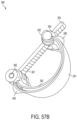
- FIGS. 58 A- 58 D show several views of a valve having two elongated support members, a connecting member, and a screw-type actuator in accordance with another embodiment of the present disclosure
- FIGS. 59 A- 59 C show several views of a body of a valve in accordance with an embodiment of the present disclosure
- FIGS. 59 D- 59 G show several views of a knob for use with the body shown in FIGS. 59 A- 59 C in accordance with an embodiment of the present disclosure
- FIG. 59 H shows the assembled valve that includes the body shown in FIGS. 59 A- 59 C coupled to the knob of FIGS. 59 D- 59 G in accordance with an embodiment of the present disclosure
- FIG. 60 shows a valve having a guiding protrusion in accordance with an embodiment of the present disclosure
- FIG. 61 shows a motor and a valve-securing structure for coupling to the valve of FIG. 60 in accordance with an embodiment of the present disclosure
- FIG. 62 shows the valve of FIG. 60 secured to the motor and the valve-securing structure of FIG. 61 in accordance with an embodiment of the present disclosure
- FIG. 63 shows another motor and valve-securing structure for coupling to the valve of FIG. 60 in accordance with an embodiment of the present disclosure
- FIG. 64 A shows a valve having a collar and several fingers for regulating fluid flow through a fluid line in accordance with an embodiment of the present disclosure
- FIG. 64 B shows a cross-sectional view of the valve of FIG. 64 A in accordance with an embodiment of the present disclosure
- FIG. 65 shows a cross-sectional view of a valve having two curved surfaces for positioning a fluid tube therebetween to regulate fluid flow through the fluid tube in accordance with an embodiment of the present disclosure
- FIGS. 66 A- 66 G show several views of a valve having a knob to move a connecting member which is locked into position after movement of the knob in accordance with an embodiment of the present disclosure
- FIG. 67 shows a graphic that illustrates actuation vs. flow rates for a valve in accordance with an embodiment of the present disclosure
- FIG. 68 A shows a flow meter that uses binary optics in accordance with an embodiment of the present disclosure
- FIG. 68 B shows the circuit for use with FIG. 68 A in accordance with an embodiment of the present disclosure
- FIGS. 69 A- 69 I show several views of a safety valve that may be used with a flow meter in accordance with an embodiment of the present disclosure
- FIG. 70 shows a flow chart diagram illustrating a method of estimating drop growth and/or flow within a drip chamber in accordance with an embodiment of the present disclosure
- FIGS. 71 A- 71 E show images taken by a flow meter with a template overlaid therein to illustrate the method of FIG. 70 in accordance with an embodiment of the present disclosure
- FIG. 72 shows a modulateable backlight assembly in accordance with an embodiment of the present disclosure
- FIGS. 73 A- 73 C show several views of a tube-restoring apparatus in accordance with an embodiment of the present disclosure
- FIG. 74 shows a system for regulating fluid flow using a valve having two flexible strips in accordance with an embodiment of the present disclosure
- FIG. 75 shows the valve of FIG. 74 in accordance with an embodiment of the present disclosure
- FIG. 76 A shows a valve that utilizes a fluid-based bladder in accordance with an embodiment of the present disclosure
- FIG. 76 B shows a cross-sectional view of the assembled valve of FIG. 76 A with two elastomeric fillers in accordance with an embodiment of the present disclosure
- FIG. 77 shows a system for regulating fluid flow using a valve having two flexible strips actuateable by a linear actuator in accordance with an embodiment of the present disclosure
- FIG. 78 shows the system of FIG. 77 with the valve actuated in accordance with an embodiment of the present disclosure
- FIG. 79 shows a close-up view of the valve of FIGS. 77 - 78 in accordance with an embodiment of the present disclosure
- FIG. 80 shows a close-up view of the valve as actuated in FIG. 78 in accordance with an embodiment of the present disclosure
- FIG. 81 shows several images for use to illustrate a method of estimating drop growth and/or fluid flow illustrated in FIGS. 82 A- 82 B in accordance with an embodiment of the present disclosure.
- FIGS. 82 A- 82 B show a flow chart diagram illustrating a method of estimating drop growth and/or fluid flow in accordance with an embodiment of the present disclosure
- FIG. 83 shows a flow chart diagram of a method for reducing noise from condensation in accordance with an embodiment of the present disclosure
- FIG. 84 shows another valve for use with a flow meter in accordance with an embodiment of the present disclosure
- FIG. 85 A shows a perspective view of another valve in an open position in accordance with an embodiment of the present disclosure
- FIG. 85 B shows a perspective view of the valve of FIG. 85 A in a closed position in accordance with an embodiment of the present disclosure
- FIG. 85 C shown a view of the valve of FIG. 85 A with the valve housing and plunger guide removed in accordance with an embodiment of the present disclosure
- FIG. 86 shows a cross-sectional view of the valve housing of FIGS. 85 A- 85 C and filler when in a closed position in accordance with an embodiment of the present disclosure
- FIG. 87 A show a front view of an apparatus with the door closed, the apparatus is used to control fluid flow through a drip chamber connected to a tube in accordance with an embodiment of the present disclosure
- FIG. 87 B shows a perspective view of the apparatus of FIG. 87 A with the door open, highlighting the valve in accordance with an embodiment of the present disclosure
- FIG. 87 C shows a perspective view of the apparatus of FIG. 87 A with the door open, highlighting the safety cutoff mechanism in accordance with an embodiment of the present disclosure
- FIG. 87 D shows a bottom view of the apparatus of FIG. 87 A in accordance with an embodiment of the present disclosure
- FIG. 88 A shows a perspective view of another apparatus used to control fluid flow through a drip chamber connected to a tube, wherein the apparatus has the door open, in accordance with an embodiment of the present disclosure
- FIG. 88 B shows a perspective view of only the valve from FIG. 88 A in accordance with an embodiment of the present disclosure
- FIG. 88 C shows the inner workings of the valve from FIG. 88 B in accordance with an embodiment of the present disclosure
- FIG. 88 D shows a simplified diagram illustrate the operation of the valve cutoff mechanism in a door closed position in accordance with an embodiment of the present disclosure
- FIG. 88 E shows a simplified diagram to illustrate the valve cutoff mechanism in the door open position in accordance with an embodiment of the present disclosure
- FIGS. 89 A- 89 B show a flow chart diagram of a method for controlling fluid flow through a drip chamber in accordance with an embodiment of the present disclosure
- FIG. 90 shows a diagram of a system for controlling fluid flow through a drip chamber in accordance with an embodiment of the present disclosure
- FIG. 91 shows an apparatus configured to control fluid flow through a drip chamber connected to a tube and communicate with an RFID interrogator in accordance with an embodiment of the present disclosure
- FIG. 92 shows an obstructed drip chamber that may render difficult the obtainment of an accurate image of the drip chamber by an image sensor in accordance with an embodiment of the present disclosure
- FIG. 93 shows a flow chart diagram of a method for obtaining an image of a drip chamber in accordance with an embodiment of the present disclosure
- FIG. 94 shows a graphical representation of drops, as seen by an image sensor, as each drop grows within a drip chamber and subsequently falls in accordance with an embodiment of the present disclosure
- FIG. 95 shows a graphical representation of a system to convey the status of a device in accordance with an embodiment of the present disclosure
- FIGS. 96 A- 96 X show several views of an apparatus to control fluid flow in accordance with an embodiment of the present disclosure
- FIGS. 97 A- 97 AC show several views of an apparatus to control fluid flow in accordance with an embodiment of the present disclosure
- FIG. 98 shows a top perspective view of a snap-fit drip chamber that may be used by the apparatus of FIGS. 97 A- 97 G in accordance with an embodiment of the present disclosure
- FIG. 99 shows a top view of the drip chamber of FIG. 98 in accordance with an embodiment of the present disclosure
- FIG. 100 shows a top sectional view of the drip chamber of FIG. 99 being inserted into the apparatus of FIGS. 97 A- 97 G in accordance with an embodiment of the present disclosure
- FIG. 101 shows a top sectional view of the drip chamber of FIG. 99 secured within the apparatus of FIGS. 97 A- 97 G in accordance with an embodiment of the present disclosure
- FIG. 102 shows a close-up view of the top cap of the drip chamber of FIG. 98 being inserted into an opening of the apparatus of FIGS. 97 A- 97 G in accordance with an embodiment of the present disclosure
- FIG. 103 shows a cross-sectional view of the apparatus of FIGS. 97 A- 97 G with the top cap of the drip chamber being secured therein accordance with an embodiment of the present disclosure
- FIGS. 104 - 105 show a cross-sectional view of the apparatus of FIGS. 97 A- 97 G with the top cap of the drip chamber to illustrate release of the drip chamber from the apparatus in accordance with an embodiment of the present disclosure
- FIG. 106 shows an embodiment of the drip chamber that uses mechanical resonance for drop detection in accordance with an embodiment of the present disclosure
- FIG. 107 shows an embodiment of the drip chamber that uses an optical light source and cantilever beam for drop detection in accordance with an embodiment of the present disclosure
- FIG. 108 A shows a drip chamber with an inner sleeve having parallel wires as an anti-pinch member in accordance with an embodiment of the present disclosure
- FIG. 108 B shows a cross-sectional view of the anti-pinch member of FIG. 108 A in accordance with an embodiment of the present disclosure
- FIG. 109 A shows a drip chamber with an outer sleeve having parallel wires as an anti-pinch member in accordance with an embodiment of the present disclosure
- FIG. 109 B shows a cross-sectional view of the anti-pinch member of FIG. 109 A in accordance with an embodiment of the present disclosure
- FIG. 110 A shows a drip chamber with an outer sleeve having a spiral wire as an anti-pinch member in accordance with an embodiment of the present disclosure
- FIG. 110 B shows a cross-sectional view of the anti-pinch member of FIG. 110 A in accordance with an embodiment of the present disclosure
- FIG. 111 A shows a drip chamber with an inner sleeve having a spiral wire as an anti-pinch member in accordance with an embodiment of the present disclosure
- FIG. 111 B shows a cross-sectional view of the anti-pinch member of FIG. 111 A in accordance with an embodiment of the present disclosure
- FIG. 112 shows a drip chamber with an section of tubing being an anti-pinch member in accordance with an embodiment of the present disclosure
- FIGS. 113 - 116 show several cross-sectional views of several embodiments of the section of tubing being an anti-pinch member of FIG. 112 in accordance with several embodiments of the present disclosure
- FIGS. 117 - 120 show several views of a snap-fit drip chamber in accordance with an embodiment of the present disclosure
- FIGS. 121 - 122 show the snap-fit drip chamber of FIGS. 117 - 120 secured within a flow meter in accordance with an embodiment of the present disclosure
- FIG. 123 shows a drip chamber having a fiducial for an image sensor to determine the location of the drip chamber in accordance with an embodiment of the present disclosure
- FIG. 124 shows a close-up view of the opening of the drip chamber of FIG. 123 in accordance with an embodiment of the present disclosure
- FIG. 125 shows a drip chamber having wings each of which includes a fiducial in accordance with an embodiment of the present disclosure
- FIGS. 126 - 127 show a drip chamber having lighting elements configured to internally light the chamber walls of the drip chamber in accordance with an embodiment of the present disclosure
- FIG. 128 shows a drip chamber with a solid stripe in accordance with an embodiment of the present disclosure
- FIG. 129 shows a drip chamber with a wing having a 2-D barcode embedded thereon in accordance with an embodiment of the present disclosure
- FIGS. 130 - 131 show a drip chamber that is keyed and includes a background pattern that is illuminated via light shined in through an edge of the background pattern in accordance with an embodiment of the present disclosure
- FIG. 132 shows a drip chamber having a barbed spike in accordance with an embodiment of the present disclosure
- FIG. 133 shows a drip chamber having a cylindrically-shaped chamber with lighting elements to illuminate a background pattern in accordance with an embodiment of the present disclosure
- FIG. 134 shows a drip chamber having a rectangular-shaped chamber with lighting elements to illuminate a background pattern in accordance with an embodiment of the present disclosure
- FIGS. 135 A- 135 C show a top cap with a pumping mechanism in accordance with an embodiment of the present disclosure
- FIG. 136 shows a drip chamber having a plurality of lighting elements in accordance with an embodiment of the present disclosure
- FIG. 137 shows a drip chamber having a plurality of internal ridges to facilitate liquid flow of condensation on the internal wall of the drip chamber in accordance with an embodiment of the present disclosure
- FIG. 138 shows a flow meter coupled to a bag via a spring in accordance with an embodiment of the present disclosure
- FIG. 139 shows a cross-section section of a drip chamber in accordance with an embodiment of the present disclosure
- FIG. 140 shows a flow meter coupled to a drip chamber in accordance with an embodiment of the present disclosure
- FIGS. 141 A- 141 B show a drip chamber having a fiducial on a wing and within the drip chamber in accordance with an embodiment of the present disclosure
- FIG. 142 A shows a drip chamber with a bar code in accordance with an embodiment of the present disclosure
- FIG. 142 B shows several exemplary barcodes that may be used on the drip chamber in accordance with an embodiment of the present disclosure
- FIG. 143 shows a drip chamber with an RFID tag in accordance with an embodiment of the present disclosure
- FIG. 144 shows a schematic drawing of a shuttle pump using duckbill check valves in accordance with an embodiment of the present disclosure
- FIG. 145 shows a schematic drawing of a shuttle pump in accordance with an embodiment of the present disclosure
- FIG. 146 shows a schematic drawing of a shuttle pump using an eccentric cam coupled to a motor in accordance with an embodiment of the present disclosure.
- FIG. 147 shows a drip chamber using a piston pump and check valves in accordance with an embodiment of the present disclosure.
- FIG. 1 shows a block diagram of a system 1 for regulating fluid flow in accordance with an embodiment of the present disclosure.
- system 1 may regulate, monitor, and/or control the flow of fluid into a patient 3 .
- the system 1 includes a fluid reservoir 2 for infusing fluid contained therein into the patient 3 .
- the fluid reservoir 2 is gravity fed into a drip chamber 4 via a fluid tube 5 .
- the fluid reservoir 2 , the drip chamber 4 , and the patient 3 may be considered as part of the system 1 or may be considered as separate or optional work pieces for the system 1 (e.g., any fluid reservoir 2 and drip chamber 4 may be used to treat any patient 3 ).
- a flow meter 7 monitors the drip chamber 4 to estimate a flow rate of liquid flowing through the drip chamber 4 .
- the fluid from the drip chamber 4 is gravity fed into a valve 6 .
- the valve 6 regulates (i.e., varies) the flow of fluid from the fluid reservoir 2 to the patient 3 by regulating fluid flow from the drip chamber 4 to the patient 3 .
- the valve 6 may be any valve as described herein, including a valve having two curved-shaped members, a valve having two flexible sheets, a valve that pinches (or uniformly compresses) on the tube over a significant length of the tube, or the like.
- the valve 6 may be an inverse-Bourdon-tube valve that works in an opposite way of a Bourdon tube in that a deformation of the fluid path causes changes in fluid flow rather than fluid flow causing deformation of the fluid path.
- the system 1 optionally includes an infusion pump 414 (e.g., a peristaltic pump, a finger pump, a linear peristaltic pump, a rotary peristaltic pump, a cassette-based pump, a membrane pump, other pump, etc.) coupled to the fluid tube 5 .
- the outlined box designated as 414 represents the optional nature of the infusion pump 414 , e.g., the infusion pump may not be used in some embodiments.
- the infusion pump 414 may use the flow meter 7 as feedback to control the flow of fluid through the fluid tube 5 .
- the infusion pump 414 may be in wireless communication with the flow meter 7 to receive the flow rate therefrom.
- the infusion pump 414 may use a feedback control algorithm (e.g., the control component 14 of FIG. 1 ) to adjust the flow of fluid, such as a proportional-integral-derivative (“PID”), bang-bang, neural network, and/or fuzzy logic control system.
- PID proportional-integral-derivative
- the valve 6 is optional.
- the valve 6 may or may not be used, and/or is optional.
- the infusion pump 414 may adjust the rotation of a cam and/or a motor in accordance with measurements from the flow meter 7 , such as flow rate, volume infused, total volume infused, etc.
- the infusion pump 414 may stop fluid flow (e.g., by stopping the pumping action) when the flow meter 7 communicates to the infusion pump 414 that a free flow condition exists.
- the monitoring client 8 controls the operation of the infusion pump 414 (e.g., via a wireless connection) and receives feedback from the flow meter 7 .
- the fluid reservoir 2 is pressurized to facilitate the flow of fluid from the fluid reservoir 2 into the patient 3 , e.g., in the case where the fluid reservoir 2 (e.g., an IV bag) is below the patient 3 ;
- the pressurization provides sufficient mechanical energy to cause the fluid to flow into the patient 3 .
- a variety of pressure sources, such as physical pressure, mechanical pressure, and pneumatic pressure may be applied to the inside or outside of the fluid reservoir 2 .
- the pressurization may be provided by a rubber band wrapped around an IV bag.
- the flow meter 7 and the valve 6 may form a closed-loop system to regulate fluid flow to the patient 3 .
- the flow meter 7 may receive a target flow rate from a monitoring client 8 by communication using transceivers 9 , 10 . That is, the transceivers 9 , 10 may be used for communication between the flow meter 7 and the monitoring client 8 .
- the transceivers 9 , 10 may communicate between each other using a modulated signal to encode various types of information such as digital data or an analog signal. Some modulation techniques used may include using carrier frequency with FM modulation, using AM modulation, using digital modulation, using analog modulation, or the like.
- the flow meter 7 estimates the flow rate through the drip chamber 4 and adjusts the valve 6 to achieve the target flow rate received from the monitoring client 8 .
- the valve 6 may be controlled by the flow meter 7 directly from communication lines coupled to an actuator of the valve 6 or via a wireless link from the flow meter 7 to onboard circuitry of the valve 6 .
- the onboard electronics of the valve 6 may be used to control actuation of the valve 6 via an actuator coupled thereto.
- This closed-loop embodiment of the flow meter 7 and the valve 6 may utilize any control algorithm including a PID control algorithm, a neural network control algorithm, a fuzzy-logic control algorithm, the like, or some combination thereof.
- the flow meter 7 is coupled to a support member 17 that is coupled to the drip chamber 4 via a coupler 16 .
- the support member 17 also supports a backlight 18 .
- the backlight 18 includes an array of LEDs 20 that provides illumination to the flow meter 7 .
- the backlight 18 includes a background pattern 19 .
- the backlight 18 does not include the background pattern 19 .
- the background pattern 19 is present in only the lower portion of the backlight 18 and there is no background pattern 19 on the top (e.g., away from the ground) of the backlight 18 .
- the flow meter 7 includes an image sensor 11 , a free flow detector component 12 , a flow rate estimator component 13 , a control component 14 , an exposure component 29 , a processor 15 , and a transceiver 9 .
- the flow meter 7 may be battery operated, may be powered by an AC outlet, may include supercapacitors, and may include on-board, power-supply circuitry (not explicitly shown).
- the image sensor 11 may be a CCD sensor, a CMOS sensor, or other image sensor.
- the image sensor 11 captures images of the drip chamber 4 and communicates image data corresponding to the captured images to the processor 15 .
- the processor 15 is also coupled to the free flow detector component 12 , the flow rate estimator component 13 , the control component 14 , and the exposure component 29 .
- the free flow detector component 12 , the flow rate estimator component 13 , the control component 14 , and the exposure component 29 may be implemented as processor-executable instructions that are executable by the processor 15 and may be stored in memory, such as a non-transitory, processor-readable memory, ROM, RAM, EEPROM, a harddisk, a harddrive, a flashdrive, and the like.
- the processor 15 can execute the instructions of the free flow detector component 12 to determine if a free flow condition exists within the drip chamber 4 by analyzing the image data from the image sensor 11 .
- Various embodiments of the free flow detector component 12 for detecting a free flow condition are described below.
- the processor 15 can make a function call to the control component 14 to send a signal to the valve 6 to completely stop fluid flow to the patient 3 .
- the flow meter 7 may instruct the valve 6 to stop fluid flow, may instruct the monitoring client 8 to stop fluid flow (which may communicate with the valve 6 or the pump 414 ), and/or may instruct the pump 414 to stop pumping or occlude fluid flow using an internal safety occluder.
- the flow rate estimator component 13 estimates the flow rate of fluid flowing through the drip chamber 4 using the image data from the image sensor 11 .
- the processor 15 communicates the estimated flow rate to the control component 14 (e.g., via a function call). Various embodiments of estimating the flow rate are described below. If the flow rate estimator component 13 determines that the flow rate is greater than a predetermined threshold or is outside a predetermined range, the flow meter 7 may instruct the valve 6 to stop fluid flow (which may communicate with the valve 6 or the pump 414 ), may instruct the monitoring client 8 to stop fluid flow (which may communicate with the valve 6 or the pump 414 ), and/or may instruct the pump 414 to stop pumping or occlude fluid flow using an internal safety occluder.
- the processor 15 controls the array of LEDs 20 to provide sufficient light for the image sensor 11 .
- the exposure component 29 may be used by the processor 15 or in conjunction therewith to control the array of LEDs 20 such that the image sensor 11 captures image data sufficient for use by the free flow detector component 12 and the flow rate estimator component 13 .
- the processor 15 may implement an exposure algorithm stored by the exposure component 29 (see FIG. 2 ) to control the lighting conditions and/or the exposure of the image sensor 11 when generating the image data.
- the exposure component 29 may be implemented as a circuit, an integrated circuit, a CPLD, a PAL, a PLD, a hardware-description-language-based implementation, and/or a software system.
- the control component 14 calculates adjustments to make to the valve 6 in accordance with the estimated flow rate from the flow rate estimator component 13 .
- the control component 14 may implement a PID control algorithm to adjust the valve 6 to achieve the target flow rate.
- the monitoring client 8 monitors operation of the system 1 . For example, when a free flow condition is detected by the free flow detector component 12 , the monitoring client 8 may wirelessly communicate a signal to the valve 6 to interrupt fluid flow to the patient 3 .
- the flow meter 7 may additionally include various input/output devices to facilitate patient safety, such as various scanners, and may utilize the transceiver 9 to communicate with electronic medical records, drug error reduction systems, and/or facility services, such as inventory control systems.
- the flow meter 7 has a scanner, such as an RFID interrogator that interrogates an RFID tag attached to the fluid reservoir 2 or a barcode scanner that scans a barcode of the fluid reservoir 2 .
- the scanner may be used to determine whether the correct fluid is within the fluid reservoir 2 , it is the correct fluid reservoir 2 , the treatment programmed into the flow meter 7 corresponds to the fluid within the fluid reservoir 2 and/or the fluid reservoir 2 and flow meter 7 are correct for the particular patient (e.g., as determined from a patient's barcode, a patient's RFID tag, or other patient identification).
- the flow meter 7 may scan the RFID tag of the fluid reservoir 2 to determine if a serial number or fluid type encoded within the RFID tag is the same as indicated by the programmed treatment stored within the flow meter 7 . Additionally or alternatively, the flow meter 7 may interrogate the RFID tag of the fluid reservoir 2 for a serial number and the RFID tag of the patient 3 for a patient serial number, and also interrogate the electronic medical records using the transceiver 9 to determine if the serial number of the fluid reservoir 2 within the RFID tag attached to the fluid reservoir 2 matches the patient's serial number within the RFID tag attached to the patient 3 as indicated by the electronic medical records.
- the monitoring client 8 may scan the RFID tag of the fluid reservoir 2 and the RFID tag of the patient 3 to determine that it is the correct fluid within the fluid reservoir 2 , it is the correct fluid reservoir 2 , the treatment programmed into the flow meter 7 corresponds to the fluid within the fluid reservoir 2 , and/or the fluid reservoir 2 is correct for the particular patient (e.g., as determined from a patient's barcode, RFID tag, electronic medical records, or other patient identification or information). Additionally or alternatively, the monitoring client 8 or the flow meter 7 may interrogate the electronic medical records database and/or the pharmacy to verify the prescription or to download the prescription, e.g., using the serial number of the barcode on the fluid reservoir 2 or the RFID tag attached to the fluid reservoir 2 .
- FIG. 2 shows a flow chart diagram of a method 21 for exposing an image sensor, e.g., the image sensor 11 of FIG. 1 , in accordance with an embodiment of the present disclosure.
- the method 21 includes acts 22 , 23 , 24 , and 25 .
- Method 21 may be implemented by the processor 15 of FIG. 1 (e.g., as the exposure component 29 ) and may be implemented as a processor-implemented method, as a set of instructions configured for execution by one or more processors, in hardware, in software, the like, or some combination thereof.
- Act 22 selects a region of interest.
- the image sensor 11 includes a field of view that includes the drip chamber 4 .
- the drip chamber 4 may not occupy the entire field of view of the image sensor 11 .
- Act 22 selects only the pixels of the image sensor 11 that show, for example, the drip chamber 4 .
- Act 23 determines if a pixel is within the region of interest 23 . If the pixel of act 23 is a pixel that images, for example, the drip chamber 4 , then act 23 determines that it is within the region of interest. Likewise, in this example, if the pixel of act 23 is a pixel that does not image the drip chamber 4 , act 23 determines that the pixel is not within the region of interest.
- Act 24 activates a backlight, e.g., the backlight 18 of FIG. 1 , if the pixel is within the region of interest. Pixels of an image sensor may be exposed during different times. Thus, the backlight 18 may be activated only when pixels within the region of interest are being exposed. For example, some image sensors include vertical and horizontal sync signals. The backlight may be synchronized with these signals to turn on when a pixel of interest is being exposed.
- a subset of LEDs of the backlight may be turned on.
- the subset may be a sufficient subset to sufficiently illuminate the pixel being exposed if the pixel is within the region of interest.
- Act 25 exposes the pixel. If in act 23 it was determined that the pixel is within the region of interest, the pixel will be exposed with at least a portion of the backlight turned on in act 25 . Additionally, if in act 23 it was determined that the pixel is not within the region of interest, the pixel will be exposed without at least a portion of the backlight turned on in act 25 .
- FIG. 3 shows a timing diagram 29 illustrating an embodiment of the method of FIG. 2 in accordance with an embodiment of the present disclosure.
- the timing diagram 29 includes traces 26 , 27 , and 28 .
- Trace 26 is a vertical sync signal from an image sensor and trace 27 is a horizontal sync signal from the image sensor (e.g., image sensor 11 of FIG. 1 ).
- a circuit or software routine e.g., the exposure component 29 found in the flow meter 7 of FIG. 1 ) may use the sync traces 26 , 27 to generate a backlight-enable signal 28 that is used to activate a backlight or a subset thereof.
- FIGS. 4 A- 4 B show illustrations of image data of a flow meter 7 illustrating an embodiment of the method of FIG. 2 in accordance with the timing diagram of FIG. 3 in accordance with an embodiment of the present disclosure.
- FIG. 4 A illustrates the image data taken by a flow meter, such as the flow meter 7 of FIG. 1 , without the use of the exposure algorithm illustrated in FIGS. 2 and 3 ;
- FIG. 4 B illustrates the image data taken by the flow meter with the use of the exposure algorithm illustrated in FIGS. 2 and 3 .
- Less power is needed to provide illumination during the capture of the image of FIG. 4 B than to provide illumination for the capture of the image of FIG. 4 A because of less use of the backlight.
- FIG. 5 shows a diagram of a flow meter 67 and a valve 71 that are integrated together for coupling to a drip chamber 409 and an IV bag 69 in accordance with an embodiment of the present disclosure.
- the flow meter 67 includes an optical drip counter 68 that receives fluid from the IV bag 69 .
- the optical drip counter 68 may be an image sensor, a pair of image sensors, a capacitive drip counter, and/or the like.
- the flow meter 67 is coupled to a tube 70 coupled to a roller clamp 71 that is controlled by a motor 72 .
- the motor 72 is coupled to a lead screw mechanism 73 to control a roller clamp 71 via interaction with interacting members 74 .
- the motor 72 may be a servo motor and may be used to adjust the flow rate through the tube 70 . That is, the flow meter 67 may also function as a flow meter and regulator. For example, a processor 75 within the flow meter 67 may adjust the motor 72 such that a desired flow rate is achieved as measured by the optical drip counter 68 .
- the processor 75 may implement a control algorithm using the optical drip counter 68 as feedback, e.g., a PID control loop with the output supplied to the motor 72 and the feedback received from the optical drip counter 68 .
- the motor 72 , the lead screw mechanism 73 , and the roller clamp 71 may be replaced and/or supplemented by an actuator that squeezes the tube 70 (e.g., using a cam mechanism or linkage driven by a motor) or they may be replaced by any sufficient roller, screw, or slider driven by a motor.
- the roller clamp 71 may be replaced by any valve as described herein, including a valve having two C-shaped members, a valve having two curve-shaped support members, a valve having two flexible sheets, a valve that pinches on the tube over a significant length of the tube, or the like.
- the flow meter 67 may also optionally include a display.
- the display may be used to set the target flow rate, display the current flow rate, and/or provide a button, e.g., a touch screen button to stop the flow rate.
- FIG. 6 is a block diagram of an imaging system 78 of a flow meter for imaging a drip chamber in accordance with an embodiment of the present disclosure.
- the imaging system 78 as shown in FIG. 6 may be used within any flow meter described herein, including the flow meter 7 of FIG. 1 and/or the flow meter 67 of FIG. 5 .
- the imaging system 78 of FIG. 6 includes an image sensor 63 , a uniform backlight 79 to shine light at least partially through the drip chamber 59 , and an infrared (“IR”) filter 80 that receives the light from the uniform backlight 79 .
- IR infrared
- System 78 also includes a processor 90 that may be operatively coupled to the image sensor 63 and/or the uniform backlight 79 .
- the processor 90 implements an algorithm to determine when a free flow condition exists and/or to estimate a flow rate (e.g., using the free flow detector component 12 or the flow rate estimator component 13 of FIG. 1 ).
- the processor 90 may be in operative communication with a processor-readable memory 91 (e.g., a non-transitory, processor-readable memory) to receive one or more instructions to implement the algorithm to determine if a free flow condition exists and/or to estimate the flow rate.
- the one or more instructions from the processor-readable memory 91 are configured for execution by the processor 90 .
- the uniform backlight 79 may be an array of light-emitting diodes (“LEDs”) having the same or different colors, a light bulb, a window to receive ambient light, an incandescent light, and the like. In some embodiments, the uniform backlight 79 may include one or more point-source lights.
- LEDs light-emitting diodes
- the uniform backlight 79 may include one or more point-source lights.
- the processor 90 may modulate the uniform backlight 79 in accordance with the image sensor 63 .
- the processor 90 may activate the uniform backlight 79 for a predetermined amount of time and signal the image sensor 63 to capture at least one image, and thereafter signal the uniform backlight 79 to turn off.
- the one or more images from the image sensor 63 may be processed by the processor 90 to estimate the flow rate and/or detect free flow conditions.
- the system 78 monitors the size of the drops being formed within the drip chamber 59 , and counts the number of drops that flow through the drip chamber 59 within a predetermined amount of time; the processor 90 may average the periodic flow from the individual drops over a period of time to estimate the flow rate. For example, if X drops each having a volume Y flow through the drip chamber in a time Z, the flow rate may be calculated as (X*Y)/Z.
- the system 78 may determine when the IV fluid is streaming through the drip chamber 59 (i.e., during a free flow condition).
- the uniform backlight 79 shines light through the drip chamber 59 to provide sufficient illumination for the image sensor 63 to image the drip chamber 59 .
- the image sensor 63 can capture one or more images of the drip chamber 59 .
- orientations and configurations of the system 78 may be used to account for the orientation and output characteristics of the uniform backlight 79 , the sensitivity and orientation of the image sensor 63 , and the ambient light conditions.
- the processor 90 implements an algorithm that utilizes a uniformity of the images collected by the image sensor 63 .
- the uniformity may be facilitated by the uniform backlight 79 .
- consistent uniform images may be captured by the image sensor 63 when a uniform backlight 79 is utilized.
- Ambient lighting may cause inconsistencies in the images received from the image sensor 63 ; for example, direct solar illumination provides inconsistent lighting because the sun may be intermittently obscured by clouds and the sun's brightness and angle of illumination depend upon the time of the day. Therefore, in some embodiments of the present disclosure, an IR filter 80 is optionally used to filter out some of the ambient light to mitigate variations in the images captured by the image sensor 63 .
- the IR filter 80 may be a narrow-band infrared light filter placed in front of the image sensor 63 ; and the uniform backlight 79 may emit light that is about the same wavelength as the center frequency of the passband of the filter 80 .
- the IR filter 80 and the uniform backlight 79 may have a center frequency of about 850 nanometers.
- the imaging system 78 may be surrounded by a visually translucent, but IR-blocking, shell. In alternative embodiments, other optical frequencies, bandwidths, center frequencies, or filter types may be utilized in the system 78 .
- the processor 90 may use a template to perform a template match of the pool of water within the drip chamber 59 . Any preprocessing may be performed prior to the template match operation. Additionally, if the camera 63 is disposed higher than a preferred position, a mirror may be used so that the camera's 63 view is of a preferable view of the drip chamber 59 . The position of the peak template match may be correlated to the pool's position and hence the pool's volume.
- the apparatus may trigger a safety valve (described below) because water is leaving the pool and is draining toward the patient at an unsafe rate.
- the backlight 79 may be on or off, depending on the embodiment.
- the oscillations of the top of the pool may be monitored to determine the resonance frequency of the water.
- the resonance of the top of the pool as the drops hit the pool may be correlated with the volume of the pool.
- the sudden change of the pool may be correlated with a drop hitting the pool such that the processor 90 can count the number of drops per unit time and estimate the fluid flow therethrough.
- autofocus may be used to find the line of water. That is, a focal line may be focused to ensure the entire image is focused.
- the processor 90 may be coupled to a wire etched onto a PCB board making it a software radio. This allows the processor 90 to communicate information to another device capable of operating at the sufficient frequencies.
- FIG. 7 is a graphic illustration of an image 81 captured by the image sensor 63 of the system 78 of FIG. 6 in accordance with an embodiment of the present disclosure.
- the image 81 is an image of a drip chamber 59 having condensation 82 and a stream 83 caused by a free flow condition therein.
- Edge detection may be used to determine the position of the stream 83 and/or the condensation 82 , in some embodiments. Additionally or alternatively, a background image or pattern may be used.
- FIG. 8 is a block diagram of an imaging system 84 of a flow meter for imaging a drip chamber in accordance with an embodiment of the present disclosure.
- the imaging system 84 may be used with any flow meter disclosed herein, including the flow meter 7 of FIG. 1 and the flow meter 67 of FIG. 5 .
- System 84 includes an array of lines 85 that are opaque behind the drip chamber 59 .
- System 84 uses the array of lines 85 to detect a free flow condition.
- the free flow detection algorithm e.g., the free flow detector component 12 of FIG. 1
- the lines 85 are only present on a fraction of the image (e.g., the background pattern only occupies a fraction of the backlight 18 or the binary optics only causes the pattern to appear in a fraction of the image, such as the lower or upper half).
- a lower fraction of the image may include a background pattern of stripes.
- FIG. 9 a graphic illustration of an image 86 is shown as captured by the image sensor 63 of FIG. 8 when a free flow condition exists in the drip chamber 59 in accordance with an embodiment of the present disclosure.
- the image 86 illustrates the condition in which the drip chamber 59 experiences a free flow condition and illustrates the effect that the stream of fluid 87 acts as a positive cylindrical lens. That is, as shown in FIG. 9 , the array of lines 85 as captured in an image by the image sensor 63 are shown as a reversed line pattern 88 from the array of lines 85 as compared to a non-free flow condition. The appearance of the reversed line pattern 88 is caused by changes to the light when the light passes through the stream of fluid 87 as the light approaches the image sensor 63 .
- illumination by light having an optical wavelength of about 850 nanometers may be used to create the image 86 .
- Some materials may be opaque in the visible spectrum and transparent in the near IR spectrum at about 850 nanometers and therefore may be used to create the array of lines 85 .
- the array of lines 85 may be created using various rapid-prototyping plastics.
- the array of lines 85 may be created using a rapid-prototype structure printed with an infrared-opaque ink or coated with a metal for making the array of lines 85 .
- another method of creating the array of lines 85 is to create a circuit board with the lines laid down in copper.
- the array of lines 85 is created by laying a piece of ribbon cable on the uniform backlight 79 ; the wires in the ribbon cable are opaque to the infrared spectrum, but the insulation is transparent such that the spacing of the wires may form the line for use during imaging by the image sensor 63 (see FIG. 8 ).
- a piece of thin EDMed metal may be utilized. Metal is opaque to light and the spaces between the metal material deposits may be very finely controlled during manufacture to allow the IR light to pass through the spaces.
- the processor 90 implements an algorithm to determine when a free flow condition exists (e.g., using the free flow detector component 12 of FIG. 1 ).
- the processor 90 may be in operative communication with a processor-readable memory 91 (e.g., a non-transitory, processor-readable memory) to receive one or more instructions to implement the algorithm to determine if a free flow condition exists.
- the one or more instructions from the processor-readable memory 91 are configured for execution by the processor 90 .
- blood may be used by the system 84 .
- system 84 may determine when a free flow condition of blood exists when utilizing the image sensor 63 , the IR filter 80 , and the uniform backlight 79 configured, for example, for use using optical light having a wavelength of 850 nanometers or 780 nanometers, e.g., when using bovine blood.
- the blood may appear opaque compared to the images taken using water.
- the following algorithm implemented by the processor 90 and received from the processor-readable memory 91 may be used to determine when a free flow condition exists: (1) establish a background image 89 (see FIG. 10 ); and (2) subtract the background image 89 from the current image. Additionally processing may be performed on the resulting image.
- the background image 89 of FIG. 10 may be dynamically generated by the processor 90 .
- the dynamic background image may be used to account for changing conditions, e.g. condensation or splashes 82 on the surface of the drip chamber 59 (see FIG. 7 ).
- the background image has each pixel multiplied by 0.96 and the current image (e.g., the most recently captured image) has a respective pixel multiplied by 0.04, after which the two values are added together to create a new value for a new background image for that respective pixel; this process may be repeated for all of the pixels.
- the new background image at row, x, and column, y is the value of the previous background image at row, x, and column, y, multiplied by 0.96, which is added to the value of the pixel at row, x, and column, y of the new image multiplied by 0.04.
- the resulting subtraction should be almost completely back, i.e., low pixel magnitudes, thereby facilitating the algorithm to determine that the drip chamber 59 has no water flowing therethrough.
- FIG. 11 shows an image 92 from the image sensor 63 when there is a drop within the drip chamber 59 (see FIG. 8 ).
- FIG. 12 shows a background image 93 used by the system 84 .
- the system 84 of FIG. 8 has a few high contrast-spots where the image of the array of lines is warped by the lensing of the droplet as illustrated by an image 94 of FIG. 13 .
- Image 94 of FIG. 13 is generated by taking, for each respective pixel, the absolute value of the subtraction of the image 92 of FIG. 11 from image 93 of FIG.
- Each white pixel within the image 94 of FIG. 13 is a result of there being a difference for that pixel location between the images 92 and 93 that is greater than a predetermined threshold.
- the pixel at row x and column y of image 92 of FIG. 11 is subtracted from the pixel at row x and column y of image 93 of FIG. 12 , then the absolute value of the result of the subtraction is taken; and if the absolute value of the result is above a predetermined threshold (e.g., above a grayscale value of 128, for example), the pixel at the location of row x and column y of image 94 of FIG. 13 is white, otherwise the pixel at the location of row x and column y of image 94 of FIG. 13 is black.
- a predetermined threshold e.g., above a grayscale value of 128, for example
- the processor 90 of system 84 determines that drops are being formed within the drip chamber 59 and no free flow condition exists.
- the images of the drops may be utilized to determine the size of the drops to estimate a flow rate as described herein.
- FIG. 14 is a graphic representation of some of the image processing that may be performed using FIGS. 11 - 13 to determine if a free flow condition exists in accordance with an embodiment of the present disclosure. Referring to FIGS. 14 and 13 , all of the white pixels for each row are summed together, and are illustrated in FIG. 14 as results 183 . The y-axis represents the row number, and the x-axis represents the summed number of white pixels for each respective row.
- the number of white pixels for each row is summed together and is illustrated as results 183 , which are used to determine if or when a free flow condition exists.
- the processor 90 of system 84 determines that a free flow condition exists when a predetermined number of contiguous values of the summed rows of the results 183 exists above a threshold 184 .
- a range of a plurality of contiguous rows represented generally by 185 has a total value above the threshold 184 .
- a free flow condition is determined to exist by the processor 90 of FIG. 8 .
- the range of the plurality of contiguous summed rows 185 is below the predetermined number of contiguous summed rows (i.e., the range 185 is not wide enough) and therefore a free flow condition is determined to not exist.
- FIG. 15 shows an image 95 showing a stream as captured by the image sensor 63 of FIG. 8 when a free flow condition exists.
- FIG. 16 shows a background image 96 .
- FIG. 17 shows an image 97 formed by the absolute value of the difference between the image 96 of FIG. 16 and the image 95 from FIG. 15 when the absolute value is converted either to a white pixel (when the absolute value of the difference is above a threshold) or to a black pixel (when the absolute value of the difference is below the threshold).
- high-contrast spots caused by the reverse orientation of the lines in the stream that run from top to bottom are detectable by the processor 90 .
- the processor 90 of FIG. 8 can use the image 97 to determine if a free flow condition exists using the algorithm described above.
- results 186 are shown as having a contiguous range 187 of the results 186 that are above a threshold 188 . Because the contiguous range 187 of summed rows is greater than a predetermined threshold number of contiguous values above the threshold 188 , a free flow condition is determined to exist by the processor 90 (see FIG. 8 ). That is, the contiguous range of the results 186 above the threshold 188 is greater than a predetermined threshold range of contiguous values; therefore, the processor 90 determines that a free flow condition exists when using the results 186 of FIG. 18 .
- the intensity, the intensity squared, or other function may be used to produce the results 183 of FIG. 14 and/or the results 186 of FIG. 18 .
- one or more data smoothing functions may be used to smooth the results 183 and/or 186 , such as a spline function, a cubic spline function, a B-spline function, a Bezier spline function, a polynomial interpolation, a moving average, or other data smoothing function.
- an image of the image sensor 63 of FIG. 8 may be subtracted from a background image, e.g., the image 96 of FIG. 16 , to obtain intensity values. That is, a pixel of row x and column y of FIG. 15 may be subtracted from a pixel of row x and column y of the image 96 of FIG. 16 to create an intensity value at row x and column y; this may be repeated for all pixel locations to obtain all of the intensity values.
- the intensity values of each row may be summed together to obtain the results 183 and/or 186 (see FIGS.
- the processor 90 may determine that a free flow condition exists when the summed rows of the intensity values has a contiguous range of summed rows above a threshold.
- the intensity values are converted to absolute values of the intensity values, and the summed rows of the absolute values of the intensity values are used to determine if a contiguous range of summed rows of the absolute values is above a threshold range of contiguous values.
- the intensity may be squared and then the processor 90 may sum the squared intensity rows and determine if a contiguous range of summed rows of the intensity squared values exists beyond a threshold range of contiguous values to determine if a free flow condition exists.
- a predetermined range of contiguous values above a threshold (e.g., min and max ranges) of the summed rows of intensity values or intensity squared values may be used by the processor 90 to determine if a drop of liquid is within the image. For example, each row of the rows of the intensity values (or the intensity squared values) may be summed together and a range of the summed values may be above a threshold number; if the range of contiguous values is between a minimum range and a maximum range, the processor 90 may determine that the range of contiguous values above a predetermined threshold is from a drop within the field of view of the image sensor 63 (see FIG. 8 ).
- the summed rows of intensity values or intensity squared values may be normalized, e.g., normalized to have a value between 0 and 1.
- the following describes a smoothing function similar to the cubic spline (i.e., the cubic-spline-type function) that may be used on the summed rows, the summed rows of intensity values, or the summed rows of the intensity values squared prior to the determination by the processor 90 to determine if a free flow condition exits.
- the cubic-spline-type function may be used to identify blocks, as described infra, which may facilitate the processor's 90 identification of free flow conditions.
- the cubic-spline-type function is an analog to the cubic spline, but it smoothes a data set rather than faithfully mimics a given function.
- D i ⁇ i 2 6 ⁇ ( B i 3 ⁇ ( x ) - B i ⁇ ( x ) ) . ( 2 )
- Equation (1) and (2) guaranty continuity and curvature continuity.
- the only values which can be freely chosen are y i , y′′ 0 and y N ′′.
- Equation (4) can be rewritten as the set of Equations (5) as follows:
- Equation (8) is the minimum deviation between the data and the spline, i.e., Equation (8) is an error function.
- the y values are chosen to minimize the error as defined in Equation (8).
- the vector of predicted values can be written as illustrated in Equation (9) as follows:
- Equation (10) The elements of the matrix in brackets of Equation (9) depend upon the x-value corresponding to each data point (but this is a fixed matrix).
- the final equation can be determined using the pseudo-inverse.
- Equation (12) Equation (12) as follows:
- Equation (12) can be written as Equation (13) as follows:
- the cubic spline data may include “blocks” of data that includes values above a predetermined threshold.
- a pipe block is formed by the liquid flowing out of the tube into the drip chamber 59 and a pool block is formed as the liquid collects at the gravity end of the drip chamber 59 (see FIG. 8 ).
- the following algorithm may be applied to the cubic spline data: (1) determine the local maxima of the cubic spline data using the derivative information; (2) determine the block surrounding each local maxima by including all points where the cubic spline value is above a threshold value; (3) merge all blocks which intersect; (4) calculate information about the block of data including the center of mass (intensity), the second moment of the mass (intensity), the lower x-value of the block, the upper x-value of the block, the mean value of the original sum of intensity squared data in the block, the standard deviation of the original sum of intensity squared data in the block, and the mean intensity of a high-pass filtered image set in the block; and (5) interpret the collected data to obtain information about when drops occur and when the system is streaming.
- the mean intensity of a high-pass filtered image set in the block is used to determine if the block created by each contiguous range of spline data is a result of a high frequency artifact (e.g., a drop) or a low frequency artifact.
- a high frequency artifact e.g., a drop
- a low frequency artifact e.g., a low frequency artifact.
- This will act as a second background filter which tends to remove artifacts such as condensation from the image. That is, all previous images in an image memory buffer (e.g., 30 previous frames, for example) are used to determine if the data is a result of high frequency movement between frames. If the block is a result of low frequency changes, the block is removed, or if it is a result of high frequency changes, the block is kept for further analysis.
- a finite impulse response filter or an infinite impulse response filter may be used.
- Each block is plotted over its physical extent with the height equal to the mean value of the data within the block. If a block has a mean value of the high-pass filtered image less than the threshold, it is an indication that it has been around for several images and thus may be removed.
- Free flow conditions may be determined by the processor 90 (see FIG. 6 or 8 ) to exist using the blocks when the pipe block extends nearly to the pool block, the pipe block and the pool block merge together, and/or the summed range of widths of the pool and pipe blocks (or all blocks) is greater than a predetermined threshold, e.g., the total extent of the blocks exceeds 380 pixels in width.
- the processor 90 may detect a drop when the transition of the pipe block from a larger width to a shorter width occurs as a result of a drop formation in the tube and as the drop leaves the pipe (i.e., tube) opening of the drip chamber 59 .
- the processor 90 may detect this by looking at the ratio of the current pipe block width to the previous image's pipe block width, e.g., an image where the ratio is less than 0.9 as is also a local minima may be considered by the processor 90 to be an image formed immediately after a drop has formed.
- Various filtering algorithms may be used to detect condensation or other low frequency artifacts, such as: if a block has a low mean value in the high-pass filtered image, then it may be condensation. This artifact can be removed from consideration. Additionally or alternatively, long blocks (e.g., greater than a predetermined threshold) with a low high-pass mean value are possibly streams because stream images tend to remain unchanging; the processor 90 may determine that long blocks greater than a predetermined threshold corresponds to a streaming condition. Additionally or alternatively, an algorithm may be used on the current image to detect free flow conditions.
- the processor 90 may, in some specific embodiments, use the block data to count the drops to use the system 84 as a drop counter.
- the processor 90 may also use width changes in the pool block as a drop disturbs the water to determine if a bubble formed when the drop hits the pool. For example, the processor 90 may determine that blocks that form below the pool block are from bubbles that formed when the drop hit the water.
- the bubble may be filtered out by the processor 90 when determining if a predetermined value of total block ranges indicates that a free flow condition exists.
- the depth of field of the system 84 may have a narrow depth of field to make the system 84 less sensitive to condensation and droplets on the chamber walls.
- a near focus system may be used.
- a template 189 is used to determine if a free flow condition exists.
- the template 189 is used by the processor 90 of FIG. 8 to determine a pattern match score 190 when performing a template match algorithm on an image, e.g., the image 94 of FIG. 13 .
- the template 189 may be compared to the image 94 to determine if a portion or all of the image 94 closely matches the template 189 .
- the image 94 of FIG. 13 is a difference between a background image and an image captured by the image sensor 63 of FIG.
- the template matching method may utilize a template matching algorithm as found in the Open Source Computer Vision (“OpenCV”) library.
- OpenCV Open Source Computer Vision
- the template 189 may be used with the matchTemplate( ) function call of the OpenCV library using the CV_TM_CCOEFF method or the method of CV_TM_CCOEFF_NORMED.
- the CV_TM_CCOEFF method uses the pattern matching algorithm illustrated in Equation (14) as follows:
- the results R can be used to determine how much the template T is matched at a particular location within the image I as determined by the algorithm.
- the OpenCV template match method of CV_TM_CCOEFF_NORMED uses the pattern matching algorithm illustrated in Equation (15) as follows:
- R ⁇ ( x , y ) ⁇ x ′ , y ′ ⁇ , ( T ′ ⁇ ( x ′ , y ′ ) ⁇ I ′ ⁇ ( x + x ′ , y + y ′ ) ) ⁇ x ′ , y ′ ⁇ , T ′ ⁇ ( x ′ , y ′ ) 2 ⁇ ⁇ x ′ , y ′ , I ′ ⁇ ( x + x ′ , y + y ′ ) 2 . ( 16 )
- the template matching algorithm uses a Fast Fourier Transform (“FFT”).
- FFT Fast Fourier Transform
- any of the methods of the matchTemplate( ) function of OpenCV may be used, e.g., CV_TM_SQDIFF, CV_TM_SQDIFF_NORMED, CV_TM_CCORR, and/or CV_TM_CCORR_NORMED.
- the CV_TM_SQDIFF uses the pattern matching algorithm illustrated in Equation (17) as follows:
- R ⁇ ( x , y ) ⁇ x ′ , y ′ ⁇ ⁇ ( T ⁇ ( x ′ , y ′ ) - I ⁇ ( x + x ′ , y + y ′ ) ) 2 . ( 17 )
- CV_TM_SQDIFF_NORMED uses the pattern matching algorithm illustrated in Equation (18) as follows:
- R ⁇ ( x , y ) ⁇ x ′ , y ′ ⁇ ( T ⁇ ( x ′ , y ′ ) - I ⁇ ( x + x ′ , y + y ′ ) ) 2 ⁇ x ′ , y ′ ⁇ T ⁇ ( x ′ , y ′ ) 2 ⁇ ⁇ x ′ , y ′ ⁇ I ⁇ ( x + x ′ , y + y ′ ) 2 . ( 18 )
- CV_TM_CCORR uses the pattern matching algorithm illustrated in Equation (19) as follows:
- CV_TM_CCORR_NORMED uses the pattern matching algorithm illustrated in Equation (20) as follows:
- R ⁇ ( x , y ) ⁇ x ′ , y ′ ⁇ ( T ⁇ ( x ′ , y ′ ) ⁇ I ′ ⁇ ( x + x ′ , y + y ′ ) ) ⁇ x ′ , y ′ ⁇ T ⁇ ( x ′ , y ′ ) 2 ⁇ ⁇ x ′ , y ′ ⁇ I ⁇ ( x + x ′ , y + y ′ ) 2 . ( 20 )
- a template of a grayscale image of a free flow condition is compared to an image taken by the image sensor 63 of FIG. 8 to determine if a free flow condition exists.
- the template matching function within the OpenCV library may be utilized.
- the algorithm to determine when a free flow condition exists may utilize an algorithm to determine if a template pattern matches an array of pixels utilizing edge detection followed by line detection.
- an image 98 is formed from an image 99 of FIG. 21 , by using edge detected followed by line detection.
- the resulting lines may be utilized by the processor 90 to determine that a free flow condition exists.
- the feature which shows up after this processing by the processor 90 are lines that have a different slope than the expected 45° slope of the background reference image.
- the lines having the angle of the background image may be filtered out of FIG. 20 , in some embodiments.
- the lines may be detected as edges using a Canny algorithm as found in the OpenCV library.
- the Hough algorithm also found in the OpenCV library may be used to determine the slope of the lines.
- Algorithm 1 One type of Hough transfer uses an algorithm described in Progressive Probabilistic Hough Transform by J. Matas, C. Galambos, and J. Kittler in 1998 (“Algorithm 1”). However, the following “Alternative Hough” transform may be utilized and is shown in pseudo code form in Table 1 (“Algorithm 2”). Algorithm 2 selects two pixels at random and calculates the Hough transform of the line passing through these two points. Algorithm 2 is shown in Table 1 as follows:
- the line comprises a proportion, p, of the total points
- the likelihood that we will see a result in the representative (r, ⁇ ) ⁇ bin is p for Algorithm 1 and p 2 for Algorithm 2.
- a proportion test has at least 5 positive results and 5 negative results. Assuming that it is more likely to see negative results than positive results, in some embodiments, the Algorithms 1 and 2 continue to search for lines until there are at least 5 positive results in a particular bin.
- Equation (21) The probability of seeing a fifth positive result in Algorithm 1 after N ⁇ 5 tests is shown in Equation (21) as follows:
- Equation (22) Equation (22)
- Table 2 shown below, shows the number of tries to have a 50% chance of seeing 5 successes, p 1,50 and p 2,50 , as well as the number of tries to have a 90% chance of seeing 5 successes, p 1,90 and p 2,90 .
- Table 2 shows that the increase in the number of tries between Algorithm 1 and Algorithm 2 to see 5 positive results is approximately 1/p. There should be 1 positive result in 1/p trials when the proportion is p.
- Algorithm 2's computationally expensive operation is, in some embodiments, the arc tangent function, which may be about 40 floating point CPU operations. There are approximately 2N floating point operations in Algorithm 1's equivalent step.
- the Hough transform of a 640 ⁇ 480 pixel image with full resolution has N equal to 2520, while the Hough transform of a 1080 ⁇ 1920 pixel image has N equal to 7020. This implies that Algorithm 2 has a speed advantage over Algorithm 1 when p is greater than 0.008 for a 640 ⁇ 480 image and when p is greater than 0.003 for a 1080 ⁇ 1920 image.
- every bin in the Hough transform space is equally likely to be occupied in the presence of noise.
- This simplification speeds up the thresholding decision; however, in some embodiments, this assumption is not true.
- the primary effect of the simplification is to underestimate the probability that is seen in values greater than one in the Hough transform with a corresponding likelihood of falsely declaring that a line exists.
- the true probabilities can be pre-computed. This allows the false alarm rate to be minimized without a corresponding increase in computation. With additional restrictions on the type of imagery, even more accurate estimates of the probability of seeing a value in a bin of the Hough transform is possible.
- Hough transform There are additional forms of the Hough transform which parameterizes different features. For example, there is a three-element parameterization of circles, (x,y,r), where x and y specify the center and r is the radius. Algorithm 2 can work using these parameterizations as well. For the circle example, Algorithm 2 would select three pixels at random and calculate the circle passing through them.
- Algorithm 2 would have a similar speed advantage for features comprising a suitably large portion of the total pixels considered. It would also have a significant advantage in storage required, since the Hough transform could be stored in a sparse matrix, while the Algorithm 1's analog would require a full-size matrix.
- FIGS. 22 - 26 which illustrate various background patterns that may be used to detect a free flow condition or estimate the size of a drop of liquid.
- the image sensor 103 may be used with the background patterns of FIGS. 22 - 26 and may be the image sensor 11 of FIG. 1 , the image sensor 68 of FIG. 5 , the image sensor 63 of FIG. 6 , or the image sensor 63 of FIG. 8 , each of which may be coupled to a respective processor for processing the images from the image sensor, such as the processor 15 of FIG. 1 or the processor 90 of FIG. 8 .
- FIG. 22 is a block diagram of an imaging system 100 for use with the drip chamber 104 (e.g., a drip chamber 4 of FIG. 1 ) having a background pattern 101 with stripes and a light source 102 shining on the stripes from an adjacent location to an image sensor 103 in accordance with an embodiment of the present disclosure. Any drops or free flow streams within the drip chamber 104 distorts the image taken by the image sensor 103 .
- a processor coupled to the image sensor 103 e.g., processor 15 of FIG. 1
- FIG. 23 is a block diagram of an imaging system 105 for use with the drip chamber 104 having a background pattern 101 with stripes and a light source 102 shining on the stripes from behind the background pattern 101 relative to an opposite end to an image sensor 103 in accordance with an embodiment of the present disclosure.
- FIG. 24 shows an image from the image sensor 103 of FIG. 23 when a drop distorts the background pattern 101 of FIG. 23 in accordance with an embodiment of the present disclosure. Note that as shown in FIG. 24 , the background pattern's 101 stripes are distorted by the drop (or will be distorted by a free flow stream) in the drip chamber 104 as captured in images by the image sensor 103 . This distortion may be used to estimate the drop size, to calculate the flow rate through a drip chamber, or to determine if a free flow condition exists within the drip chamber.
- FIG. 25 shows a block diagram of an imaging system 106 for use with a flow meter having a background pattern 107 with a checkerboard pattern and a light source 102 shining on the stripes from behind the background pattern 107 relative to an opposite end to an image sensor 103 in accordance with an embodiment of the present disclosure.
- FIG. 26 shows an image from the image sensor 103 of FIG. 25 when a drop distorts the background pattern 107 of FIGS. 25 - 26 in accordance with an embodiment of the present disclosure.
- a background pattern having a plurality of random dots and/or circles may be utilized by an imaging system disclosed herein.
- the “lensing” of a drop may be used to measure the radius of the drop.
- the radius of the drop corresponds to how much and what effect the drop has on any light passing through it.
- the radius, and hence the volume of the drop can be calculated.
- the magnification of a test grid of known size as seen through the drop could be measured optically and the radius inferred from this measurement.
- the relationship between the radius and the drop may be calculated and/or may be determined using a lookup table that has been generated empirically.
- FIGS. 27 - 28 show a flow chart diagram illustrating a method for estimating a volume of a drop within a drip chamber in accordance with an embodiment of the present disclosure. That is, FIGS. 27 - 28 illustrate a method 214 . Method 214 will be also described with reference to FIGS. 29 - 37 .
- FIGS. 29 - 31 and 33 - 36 illustrate images used or generated by a flow meter to estimate a volume of a drop within a drip chamber in accordance with an embodiment of the present disclosure.
- FIGS. 32 and 37 illustrate pseudo code that may be used by the method 214 of FIGS. 27 - 28 .
- the method 214 of FIGS. 27 and 28 may be implemented by the flow meter 7 of FIG. 1 , the flow meter 67 of FIG. 5 , the imaging system 78 of FIG. 6 , the imaging system 84 of FIG. 8 , or other flow meter of an imaging system disclosed herein (each with or without a background pattern and/or with or without active illumination).
- the method 214 includes acts 200 - 213 .
- Act 200 determines a baseline of a drop forming at an opening of a drip chamber.
- Act 201 captures a first image.
- the first image may be captured using a uniform backlight.
- the first image may be captured using a background pattern and/or an exposure algorithm as described herein.
- Acts 200 and 201 may be performed simultaneously.
- FIG. 29 shows an image with the baseline 215 overlaid.
- the baseline 215 may be a predetermined group of pixels or may be generated using fiducial markers disposed on the opening of the drip chamber and/or on a background pattern (not shown in FIG. 29 ).
- the first image is used by the method 214 to initialize a background image, ⁇ i,j , a variance array, s i,j , and an integer array, I i,j .
- the background image may have i by j pixels, while the variance array and the integer array may be 2-D arrays that also have a size of i by j.
- Act 202 identifies the drop within the first image and a predetermined band near an edge of the drop (e.g., the band may be a predetermined number of pixels beyond the edge of the drop).
- Act 203 initializes a background image by setting each pixel to the same value as the first image (for that respective location) unless it is within the identified drop or a predetermined band near the edge of the drop.
- Act 204 sets pixels within the region of the drop or within the predetermined band to a predetermined value.
- FIG. 30 shows an example background image created after initialization. In the exemplary image of FIG. 30 , the area of the drop and of a band beyond the edge of the drop, designated generally as 216 , is set to a predetermined value, e.g., 140 .
- every pixel in the background image that is part of the drop or a band outside of an edge of the drop is set to a default threshold value, e.g. 140 out of an intensity range of 0-255.
- Act 205 initializes the integers of the array of integers to zeros.
- Act 206 initializes the values within the array of variances to zeros.
- the integer array is the same size as the image.
- the integer array counts how often each pixel of the background image has been updated with new information and is initialized to all zeros.
- the array of variances (e.g., an array of the data type “double”) is also the same size as the background image and contains an estimate of the variance of the intensity of each pixel within the background image.
- Act 207 captures another image, and act 208 identifies the drop in the another image and another predetermined band near an edge of the drop.
- Act 209 updates the background image, the array of integers, and the array of variances.
- the background image may be updated. For example, when an image is collected by the system, the background algorithm evaluates every pixel. If a pixel is considered part of the drop or its guard band, then its value in the background image is not altered.
- a pixel is not considered part of the drop or its guard band: (1) if the pixel's corresponding integer in the integer array is zero, the pixel's value in the background image is set equal to the pixel's value in the input image; or (2) if the pixel's count is greater than 0, then the background image value for that pixel is updated using a low pass filter.
- any style of filter may be used, such as a high pass filter, a bandpass filter, etc.
- ⁇ temp 2 ( P background,i,j ⁇ P input,i,j ) 2
- background,i,j 2 ⁇ background,i,j 2 (1 ⁇ background )+ ⁇ background ⁇ temp 2 (24).
- the filter used for both operations is an exponential filter; however, in additional embodiments, other suitable filters may be used, such as other low-pass filters.
- the variance estimate can be performed in any known way or using a stand in for the estimate, e.g., using standard deviation.
- each pixel's background intensity (mean value)
- the number of images used to update each pixel's mean and variance and each pixel's variance (e.g., an approximation to the true variance and/or a value that is proportional to the variance) are used to update the arrays. That is, each additional image captured may be used to update the background image, the array of integers, and the array of variances.
- the background image may appear as FIG. 31 . Note that this image still has a region (the uniformly medium gray area, designated generally as 217 ) where the pixels have never changed from the initial threshold value. This region has been considered part of the drop or its guard band in every image.
- Act 210 compares the another image (e.g., current or most recent image) to the background image and identifies a plurality of pixels of interest. Act 211 determines a subset of pixels within the plurality of pixels of interest that corresponds to a drop.
- another image e.g., current or most recent image
- the comparison of act 210 compares the another image pixel-by-pixel to the background image. Out of this comparison comes an array the same size as the image where every pixel has a value of zero or not zero (255).
- Act 210 may be implemented by the pseudo code shown in FIG. 32 . That is, the determination of this threshold value is made in accordance with the following: If the input pixel is to the left or right of the baseline in the image, then its output value is set to zero (Line 1); if the input pixel's background count array indicates that fewer than a pre-determined number of images (e.g., 100) have been used to make this pixel's background value (Line 2), then: if the input pixel's intensity is less than the threshold intensity (e.g., 140 in a range of 0-255), then set the pixel's output value to not-zero (255) (Line 2a); or if the input pixel's intensity is greater than or equal to the threshold intensity, then set the pixel's output value to zero (Line 2b); and if the input pixel's background count array is greater than the pre-determined number of images (Line 3), then: if the square of the difference between the input pixel intensity and the background pixel intensity is greater than
- act 210 When act 210 is implemented as an algorithm, the algorithm is initialized, and the input and output of this thresholding algorithm will look like the images in FIGS. 33 and 34 , respectively. Because the number of images used in estimating the background image is initially small, the only criterion applied are shown as lines (1) and (2) above because there have not been enough images used for the integer array to have a value beyond the threshold for certain respective pixels. This may result in many low-intensity regions being identified as distinct, including poorly illuminated edges and condensation on the chamber walls.
- lines (3), (3a), and (3b) of FIG. 32 are utilized.
- the background is largely black with an occasional noisy pixel exceeding the variance threshold, as shown in FIGS. 35 and 36 (which show an image captured by the camera and the results of the comparison algorithm described above, respectively).
- act 211 determines which of a subset of pixels within the plurality of pixels of interest corresponds to a drop.
- Act 211 may be implemented by the pseudo code shown in FIG. 37 . That is, the threshold image is passed to an algorithm which finds the connected component representing the drop as illustrated by the pseudo code of FIG. 37 .
- the binary image after processing the pseudocode of FIG. 32 is evaluated to find the binary component which occupies the space given by the drop.
- the algorithm is passed the location of a pixel on the baseline which is white (or it is passed the center pixel of the longest stretch of contiguous white pixels on the line).
- the algorithm performs the algorithm illustrated by the pseudo code shown in FIG. 37 .
- the pseudo code determines locations that include white pixels that have a path to the baseline (i.e., a white pixel path).
- Line 1 pushes the location of the first pixel onto a stack.
- Line 2 performs a while loop while the stack is not empty. The while loop includes lines (2a)-(2d).
- Line 2a pops the next location (i,j) off of the stack.
- Line 2b makes the output pixel value at (i,j) white.
- Line 2c examines the eight pixels adjacent to (i,j).
- Line (2ci) is an “if statement,” and if the adjacent input pixel (t, ⁇ ) is white, but the output pixel (t, ⁇ ) is black, line 2c adds the location (t, ⁇ ) to the stack. Line 2d return to line 2 to continue the while loop (if the stack remains empty).
- This algorithm will set to white all output-pixel locations which can be connected to the input pixel's location by a continuous path of white input pixels.
- the left boundary of the drop is found by stepping through each row of pixels from the left edge until the algorithm hits a white pixel.
- the right boundary is found by stepping from the right edge of the image until it hits a white pixel.
- the first row where it is possible to step from the left edge to the right edge without hitting a white pixel is where the drop is considered to end.
- the pseudo code shown in FIG. 37 is a one-pass version of a connected-component labeling algorithm. However, other connected-component labeling algorithms or other suitable algorithms may be used to determine which pixels correspond to the drop.
- Act 212 of FIG. 28 performs a rotation operation on the subset of pixels.
- Act 213 estimates a volume of the drop within the drip chamber by counting the number of pixels within the rotated subset of pixels. The total number of pixels within the 3-D version of the drop is counted; and because each pixel corresponds to a distance, the number of pixels may be used to estimate the volume of the drop.
- FIGS. 38 - 42 facilitate the following description of the optics of an imaging system disclosed herein.
- an image sensor disclosed herein may be an image sensor cube manufactured by OmniVision of 4275 Burton Drive, Santa Clara, Calif. 95054; and, for example, the image sensor cube may be one manufactured for phone image sensor applications.
- an image sensor disclosed herein may use a fixed focus and have a depth of field (“DOF”) from 15 centimeters to infinity.
- DOE depth of field
- the image sensor may have the blur circle of a point imaged in the range of the image sensor entirely contained within the area of a single pixel.
- the focal length of the image-sensor lens may be 1.15 millimeters, the F# may be 3.0, and the aperture of the lens of the image sensor may be 0.3833 millimeter.
- a first order approximation of the optical system of one or more of the image sensors may be made using matrix equations, where every ray, r, is represented as the vector described in Equation (25) as follows:
- Equation (26) when imaging a hypothetical point at a distance d im from the lens of one of the image sensors (which has focal length f) and the lens is a distance d fp from the focal plane, the corresponding matrix, M cam , describing the image sensor is described by Equation (26) as follows:
- Equation (27) To find the place on the focal plane, fp, where the ray strikes, a matrix multiplication as described in Equation (27) as follows may be used:
- the diameter of the blur circle, D blur is shown as approximately the distance between the two points illustrated in FIG. 38 . This distance is found by tracing rays from the point, d im , away from the lens on the optical axis to the edges of the lens and then to the focal plane. These rays are given by the vectors shown in (28) as follows:
- the blur circle, D blur is calculated and shown for a variety of lens-to-focal plane separations and lens-to-image separations.
- a contour map 77 is also shown in FIG. 39 .
- the x-axis shows the distance in microns between the focal plane and a point located a focal length away from the lens of an image sensor.
- the y-axis shows the distance in meters between the lens and the point being imaged.
- the values creating the contour map 77 is the blur size divided by the pixel size; therefore, anything about 1 or less is sufficient for imaging.
- the focal plane is located a focal length and an additional 5 micrometers away from the lens.
- the image sensor may utilize a second lens.
- an image sensor may utilize a second lens to create a relatively larger depth of field and a relatively larger field of view.
- the depth of field utilizing two lenses can be calculated using the same analysis as above, but with the optical matrix modified to accommodate for the second lens and the additional distances, which is shown in Equation (29) as follows:
- FIGS. 40 and 41 illustrate the field changes with the separation between the lens and the image sensor and the corresponding change in the focus of the image sensor.
- FIGS. 40 and 41 show the blur circle divided by the pixel size.
- FIG. 40 shows the blur circle divided by pixel size when a 20 millimeter focal-length lens is used.
- FIG. 41 shows the blur circle divided by pixel size when a 40 millimeter focal length lens is used.
- the corresponding fields of view about the optical axis for the corners of the two configurations of FIGS. 40 and 41 are shown in the table in FIG. 42 .
- the image sensor may utilize a 40 mm to 60 mm focal-length lens; this configuration may include placing an image sensor about 2 inches from the focus. In other embodiments of the present disclosure, other configurations may be used including those not shown in FIG. 42 .
- Equation (30) shows how the depth of field can be set for an image sensor using a lens of focal length, f, a distance, z, from the focal plane, and a distance, d, from a point in space; a matrix of the system is shown in Equation (30) as follows:
- Equation (30) reduces to Equation (31) as follows:
- Equation (31) reduces to Equation (32) as follows:
- Equation (33) The point on the focal plane where different rays will strike is given by Equation (33) as follows:
- Equation (34) is the lens maker's equation given in Equation (34) as follows:
- Equation (34) may be rearranged to derive Equation (35) as follows:
- Equation (36) Inserting d from Equation (35) into Equation (33) to show the striking point results in Equation (36) as follows:
- Equation (37) the situation when the image sensor is shifted by a distance ⁇ from the focus is described as follows:
- Equation (37) shows that by properly positioning the lens of the image sensor with respect to the focal plane, we can change the depth of field. Additionally, the spot size depends upon the magnitude of the angle ⁇ . This angle depends linearly on the aperture of the vision system created by the image sensor.
- an image sensor may be implemented by adjusting for various parameters, including: the distance to the focus as it affects compactness, alignment, and sensitivity of the vision system to the environment; the field of view of the system; and the lens-focal plane separation as it affects the tolerances on alignment of the system and the sensitivity of the system to the environment.
- FIGS. 43 and 44 show a flow meter 58 coupled to a drip chamber 59 .
- the flow meter 58 may optionally include a free flow detector component 12 (see FIG. 1 ) in accordance with an embodiment of the present disclosure. Additionally, alternatively, or optionally, the flow meter 58 may include a flow rate estimator component 13 (see FIG. 1 ) in accordance with some embodiments of the present disclosure.
- FIG. 43 shows the flow meter 58 with a shut door 62
- FIG. 44 shows the flow meter 58 with an open door 62 .
- the flow meter 58 may be the flow meter 7 of FIG. 1 with a valve 6 or with no valve.
- the flow meter 58 includes a start button 60 and a stop button 61 . Additionally or optionally, the flow meter 58 may include a backup valve to stop fluid from flowing therethrough or may signal another valve to stop the fluid from flowing in response to error conditions.
- the flow meter 58 optionally includes image sensors 63 and 64 that can estimate fluid flow and/or detect free flow conditions. Although the flow meter 58 includes two image sensors (e.g., 63 and 64 ), only one of the image sensors 63 and 64 may be used in some embodiments.
- the image sensors 63 and 64 can image a drop while being formed within the drip chamber 59 and estimate its size. The size of the drop may be used to estimate fluid flow through the drip chamber 59 .
- the image sensors 63 and 64 use an edge detection algorithm to estimate the outline of the size of a drop formed within the drip chamber 59 ; a processor therein (see processor 15 of FIG. 1 , processor 75 of FIG. 5 , or processor 90 of FIG.
- the two image sensors 63 and 64 may average together the two outlines to estimate the drop's size.
- the algorithm may average the measured outlines of the two image sensor 63 and 64 to determine the size of the drop.
- the image sensors 63 and 64 may use a reference background pattern to facilitate the recognition of the size of the drop as described herein.
- the image sensors 63 and 64 image the fluid to determine if a free flow condition exists.
- the image sensors 63 and 64 may use a background pattern to determine if the fluid is freely flowing (i.e., drops are not forming and the fluid streams through the drip chamber 59 ).
- the flow meter 58 includes two image sensors (e.g., 63 and 64 ), only one of the image sensors 64 and 64 may be used in some embodiments to determine if a free flow condition exists and/or to estimate the flow of fluid through the drip chamber.
- another image sensor 65 monitors the fluid tube 66 to detect the presence of one or more bubbles within the fluid tube.
- other bubble detectors may be used in place of the image sensor 65 .
- no bubble detection is used in the flow meter 58 .
- FIG. 45 shows a flow meter 218 coupled to a drip chamber 219 in accordance with an embodiment of the present disclosure.
- the drip chamber 219 is secured to the flow meter 218 via couplers 410 .
- a backlight 220 shines light through the drip chamber toward the image sensor 221 (shown in outlined form).
- the flow meter 218 may electronically transmit a flow rate to a monitoring client 8 (see FIG. 1 ). Additionally or alternatively, in some optional embodiments, the flow meter 218 may include a display that displays a flow rate (e.g., a touch screen, an LED display, and the like). The flow meter 218 may be coupled to a pole 223 via clamps 222 .
- the flow meter 218 may be coupled to an actuator which is coupled to a valve (not shown in FIG. 45 ) to form a closed-loop system (e.g., the control component 14 of FIG. 1 , such as a PID, bang-bang, neural network, or fuzzy logic control system) to regulate the flow of fluid through the drip chamber 219 .
- a closed-loop system e.g., the control component 14 of FIG. 1 , such as a PID, bang-bang, neural network, or fuzzy logic control system
- the flow meter 218 may use any flow algorithm described herein and may include any imaging system described herein. Additionally or alternatively, the flow meter 218 may include a free flow detector component (e.g., the free flow detector component 12 of FIG. 1 ).
- a free flow detector component e.g., the free flow detector component 12 of FIG. 1 .
- FIG. 46 shows a flow meter 224 and a pinch valve 225 coupled to the body 226 of the flow meter 224 to control the flow of fluid to a patient in accordance with an embodiment of the present disclosure.
- the flow meter 224 includes an image sensor 227 and a backlight 228 .
- the image sensor 227 images a drip chamber 229 and can receive illumination from the backlight 228 .
- the flow meter 224 includes a support member 230 coupled to a coupler 231 that couples the drip chamber 229 to the flow meter 224 .
- the flow meter 224 may implement any flow rate estimator described herein (e.g., the flow rate estimator component 13 of FIG. 1 ) and/or a free flow detector disclosed herein (e.g., the free flow detector component 12 of FIG. 1 ).
- the flow meter 224 may use the pinch valve 225 in a close-loop fashion to control the flow of fluid to a patient (e.g., using a control component 14 as shown in FIG. 1 ).
- the pinch valve 225 is coupled to a shaft 233 which is coupled to an actuator 234 .
- the actuator 234 may be a solenoid or any actuator that can move the pinch valve 225 toward a tube 335 .
- FIG. 48 shows a flow meter 336 and a pinch valve 225 in accordance with an embodiment of the present disclosure.
- the flow meter includes two image sensors 337 and 338 .
- the flow meter 336 may use the pinch valve 225 in a closed-loop feedback configuration.
- the flow meter 336 may implement a volume estimation algorithm described herein using both image sensors 337 and 338 to estimate the flow of fluid through the drip chamber 229 . For example, the flow meter 336 may average the two volumes together for use in the feedback loop.
- FIG. 49 shows a flow meter 339 and a valve 340 coupled to an actuator 341 to control the flow of fluid into a patient in accordance with an embodiment of the present disclosure.
- the flow meter 339 of FIG. 49 is similar to the flow meter 224 of FIG. 46 ; however, the flow meter 339 of FIG. 49 includes a valve 340 that has curved, elongated support members 342 and 343 (see FIGS. 50 A- 50 B ).
- the flow meter 339 includes an image sensor 227 and a backlight 228 .
- the image sensor 227 images a drip chamber 229 and can receive illumination from the backlight 228 .
- the flow meter 339 includes a support member 230 coupled to a coupler 231 that couples the drip chamber 229 to the flow meter 339 .
- the flow meter 339 can implement any flow rate estimator described herein (e.g., the flow rate estimator component 13 of FIG. 1 ) and/or a free flow detector disclosed herein (e.g., the free flow detector component 12 of FIG. 1 ).
- the flow meter 339 may use the valve 340 in a close-loop fashion to control the flow of fluid into a patient (e.g., using the control component 14 of FIG. 1 ).
- the flow meter 339 may actuate the actuator 341 to actuate the valve 340 , which thereby regulates the fluid flowing through the IV tube 335 in a feedback (i.e., closed-loop) configuration using any control algorithm.
- FIGS. 50 A- 50 B which shows close-up views of the valve 340 of FIG. 49 in accordance with an embodiment of the present disclosure.
- the valve 340 includes an inner curved, elongated support member 343 and an outer curved, elongated support member 342 .
- the tube 335 is positioned between the support members 342 and 343 .
- the inner support member 343 includes a barrel nut 344 .
- the outer support member 342 is coupled to the barrel nut 344 via hooks 345 .
- the barrel nut 344 is not coupled to the valve 340 and the inner support member 342 includes a hole for the threaded rod or screw 347 to slide through.
- the outer support member 342 also has hooks 348 to secure it to a frame 349 of the actuator 341 .
- the actuator 341 includes a shaft 346 coupled to a screw 347 . As the actuator 341 rotates the shaft 346 , the screw 347 can rotate to push the barrel nut 334 toward the actuator 341 . That is, the hooks 345 and the barrel nut 334 move toward the hooks 348 and the frame 349 because the inner and outer support members 342 and 343 are flexible.
- the tube 335 becomes compressed because it is positioned between the support members 342 and 343 . Compression of the tube 335 restricts the flow of fluid through the tube 335 .
- the valve 340 compresses a length of the tube 335 that is substantially greater than the diameter of the tube 335 .
- FIGS. 51 A- 51 D show several views of a flow meter 350 with a monitoring client 358 , a valve 352 , a drip chamber 357 , an IV bag 411 , and a fluid tube 412 in accordance with an embodiment of the present disclosure.
- the flow meter 350 includes a receiving portion 351 to receive the valve 352 .
- the valve 352 includes two curved, elongated support members 353 and 354 .
- the flow meter 350 includes an image sensor 355 and a backlight 356 that can monitor drops formed within the drip chamber 357 .
- the flow meter 350 may use the image sensor 355 to implement a flow rate estimator algorithm described herein (e.g., the flow rate estimator component 13 of FIG. 1 ) and/or to implement a free flow detector disclosed herein (e.g., the free flow detector component 12 of FIG. 1 ).
- the flow meter 350 includes a base 359 that can form a dock to receive the monitoring client 358 .
- the monitoring client 358 may be a smart phone, or other electronic computing device (e.g., an Android-based device, an (phone, a tablet, a PDA, and the like).
- the monitoring client 358 may contain software therein to implement a free flow detector, a flow rate estimator, a control component, an exposure component, etc. (e.g., the free flow detector component 12 , the flow rate estimator component 13 , the control component 14 , the exposure component 29 of FIG. 1 ) and may contain one or more transceivers (e.g., the transceiver 9 ). Additionally or alternatively, the base 359 of the flow meter 350 may implement these items.
- the flow meter 350 may implement a free flow detector, a flow rate estimator, a control component, an exposure component, etc. using internal software, hardware, electronics, and the like.
- the flow meter 350 may implement a closed-loop feedback system to regulate the fluid flowing to a patient by varying the fluid flowing through the valve 352 .
- the valve 352 includes an inner support member 354 and an outer support member 353 .
- the inner support member 354 is coupled to a barrel nut 360 and to a barrel 361 .
- the barrel nut 360 is not coupled to the inner support member 354
- the inner support member 354 includes a hole for the threaded shaft 362 to slide through.
- a threaded shaft 362 (e.g., a screw) spins freely within a bearing located within the barrel 361 and engages a threaded nut within the barrel nut 360 to push or pull the barrel nut 360 relative to the barrel 361 by rotation of the knob 363 (e.g., the actuator is a lead screw having a knob to actuate the lead screw.).
- the knob 363 may be manually rotated.
- valve 352 may be snapped into the receiving portion 351 which includes a rotating member 364 that engages the knob 363 within the receiving portion 351 (see FIG. 51 C ).
- the rotating member 364 engages the rotating knob 363 to actuate the valve 352 .
- the rotating member 364 may be coupled to an electric motor which rotates the rotating member 364 .
- the electric motor (not explicitly shown) may be controlled by the flow meter 350 in a closed-loop configuration to achieve a target flow rate of fluid flowing into a patient.
- FIGS. 52 A- 52 D show several views of another flow meter 365 with a valve 352 , a drip chamber 357 , and a fluid tube trench 413 having a receiving portion 351 to receive a valve 352 in accordance with an embodiment of the present disclosure.
- the flow meter 365 of FIGS. 52 A- 52 D is similar to the flow meter 350 of FIGS. 51 A- 51 D ; however, the base 359 holds the monitoring client 358 in an “upright” position. Additionally, the receiving portion 351 is on an opposite side of the base 359 from the monitoring client 358 (see FIGS. 52 B and 52 C ).
- FIG. 52 D shows a close-up view of the valve 352 engaging the receiving portion 351 .
- the knob 363 engages a rotating member that is internal to the base 359 (not shown in FIG. 52 D ) that is coupled to a motor (also not shown in FIG. 52 D ).
- FIG. 53 A shows another view of the valve 352 of FIGS. 51 A- 51 D and 52 A- 52 D
- FIGS. 53 B- 53 C show two exploded views of the valve of FIG. 53 A in accordance with an embodiment of the present disclosure.
- the valve 352 includes an inner support member 354 and outer support member 353 .
- a tube may be inserted through holes 366 and 367 to position the tube between the support members 354 and 353 .
- the knob 363 may be turned to turn the screw 362 .
- Rotation of the screw 362 causes the barrel nut 360 to move toward the partial barrel 363 to compress a tube positioned between the support members 353 and 354 .
- the partial barrel 363 includes two sides, however, there is a space to hold the end 600 (e.g., the cap) of the screw 362 securely within the space (e.g., a complementary space).
- FIG. 54 shows the valve 352 in manual use and coupled to a tube 368 .
- FIG. 55 shows a valve 369 that includes two flexible members 370 and 371 in accordance with an embodiment of the present disclosure.
- the flexible members 370 and 371 may be two flexible sheets.
- the flexible member 371 may include holes 373 and 374 for a tube 372 to be positioned between the flexible members 370 and 371 .
- the flexible members 370 and 371 are coupled together via two connector members 377 and 378 .
- the connector members 377 and 378 are coupled to coupling members 376 and 375 , respectively.
- Actuation of the valve 369 may be by a linear actuator that pulls the coupling members 375 , 376 toward each other or away from each other.
- the linear actuator (not explicitly shown) may be a screw-type actuator, a piston actuator, or other actuator.
- one of the coupling members 375 and 376 may be coupled to a stationary support while the actuator is coupled to the other one of the coupling members 375 and 376 and another stationary support for pulling the coupling members 375 and 376 together or apart.
- FIGS. 56 A- 56 C show several views of a valve 380 having two curved, elongated support members 381 and 382 with one of the elongated support members 381 having a plurality of ridges 387 adapted to engage a tube positioned between the support members 381 and 382 , in accordance with an embodiment of the present disclosure.
- the valve 380 has both support members 381 and 382 coupled to a coupling member 383 at a first end and a second coupling member 384 at another end. That is, the coupling member 384 surrounds a screw 385 , and the coupling member 383 includes internal threads for pulling the coupling member 383 toward or away from a knob 386 when the screw 385 is rotated with rotation of the knob 386 .
- FIG. 56 B shows the valve 380 when actuated to close fluid flowing through a tube coupled between the support members 381 and 382 .
- FIG. 56 C shows the support member 381 having two holes 388 and 389 to receive a tube.
- support members 381 and 382 hold a tube off center from an axis of the screw 385 , which is easily seen in FIG. 56 C . Holding the tube off-center from the screw's 385 axis facilitates free movement of the tube.
- FIGS. 57 A- 57 C show several views of a valve 390 having a ratchet 394 that engages a connecting member 393 of the valve 390 in accordance with an embodiment of the present disclosure
- FIGS. 57 D- 57 E show two exploded views of the valve 390 of FIGS. 57 A- 57 C
- the ratchet 394 engages the connecting member 393 by interacting with a gear rack 397 disposed thereon.
- a finger 602 (see FIGS. 57 D and 57 E ) interacts with a gear rack 397 to provide the ratcheting action. That is, the finger 602 may hold the gear rack 397 against an engaging finger on a side opposite of the retaining finger 602 .
- the valve 390 includes a support member 391 having an end coupled to the ratchet 394 and another end pivotally coupled to a hinge 395 .
- the valve 390 also includes a support member 392 having hooks 398 that can couple to the body of the ratchet 394 .
- a tube 396 can be positioned between the support members 391 and 392 , the hooks 398 can then be fastened to the body of the ratchet 394 , and the connecting member 393 can be inserted into the ratchet 394 (as shown in FIG. 57 B ). As shown in FIG. 57 C , the tube 396 is positioned against the support member 391 via openings 399 and 400 .
- the ratchet 394 engages the gear rack 397 such that the ratchet 394 can be manually moved toward the hinge 395 for course fluid flow adjustments. Thereafter, a knob (not shown) may be coupled to the ratchet 394 to make fine adjustments to the distance between the ratchet 394 and the hinge 395 . Additionally or alternatively, the ratchet 394 may include a release button (not shown) to release the ratchet from the connecting member 393 .
- FIGS. 58 A- 58 D show several views of a valve 401 having two elongated support members 403 and 404 , a connecting member 405 , and a screw-type actuator 407 in accordance with another embodiment of the present disclosure.
- the support members 403 and 404 may be permanently molded together at their ends with the ends of the connecting member 405 .
- a tube 402 may be positioned between the support members 403 and 404 .
- FIG. 58 A shows the valve in an open position while FIG. 58 B shows the valve in a closed position. Note that the tube 402 is squeezed along a substantial length of the tube 402 .
- FIGS. 58 C- 58 D show the valve 401 in the open position and the closed position, respectively, from a perspective view.
- FIGS. 59 A- 59 C show several views of a body 501 of a valve 500 (see FIG. 59 H for the assembled valve 500 ) in accordance with an embodiment of the present disclosure.
- the body 501 includes a first curved, elongated support member 502 and a second curved, elongated support member 503 .
- the first support member 502 includes raised holes 504 , 505 to hold a tube between the support members 502 and 503 .
- the body 501 also includes a first connector 506 that is coupled to the support members 503 , 504 at an end, and a second connector 507 that is coupled to the other ends of the support members 503 , 504 .
- the first connector 506 is coupled to an end of the support members 503 , 504 and to a first end 508 of a connecting member 509 .
- the second connector 507 includes a hole 510 for positioning the second end 511 of the connector member 509 therethrough (as is easily seen in FIG. 59 B ).
- FIGS. 59 D- 59 G show several views of a knob 512 for use with the body 501 shown in FIGS. 59 A- 59 C in accordance with an embodiment of the present disclosure.
- the knob 512 includes a ratchet 513 defined by four fingers 514 .
- Each of the fingers 514 includes a threaded surface 515 to engage a threaded connecting member 509 .
- the fingers 514 are arched toward a hole 516 at the center of the knob 512 .
- the knob 512 also includes fingers 517 that engage the second connector 507 (see FIG. 59 H ).
- the body 501 includes a recess 510 to receive the fingers 517 on the second connector 508 .
- FIG. 59 H shows an assembly valve 500 that includes the body 501 shown in FIGS. 59 A- 59 C coupled to the knob 512 of FIGS. 59 D- 59 G in accordance with an embodiment of the present disclosure.
- the knob 512 is slid onto the threads of the connecting member 509 .
- the fingers 514 engage the threads of the connecting member 509 and ratchet onto the connecting member 509 . That is, the knob 512 is freely moveable towards the first end 508 of the connecting member 509 along the threads of the connecting member 509 , but cannot be moved away from the first end 508 of the connecting member 509 without rotating the knob 512 .
- the knob 512 may be placed onto the connecting member 509 to provide a coarse adjustment of the valve 500 by coarsely moving the connectors 507 , 508 toward each other to close the valve 500 . Because the threaded surfaces 515 of the four fingers 514 engage the threads of the connecting member 509 , rotation of the knob 512 either reduces or increases fluid flow within a tube.
- Each of the fingers 514 includes a threaded surface 515 to engage the threads of the connecting member 509 such that rotation of the knob 512 moves the second connector 507 toward or away from the first connector 506 to thereby control the flow of fluid of a tube positioned between the support members 502 , 503 .
- FIG. 60 shows a valve 520 having a guiding protrusion 521 in accordance with an embodiment of the present disclosure.
- the valve 520 is similar to the valve 500 of FIG. 59 H , but includes the guiding protrusion 521 and a knob 522 having first and second collars 523 , 524 .
- the knob 522 also includes internal threads (not shown) to engage threads 525 of a connecting rod 526 .
- the internal threads may be ratcheting, and in other embodiments, the internal threads may be fixed without providing a ratcheting action.
- FIG. 61 shows a motor 536 and a valve-securing structure 537 for coupling to the valve 520 of FIG. 60 in accordance with an embodiment of the present disclosure.
- the valve-securing structure 537 includes securing fingers 528 , 529 , 530 , 531 each having a curved portion 533 for snapping onto collars 523 , 524 of a knob 522 (see FIG. 62 ) into respective collar-guiding portions 534 .
- the knob 522 is free to rotate. That is, the collar 523 may be secured between the securing fingers 528 and 530 within their respective collar-guiding portion 534 allowing the knob 522 to rotate. Likewise, the collar 524 may be secured between the securing fingers 529 and 531 within their respective collar-guiding portion 534 allowing the knob 522 to rotate.
- FIG. 62 shows the valve of FIG. 60 secured to the motor 536 via the valve-securing structure 537 .
- FIG. 63 shows another motor 538 and valve-securing structure 539 for coupling to the valve of FIG. 60 in accordance with an embodiment of the present disclosure.
- the valve-securing structure 539 includes a protrusion guide 540 adjacent to the motor 538 .
- the motor 538 is coupled to the wheel 541 to engage the knob 522 (see FIG. 60 ).
- FIG. 64 A shows a valve 542 having a slidable collar 545 and several compressing fingers 544 for regulating fluid flow through a fluid line 543 in accordance with an embodiment of the present disclosure.
- the base 546 is connected to all of the fingers 544 .
- the compressing fingers 544 compress the tube 543 to impede fluid flow therewithin.
- the fingers 544 are coupled to a base 546 such that the base 546 and fingers 544 surround the tube 543 .
- the collar 545 is slidable away from the base 546 such that the fingers 544 compress the tube 543 which thereby reduces an internal volume of the tube 543 as the collar is moved. The reduction of the internal volume of the tube 543 reduces the fluid flow through the tube.
- An actuator (not shown) may be coupled to the collar 545 to control the position of the collar 545 (e.g., a linear actuator may be coupled to the collar 545 and to the base 546 ).
- FIG. 64 B shows a cross-sectional view of the valve 542 of FIG. 64 A . Note that the fingers 544 may be shaped away from the tube near an opposite end of the base
- FIG. 65 shows a valve 547 having two curved surfaces 549 and 550 for positioning a fluid tube 548 therebetween to regulate fluid flow through the fluid tube 548 in accordance with an embodiment of the present disclosure.
- the tube 548 is compressed therebetween.
- the two curved surfaces 549 and 550 may be compressed together using an actuator.
- the tube 548 may be wrapped several times around the surface 549 .
- FIGS. 66 A- 66 G show several views of a valve 551 having a knob 552 to move a connecting member 553 , which is locked into position after movement of the knob 552 , in accordance with an embodiment of the present disclosure.
- the valve 551 includes an inner curved, elongated support member 554 and an outer curved, elongated support member 556 .
- a knob 552 is pivotally coupled to the outer support member 556 via a pin 578 .
- a connecting member 553 engages teeth 576 of the knob 552 .
- the connecting member 553 may be inserted into a hole of an end 555 of the support member 556 such that rotation of the knob 552 frictionally locks an engaging finger 700 (see FIG. 66 G ) into the gear rack 558 of the connecting member 553 .
- the engaging finger 700 may engage the teeth 576 to lock the knob 552 to thereby prevent rotation of the knob 552 unless sufficient torque overcomes the locking action of the engaging finger 700 .
- a retaining finger 577 is positioned on the other side of the hole 571 to press the connecting member 552 against the teeth 576 of the knob 552 .
- the inner support member 554 can pivot out away from the outer support member 556 such that a tube can be loaded via raised portions 559 and 560 (see FIG. 66 C ).
- the inner support member 554 pivots away from the outer support member 556 via dog bone linkers 561 , 562 , 701 , and 702 as shown in FIG. 66 C .
- the inner support member 554 pivots back towards the support member 556 as shown in FIG. 66 D .
- the connecting member 553 is then inserted into an end 555 of the outer support member 556 (a close up of the insertion is shown in FIG. 66 E ) that includes the engaging finger 700 that locks onto the teeth 576 of the knob 552 which temporarily immobilizes the connecting member 553 (see FIG.
- the other end 581 of the connecting member 553 is locked into a hole 582 of an end 557 of the support member 556 .
- the connecting member 553 may be pivotally connected to the end 557 .
- the knob 552 includes teeth 576 to move the connecting member 553 in or out of the end 555 . However, when the knob 552 is not moved, the engaging finger 700 locks the movement of the knob 552 unless a predetermined amount of torque clicks the finger 700 to the next tooth of the teeth 576 of the inner portion of the knob 552 .
- the support member 554 can swing away from the outer support member 556 as is shown in FIG. 66 C , which is facilitated by the dog bone linkers 561 , 562 , 701 , and 702 .
- the dog bone linker 561 includes a pivot hole 572 that couples to a pivot 563 and a pivot hole 573 that couples to a pivot 565 .
- the dog bone linker 562 includes a pivot hole 575 that couples to a pivot 566 and a pivot hole 574 that coupled to a pivot 566 .
- the dog bone linker 701 couples to pivots 567 and 570
- the dog bone linker 702 couples to pivots 568 and 569 so that the end of the support member 556 also swings away from the inner support member 554 .
- FIG. 67 shows a graphic 408 that illustrates actuation vs. flow rates for a valve in accordance with an embodiment of the present disclosure.
- the graphic 408 shows the operation of a valve having elongated support members, such as, for example, the valve 340 of FIGS. 49 and 50 A- 50 B , the valve 352 of FIGS. 51 A- 54 , the valve 369 of FIG. 55 , the valve 380 of FIGS. 56 A- 56 C , the valve 380 of FIGS. 57 A- 57 E , the valve 401 of FIGS. 58 A- 58 D , the valve 500 of FIG. 59 H , the valve 520 of FIGS. 60 - 60 , the valve 542 of FIGS.
- the x-axis of the graphic 408 shows the displacement between the ends of the support members of the valve, and the y-axis shows the flow rate (e.g., caused by gravity and/or a pressure source).
- the response of the valve is a nonlinear function, such as an S-curve, a sigmoid curve, a Gompertz curve, or a generalized logistic function. These functions may be adjusted to match the valve and/or the valve may be adjusted to match one of the curves or functions.
- FIG. 68 A shows a flow meter 703 that uses binary optics 705 in accordance with an embodiment of the present disclosure.
- the flow meter 703 includes a camera 355 that captures one or more images to estimate a flow rate of fluid through a drip chamber 357 using any sufficient method, e.g., the methods disclosed herein.
- the flow meter 703 includes a laser 704 that directs a laser beam onto a binary-optics assembly 705 .
- the binary-optics assembly 705 thereafter redirects and reforms the laser beam through the drip chamber 357 and onto the image sensor 355 such that the image sensor 355 sees a pattern, e.g., the array of lines 85 shown in FIG. 8 which may form stripes as shown in the background pattern 89 of FIG. 10 .
- the binary-optics assembly 705 may form the stripes by using a plurality of ovals.
- the image sensor 355 may include a filter to filter out all frequencies except for the frequency of the laser 704 .
- the image sensor 355 may include an optical, band-pass filter that has a center frequency equal to (or about equal to) the optical frequency (or center frequency of the optical frequency) of the laser 704 .
- the monitoring client 358 may be electrically coupled to the laser 704 to modulate the laser 704 .
- the monitoring client 358 may turn on the laser 704 only when predetermined pixels are being exposed and may turn off the laser 704 when other pixels besides the predetermined pixels are being exposed.
- the flow meter 703 optionally includes a first electrode 800 and a second electrode 801 .
- the monitoring client 358 may be electrically coupled to the first and second electrodes 800 , 801 to measure a capacitance defined therebetween. In streaming conditions, the capacitance changes because the relative permittivity is different for air and water.
- the monitoring client 358 may monitor the changes that results from a streaming condition with the drip chamber 357 by monitoring the capacitance between the first and second electrodes 800 , 801 and correlate increases and/or decreases of the capacitance beyond a threshold as corresponding to either a streaming condition and/or a non-streaming condition. For example, if the capacitance between the first and second electrodes 800 , 801 is higher than a threshold, a processer within the monitoring client 358 may determine that the drip chamber 357 is undergoing a streaming condition.
- the first and second electrodes 800 , 801 are loop antennas.
- the monitoring client 358 uses a transceiver to monitor the magnetic coupling between the loop antennas 800 , 801 .
- the transceiver may transmit a coded message from one loop antenna of the antennas 800 , 801 , to another one of the loop antennas 800 , 801 and then determine if the coded message was successfully received. If so, then a received signal strength indication (“RSSI”) measurement may be made from the transceiver. See FIG. 68 B for an exemplary circuit. The RSSI may be used to monitor the magnetic coupling between the antennas 800 , 801 .
- RSSI received signal strength indication
- the monitoring client 358 may determine that a streaming condition exists within the drip chamber 357 .
- a change of magnetic coupling or a change of capacitive coupling may be determined to be an indication that a streaming condition has occurred.
- the flow meter 703 may also include a safety valve 706 .
- FIGS. 69 A- 69 F show several views of the safety valve 706 that may be used with a flow meter, such as the flow meter 703 of FIG. 68 , in accordance with an embodiment of the present disclosure.
- FIGS. 69 A- 69 B show exploded views of a safety valve 706 .
- the safety valve may also be referred to as a safety cutoff in this application.
- the safety valve 706 includes a solenoid 707 , an interface structure 708 , a tube housing 709 , a spring 720 , a faceplate 712 , a first axle 713 , a second axle 714 , a first occluding arm 710 , and a second occluding arm 711 .
- the faceplate 712 includes a hole 715
- the tube housing 709 also includes a hole 819 .
- the holes 715 , 819 allow the axle 713 to slide within the holes 715 , 819 .
- a tube may be placed in location 820 within the tube housing 709 which places the tube in the location 820 next to the first and second occluding arms 710 , 711 , which are easily seen in FIG. 69 D .
- a spring 720 keeps the first and second occluding arms 710 , 711 retracted when in the retracted state (as shown in FIG. 69 D ), but stores energy such that a predetermined amount of movement of the first and second occluding arms 710 , 711 towards the tube 810 causes the spring 720 to discharge its stored mechanical energy to cause the first and second occluding arms 710 , 711 to extend out and occlude the tube in location 820 .
- the spring may be connected to the first and second axles 713 , 714 .
- the spring 720 pulls the first and second axles 713 , 714 toward each other.
- the first and second occluding arms 710 , 711 are pivotally connected together. Because the first and second occluding arms 710 and 711 are pivotally together at a pivot point that is off center from the axles 713 , 714 , the spring 720 pulling on the axles 713 , 714 toward each other will remain stable in the retracted states (as shown in FIG. 69 D ) until the solenoid 707 causes the arms 710 , 711 to extend outwards beyond a predetermined amount. As is easily seen in FIG.
- a shaft 718 of a solenoid 707 can actuate through a hole 719 to push on the arms 710 , 711 which causes the spring 720 to release its energy and occlude the tube in location 820 (see FIG. 69 F for the case when the where the first and second occluding arms 710 , 711 are in the occluding position).
- a current responsive material 717 may be coupled to the solenoid 707 .
- the current responsive material 717 may be configured to the solenoid such that the solenoid may engage the first occluding arm 710 and the second occluding arm 711 when the current responsive material 717 changes shape due to exposure to a change in current.
- the current responsive material 717 will apply force to the solenoid 707 .
- the solenoid 707 may apply force to the trigger mechanism to release the occluding arms.
- first and second occluding arms may be retained by magnetic force.
- first and second magnets 722 , 723 may be oriented with opposite magnetic poles aligned (e.g. north and south poles).
- the arms 710 , 711 may be held in the retracted states using this attractive magnetic force.
- One of the two magnets may be rotated such that the magnets are reoriented so that the first and second magnets are oriented with like magnetic poles aligned (e.g. north and north poles or south and south poles).
- the like pole alignment causes the magnets to repel one another.
- the magnetic repelling force may be used to cause the arms 710 , 711 to extend outwards.
- FIG. 70 shows a flow chart diagram illustrating a method 728 of estimating drop growth and/or flow within a drip chamber in accordance with an embodiment of the present disclosure.
- the method 728 includes acts 729 - 735 .
- FIGS. 71 A- 71 E show images taken by a flow meter with a template overlaid therein to illustrate the method of FIG. 70 . Note that the template 727 is sued to determine a position of the edge of the drop in the X and Y dimensions.
- Act 729 captures an image of a drip chamber.
- the image captured may be the image 721 of FIG. 71 A .
- Act 730 positions a template within the captured image to a first position. For example, as shown in FIG. 71 A , a template 727 may be positioned within a predetermined position. Act 731 averages all of the pixels within the template 727 . Act 732 moves the template to a second position. For example, the template 727 in FIG. 71 A may move the template in the Y direction (e.g., down as seen in FIG. 71 A ).
- the pixels within the template are used to determine a second average.
- a difference between the second average and the first average is greater than a predetermined threshold value, determine that the template is located at an edge of a drop. For example, referring to FIG. 71 A , the template may be slowly lowered down in the Y direction, until the template 727 transitions from the edge of a drop to a portion of the image that doesn't contain the drop, in which case the average value of the pixels will transition abruptly to a dark average to a lighter average. When this transition occurs, the Y position of the template 727 is considered to be at the edge of the drop (e.g., Y 1 of FIG. 71 A).
- the second position of the drop is correlated with a volume of the drop.
- the Y 1 value may be associated with a volume of a drop in a lookup table.
- multiple movements of the template 727 are needed to until the edge of the drop is detected.
- the template 727 may be moved in the y-direction one pixel at a time (or several pixels at a time) and several template 727 movements may be needed such that the edge of the drop is detected.
- the growth of the drop may be controlled by the flow meter to achieve a target flow rate (e.g., the rate of the transition between Y 1 of FIG. 71 A to Y 2 of FIG.
- FIG. 71 B may be controlled by a PID control loop within a flow meter).
- FIG. 71 B shows a location, Y 2 , that corresponds to a growth in the drop relative to the location, Y 1 , of FIG. 71 A .
- FIGS. 72 C- 73 E show how the sequential growth of a drop may be monitored.
- FIG. 72 shows a modulateable backlight assembly 740 in accordance with an embodiment of the present disclosure.
- the assembly 740 may be the backlight 18 of FIG. 1 or may be used as a backlight for any sufficient flow meter disclosed herein.
- the assembly 740 includes a first circuit board 738 , a second circuit board 739 , a first backlight diffuser 736 , and a second backlight diffuser 737 .
- the first circuit board 738 includes embedded light sources 822 that extend along the interface between the first backlight diffuser 736 and the first circuit board 738 .
- the embedded light sources 822 shine light into the first backlight diffuser 736 which is directed outwards as indicated by 821 .
- the light 821 may be directed towards an image sensor.
- the first backlight diffuser 736 only diffuses light with no “pattern” formed when viewed by an image sensor.
- the second circuit board 739 includes embedded lights 823 which are shined into the second backlight diffuser 737 .
- the second backlight diffuser 737 creates a pattern of stripes that shows up in the light 821 when viewed by an image sensor. Therefore, a monitoring client (e.g., the monitoring client 358 of FIG. 51 A ) and/or a flow meter (e.g., the flow meter 7 of FIG. 1 ) can select between a striped background pattern (by activating the embedded lights 823 ) and a non-striped background pattern (by activating the embedded lights 822 ).
- the flow meter 7 may use the backlight assembly 740 in some specific embodiments;
- the flow meter 7 may use a non-striped backlight pattern (by activating the embedded LEDs 822 without activating the embedded LEDs 823 ) to monitor the growth of drops and may switch to a striped background pattern (by activating the embedded LEDs 823 without activating the embedded LEDs 822 ) to detect streaming conditions.
- FIGS. 73 A- 73 C show several views of a tube-restoring apparatus 741 in accordance with an embodiment of the present disclosure.
- the apparatus 741 includes a drive gear 744 that is coupled to a first restoring gear 742 .
- the first restoring gear 742 is mechanically coupled to a second restoring gear 743 .
- a tube may be placed between the first and second restoring gears 742 , 743 .
- Portions of the first and second restoring gears 742 , 743 define a space 745 in which a tube may be positioned.
- Rotation of the first and second restoring gears 742 , 743 closes the distance between the space 745 when the tube is positioned between the first and second restoring gears 742 , 743 .
- FIG. 73 B The transition from a non-restoring position to a restoring position is shown in FIG. 73 B to FIG. 73 C .
- a tube may be positioned such that an occluder presses against the tube from the bottom up (as shown in FIG. 73 B ). If the tube becomes distorted over time, a motor connected to the driving gear 744 rotates the gears 743 and 744 , to press against the walls of the tube (as shown in FIG. 73 C ) to restore the tube such that a cross-section of the tube has a general circular shape by compressing on the wall portions of the tube that are expanded beyond a center axis of the tube such that the tube is distorted into an oval shape, for example.
- FIG. 74 shows a system for regulating fluid flow 746 using a valve 747 having two flexible strips 753 and 754 (see FIG. 75 ); And FIG. 75 shows the valve 746 of FIG. 74 in accordance with an embodiment of the present disclosure.
- a motor may be attached to the valve 746 for control by a flow meter in one embodiment.
- the valve 747 includes two flexible strips 753 , 754 in which a tube may be disposed therebetween, a guiding shaft 752 , two guidable members 749 , 750 , a screw 791 , and a knob 748 .
- the screw 791 rotates. Rotation of the screw 791 pulls the distal guiding member 750 toward the proximal guiding member 749 (because the distal guiding member 750 includes internal threads and the screw 791 spins freely within the proximal guiding member 749 ).
- the guide 752 guides the movement of the distal guiding member 750 .
- the guide 752 is coupled to the proximal guiding member 749 .
- FIG. 76 A shows a valve 755 that utilizes a fluid-based bladder 758 in accordance with an embodiment of the present disclosure.
- the valve 755 includes two clamshells 756 , 757 , a bladder 758 , and a piston 759 .
- the piston 759 may be any fluid source.
- the bladder 758 may be placed within a cavity 764 and a tube may be placed across the bladder 758 and positioned within the throughways 760 and 761 .
- the clamshell 757 may be placed over the bladder 758 such that the cavity 765 is placed over the bladder 758 .
- the two clamshells 756 , 757 may then be ultrasonically welded together, temporarily compressed together, and/or sufficiently held together.
- an actuator e.g., an actuator controlled by a flow meter disclosed herein
- FIG. 76 B shows a cross-sectional view of the assembled valve 755 of FIG. 76 A with two elastomeric fillers 1002 , 1004 in accordance with an embodiment of the present disclosure.
- the elastomeric fillers 1002 , 1004 help hold the tube 1000 into position and help restore the tube 1000 when the bladder 758 is deflated.
- FIG. 77 shows a system 766 for regulating fluid flow using a valve 769 having two flexible strips 771 , 772 (see FIG. 79 ) actuateable by a linear actuator 822 in accordance with an embodiment of the present disclosure.
- FIG. 78 shows the linear actuator 822 actuating the valve 769 to impeded fluid flow through a tube 775 .
- the valve 769 is coupled to two couplers 767 and 768 .
- the proximal coupler 768 moves with the linear actuator 822 while the distal coupler 767 is fixed relative to a non-moving end of the linear actuator 822 .
- FIG. 79 shows a close-up of the valve 769 of FIGS. 77 - 78 .
- the valve 769 includes two strips 771 , 772 (which may be metallic strips) in which the tube 775 may be disposed.
- the two strips 771 , 772 of the valve 769 may be coupled to a first end structure 773 and a second end structure 774 .
- the first end structure 773 may be coupled to the distal coupler 767 and the second end structure 774 may be coupled to the proximal coupler proximal coupler 768 (see FIGS. 77 - 78 ).
- a string 770 or membrane may be wrapped around the tube 775 such that, when the strips 771 , 772 are straightened out, the string 770 presses against the side walls of the tube 775 to help round the tube 775 .
- the membrane may be a flexible, but not stretchable, material (or minimally stretchable material).
- FIG. 80 shows a close-up of the valve as actuated in FIG. 78 . Note the holes 776 and 778 that the string 770 is threaded through.
- the string 770 (which may metallic) is spiraled around the tube 775 such that when the valve 769 opens, the string 770 restores the tube 775 .
- FIG. 81 shows several images for use to illustrate a method of estimating drop growth and/or fluid flow illustrated in FIGS. 82 A- 82 B in accordance with an embodiment of the present disclosure.
- FIG. 81 shows images 771 - 777 which are referred to below regarding FIGS. 82 A- 82 B .
- FIGS. 82 A- 82 B show a flow chart diagram illustrating a method 803 of estimating drop growth and/or fluid flow.
- the method 803 includes acts 804 - 818 .
- Act 804 captures a first image (e.g., image 771 of FIG. 81 ).
- the first image may be a grey scale image of the drip chamber.
- the drip chamber may be uniformly lit with a striped pattern on the bottom of the chamber (i.e., there is no back pattern on the top portion of the drip chamber).
- Act 805 creates a first thresholded image using the first image.
- the first thresholded image may be the image 774 of FIG. 81 .
- the first thresholded image may be made by comparing each pixel from the first image to a threshold value (e.g., setting a respective pixel of the thresholded image to 0 if the respective pixel of the first image is above the threshold or setting a respective pixel of the thresholded image to 1 if the respective pixel of the first image is below the threshold). This act is to highlight areas where there is water in front of the background.
- the threshold level is updated every time a new image is taken to ensure a predetermined ratio of 1 to 0 pixels is maintained to highlight the drop.
- the ratio may be updated for use by act 805 when used again or the update may adjust the threshold until a predetermined ratio of 1 to 0 pixels is made and then use the first thresholded image for the rest of the method 803 .
- Act 806 determines a set of pixels within the first thresholded image connected to a predetermined set of pixels within the first thresholded image.
- the predetermined set of pixels may be determined by fiducials marked on the drip chamber or an opening in which drops are formed.
- the predetermined set of pixels may be a predetermined set of x, y values that correspond to pixels.
- Act 806 may use a connected component image analysis algorithm.
- Act 807 filters all remaining pixels of the first thresholded image that are not within the set of pixels.
- the filter operates on a pixel-by-pixel basis within the time domain to generate a first filtered image.
- the first filtered image is an estimate of a non-active (e.g., a result from features not of interest in the image) portion of the first thresholded image (image 774 of FIG. 81 ).
- the filter may be any filter, e.g., any filter described herein.
- Act 808 removes pixels determined to not be part of a drop from the first thresholded image using the first filtered image to generate a second image (e.g., image 775 of FIG. 81 ).
- a pixel within the second image will be set to 1 if a respective pixel in the first thresholded image is 1 and a respective pixel in the first filtered image is less than 0.5; otherwise, the pixel will be set to 0.
- Act 809 determines a second set of pixels within the second image connected to a predetermined set of pixels within the second image to generate a third image (e.g., the image 776 of FIG. 81 ).
- the third image identifies the second set of pixels within the second image.
- Act 809 finds the set of “lit” pixels in the second image connected to the predetermined set of pixels (e.g., pixels representing the opening in which drops are formed).
- Act 810 determines a first length of the drop by counting the number of rows containing pixels corresponding to the second set of pixels within the third image. That is, the drop length is determined to be equal to the last “lit” row in the set of pixels found in Act 809 .
- the first length corresponds to a first estimated drop size.
- Act 811 updates a background image using the first image.
- a low-pass filter may be used to update each pixel's value in the background image.
- An infinite impulse response filter may be used to update the background image using the first image.
- a pixel is only updated in the background image for rows below the first length plus a predetermined safety zone.
- a pixel in the background image is updated by low pass filtering the value from the corresponding pixel in the first image.
- Act 812 creates a second thresholded image (e.g., image 772 of FIG. 81 ) by comparing the first image with the background image. That is, the first image has the background image subtracted from it, and on a pixel-by-pixel basis, the absolute value of each pixel is set to 1 if it is above a second threshold value and is set to a 0 if it is below the second threshold value to generate the second thresholded image.
- a second thresholded image e.g., image 772 of FIG. 81
- Act 813 sums the rows of the second thresholded image to create a plurality of row sums (see image 773 of FIG. 81 ). Each row sum corresponds to a row of the second thresholded image.
- Act 814 starts at a row position of the second thresholded image having a first sum of the plurality of sums that corresponds to the first length.
- the row position is incremented in act 815 .
- Act 816 determines whether the present row position correspond to a corresponding row sum that is below a threshold, e.g., zero. If no, then act 815 is preformed again until the present row position corresponds to a corresponding row sum that is zero and then the method 803 proceeds to act 817 .
- Act 817 determines a second length is equal to the present row position.
- the second length corresponding to a second estimated drop size.
- Act 818 averages the first and second lengths to determine a average length.
- the average length corresponding to a third estimated drop size.
- FIG. 83 shows a flow chart diagram of a method 900 for reducing noise from condensation in accordance with an embodiment of the present disclosure.
- Method 900 includes acts 902 - 910 .
- Act 902 captures an image of a drip chamber.
- Act 904 performs a canny, edge-detection operation on the image to generate a first processed image.
- Act 906 performs an AND-operation on a pixel on a first side of an axis of the first processed image with a corresponding mirror pixel on the second side of the axis of the first processed image. That is, Act 902 defines an axis in the first process image, and performs an AND on each pixel on one side with a pixel on the other side, such that the pixel on the other side is symmetrical with the pixel on first side.
- a 40 (X-axis) by 40 (Y-axis) image may have an axis defined between pixel columns 19 and 20.
- the top, left pixel would be pixel (1,1)
- a pixel at location (1, 5) would be AND-ed with a pixel at (40,5).
- the resulting pixel would be used for both locations (1, 5) and (40,5) to generate the second processed image.
- act 908 determines whether all of the pixels have been processed. Act 908 repeats act 906 until all pixels have been processed. Act 910 provides a second processed image that is the results of all of the AND operations.
- FIG. 84 shows another valve 2000 for use with a flow meter in accordance with an embodiment of the present disclosure.
- the valve 2000 is coupled to a portion of an inlet fluid line 2001 and a portion of an outlet fluid line 2002 .
- a section of flexible tube 2003 is coupled between the portion of an inlet fluid line 2001 and a portion of an outlet fluid line 2002 within a rigid cylinder 2004 .
- a fluid pump 2005 is coupled to the rigid cylinder 2004 to pump fluid into and out of the rigid cylinder 2004 .
- the rigid cylinder 2004 may include a fluid disposed therein, e.g., a liquid.
- An actuator 2007 controls a plunger 2008 of the pump 2005 to use the fluid within the rigid cylinder 2004 to compress the flexible tube section 2003 to control the flow of fluid between the portion of an inlet fluid line 2001 and a portion of an outlet fluid line 2002 .
- the actuator 2007 may be controlled by a processor (e.g., the processor 15 of FIG. 1 ).
- a processor e.g., the processor 15 of FIG. 1 .
- flow of fluid flowing within the flexible tube section 2003 may be controlled by actuation of the actuator 2007 .
- FIGS. 85 A- 85 C show another valve 8500 for use with a flow meter in accordance with an embodiment of the present disclosure.
- This embodiment uses a plunger 8512 and a substantially incompressible filler 8621 (the filler was left out of FIGS. 85 A- 85 C for clarity and is shown in FIG. 86 ) to deform a flexible tube in which flow is being controlled.
- the flexible tube may be an IV tube and may be disposed thorough holes 8518 (see FIG. 85 B ) on the first clamshell portion 8504 and/or the second clamshell portion 8502 .
- the substantially incompressible filler 8621 see FIG.
- a rigid casing comprising a first clamshell portion 8504 and a second clamshell portion 8502 .
- the first clamshell portion 8504 and second clamshell portion 8502 are connected by a hinge 8505 that allows a user to open the casing to insert and remove a flexible tube in which fluid flow is being controlled therethrough by the valve 8500 .
- the plunger 8512 engages the substantially incompressible filler 8621 through a hole 8511 in the first clamshell portion 8504 , ultimately deforming the tube.
- the first clamshell portion 8504 and second clamshell portion 8502 are secured in a closed position by a latch ( 8503 , 8506 ) once the flexible tube is positioned in the housing.
- the latch comprises a male component 8503 on the second clamshell portion 8502 and a female component 8506 on the first clamshell portion 8504 .
- the male component 8503 extends out from second clamshell portion 8502 on the side opposite the pivot as multiple fingers.
- the female component 8506 is a lever with an input end 8506 a and an output end 8506 b .
- the latch secures the clamshell 8502 , 8504 closed by positioning the output end 8506 b of the female component 8506 over the male component 8503 , and rotating the female component 8506 onto the top of the second clamshell portion 8502 as depicted in FIG. 85 B .
- the connecting members 8501 connect the female portion 8506 to the first clamshell portion 8504 such that when the female component of the latch is rotated closed, the output end 8506 b of the female component's 8506 rounded edge (i.e., the output end 8506 b is a rounded edge) compresses against the male component 8503 of the latch 8503 , 8506 .
- This feature creates a force on the male component 8503 when the female portion 8506 is rotated, which squeezes the first clamshell portion 8504 and second clamshell portion 8502 together.
- the plunger 8512 is guided into the first clamshell portion 8504 by a guide 8508 attached to the first clamshell portion 8504 and is powered by a linear actuator 8510 .
- the guide 8510 aligns the plunger 8512 with the hole 8511 in the first clamshell portion 8504 .
- the actuator 8510 is attached to the guide 8508 on an end of the guide 8508 that is opposite to the end of the guide 8508 attached to the first clamshell portion 8504 .
- FIG. 85 C shows a portion of the valve 8500 with parts removed for clarity.
- the plunger 8512 is connected to the output shaft 8520 on the actuator 8510 which drives the plunger 8512 in and out of the first clamshell portion 8504 .
- Springs 8516 are placed in-between the plunger stabilizing arms 8514 and the actuator 8510 to urge the plunger 8512 away from the actuator 8510 .
- the springs 8516 help counter act the force put on the plunger by the filler 8621 (see FIG. 86 ) allowing an actuator 8510 that exerts less peak force.
- the plunger head 8512 a has a smaller area than the longitudinal cross-section of the tube within the valve housing 8502 , 8504 .
- the smaller head 8512 a results in a smaller change in pressure when compared to similar displacement with a larger head. In some embodiments, this may allow for more precise changes in tube deformation by the actuator 8510 .
- the first clamshell portion 8504 and second clamshell portion 8502 have semicircular cutouts on the sides adjacent the hinged side to create the holes 8518 (see FIG. 85 B ).
- the cutouts are positioned to align when the casing is in the closed position, creating the hole 8518 .
- the hole 8518 allows a flexible tube (such as a PVC IV tube) to go through the closed rigid casing 8502 , 8504 without being deformed.
- FIG. 86 shows a cross-sectional view of the valve housing with the substantially incompressible filler 8621 enclosed therein.
- the substantially incompressible filler 862 is enclosed in the first and second clamshell portions 8502 , 8504 .
- the first layer 8628 and second layer 8626 lay within the first clamshell portion 8504
- the third layer 8624 and fourth layer 8622 lay within the second clamshell portion 8502 .
- the second layer 8626 and third layer 8624 lay in the middle when the casing is closed and form a conduit 8618 , in which the tube is placed, to aid in consistent deformation of the tube.
- the conduit 8618 connects the holes 8618 defined by the closed clamshell portions 8502 , 8504 .
- the materials used to make some flexible tubes may be susceptible to creep, which affects the tube's ability to rebound back to its original shape after multiple deformations.
- the second layer 8626 and third layer 8624 are stiffer than the first layer 8628 and fourth layer 8622 in order to consistently reform the tube when creep starts to affect the shape of the tube.
- the stiffer second layer 8626 and third layer 8624 are affected less by creep than the tube and will reform back to their original shape after many deformations. Therefore, when the filler 8621 is trying to reform the original shape of the conduit 8618 , it will reform the tube within the conduit.
- the tube has a tendency to stick to its self when deformed to a point where the inner surfaces of the tube contact each other. This makes it difficult to control very low drip rates when the tube is almost completely closed.
- the stiff layers surrounding the tube 8624 , 8626 apply forces sufficient to overpower the sticking forces, which thereby results in the tube opening uniformly.
- the first layer 8528 and fourth layer 8522 fill the space between the second layer 8526 and third layer 8524 , and the clamshell portions 8502 , 8504 .
- the second layer 8526 and the third layer 8524 are softer in order to spread the force of the plunger 8512 evenly throughout the whole section of tube within the clamshell portions 8602 , 8504 .
- the plunger 8512 increases the pressure in the clamshell portions 8602 , 8504 . This causes substantially uniform deformation of the enclosed section of the tube. Uniform deformation is advantageous because frictional forces between the liquid and the tube help with the valves flow rate precision. A longer deformed section imparts more frictional force on the liquid flowing through, slowing its flow rate. Extending the section of the tube being valved allows for a low flow rate with a larger, more manageable lumen diameter.
- the soft layers 8622 , 8628 preferably have a shore OO hardness from about 20 to about 25.
- the hard layers preferably have a shore A hardness of about 15.
- preferred materials for the filler include silicone, urethane, viton, or nitrile.
- FIGS. 87 A- 87 D show a flow control apparatus 8700 in accordance with an embodiment of the present disclosure.
- the flow control apparatus 8700 includes an apparatus casing 8702 which encloses a valve 8732 and a safety cutoff 8734 (see FIG. 87 B ).
- the casing 8702 includes a door 8702 b and a body 8702 a .
- a drip chamber holster 8714 having a top component 8714 a and a bottom component 8714 b is attached to the body 8702 a and is configured to orient the drip chamber vertically.
- a laser 8708 and diffracting device 8716 are attached to the body 8702 a of the casing 8702 and are aligned to diffract the laser light so it creates a pattern on a drip chamber loaded in the drip chamber holster 8714 (drip chamber not shown in FIG. 87 ).
- An image sensor 8710 having the drip chamber and diffraction patterns in its field of view, is also attached to the apparatus casing 8702 .
- the laser beam is first split by a beam splitter into first and second beams such that a first beam is directed toward an upper diffracting device 8716 a and the second beam is directed toward a lower diffracting device 8716 b .
- the beam splitter may be part of the laser beam exit lens.
- the upper diffracting device 8716 a directs its pattern at an upper section of the drip chamber and the lower diffracting device 8716 b directs its pattern at a lower section of the drip chamber.
- the diffracting devices 8716 a , 8716 b may use, in some embodiments, binary-optic films to redirect and reform the laser beams into patterns.
- the upper film of the upper diffracting device 8716 a converts the beam into an array of dots, or in some embodiments, a single dot. This creates the contrast for the image sensor 8710 to track the growth of the drop developing at the top of the drip chamber.
- the lower film of the lower diffracting device 8716 b converts the beam into a pattern of horizontal stripes. The stripes create the contrast for the image sensor 8710 to determine if the fluid is streaming instead of dripping.
- this embodiment has a valve closing arm 8720 connected to the door 8702 b of the casing 8702 and to the input end 8722 a of the female latch component 8722 .
- the closing arm 8720 pulls on the input end 8722 a of the female latch component 8722 causing it to rotate up and away from the valve 8732 . This releases the pressure put on the valve 8732 from the output end 8722 b of the female latch component 8722 .
- the closing arm 8720 pulls open the valve casing clamshells 8732 a , 8732 b by pulling the female latch component 8722 away from the valve 8732 .
- the clamshells 8732 a , 8732 b are open far enough for an operator to remove or insert a tube being valved into the valve 8732 (the open position is shown in FIG. 87 B ). Once a tube is placed in the valve 8732 , an operator closes the door 8702 b .
- Closing the door 8702 b causes the closing arm 8720 to engage the female latch component 8722 such that the output end 8722 b of the female latch component 8722 mates with the male latch component 8728 whereby further actuation rotates the female latch 8722 component into a secured position (similar to the position of the valve 8500 shown in FIG. 85 B ).
- the closing arm 8720 adds efficiency to the process of rigging the apparatus 8700 and improves safety by insuring the valve 8732 is securely closed when the door 8702 b is closed.
- the operator lays the tube through the safety cutoff 8734 (physical mechanics of the safety cutoff are described with regards to FIG. 69 ) along with the valve 8732 when rigging the apparatus 8700 (refer to FIG. 87 C ).
- the safety cutoff 8734 uses spring powered occluding arms 8739 a , 8739 b to compress the tube into a backstop 8741 when triggered.
- a solenoid applies the force to trigger the mechanism and release the occluding arms 8739 a , 8739 b .
- the safety cutoff 8734 is triggered by a processor which uses a safety sensor to sense unplanned events.
- the unplanned events may include power loss, the apparatus 8700 falling over, the fluid streaming through the drip chamber, or the flow rate not properly correlating to the valve's 8732 position. The latter of these examples may address a situation where the tube is kinked at some point between the apparatus and the patient.
- a safety cutoff resetting arm 8735 may be attached to the door 8702 b and is configured to reset the safety cutoff valve 8734 to the free flow position by opening the door 8702 b of the casing 8702 .
- the safety cutoff valve 8734 used in this embodiment is similar to the valve described in FIG. 69 . However, in FIG. 87 , the occluding arm 711 in FIG. 69 is extended past the screw 714 of FIG. 69 creating a tab projecting out of the bottom.
- the safety cutoff valve 8734 of FIG. 87 B includes this tab 8740 as shown in FIG. 87 C .
- the resetting arm 8735 includes three members 8736 , 8738 , 8742 .
- a first member 8736 of the resetting arm 8735 is attached to the door 8702 b and to a second member 8738 of the resetting arm 8735 .
- the second member 8738 of the resetting arm 8735 is attached to a third member 8742 of the resetting arm 8735 . Opening the door 8702 b actuates the first member 8736 , which in turn actuates the second member 8738 and the third member 8742 .
- the third member 8742 has a projection configured to engage the tab 8740 and urge it back to the non-engaging parallel position (as shown in FIG. 69 D ) when it engages the tab 8740 .
- resetting the safety cutoff 8734 can be accomplished with less or more members if desired.
- FIG. 87 D shows an embodiment of the present disclosure designed to stop fluid flow through the valved tube when the door 8702 b is in an open position.
- a compression tab 8744 may be used to substantially cutoff flow through the tube being valved when the apparatus casing door 8702 b is open.
- an operator inserts the tube into the slit 8745 between the compression tab 8744 and the casing body 8702 a .
- the full force of the compression tab 8744 is exerted onto the tube, substantially cutting off flow by deforming the tube.
- a wedge 8746 attached to the door 8702 b is forced into the slit 8745 and wedges the compression tab 8744 open. Wedging open the tab 8744 allows the tube to reopen permitting fluid flow. This feature is used as a safety mechanism to make sure no liquid from the drip chamber is administered to the patient when an operator is rigging the apparatus.
- Actuating the valve 8732 causes minor pressure changes in the apparatus casing 8702 .
- An array of holes 8748 may be defined in the apparatus casing body 8702 a . These holes allow the pressure inside the casing to equalize the pressure outside the casing 8702 , which may increase accuracy in some embodiments.
- a status light 8718 may be used to visually display the status of the flow control apparatus 8700 .
- the light 8718 is attached to the flow control apparatus 8700 at a location that can readily be seen by a nearby person.
- the status light 8718 will emit a first color when the fluid is flowing and a second color when flow has stopped.
- the status light 8718 will emit a first color when the flow control apparatus 8700 is operating properly, a second color when the flow control apparatus 8700 has detected a problem, and a third color when the flow control apparatus 8700 is paused.
- the status light 8718 may also be configured to flash ever time a drop falls in the drip chamber. This feature allows an operator to see the drip rate from a distance where it would not be possible to read the display 8704 .
- Certain embodiment of the present disclosure may use a battery as a power source.
- Other embodiments can us a combination of a battery and an AC wall adapter, or just and AC wall adapter.
- the apparatus 8700 includes input buttons 8706 and a display 8704 .
- the input buttons 8706 can be used to control the flow of liquid through the drip chamber. This allows an operator to set the flow rate initially and adjust the flow rate when desired.
- input buttons 8706 may be configured to adjust any adjustable parameter of the apparatus 8700 .
- the input buttons 8706 may be lit up in different colors to aid a user. For example, a green input button of the input buttons 8706 may be used to increase or decrease the flow rate, the a yellow button of the input buttons 8706 may be used to pause the flow, and a red button of the input buttons 8706 may be used to stop the flow of fluid.
- the display 8704 can display infusion information including the current flow rate and set flow rate, to inform an operator.
- the display 8704 may also display information regarding the patient, the device, or the fluid being delivered by the device. For example, the status of the batteries, any alarms, or the patient's identification sequence.
- a processor may also be in communication with a status light 8718 .
- the processor may tell the status light 8718 to emit a first color when fluid is flowing and a second color when flow has stopped.
- the status light 8718 may also emit a first color light when the pump is operational and a second color light when a problem has been detected. The first color will likely be green and the second color will likely be red.
- Certain embodiments may use an audio output device to communicate with an operator.
- this device may signal an error, update an operator on the status of the pump, or guide an operator through a set up of the flow control apparatus 8700 .
- FIG. 88 A shows a perspective view of a fluid flow apparatus 8800 used to control fluid flow through a drip chamber 8820 connected to a tube 8821 , wherein the apparatus 8800 has the casing door 8809 b open;
- FIG. 88 B shows a perspective view of only the valve 8801 from FIG. 88 A ;
- FIG. 88 C shows the inner workings of the valve 8801 from FIG. 88 B ;
- FIG. 88 D shows a simplified diagram illustrate the operation of the valve cutoff mechanism in a door 8809 b closed position;
- FIG. 88 E shows a simplified diagram to illustrate the valve cutoff mechanism in the door 8809 b open position in accordance with an embodiment of the present disclosure.
- the flow control apparatus 8800 impedes flow through a tube 8821 within the valve 8801 when the casing door 8809 b is open.
- the casing door 8809 b is pivotally coupled to the casing body 8809 a
- the actuator 8802 and attached plunger 8816 are connected to the valve 8801 by cutoff springs 8806 (see FIG. 88 B ) that urge the plunger 8816 into the filler disposed within the valve 8801 housing.
- the plunger 8816 is attached to the actuator 8802 by a threaded driveshaft 8812 , and, in some embodiments, is able to freely rotate on the drive shaft 8812 .
- a half-nut 8811 on the end of engaging member 8810 is operatively connected to the fluid flow apparatus 8800 such that the half-nut 8811 has the ability to engage and disengage the threaded driveshaft 8812 with the threads of the threaded half nut 8811 .
- the half-nut 8811 (see FIG. 88 C ) is engaged with the driveshaft 8812 to allow the actuator 8802 to control the position of the plunger 8816 by rotating the threaded driveshaft 8812 .
- Opening the apparatus casing door 8809 b (see FIG. 88 A ) disengages the half-nut 8811 (see FIGS. 88 B- 88 C ) from the drive shaft 8812 (by actuating the half nut 8811 away from the drive shaft), leaving only the cutoff springs 8806 to control the position of the plunger 8816 .
- the cutoff springs 8806 drive the plunger 8816 into the filler with enough force to substantially cutoff fluid flow through the tube 8821 coupled to the drip chamber 8820 (also see FIG. 88 A ).
- This mechanism may serve the same purpose as the compression tab described in FIG. 87 .
- FIGS. 88 D- 88 E illustrate the mechanism that engages and disengages the half-nut 8811 with the threaded driveshaft 8812 .
- An engaging member 8810 has a half-nut 8811 at one end and pivotally connected to a pivoting member 8803 at the other end.
- the pivoting member 8803 is anchored by a hinge 8818 (coupled to the casing body 8809 a ) and is positioned to be engaged by an urging component 8805 connected to the casing door 8809 b .
- the urging component 8805 is coupled to the door 8809 b (shown in FIG. 88 A ).
- FIG. 88 D shows the position of the mechanism when the casing door 8809 b is closed. In this position, the urging component 8805 is not engaged with the pivoting member 8803 , leaving only the force of the spring 8814 to influence the position of the pivoting 8803 and connected engaging 8810 members.
- the spring 8814 biases the pivoting member 8803 to rotate in the counter clockwise direction, with respect to the view of in FIG. 88 D .
- the rotational force translates to a force pushing on the engaging member 8810 into the threaded driveshaft 8812 due to the hinge 8818 .
- FIG. 88 E shows the position of the mechanism when the casing door 8809 b is open. Opening the door 8809 b causes the urging component 8805 to rotate and engage the pivoting member 8803 . This counteracts the force of the spring 8814 and rotates the pivoting member 8803 clockwise, with respect to the view of FIG. 88 E . The clockwise rotation of the pivoting member 8810 disengages the engaging member 8803 from the threaded driveshaft 8812 .
- FIG. 89 shows a method for controlling fluid flow through a drip chamber in accordance with an embodiment of the present disclosure.
- the method includes an installation act 8902 .
- a flexible tube in fluid communication with a drip chamber is substantially deformed while being installed in a fluid flow control apparatus by an operator.
- the tube is reformed to substantially it initial size once the installation process is complete.
- images are captured of the drip chamber in fluid communication with the tube.
- the images from the previous act are used to estimate flow rate through the drip chamber.
- the estimated flow rate is communicated to a fluid monitoring client.
- a desires flow rate is received from a used.
- the user may be a fluid monitoring client or a device operator.
- the estimated flow rate is compared to the desired flow rate and a difference is produce.
- the magnitude and direction of valve actuation to achieve the desired flow rate are determined using the difference from the previous act.
- Valve actuation may be achieved by increasing pressure around a defined section of the tube which deforms the tube and modifies the shape of the lumen within the tube.
- Pressure adjustment may be achieve by disposing a rigid housing around a defined section of the tube and engaging a plunger with a substantially incompressible filler material enclosed within the housing. The filler material translates the engaging plunger to pressure within the housing thereby deforming the tube.
- a light is emitted to indicate the status of the apparatus performing this method.
- a first color of light may be emitted to indicate fluid is flowing and a second light may be emitted to indicate flow has stopped.
- a first color of light may be used to indicate the apparatus is functioning properly and a second light may be used to indicated a problem has been detected.
- the method monitors for unplanned events. Unplanned events may be power loss or an apparatus performing this method falling over.
- Unplanned events may be power loss or an apparatus performing this method falling over.
- cutoff act 8924 fluid flow through the drip chamber is stopped when an unplanned event is detected by the monitoring act.
- removing act 8926 the tube is deformed to substantially reduce its lumen size while it is being removed from an apparatus performing this method.
- a system 9000 is shown.
- the system 9000 may be used with the flow control apparatus 8700 of FIGS. 81 A- 87 D or the flow control apparatus 8800 of FIGS. 87 A- 87 D .
- the system 9000 includes a processor 9002 in communication with the image sensor 9006 and the valve actuator 9004 .
- the processor 9002 receives image data from the image sensor 9006 . Once the processor 9002 has received the image data from the image sensor 9006 , the processor uses the data to estimate a flow rate.
- the processor 9002 compares the estimated flow rate to a desired flow rate, and produces a difference between the two values.
- the processor 9002 adjusts the valve actuator 9004 based on the value to achieve the desired flow rate.
- the processor 9002 may also be in communication with a safety sensor 9008 and the safety cutoff 9010 .
- the processor 9002 receives data from the safety sensor 9008 and determines when fluid flow should be stopped based on predetermined criteria (such as power loss, streaming, or device malfunction). Once the processor determines fluid flow should be stopped, it triggers the safety cutoff 9010 .
- the processor 9002 may also be in communication with the input buttons 9012 .
- the processor 9002 receives data from the input buttons 9012 and uses that data to control the valve actuator 9004 or trigger the safety cutoff 9010 .
- the processor 9002 receives a signal from the button 9012 and adjusts the valve actuator 9004 accordingly, or when the operator presses the stop button 9012 the processor 9002 receives a signal and directs the safety cutoff 9010 to trigger.
- the processor 9002 may also send data to the input buttons 9012 , such as data related to which color the button should light up.
- the processor 9002 may also be in communication with the display 9014 .
- the processor 9002 receives data from the various components of the apparatus such as the valve actuator 9004 , the safety sensor 9008 , the image sensor 9006 , or the input buttons 9012 and then output the data in human readable form on the display 9014 .
- the processor 9002 receives data from the image sensor 9006 , estimates a flow rate, and displays the estimated flow rate on the display 9014 .
- the processor 9002 may also be in communication with the status light 9018 .
- the processor 9002 receives data from various components of the apparatus such as the valve actuator 9004 , the safety sensor 9008 , the image sensor 9006 , or the input buttons 9012 , creates a signal for sending to the status light 9018 based on the data, and outputs the signal to the status light 9018 . Examples include, blinking the light 9018 every time a drip drops in the drip chamber, turning the light 9018 green when the pump is operational, turning the light 9018 yellow when the pump is paused, or turning the light 9018 red when the pump is not operating correctly.
- the processor 9002 may also be in communication with a power supply or battery 9016 .
- the processor 9002 receives data from power supply or battery 9016 regarding power output. For example, receiving voltage from the battery 9016 to estimate how much charge it has.
- the processor 9002 may also send data to the power supply 9016 to adjust its power output.
- FIG. 91 shows an apparatus 9100 configured to control fluid flow through a drip chamber connected to a tube and communicate with an RFID interrogator in accordance with an embodiment of the present disclosure.
- the apparatus 9100 may transmit data to and from a commercially available radio frequency identification (RFID) interrogator without the use of a dedicated RFID tag.
- RFID radio frequency identification
- a first metallic structure 9102 is coupled to a second metallic structure 9104 .
- the first metallic structure 9102 and the second metallic structure 9104 are pre-existing components of the assembly.
- the first metallic structure 9102 could be a first clamshell 9106 and the second metallic structure 9104 could be a second clamshell.
- the first metallic structure 9102 could be a first metal geometry 9110 , such as a metallic housing of a solenoid
- the second metallic structure 9104 could be a second metal geometry 9112 , such as a ground plane of a PCB circuit board. While it is preferable that the first metallic structure 9102 and the second metallic structure 9104 be pre-existing components of the assembly, in some specific embodiments, these structures could be added to the assembly solely for this use.
- At least one impedance-matching structure 9116 such as an inductor or capacitor, may be coupled with the first metallic structure 9102 and the second metallic structure 9104 to match the impedance of the apparatus to the interrogator frequency.
- more than one impedance matching structure 9116 may be used in combination, such as a combination of an inductor and a capacitor (e.g., in either a parallel or series configuration, to form a tank circuit).
- a low pass filter 9114 is preferably coupled with the first metallic structure 9102 and the second metallic structure 9104 .
- the low pass filter 9114 preferably has a cutoff frequency sufficiently below the frequency (approximately 900 MHz) of a commercially available RFID interrogator 9122 .
- the apparatus 9100 operates by performing at least two functions.
- the apparatus 9100 is impedance matched at the interrogator frequency using the at least one impedance-matching structure 9116 , limiting or essentially prohibiting reflection of the interrogator frequency.
- the metallic structures 9102 , 9104 are shorted together using a shorting mechanism 9118 , such as a transistor or switch.
- the shorting can be controlled by a microprocessor 9120 . This shorting momentarily eliminates the impedance matching and causes a change in reflection.
- the transition from the first function to the second function causes a shift in the reflection coefficient of the coupled first metallic structure 9102 and second metallic structure 9104 .
- an obstruction e.g., condensation or droplets due to splashing
- FIG. 92 is an image of such an obstructed drip chamber 9200 .
- the drip chamber 9202 includes a fluid drop 9204 and an obstruction 9206 .
- the obstruction 9206 may include fluid droplets from condensation or splashing in some embodiments.
- FIG. 93 shows a flow chart diagram of a method 9300 for obtaining an image of a drip chamber in accordance with an embodiment of the present disclosure.
- the method 9300 includes acts 9302 , 9304 , 9306 , and 9308 .
- Method 9300 may be implemented by the processor 15 of FIG. 1 and may be implemented as a processor-implemented method, as a set of instructions configured for execution by one or more processors, in hardware, in software, the like, or some combination thereof.
- Act 9302 of method 9300 includes capturing an image of a drip chamber.
- Act 9304 of method 9300 includes determining that the image of the drip chamber includes a visual obstruction.
- the visual obstruction may be similar to the visual obstruction shown in FIG. 92 in some embodiments.
- Act 9306 of method 9300 includes applying a blurring function to the captured image of Act 9302 upon a determination that the captured image of Act 9302 contains a visual obstruction.
- the blurring function may be any function that decreases the amount or eliminates an amount of detail in the captured image of Act 9302 .
- the blurring function may be applied without regard to a determination that the captured image of Act 9302 contains a visual obstruction, i.e., the blurring function is always applied to the captured image of Act 9302 .
- the blurring function of Act 9306 may include applying a low-pass filter to the captured image of Act 9302 .
- the low-pass filter or other blurring function may be applied in either a horizontal direction (e.g., an X-direction in Cartesian coordinates) of the captured image of Act 9302 , or a vertical direction (e.g., a Y-direction in Cartesian coordinates) of the captured image of Act 9302 .
- the low pass filter or blurring function may be applied in both a horizontal and vertical direction (e.g., in both an X and Y direction in Cartesian coordinates) of the captured image of Act 9302 .
- the blurring function of Act 9306 may include applying a Gaussian Blur function to the captured image of Act 9302 . If the blurring function or the low pass filter is applied in either a vertical or a horizontal direction, as described above, the low pass filter or blurring function may then include a one-dimensional Gaussian Blur function in some embodiments. If the blurring function or the low pass filter is applied in both a vertical and a horizontal direction, as described above, the low pass filter or blurring function may then include a two-dimensional Gaussian Blur function in some embodiments.
- Act 9308 includes determining if the captured image of Act 9302 contains a match to a template.
- a processor e.g., the processor 15 of FIG. 1
- the template matching function may be an OpenCV template matching function.
- the template may include at least a partial image of a fluid drop.
- the template may include at least a partial image of a fluid drop being backlit by a lighting source.
- the lighting source may include an LED array (e.g., the LED array 20 of FIG. 1 ).
- FIG. 94 is a graphical representation 9400 of an embodiment featuring a plurality of drops successively growing within a drip chamber until each falls, as seen by an image sensor (e.g., the drip chamber 4 and image sensor 11 of FIG. 1 ).
- the image sensor communicates an output signal to a processor (e.g., the processor 15 of FIG. 1 ), the processor configured to determine from the output signal when a fluid drop has fallen within the drip chamber.
- the curve 9408 to the left of time marker 9406 represents the image sensor's output signal prior to application of a blurring function (e.g., the blurring function of Act 9206 of FIG. 92 ).
- a blurring function e.g., the blurring function of Act 9206 of FIG. 92 .
- the curve 9410 to the right of time marker 9406 represents the image sensor's output signal after the application of the blurring function.
- application of the blurring function may reduce the amount of noise in the image sensor's output signal. This reduction of noise in the output signal allows the processor to more efficiently identify, from the image sensor's output signal, when a drop of fluid has fallen inside the drip chamber.
- the processor is configured to recognize that a drop has fallen within the drip chamber, but only if certain current events and prior events have occurred, i.e. the processor performs a hysteresis function.
- the processor will recognize that a drop has fallen within the drip chamber when the curve crosses a lower threshold limit 9404 , but only if the curve has previously crossed an upper threshold limit 9402 since the previous crossing of the lower threshold limit 9404 .
- This hysteresis function may be used to avoid the processor erroneously registering that a drop has fallen due to noise in the image sensor's output signal.
- This may be desirable where a device 9500 is used in an environment with high levels of ambient noise and or high level of ambient light respectively. This may in some embodiments, be cheaply accomplished using a signature analyzer 9502 .
- the device 9500 includes a component 9504 which may perform a digital function. This component may, for example, be a microprocessor, clock, etc.
- the EM signatures of specific functions may be empirically determined.
- a signature analyzer 9502 may monitor the EM emissions of the device 9500 .
- a received EM signature may be matched to its empirically determined meaning. In this manner, a signature analyzer 9502 may divine what digital functions are being performed by the device 9500 using the EM emissions from the device 9500 .
- the device 9500 may be a medication delivery device.
- a medication delivery device may generate an occlusion alarm during operation. The generation of this occlusion alarm will cause a specific EM signature to be emitted from the medication delivery device.
- a signature analyzer 9502 monitoring emissions from the medication delivery device may receive and analyze this specific emission signature and thereby determine that the medication delivery device is issuing an occlusion alarm.
- an EM shield 9506 may suppress emissions from the device 9500 such that the device 9500 does not interfere with other devices (not shown) in the vicinity and conforms to any local requirements. The shield 9506 , however, will not totally eliminate emissions from the device 9500 . Reduced amplitude frequency emissions 9508 which satisfy regulatory compliance levels will still occur.
- the signature analyzer 9502 may be suitably positioned outside of the shield 9506 and may monitor these reduced amplitude frequency emissions 9508 .
- the signature analyzer 9502 may be an RF receiver such as a narrowband receiver. Such a receiver is capable of being tuned to very specific and reduced emission frequencies. Additionally, using a narrowband receiver may be desirable because such a receiver is relatively cheap.
- a medical pump device may keep track of the number of infusion sets that the medical pump device administers.
- the medical pump device may keep track of the infusion sets by utilizing a software radio, operably connected to the medical pump device.
- the software radio may include a coiled wire operably engaged with a microchip in the medical pump device, such that the microchip can transmit signals via the coiled wire.
- the software radio in some embodiments, may be used to transmit a communication signal to a handheld device that is configured to receive the signal.
- the communication signal may be a number of infusion sets that the medical pump device has administered.
- the medical pump device may communicate with the handheld device via a speaker on the handheld device configured to receive an acoustic or audio signal from the medical pump device.
- the audio signal in some embodiments, may include digital data that is encoded in the audio signal.
- the medical pump device may communicate with a handheld device by utilizing a motion sensor in the handheld device.
- the motion sensor may receive motion input from a motion generator included in the medical pump device.
- the motion generator in some embodiments, may be a stepper motor, and, further, in some embodiments, the motion sensor may be an accelerometer.
- the handheld device may be configured to determine a number of infusion sets that the medical pump device has administered from the motion input received by the motion sensor.
- the medical pump device may be configured to pair with a handheld device in order to establish wireless communication with the handheld device.
- the medical pump device may establish a Blue Tooth connection with the handheld device.
- the medical pump device may establish a wireless communication signal with the handheld device by utilizing near-field communication (NFC) signals.
- NFC near-field communication
- the medical pump device may communicate with a handheld device by utilizing a camera that is included in the handheld device. More specifically, the camera of the handheld device may be configured to detect a visual modulation signal. In some embodiments, the visual modulation signal may come from a dome light included in the medical pump device. The handheld device may use the visual modulation signal to determine a number of infusion sets that has been administered by the medical pump device.
- FIGS. 96 A- 96 X show several views of an apparatus 9600 to control fluid flow in accordance with an embodiment of the present disclosure.
- the apparatus 9600 includes a body 9602 having a door 9604 pivotally coupled to the body 9602 .
- the apparatus 9600 also includes a coupler 9606 to coupled to an drip chamber (not shown in FIG. 96 A ).
- the coupler 9606 positions a drip chamber such that the camera assembly 9614 can view the drip chamber with a background pattern 9608 behind the drip chamber.
- the door 9604 is pivotally coupled to the body 9602 such that the door 9604 may be opened for insertion of a drip chamber coupled to an IV line.
- the door 9604 may be opened by a slide occluder coupled to the drip chamber. That is, the slide occluder may serve as a key to open the door 9604 by inserting the slide occluder into a keyhole 9610 .
- the apparatus 9600 also includes a strap 9612 so that the apparatus can be easily carried and hung, such as on a hook of a pole.
- a keyhole 9610 can receive a slide occluder (not shown) so that the door 9604 may be opened.
- FIG. 96 B shows a front view of the apparatus 9600 . Note that the background pattern 9608 and camera assembly 9614 are at an angle to facilitate easy healthcare provider viewing of a drip chamber.
- an upper coupler 9616 secures a drip chamber to the coupler 9606 .
- the camera assembly 9614 is easily viewable.
- the bottom and top, respectively, of the apparatus 9600 is viewable in which the attachment of the door 9604 to the body 9602 is easily viewable.
- FIG. 96 H shows a close-up view of the background pattern 9608 .
- the background pattern 9608 includes fiducials 9636 to help the image sensor determine the alignment of the drip chamber when secured to the coupler 9606 .
- the background pattern also has a stripped pattern to help it detect streaming conditions. Also, through the center there is a divider where the left side is white while the right side 9638 is black to help provide contrast to the drop.
- no fudicuals 9636 are used and a template match is used to match the template to area 9650 .
- the area 9650 is designated by the doted-lined box and is not part of the background pattern 9608 shown in FIG. 96 H . But rather, a template may be used by the processor 15 , 90 to determine the location designated by area 9650 and use that area to orient the image sensor so that the image sensor can identify the background pattern's 9608 approximate center.
- FIG. 96 I the upper coupler 9616 is easily seen in relation with the slot 9620 .
- the slot 9620 allows a tube of the drip chamber to be received therein such that the upper coupler 9616 secures the drip chamber to the coupler 9606 .
- FIG. 96 J shows the camera assembly's 9614 view.
- FIG. 96 K the apparatus is shown with the door 9604 in an open position. Also viewable in FIG. 96 K is the lower coupler 9618 .
- an arm 9640 pulls open a valve casing 9642 of a valve 9644 , as is seen in FIG. 96 L .
- a latch 9622 can secure the door in the closed position and may be opened by placing a key (e.g., a keyed slide clamp) into the keyhole 9610 .
- FIG. 96 M shows a close-up view of the valve 9644 so that it is easily seen how the arm 9640 opens the valve casing 9642 to allow insertion of a infusion tube.
- FIG. 96 N shows a close-up view of the keyhole 9610 and the latch 9622 .
- FIG. 96 O shows a top view of the latch 9622 with a cover of the door 9604 removed.
- the latch 9622 is connected to a lever 9626 , which is pivotable along a pivot 9630 .
- a protrusion 9628 engages with the lever 9626 to release the latch 9622 .
- a spring 9634 biases the latch 9622 toward the latch receiver 9624 shown in FIG. 96 P .
- the spring 9634 is secured to the lever 9626 via a collar 9632 .
- the latch receiver 9624 is configured to engage with the latch 9622
- the latch 9622 is likewise configured to engage with the latch receiver 9624 .
- FIG. 96 Q shows the latch receiver 9624 in cross-sectional view while FIG.
- 96 R shows the latch 9622 engaged with the latch receiver 9624 when the door 9604 is closed and secured.
- the spring 9634 keeps the latch 9622 securely engaged with the latch receiver 9624 and prevents unlatching of the latch 9622 unless a key (e.g., slide occluder) is inserted into the keyhole 9610 .
- FIG. 96 S shows the internal workings of the apparatus 9600 .
- the body 9602 shown in FIGS. 96 A- 96 R has been removed in FIGS. 96 S- 96 X to more clearly show the internal workings of the apparatus 9600 .
- the apparatus 9600 includes a motor 9834 that is attached to a shaft 9836 .
- the motor 9834 actuates the shaft 8836 linearly between a retracted position and an extended position. That is, the motor 9834 moves the shaft 9836 into and out of the motor 9834 in a direction parallel to a central axis of the shaft 9836 .
- the shaft 9836 is mechanically coupled to the slotted lever 9840 .
- the shaft 9836 includes a pin 9838 that is disposed within a slot 9854 of the slotted lever 9840 such that the slot 9854 forms a guide to guide the pin 9838 within the slot 9854 .
- the slotted lever 9840 pivots along a pivot 9842 .
- the pivot 9842 may include a pin, a bearing, and/or any other know way to pivot along a point or axis.
- Activation of the motor 9834 to move the shaft 9836 causes the pin 9838 to slide within the slot 9854 of the slotted lever 9840 which causes the slotted lever 9840 to pivot along the pivot 9842 of the slotted lever 9840 .
- the slotted lever 9840 is also mechanically coupled to the plunger 4844 effecting its movement.
- the slotted lever 9840 includes a pin 9846 that is disposed within a slot 9856 of the plunger 9844 .
- the plunger 9844 actuates into and out of the filler as described above as the slotted lever 9840 pivots along the pivot 9842 .
- FIG. 96 T shows the guide 9850 that allows the plunger 9844 (see FIG. 96 S ) to slide toward or away from the filler within the valve 9644 (see FIG. 96 V ).
- the guide 9850 is part of the valve cover 9848 (see FIG. 96 U ).
- the movement of the plunger 9844 can compress or decompress the filler which thereby compresses or decompresses the tube as described above to impede or increase the flow of fluid through the tube, respectively.
- FIGS. 96 U- 96 V show the cover 9852 removed (refer to FIG. 96 S for a view of the cover).
- FIG. 96 V shows a close up of the internal portions of the valve including the valve casing 9642 .
- the arm 9640 actuates the valve casing 9642 into a closed position to thereby surround a tube disposed within the valve 9644 .
- the plunger 9844 can actuate into and out of the valve 9644 to compress the filler against the tube disposed therein to control the flow of fluid through the tube and thus into a patient.
- FIG. 96 W shows a side view of the internal workings of the apparatus 9600 .
- actuation of the motor 9834 causes actuation of the plunger into and out of the valve.
- FIG. 96 X shows the valve cover 9848 removed.
- FIGS. 97 A- 97 AC shown several views of an apparatus 9700 to control fluid flow in accordance with an embodiment of the present disclosure.
- the apparatus includes a body 9702 and a dock 9704 .
- the body 9702 includes an opening 9708 configured to receive a drip chamber 9706 .
- the body 9702 may house and/or contain the flow meter 7 of FIG. 1 , the flow meter 67 of FIG. 5 , the imaging system 78 of FIG. 6 , the imaging system 84 of FIG. 8 , or other flow meter of an imaging system disclosed herein (each with or without a background pattern and/or with or without active illumination), or some combination thereof.
- the dock 9704 may include one or more batteries, secondary batteries, or other electronics.
- the dock 9704 may include a WiFi transceiver, Bluetooth transceiver, or other communications transceiver. In some embodiments, the dock 9704 solely provides one of these functions for the apparatus.
- the dock 9704 may include a wireless coupling (e.g., magnetic coupling) between the dock 9704 and the housing 9702 to communicate therebetween so that components within the housing 9702 may use the dock 9704 and/or power may be transferred from one or more batteries within the dock 9704 to circuitry and/or batteries within the housing 9702 .
- a wireless coupling e.g., magnetic coupling
- the dock 9704 includes an AC-to-DC converter to charge one or more batteries of the dock, charge one or more batteries within the housing 9702 , and/or power the electronics within the dock 9704 and/or housing 9702 .
- the dock 9704 transfers AC power to circuitry inside the housing 9702 (e.g., via electrical contacts, via magnetic coupling, etc.);
- the AC power may be AC-to-AC converted prior to transfer, may have a frequency, phase, and/or voltage changed during the AC-to-AC conversion.
- FIG. 97 B shows the dock 9704 without the housing 9702 docked therein
- FIG. 97 C shows a user docking the housing 9702 within the dock 9704
- FIG. 97 D shows the housing 9702 prior to docking into the dock 9704 .
- the dock 9704 has an alignment lip 9710 facilitating the sufficient alignment of the housing 9702 with the dock 9704 prior to complete docking.
- the housing 9702 includes a notch 9712 that is aligned with a notch 9714 on the dock so that the fluid line 9716 may pass through the notches 9712 , 9714 .
- the dock 9704 includes a tilt sensor configured to determine a tilt of the dock 9704 .
- the dock 9704 may communicate the tilt to a processor in the housing 9702 which can (e.g., when the housing 9702 is docked in the dock 9704 ) use the tilt information. For example, if the dock 9704 communicates a tilt that is greater than a predetermined threshold, the apparatus 9700 may occlude fluid flow through the tube and/or sound an alarm.
- FIG. 97 E shows the housing 9702 docked into the dock 9704 .
- the apparatus 9700 includes a light bar 9716 .
- the light bar 9716 may include a plurality of Light Emitting Diodes (“LEDs”) embedded into a diffuser.
- the light bar 9716 also includes a notch 9718 to allow the fluid line to pass through.
- a backlight may be disposed behind the 9706 to shine a light where the drops are formed.
- the light may be used to create a point light when the drops form thereby allowing a user to see the dropping action at some distance. That is, a “shimmer” of light forms in accordance with the forming of the drops and dripping of the drops.
- the drip chamber 9706 includes a top cap 9720 that can interface into a coupler 9722 , which is easily seen in FIG. 97 F .
- the coupler 9722 receives the drip chamber top cap 9720 .
- the coupler 9722 includes securing protrusions 9724 (a type of latch).
- the coupler 9722 also includes a guide 9726 that guides a top cap 9720 to be secured within the coupler 9722 .
- the guide 9726 may be upwardly sloping to more easily allow insertion of the top cap 9720 . Referring to FIG. 97 G , the securing protrusions 9724 are easily seen when the coupler 9722 is viewed from a perspective view.
- FIGS. 97 H- 97 O show the flow meter 9700 in an unloaded position with FIGS. 97 I- 97 O showing the flow meter 9700 with portions removed in accordance with an embodiment of the present disclosure.
- FIG. 97 H shows the flow meter 9700 with a light 9901 to illuminate a drip chamber inserted into the flow meter 9700 .
- the light 9901 may be a diffusion light and/or may be LED based.
- the light 9901 is positioned to illuminate an opening of a loaded drip chamber where the drops form such that a “flicker” or bright-point is formed as the drops drip through the drip chamber. This flicker can be seen from some distance and helps a caregiver visually note the drop rate from a distance.
- the opening 9708 allows the drip chamber to be partially optically-shielded (by virtue of the drip chamber being in a recessed space) to reduce optical noise that an internal image sensor receives within the flow meter 9700 .
- the light 9901 may be modulated such that it is not active when the backlight mentioned above is illuminated. That is, they may be modulated such that only one of the light 9901 and the backlight is active at a time (e.g., using PWM modulation) such that the two lights alternatively switch on.
- FIG. 97 H A retracted tube-retention cover 9902 is partially visible in FIG. 97 H . Also shown in FIG. 97 H is a tube-contact member 9904 . When a drip chamber is inserted into the opening 9708 , a tube of the drip chamber contacts the tube-contact member 9904 .
- FIG. 97 I shows a close-up view of the tube-contact member 9904 .
- FIG. 97 J shows the internal mechanism of the flow meter 9700 , e.g., with the housing removed.
- a tube engagement portion 9912 is shown and is connected to the tube-contact member 9904 .
- FIG. 97 H shows the opening 9708
- the tube engages with the tube-contact member 9904 which is coupled to the tube-engagement portion 9912 .
- the force on the tube-engagement portion 9912 causes it to rotate along a rotational axis.
- a tube retention cover 9902 is coupled to a flag 9903 .
- the flag 9903 may be visible within a window 9916 (refer to FIGS. 97 H- 97 I ) when the tube-retention cover 9902 is in the closed position (described below). However, in some embodiments, no flag is used and no window for the flag is needed.
- the tube can press against the tube-contact member 9904 which causes a force on the tube-engagement portion 9912 thereby imparting a rotational force on the split-rotating arm 9910 (see FIG. 97 K ).
- the split-rotating arm 9910 includes an arm portion 9911 and tube engagement portion 9912 .
- a torsion spring 9909 biases the tube-engagement portion 9912 against the arm portion 9911 .
- An extension may be added to the tube-engagement portion 9912 to help cover an inserted tube.
- a carriage 9914 can slide along a direction parallel to the center axis of a shaft 9918 . That is, the shaft 9918 allows the carriage 9914 to actuate toward or away from a shaft bearing 9920 which in turn allows a slide 9907 to cooperate with a pin 9922 .
- the carriage 9914 also includes a carriage pin 9913 that can move into a catch 9924 to retain the arm 9905 into a particular position.
- An arm 9905 has a magnet 9906 that can be used by a Hall-Effect sensor (not shown) on a circuit board (also not shown) so that the position of the arm 9905 may be determined. That is, the arm 9905 actuates outward and/or inward as the arm portion 9911 of the split-rotating arm 9910 rotates.
- FIG. 97 L shows an angled view of the arm portion 9911 engaging with the tube-engagement portion 9912 .
- the surface 9926 of the arm portion 9911 is in contact with the surface 9928 of the tube-engagement portion 9912 . Note that in the unloaded position shown in FIG. 97 L , the arm 9905 is in a retracted position thus keeping the magnet 9906 away from a hall-effect sensor (not shown).
- FIG. 99 M shows a top view of the internals of the flow meter 9700 .
- FIG. 97 N shows a close-up view of the tube-engagement portion 9912 having the tube-contact member 9904 .
- the torsion spring 9909 is shown as biasing the arm portion 9911 of the split-rotating arm 9910 against the tube engagement portion 9912 of the split-rotating arm 9910 .
- a slide-clamp keyhole 9930 is shown that can accept a slide clamp.
- a slide clamp can be used to unload the tube from the flow meter 9700 .
- FIGS. 97 P- 97 W show the flow meter 9700 in an loaded position with FIGS. 97 Q- 97 W showing the flow meter 9700 with portions removed in accordance with an embodiment of the present disclosure.
- a tube-retention cover 9901 closes over the IV tube and a flag 9903 is visible in window 9916 .
- the tube-retention cover 9902 prevents a user from pulling a tube out of the flow meter 9700 .
- FIG. 97 Q shows a close-up view of the tube-contact member 9904 (which will be pushed in by a tube), the tube-retention cover 9902 , and the flag 9903 .
- the flag 9902 is mechanically coupled to the tube-retention cover 9902 .
- FIG. 97 R shows the flow meter 9700 with portions removed, such as the housing.
- the flag 9903 is mechanically coupled to the tube-retention cover 9902 . As the tube-retention cover 9902 pivots to a closed position along a pin 9923 , the flag 9903 also pivots. When the tube retention cover 9902 is in the fully closed position, the flag 9903 is visible to the user.
- the tube has pressed against the tube-contact member 9904 causing the tube-engagement portion 9912 to rotate the split-rotating arm 9910 as shown in FIG. 97 T .
- the rotation has rotated the magnet 9906 to actuate toward a Hall-Effect sensor (not shown) so that a processor can determine that the tube-retention cover 9902 is in the closed position.
- the rotation has also cause the carriage 9914 to actuate the place the carriage pin 9913 into a catch 9934 and move such that the slide 9907 cooperates with the pin 9922 to close the tube-retention cover 9902 .
- the tube-retention cover 9902 is pivotable along a pin 9932 (see FIG. 97 S ).
- FIGS. 97 U- 97 V the extended position of the arm 9905 and the magnet 9906 is easily viewable.
- a balance spring 9908 holds the carriage 9914 in its position by friction of the carriage pin 9913 in the catch 9934 .
- the position of the magnet 9906 is easily seen in FIG. 97 W .
- FIGS. 97 X- 97 AC show the flow meter 9700 in an loaded position and having the tube-retention cover 9902 open with FIGS. 97 Y- 97 AC showing the flow meter 9700 with portions removed in accordance with an embodiment of the present disclosure.
- the tube-retention cover 9902 When a slide-clamp 9938 is inserted, the tube-retention cover 9902 is retracted. As shown in FIG. 97 Y , when the slide-clamp 9938 is inserted, the carriage 9914 is actuated toward the shaft bearing 9920 , which in turn actuates the slide 9907 such that the pin 9922 coupled to the tube-retention cover 9902 actuates the tube-retention cover 9902 into a retracted position.
- the carriage 9914 is actuated toward the shaft bearing 9920 , the carriage pin 9913 pushes the arm portion 9911 such that it rotates the magnet 9906 away from the Hall-Effect sensor (not shown).
- the arm portion 9911 actuates while the tube-engagement portion 9912 remains stationary.
- the surface 9926 of the arm portion 9911 actuates away from the surface 9928 of the tube-engagement portion 9912 .
- the split-rotating arm 9910 is biased to rotate the surface 9928 of the tube-engagement portion 9912 toward the surface 9926 of the arm portion 9911 .
- the tube-contact member 9904 may actuate such that the surface 9926 of the arm portion 9911 actuates toward the surface 9928 of the tube-engagement portion 9912 .
- FIG. 98 shows a top perspective view of a drip chamber 9706 that may be used by the apparatus of FIGS. 97 A- 97 G in accordance with an embodiment of the present disclosure.
- the top cap 9720 is shown and includes notches 9728 that define spring fingers 9730 .
- the top cap 9720 may include hollow circles 9732 within the notches 9728 to allow sufficient flexibility of the spring fingers 9730 .
- the spring fingers 9730 may include a pressure-release notch 9736 that further allows the spring fingers 9730 to bend inward.
- FIG. 99 shows a top view of the drip chamber of FIG. 98 .
- the spring fingers 9730 may flex inwardly when the drip chamber 9706 is inserted into the coupler 9722 (See FIGS. 97 A- 97 G ).
- FIG. 100 shows a top sectional view of the drip chamber 9706 of FIG. 99 being inserted into the apparatus 9700 of FIGS. 97 A- 97 G in accordance with an embodiment of the present disclosure.
- the spring fingers 9730 may be inwardly bowed by securing protrusions 9724 as the drip chamber 9706 is inserted into the coupler 9722 . That is, the securing protrusions 9724 can cause the spring fingers 9730 to flex until the top cap 9720 of the drip chamber 9706 is secured in the coupler 9722 .
- FIG. 101 shows the top cap 9720 in a secured position secured in the coupler 9722 . Note that the inwardly projecting notch 9734 cooperatively mates with the securing protrusions 9724 .
- FIG. 102 shows a close-up view of the top cap of the drip chamber of FIG. 98 being inserted into an opening of the apparatus of FIGS. 97 A- 97 G in accordance with an embodiment of the present disclosure.
- arms 9738 surround the top of the top cap 9720 .
- the arms 9738 may snap around the top of the top cap 9720 to better secure them therein.
- FIG. 103 shows a cross-sectional view of the apparatus of FIGS. 97 A- 97 G where the top cap of the drip chamber is secured therein in accordance with an embodiment of the present disclosure.
- the securing protrusion 9727 is easily seen as being disposed within the inwardly projecting notch 9734 .
- the securing protrusion 9724 prevents the drip chamber from being removed by a horizontal force out of the apparatus 9700 .
- FIGS. 104 - 105 show a cross-sectional view of the apparatus of FIGS. 97 A- 97 G with the top cap 9720 of the drip chamber 9706 to illustrate the release of the drip chamber 9702 from the apparatus 9700 .
- FIGS. 104 - 106 rotation of the bottom of the drip chamber 9702 out of the apparatus 9700 allows the inwardly projecting notch 9734 to slide out away from the securing protrusion 9727 .
- a similar process happens on both sides of the drip chamber 9706 to release the drip chamber 9702 from the apparatus 9700 .
- the securing latches 9724 (or ribs) in FIGS. 100 , 101 , 103 - 105 that capture and lock the notches ( 9734 ) in place may be metal (or any durable material for wear), such as a narrow strip of sheet metal or spring steel so that the drip chamber is the sacrificial material and the rib will last the life of the device.
- FIG. 106 shows an embodiment of the drip chamber 9704 that uses mechanical resonance for drop detection in accordance with an embodiment of the present disclosure.
- the drip chamber 9704 includes a flaccid tube 8742 .
- a resonance detector 9744 can detect a mechanical resonance of the flaccid tube 9742 .
- the resonance detector 9744 may have a vibration generator to cause the flaccid tube 9742 to swing. This swing may be measured to estimate the volume of the drop, the growth of the drop, and/or the growth rate of the drop.
- the resonance detector 9744 may include a camera to monitor the swing or may detect how the vibrations of the vibration generator are affected by the flaccid tube 9742 (e.g., using a microphone, piezoelectric senor, etc.).
- the vibration generator may be one or more of a speaker, a vibration motor, a piezoelectric device, linear actuator, etc.
- FIG. 107 shows an embodiment of the drip chamber 9746 that uses an optical light source 9750 and a cantilever beam 9748 for drop detection in accordance with an embodiment of the present disclosure.
- the beam As drops hit the cantilever beam 9748 , the beam is deflected as a function of the size of the drop.
- a light beam 9750 is reflected off of the cantilever beam 9748 toward a receiver 9826 .
- the receiver 9826 estimates the bend of the cantilever beam and correlates that bend with a drop size and/or when the drop hits the cantilever beam 9748 .
- the receiver 9826 may be a linear CCD sensor configured to correlate the CCD pixel that receives the light beam to the cantilever beam's 9748 bend angle.
- FIG. 108 A shows a drip chamber 9752 having an anti-pinch member 9754 in accordance with an embodiment of the present disclosure.
- FIG. 108 B a cross-sectional view of the anti-pinch member 9754 of FIG. 108 A is shown.
- the anti-pinch member 9754 includes an inner sleeve 9756 that is internal to the tube 9758 .
- the inner sleeve 9756 includes a plurality of wires 9760 .
- the wires distribute the force from a pinch valve to along the length of the tube 9758 thereby causing the tube to collapse along a length of the tube in response to a pinch valve.
- a pinch valve applies a force along a narrow section of the tube 9758 .
- the pinch valve may have a plunger with an edge that contacts the tube 9758 orthogonal to a central axis defined by the tube 9758 along its length.
- the plurality of parallel wires 9760 cause the tube to collapse along a longer section of the tube, preferably in some embodiments, along the entire length of the anti-pinch member 9754 .
- the flow rate has a response that is more linearized than without an anti-pinch member thereby facilitating a control system to control fluid flow through the tube 9758 .
- the plurality of wires 9760 may be solid, threaded, flexible, rigid, semi-flexible, or some combination thereof. That is, some of the wires 9760 (or some subsections) may be rigid wires while wires 9760 (or subsections) may be flexible or semi-rigid, etc.
- FIG. 109 A shows a drip chamber 9762 with an outer sleeve 9766 (see FIG. 109 B ) having parallel wires 9760 as an anti-pinch member 9764 in accordance with an embodiment of the present disclosure.
- the anti-pinch member 9764 works in a similar manner as the anti-pinch member 9754 of FIGS. 108 A- 108 B .
- FIG. 110 A shows a drip chamber 9768 having an anti-pinch member 9770 in accordance with an embodiment of the present disclosure.
- the anti-pinch member 9770 of FIGS. 110 A- 110 B includes an outer sleeve 9772 having a spiral wire 9774 .
- the spiral wire 9744 more uniformly distributes the pinch force along the length of the anti-pinch member 9770 .
- FIG. 111 A shows a drip chamber 9776 with an inner sleeve 9780 having a spiral wire 9774 as an anti-pinch member 9778 in accordance with an embodiment of the present disclosure.
- FIG. 111 B shows a cross-sectional view of the anti-pinch member 9778 of FIG. 111 A .
- the anti-pinch member 9778 works in a similar manner as the anti-pinch member 9770 of FIGS. 110 A- 110 B .
- FIG. 112 shows an drip chamber 9782 having an anti-pinch member 9784 .
- the anti-pinch member 9784 may include different tube geometries in accordance with several embodiments of the present disclosure. That is, FIGS. 113 - 116 show several cross-sectional views of several embodiments of the section of tubing being an anti-pinch member of FIG. 112 in accordance with several embodiments of the present disclosure.
- FIG. 113 shows a cross-sectional view of an embodiment of the anti-pinch member 9782 , designated generally as 9786 .
- the anti-pinch member 9786 includes a plurality of teardrop-shaped conduits 9794 each having a point pointed toward a center axis of the downstream tube.
- FIG. 114 shows a cross-sectional view of an embodiment of the anti-pinch member 9782 , designated generally as 9788 .
- the anti-pinch member 9788 has a central conduit 9796 with a plurality of side conduits 9798 in fluid communication with the central conduit 9796 .
- Each of the side conduits 9798 has a flat end at an opposite end to the central conduit.
- FIG. 115 shows a cross-sectional view of an embodiment of the anti-pinch member 9782 , designated generally as 9790 .
- the anti-pinch member 9790 has a central conduit 9796 with a plurality of side conduits 9800 in fluid communication with the central conduit 9796 .
- Each of the side conduits 9800 has a rounded end at an opposite end to the central conduit 9796 .
- FIG. 116 shows a cross-sectional view of an embodiment of the anti-pinch member 9782 , designated generally as 9792 . 64 .
- the anti-pinch member 9782 is a section of the downstream tube having a plurality of parallel conduits 9802 .
- FIGS. 117 - 120 show several views of a snap-fit drip chamber 9804 in accordance with an embodiment of the present disclosure.
- the drip chamber 9804 includes a top cap 9806 having a top surface 9808 that is orientated in a generally horizontal direction when in an upright position.
- the top cap 9806 includes a guide 9810 with a vent end 9816 and a rounded end 9814 .
- Two arms 9812 extend out of the rounded end 9814 and toward the vent end 9816 .
- the top cap 9806 is configured to fit into a snap-fit coupler of a flow chamber.
- the drip chamber 9804 includes two arms 9812 extending from a rounded end 9814 toward the vent end of the guide 9810 .
- the arms 9812 are coupled to the rounded end 9814 via living hinges 9818 .
- the arms 9812 includes barbs 9820 approximately half way between the end 9814 , 9816 of the guide 9810 .
- Each of the barbs 9820 includes ramps 9822 , 9824 .
- the ramps 9822 , 9824 control the amount of force need to snap in the drip chamber 9804 into a flow meter.
- the arms 9812 are shown and are a predetermined distance from the top surface 9808 .
- FIGS. 121 - 122 show the snap-fit drip chamber 9804 of FIGS. 117 - 120 secured within a flow meter in accordance with an embodiment of the present disclosure.
- the drip chamber 9804 may be inserted into the flow meter 9832 .
- the arms 9812 may fit into complementary tracks 9828 to guide the drip chamber 9804 into the body of the flow meter 9832 .
- the arms 9812 may snap secure to the pins 9830 . Note that the shape and/or angle of the ramps 9822 , 9824 control the force needed to insert the drip chamber 9804 into and out of the flow meter 9832 .
- FIG. 123 shows a drip chamber 10000 having a fiducial 10004 ( FIG. 10004 shows a close-up of the fiducial 10004 ) for an image sensor to determine the location of the drip chamber in accordance with an embodiment of the present disclosure.
- An image sensor may take advantage of the fidicual 10004 by using it to calculate the position of the drip chamber 10000 .
- FIG. 125 shows a drip chamber 10006 having wings 10008 each of which includes a fiducial 10010 in accordance with an embodiment of the present disclosure.
- the wings 10008 may be used to position the drip chamber 10006 within an opening of a flow meter (e.g., as disclosed herein).
- the fidicuals 10010 and/or 10004 of FIGS. 123 - 125 may be molded into the base material.
- FIGS. 126 - 127 show a drip chamber 10012 having lighting elements 10014 configured to internally light the chamber walls of the drip chamber in accordance with an embodiment of the present disclosure.
- the internal lighting elements 10014 may shine light into the walls of the drip chamber 10012 or into the internal cavity of the drip chamber 10012 .
- a LED-light bar 10026 may also be present to illuminate the chamber and/or the periphery of the LED-light bar 10026 .
- FIG. 128 shows a drip chamber 100016 with a solid stripe 10018 in accordance with an embodiment of the present disclosure.
- the solid stripe 10018 may be used by the image sensor to determine the level of the liquid. That is, the solid stripe may optically shift from the perspective of the camera (e.g., toward the left or right of the drip chamber relative to the non-immersed side of the stripe 10019 ). This shift may be used to estimate the level of the liquid.
- FIG. 129 shows a drip chamber 10020 with a wing 10022 with a 2-D barcode 10024 embedded thereon in accordance with an embodiment of the present disclosure.
- the barcode 10024 may be on one or more of the wings 10022 .
- the 2-D barcode may be unique to each administration set coupled to the drip chamber 10020 .
- FIGS. 130 - 131 show a drip chamber 10028 that is keyed and includes a background pattern 10032 that is illuminated via light shined in through an edge of the background pattern 10032 in accordance with an embodiment of the present disclosure.
- FIG. 131 shows the top cap 10030
- FIG. 130 shows the top cap 10030 removed.
- the flat shape of the background pattern 10032 provides a key for the drip chamber is that when it is inserted into a complementary flow meter only one orientation is possible.
- the background pattern 10032 only uses ink that is visible in the Infrared spectrum range.
- FIG. 132 shows a drip chamber 10034 having a barbed spike 10036 in accordance with an embodiment of the present disclosure.
- the barbed spike 10036 keeps the drip chamber 10034 secured within a container (e.g., glass fluid container).
- FIG. 133 shows a drip chamber 10038 having a cylindrically-shaped chamber with lighting elements 10042 to illuminate a background pattern in accordance with an embodiment of the present disclosure. Because of the round shape of the chamber, the background pattern is viewable from any angle.
- the background pattern may use optical piping 10044 to illuminate the background pattern.
- the spiral optical piping 10044 i.e., light pipe
- FIG. 134 shows a drip chamber 10040 having a rectangular-shaped chamber with lighting elements 10042 to illuminate a background pattern in accordance with an embodiment of the present disclosure.
- the background pattern is viewable on all four walls of the drip chamber allowing the drip chamber 10040 to be positioned in any of four orientations in a cooperating flow meter.
- Light pipes 10046 may be positioned on the drip chamber to direct light from the lighting element 10042 .
- the light pipes 10046 may or may not be part of the background pattern.
- FIGS. 135 A- 135 C show a top cap with 10048 a pumping mechanism in accordance with an embodiment of the present disclosure.
- the top cap 10048 includes a volcano valve 10050 (however any fluid valve may be used) and a fluid port 10056 .
- a pump coupled to the fluid port can pump fluid (e.g., air) into our or out of the port 10056 .
- a pressure sensor may be coupled to the port 10056 to measure the internal pressure of the drip chamber.
- the pump (not shown) may be a piston pump or a bellow-based pump.
- a thin film or membrane may be placed onto the valve 10050 such that a force (pneumatic force, fluid force, or physical device) pressed against the valve 10050 closes fluid flow from an inlet port 10052 of the valve 10050 to the outlet port 10054 of the valve 10050 .
- a force pneumatic force, fluid force, or physical device
- the top cap 10048 may be part of any drip chamber know to one of ordinary skill in the relevant art and/or one disclosed herein. As shown in the cross-sectional drawing in FIG. 135 C , the top cap 10048 may coupled to a cylindrical chamber through interface 10058 . FIG. 135 C views a cross-sectional view along the section A-A shown in FIG. 1358 . Downstream of the drip chamber formed by the top cap 10048 may be a downstream occluder. However, in some embodiments, an upstream occlude may used.
- the pumping action may operate as follows.
- the downstream occluder is closed and the valve 10050 is opened.
- air is sucked out via the fluid port 10056 .
- the valve 10050 is then closed.
- the downstream occluder is then opened.
- the air is then put into the fluid port 10056 .
- the air placed back into through the fluid port 10056 is by equal volume of the air sucked out.
- a piston coupled to the port 10056 drives back and forth causing pressure swings in the drip chamber. When the pressure drops, a drop is pulled out. When the pressure is raised, fluid is forced out the bottom.
- a check valve is used, however, an active valve or valves may used. The volume displaced by the piston may be determined.
- a class of fluid (drop size varies slightly based upon a class (type of fluid (e.g., viscolity-based fluids) a comparison of the number of drops to amount of fluid measured using pressure may be used to classify the fluid.
- type of fluid e.g., viscolity-based fluids
- an infusion using both methods may be used, but if one method is unavailable, the system may switch to the operating one to continue the infusion.
- the valves can be switched to allow the device to pump backwards. By pumping backwards, if can be determined whether or not an infusion is getting consistent flow (connection to the vein is good), no flow exists (stuck in the person but not in a vein, or vein collapsed), or too much flow exists (lost all connection, pulling on air).
- one or more active valves may be used.
- FIG. 136 shows a drip chamber 10060 having a plurality of lighting elements 10062 in accordance with an embodiment of the present disclosure.
- the lighting elements 10062 may be LEDs.
- the lighting elements 10062 may illuminate outside the cylindrical chamber, inside the cylindrical chamber, or on an edge of the cylindrical chamber to guide light along the wall of the cylindrical chamber.
- a contact 10064 may interface with a electrical contacts of a flow meter to power the plurality of lighting elements 10062 .
- the contact 10064 is instead a inductive coil that receives electrical energy remotely from the flow meter via inductive coupling, which is then used to power the lighting elements 10062 .
- FIG. 137 shows a drip chamber 10066 having a plurality of internal ridges 10068 to facilitate liquid flow of condensation on the internal wall of the drip chamber in accordance with an embodiment of the present disclosure.
- the internal ridges 10068 facilitate drop formation from inner wall condensation and help guide the liquid in a vertical direction toward the downstream tube.
- FIG. 138 shows a flow meter 10070 coupled to a bag via a spring 10072 in accordance with an embodiment of the present disclosure.
- a coupled bag may be hung on a pole with the flow meter coupled to the bag via the spring 10072 .
- FIG. 139 shows a cross-section section of a drip chamber in accordance with an embodiment of the present disclosure.
- the chamber includes a first side 10074 having a pattern printed by a first ink and a second side 10076 having a pattern printed by a second ink.
- the two inks may be responsive to different wavelengths of light (e.g., photo-fluorescent).
- a lighting structure 10078 may shine a light into the chamber based upon which ink is desired to show up in the image's sensor's field of view.
- FIG. 140 shows a flow meter 10080 coupled to a drip chamber via latches 10082 in accordance with an embodiment of the present disclosure.
- the drip chamber can snap-into the flow meter 10080 at the bottom of a drip chamber.
- FIGS. 141 A- 141 B show a drip chamber having a fiducial 10088 on a wing and a fiducial 10090 within the drip chamber 70086 in accordance with an embodiment of the present disclosure.
- the liquid within the drip chamber 70086 can cause the fiducial 10090 to optically shift in position when the level of liquid is above the fiducial 10090 .
- This change in optical position (from FIG. 141 A to FIG. 141 B ) can be used by the image sensor as an indication that the liquid is above the fiducial 10090 .
- the fiducial 10088 may be used by the image sensor to determine the position of the drip chamber 10086 .
- FIG. 142 A shows a drip chamber 10092 with a bar code 10094 in accordance with an embodiment of the present disclosure.
- FIG. 142 B shows several exemplary barcodes 10096 that may be used on the drip chamber.
- FIG. 143 shows a drip chamber with an RFID tag 10100 .
- FIG. 144 shows a schematic drawing of a shuttle pump 10102 using duckbill check valves 10104 , 10106 in accordance with an embodiment of the present disclosure. Any mechanical pulsing between the valves 10104 , 10106 back and forth will cause fluid to flow in a direction as allowed by the valves. The pulsing pushes the fluid through the correction direction through the unidirectional valve when the pulse pushes the liquid in that direction. The shaking can occur away from a drip chamber preventing the drops from shaking too much.
- FIG. 145 shows a schematic drawing of a shuttle pump 10108 in accordance with an embodiment of the present disclosure.
- FIG. 146 shows a schematic drawing of a shuttle pump 10116 using an eccentric cam 10120 coupled to a motor 10118 accordance with an embodiment of the present disclosure.
- the motor actuates the cam 10120 , it causes the shuttle 10116 to pulse as shown by the arrow.
- the back and force allows two one-way valves to pulse fluid through the shuttle as indicated by the flow arrows.
- FIG. 147 shows a drip chamber 10122 using a piston pump 10124 and check valves 10126 , 10128 in accordance with an embodiment of the present disclosure.
- the check valves 10126 , 10128 pump fluid downward.
- a slug or sponge may be added to the chamber 10122 at the bottom of the chamber a slug or sponge that has a one way valve, only allowing flow “down”. This will float or absorb to the top of the prime level.
- the slug can be pushed down, forcing the fluid out the bottom of the drip chamber and pulling more fluid in from the spout. This allows us to integrate the pumping mechanism into the drip chamber and monitor the drops with the image sensor mentioned here. This may replace and/or supplement the check valves 10126 , 10128 .
- the drop chamber 10122 may be used within autopriming.
- the correct drug may be cross checked by using laser diffraction through the drop.
- the flow can be halted temporarily and laser diffraction done on the solution. By characterizing these it can be determine what the solution that is about to be infused is prior to infusing.
- Identification of the fluid may be done by density. By adding small rings in the drip chamber that are free floating and of different densities, the image sensor can observe which rings float to the top of the prime and which sank to the bottom to determine the fluid density. The rings are correlated with density of the fluid. The identification of the fluid may be done on a drop size basis using the image sensor.
Landscapes
- Health & Medical Sciences (AREA)
- Heart & Thoracic Surgery (AREA)
- Animal Behavior & Ethology (AREA)
- General Health & Medical Sciences (AREA)
- Anesthesiology (AREA)
- Biomedical Technology (AREA)
- Hematology (AREA)
- Life Sciences & Earth Sciences (AREA)
- Veterinary Medicine (AREA)
- Engineering & Computer Science (AREA)
- Public Health (AREA)
- Vascular Medicine (AREA)
- Physics & Mathematics (AREA)
- Fluid Mechanics (AREA)
- Pulmonology (AREA)
- Infusion, Injection, And Reservoir Apparatuses (AREA)
- Acyclic And Carbocyclic Compounds In Medicinal Compositions (AREA)
Abstract
Description
χ(x)=A i(x)y i +B i(x)y i+1 +C i(x)y i ″+D i(x)y i+1 ″x i ≤x≤x i+1 (1),
y 0 ″=y 1″=0 (3),
Fy dd =Gy
y dd =F −1 Gy=Hy (7).
E=Σ[ψk −A i
y=(A T A)−1 A·y m (10).
y cs =A·y (11).
where:
T′(x′,y′)=T(x′,y′)−1/(w·h)·Σx″,y″ T(x″,y″)
I′(x+x′,y+y′)=I(x+x′,y+y′)−1/(w·h)·Σw″,y″ I(x+x″,y+y″);
The I denotes the image, the T denotes the template, and the R denotes the results. The summation is done over the template and/or the image patch, such that: x′=0 . . . w−1 and y′=0 . . . h−1.
| TABLE 1 |
| Alternative |
| 1. | If the image is empty, then exit. |
| 2. | Randomly select two pixels and update the accumulator |
| a. | Required Operations |
| i. | Two random numbers |
| ii. | One |
| 3. | Check if the new location is higher than the threshold I. If not, |
| goto 1 |
| a. | Operations |
| i. | One |
| 4. | Look along a corridor specified by the peak in the accumulator, |
| and find the longest segment of pixels either continuous or exhibiting |
| a gap not exceeding a given threshold. |
| 5. | Remove the pixels in the segment from the input image. |
| 6. | Unvote from the accumulator all the pixels from the line that |
| have previously voted. |
| 7. | If the line segment is longer than the minimum length add it to |
| the |
| 8. | |
| TABLE 2 | ||||||
| p | p1,50 | p1,90 | p2,50 | p2,90 | r50 | r90 |
| 0.5 | 9 | 14 | 20 | 31 | 2.22 | 2.21 |
| 0.25 | 19 | 30 | 76 | 127 | 4 | 4.23 |
| 0.125 | 39 | 62 | 299 | 511 | 7.67 | 8.24 |
| 0.0625 | 76 | 127 | 1197 | 2046 | 15.75 | 16.11 |
P background,i,j =P background,i,j(1−αbackground)+αbackground P input,i,j (23).
σtemp 2=(P background,i,j −P input,i,j)2
σbackground,i,j 2=σbackground,i,j 2(1−βbackground)+βbackgroundσtemp 2 (24).
Claims (9)
Priority Applications (2)
| Application Number | Priority Date | Filing Date | Title |
|---|---|---|---|
| US15/418,096 US11744935B2 (en) | 2016-01-28 | 2017-01-27 | Apparatus for monitoring, regulating, or controlling fluid flow |
| US18/241,573 US20230405218A1 (en) | 2016-01-28 | 2023-09-01 | Apparatus for monitoring, regulating, or controlling fluid flow |
Applications Claiming Priority (3)
| Application Number | Priority Date | Filing Date | Title |
|---|---|---|---|
| US201662288132P | 2016-01-28 | 2016-01-28 | |
| US201662341396P | 2016-05-25 | 2016-05-25 | |
| US15/418,096 US11744935B2 (en) | 2016-01-28 | 2017-01-27 | Apparatus for monitoring, regulating, or controlling fluid flow |
Related Child Applications (1)
| Application Number | Title | Priority Date | Filing Date |
|---|---|---|---|
| US18/241,573 Continuation US20230405218A1 (en) | 2016-01-28 | 2023-09-01 | Apparatus for monitoring, regulating, or controlling fluid flow |
Publications (2)
| Publication Number | Publication Date |
|---|---|
| US20170216516A1 US20170216516A1 (en) | 2017-08-03 |
| US11744935B2 true US11744935B2 (en) | 2023-09-05 |
Family
ID=58016844
Family Applications (2)
| Application Number | Title | Priority Date | Filing Date |
|---|---|---|---|
| US15/418,096 Active 2038-07-22 US11744935B2 (en) | 2016-01-28 | 2017-01-27 | Apparatus for monitoring, regulating, or controlling fluid flow |
| US18/241,573 Pending US20230405218A1 (en) | 2016-01-28 | 2023-09-01 | Apparatus for monitoring, regulating, or controlling fluid flow |
Family Applications After (1)
| Application Number | Title | Priority Date | Filing Date |
|---|---|---|---|
| US18/241,573 Pending US20230405218A1 (en) | 2016-01-28 | 2023-09-01 | Apparatus for monitoring, regulating, or controlling fluid flow |
Country Status (9)
| Country | Link |
|---|---|
| US (2) | US11744935B2 (en) |
| EP (2) | EP3407936B1 (en) |
| CN (2) | CN108697845B (en) |
| AU (3) | AU2017212657B2 (en) |
| CA (1) | CA3013046A1 (en) |
| ES (1) | ES2969814T3 (en) |
| MX (11) | MX2018009239A (en) |
| SG (3) | SG10202007007XA (en) |
| WO (1) | WO2017132532A1 (en) |
Cited By (1)
| Publication number | Priority date | Publication date | Assignee | Title |
|---|---|---|---|---|
| US12098738B2 (en) | 2011-12-21 | 2024-09-24 | Deka Products Limited Partnership | System, method, and apparatus for clamping |
Families Citing this family (73)
| Publication number | Priority date | Publication date | Assignee | Title |
|---|---|---|---|---|
| US11881307B2 (en) | 2012-05-24 | 2024-01-23 | Deka Products Limited Partnership | System, method, and apparatus for electronic patient care |
| US9744300B2 (en) | 2011-12-21 | 2017-08-29 | Deka Products Limited Partnership | Syringe pump and related method |
| US9636455B2 (en) | 2011-12-21 | 2017-05-02 | Deka Products Limited Partnership | System, method, and apparatus for estimating liquid delivery |
| US9677555B2 (en) | 2011-12-21 | 2017-06-13 | Deka Products Limited Partnership | System, method, and apparatus for infusing fluid |
| US11244745B2 (en) | 2010-01-22 | 2022-02-08 | Deka Products Limited Partnership | Computer-implemented method, system, and apparatus for electronic patient care |
| US10911515B2 (en) | 2012-05-24 | 2021-02-02 | Deka Products Limited Partnership | System, method, and apparatus for electronic patient care |
| US9759369B2 (en) | 2011-12-21 | 2017-09-12 | Deka Products Limited Partnership | System, method, and apparatus for clamping |
| US9518958B2 (en) | 2012-12-18 | 2016-12-13 | Deka Products Limited Partnership | System, method, and apparatus for detecting air in a fluid line using active rectification |
| US11210611B2 (en) | 2011-12-21 | 2021-12-28 | Deka Products Limited Partnership | System, method, and apparatus for electronic patient care |
| US20110313789A1 (en) | 2010-01-22 | 2011-12-22 | Deka Products Limited Partnership | Electronic patient monitoring system |
| US9295778B2 (en) | 2011-12-21 | 2016-03-29 | Deka Products Limited Partnership | Syringe pump |
| US9789247B2 (en) | 2011-12-21 | 2017-10-17 | Deka Products Limited Partnership | Syringe pump, and related method and system |
| US9151646B2 (en) | 2011-12-21 | 2015-10-06 | Deka Products Limited Partnership | System, method, and apparatus for monitoring, regulating, or controlling fluid flow |
| US10453157B2 (en) | 2010-01-22 | 2019-10-22 | Deka Products Limited Partnership | System, method, and apparatus for electronic patient care |
| US11227687B2 (en) | 2010-01-22 | 2022-01-18 | Deka Products Limited Partnership | System, method, and apparatus for communicating data |
| US9400873B2 (en) | 2011-12-21 | 2016-07-26 | Deka Products Limited Partnership | System, method, and apparatus for dispensing oral medications |
| US11164672B2 (en) | 2010-01-22 | 2021-11-02 | Deka Products Limited Partnership | System and apparatus for electronic patient care |
| US12205697B2 (en) | 2011-12-21 | 2025-01-21 | Deka Products Limited Partnership | Pill dispenser |
| US11295846B2 (en) | 2011-12-21 | 2022-04-05 | Deka Products Limited Partnership | System, method, and apparatus for infusing fluid |
| US10722645B2 (en) | 2011-12-21 | 2020-07-28 | Deka Products Limited Partnership | Syringe pump, and related method and system |
| US9675756B2 (en) | 2011-12-21 | 2017-06-13 | Deka Products Limited Partnership | Apparatus for infusing fluid |
| US11217340B2 (en) | 2011-12-21 | 2022-01-04 | Deka Products Limited Partnership | Syringe pump having a pressure sensor assembly |
| US10228683B2 (en) | 2011-12-21 | 2019-03-12 | Deka Products Limited Partnership | System, method, and apparatus for monitoring, regulating, or controlling fluid flow |
| US9746093B2 (en) | 2011-12-21 | 2017-08-29 | Deka Products Limited Partnership | Flow meter and related system and apparatus |
| US10655779B2 (en) | 2011-12-21 | 2020-05-19 | Deka Products Limited Partnership | System, method, and apparatus for clamping |
| US11649924B2 (en) | 2011-12-21 | 2023-05-16 | Deka Products Limited Partnership | System, method, and apparatus for clamping |
| PL4201327T3 (en) | 2012-03-30 | 2024-11-04 | Insulet Corporation | Fluid delivery device with transcutaneous access tool, insertion mechanism and blood glucose monitoring for use therewith |
| US9759343B2 (en) | 2012-12-21 | 2017-09-12 | Deka Products Limited Partnership | Flow meter using a dynamic background image |
| USD735319S1 (en) | 2013-06-11 | 2015-07-28 | Deka Products Limited Partnership | Medical pump |
| USD736370S1 (en) | 2013-06-11 | 2015-08-11 | Deka Products Limited Partnership | Medical pump |
| USD767756S1 (en) | 2013-06-11 | 2016-09-27 | Deka Products Limited Partnership | Medical pump |
| WO2015017275A1 (en) | 2013-07-31 | 2015-02-05 | Deka Products Limited Partnership | System, method, and apparatus for bubble detection in a fluid line using a split-ring resonator |
| USD752209S1 (en) | 2013-11-06 | 2016-03-22 | Deka Products Limited Partnership | Apparatus to control fluid flow through a tube |
| US9730731B2 (en) | 2014-02-27 | 2017-08-15 | Deka Products Limited Partnership | Craniofacial external distraction apparatus |
| US9364394B2 (en) | 2014-03-14 | 2016-06-14 | Deka Products Limited Partnership | Compounder apparatus |
| WO2016044146A2 (en) | 2014-09-18 | 2016-03-24 | Deka Products Limited Partnership | Apparatus and method for infusing fluid through a tube by appropriately heating the tube |
| WO2016176521A1 (en) * | 2015-04-29 | 2016-11-03 | Covidien Lp | Detection of malfunction of flow monitoring system of flow control apparatus |
| US11744935B2 (en) | 2016-01-28 | 2023-09-05 | Deka Products Limited Partnership | Apparatus for monitoring, regulating, or controlling fluid flow |
| USD854145S1 (en) | 2016-05-25 | 2019-07-16 | Deka Products Limited Partnership | Apparatus to control fluid flow through a tube |
| US10363374B2 (en) | 2016-05-26 | 2019-07-30 | Insulet Corporation | Multi-dose drug delivery device |
| US10561797B2 (en) | 2016-08-14 | 2020-02-18 | Insulet Corporation | Drug delivery device with indicator |
| EP3522951A1 (en) | 2016-10-07 | 2019-08-14 | Insulet Corporation | Multi-stage delivery system |
| US10780217B2 (en) | 2016-11-10 | 2020-09-22 | Insulet Corporation | Ratchet drive for on body delivery system |
| WO2018136699A1 (en) | 2017-01-19 | 2018-07-26 | Insulet Corporation | Cartridge hold-up volume reduction |
| US10695485B2 (en) | 2017-03-07 | 2020-06-30 | Insulet Corporation | Very high volume user filled drug delivery device |
| US10973978B2 (en) | 2017-08-03 | 2021-04-13 | Insulet Corporation | Fluid flow regulation arrangements for drug delivery devices |
| EP4375504A3 (en) | 2017-08-03 | 2024-06-26 | Insulet Corporation | Micro piston pump |
| US11786668B2 (en) | 2017-09-25 | 2023-10-17 | Insulet Corporation | Drug delivery devices, systems, and methods with force transfer elements |
| DE102018214989A1 (en) * | 2017-10-12 | 2019-04-18 | Fresenius Medical Care Deutschland Gmbh | jam |
| GB2567815A (en) * | 2017-10-24 | 2019-05-01 | Onefusion Ag | Infusion systems |
| WO2019204195A1 (en) | 2018-04-17 | 2019-10-24 | Deka Products Limited Partnership | Peritoneal dialysis cassette with pneumatic pump |
| US10874803B2 (en) | 2018-05-31 | 2020-12-29 | Insulet Corporation | Drug cartridge with drive system |
| US11229736B2 (en) | 2018-06-06 | 2022-01-25 | Insulet Corporation | Linear shuttle pump for drug delivery |
| CN108939198B (en) * | 2018-07-05 | 2020-11-17 | 张彦 | Intelligent blood transfusion device for hematology department |
| CN108815628B (en) * | 2018-08-13 | 2020-09-22 | 南通市第一人民医院 | Medical infusion support with infusion speed adjusting function |
| USD917045S1 (en) | 2018-08-16 | 2021-04-20 | Deka Products Limited Partnership | Slide clamp |
| USD914197S1 (en) | 2018-08-16 | 2021-03-23 | Deka Products Limited Partnership | Syringe pump |
| MX2021001825A (en) | 2018-08-16 | 2021-07-15 | Deka Products Lp | Medical pump. |
| USD914195S1 (en) | 2018-08-16 | 2021-03-23 | Deka Products Limited Partnership | Syringe pump |
| USD918396S1 (en) | 2018-08-16 | 2021-05-04 | Deka Products Limited Partnership | Central controller |
| USD914196S1 (en) | 2018-08-16 | 2021-03-23 | Deka Products Limited Partnership | Peristaltic pump |
| WO2020104918A1 (en) * | 2018-11-20 | 2020-05-28 | Cochlear Limited | Selectable drug delivery rate device |
| CA3117989C (en) * | 2018-11-28 | 2024-02-20 | Insulet Corporation | Drug delivery shuttle pump system and valve assembly |
| CN110141718B (en) * | 2019-06-24 | 2021-07-23 | 安徽医科大学第一附属医院 | A light-proof infusion set |
| USD964563S1 (en) | 2019-07-26 | 2022-09-20 | Deka Products Limited Partnership | Medical flow clamp |
| US11839741B2 (en) | 2019-07-26 | 2023-12-12 | Deka Products Limited Partneship | Apparatus for monitoring, regulating, or controlling fluid flow |
| US20220349281A1 (en) * | 2019-09-17 | 2022-11-03 | Petroleo Brasileiro S.A. - Petrobras | Controller for suppressing slugs in petroleum production systems |
| US11369735B2 (en) | 2019-11-05 | 2022-06-28 | Insulet Corporation | Component positioning of a linear shuttle pump |
| AU2020404994A1 (en) * | 2019-12-17 | 2022-07-07 | Carefusion 303, Inc. | Modular power and connectivity system for infusion devices |
| AU2022205300B2 (en) | 2021-01-08 | 2025-04-17 | Insulet Corporation | Single actuated precision dose intermediate pumping chamber |
| US12359903B2 (en) | 2021-05-28 | 2025-07-15 | Insulet Corporation | Spring-based status sensors |
| CN113476694B (en) * | 2021-07-05 | 2022-09-06 | 重庆医科大学 | A pinch-stop infusion alarm based on the principle of optical fiber detection |
| WO2025059092A1 (en) * | 2023-09-11 | 2025-03-20 | Becton, Dickinson And Company | Rotatable flow indicator |
Citations (457)
| Publication number | Priority date | Publication date | Assignee | Title |
|---|---|---|---|---|
| US774645A (en) | 1904-02-02 | 1904-11-08 | Fletcher H Brooks | Process of making cork substitutes. |
| US789516A (en) | 1904-06-27 | 1905-05-09 | John H Williams | Corn-planter. |
| US792963A (en) | 1903-05-08 | 1905-06-20 | American Signal Company | Railroad-signal. |
| US795424A (en) | 1905-04-03 | 1905-07-25 | Edgerly R Bailey | Centrifugal cream-separator. |
| US795805A (en) | 1903-07-28 | 1905-08-01 | William Wakefield Adam | Mantle-trimming apparatus. |
| US799025A (en) | 1903-04-11 | 1905-09-12 | Samuel Insull | Perforating device for music-rolls. |
| US974430A (en) | 1910-01-07 | 1910-11-01 | Peter Rank | Box-fastener. |
| US2880764A (en) | 1957-05-23 | 1959-04-07 | Technicon Chromatography Corp | Drop volume measuring apparatus |
| US2888877A (en) | 1956-04-19 | 1959-06-02 | Ohio Commw Eng Co | Apparatus for pumping |
| US3173372A (en) | 1963-09-25 | 1965-03-16 | Arizona Res Foundation Inc | Fluid energy system |
| US3384336A (en) | 1962-03-26 | 1968-05-21 | Rainbow Valve Company Ltd | Shutoff devices for flexible delivery tubes |
| NL7006908A (en) | 1969-05-13 | 1970-11-17 | Gen Electric | |
| US3640311A (en) | 1970-04-27 | 1972-02-08 | Ernst Flitsch | Circulating valves |
| US3685787A (en) | 1969-09-08 | 1972-08-22 | Marvin Adelberg | Apparatus for regulating fluid flow through plastic tubing |
| US3724807A (en) | 1970-12-23 | 1973-04-03 | Lawjack Equipment Ltd | Pinch valve sleeve |
| US3733149A (en) | 1969-05-07 | 1973-05-15 | Bendix Corp | Flexible tube pump |
| US3790042A (en) | 1970-09-15 | 1974-02-05 | Pelam Inc | Apparatus for regulating the amount of liquid administered per unit time |
| US3831600A (en) | 1973-04-02 | 1974-08-27 | Alza Corp | Fluid flow control |
| DE2101001B2 (en) | 1969-01-30 | 1975-01-16 | I.V. Ometer, Inc., Santa Cruz, Calif. (V.St.A.) | Device for determining the flow rate for intravenous injections |
| FR2273264A1 (en) | 1974-05-27 | 1975-12-26 | Clin Midy | Liquid drip flow control apparatus - has HF generator in casing with central recess for drip chamber |
| US4038982A (en) | 1975-12-03 | 1977-08-02 | Burron Medical Products, Inc. | Electrically controlled intravenous infusion set |
| DE2631951A1 (en) | 1976-07-15 | 1978-01-19 | Fraunhofer Ges Forschung | Measuring the volume of a drop, esp. a glass gob - using a television camera and an electronic circuit processing the video signals |
| US4105028A (en) | 1976-10-12 | 1978-08-08 | Sadlier Patricia M | Positive control intravenous fluid administration |
| US4155362A (en) | 1976-01-26 | 1979-05-22 | Baxter Travenol Laboratories, Inc. | Method and apparatus for metered infusion of fluids |
| GB2020735A (en) | 1978-05-10 | 1979-11-21 | Fresenius Chem Pharm Ind | Hose pump having a high dosing accuracy |
| FR2458804A1 (en) | 1979-06-05 | 1981-01-02 | Hanusse Gerard | Appts. to measure and control liq. flow rate - counts and measures drops released by dropper nozzle |
| US4247077A (en) | 1979-06-20 | 1981-01-27 | Automatic Switch Company | Slow-opening valve operated by a solenoid pump |
| WO1981002770A1 (en) | 1980-03-25 | 1981-10-01 | Baxter Travenol Lab | Flow regulating device |
| US4303376A (en) | 1979-07-09 | 1981-12-01 | Baxter Travenol Laboratories, Inc. | Flow metering cassette and controller |
| US4321461A (en) | 1980-04-18 | 1982-03-23 | K/W/D Associates | Flow rate monitor and totalizer with count display |
| US4328800A (en) | 1980-10-30 | 1982-05-11 | Alvin J. Marx | Automated intravenous fluid regulating and administering apparatus |
| US4328801A (en) | 1980-10-30 | 1982-05-11 | Alvin J. Marx | Automated intravenous fluid regulating and administering apparatus |
| US4383252A (en) | 1980-11-24 | 1983-05-10 | Purcell Harold F | Intravenous drip feed monitor |
| US4397642A (en) | 1981-12-31 | 1983-08-09 | Baxter Travenol Laboratories, Inc. | Motor driven occlusion controller for liquid infusion and the like |
| JPS58163843A (en) | 1982-03-19 | 1983-09-28 | Showa Mfg Co Ltd | Damping force generator of hydraulic damper |
| US4421506A (en) | 1982-01-08 | 1983-12-20 | Anatros Corporation | Flow-regulating enteric feeding pump |
| US4449534A (en) | 1980-04-16 | 1984-05-22 | Leibinsohn Saul | Liquid-flow measuring devices, particularly useful for drip chambers |
| EP0112699A2 (en) | 1982-12-22 | 1984-07-04 | Valleylab, Inc. | Flow rate monitor with optical sensing chamber |
| US4469480A (en) | 1983-02-11 | 1984-09-04 | Baxter Travenol Laboratories, Inc. | Intermittent drop detecting method and apparatus |
| US4490140A (en) | 1982-07-30 | 1984-12-25 | Abbott Laboratories | Intravenous monitoring system utilizing a dynamic reference threshold |
| US4496351A (en) | 1982-04-05 | 1985-01-29 | Ipco Corporation | Infusion monitor |
| US4525163A (en) * | 1982-08-06 | 1985-06-25 | Nuvatec, Inc. | Intravenous set flow control device |
| US4553958A (en) | 1983-02-04 | 1985-11-19 | Quest Medical, Inc. | IV Delivery controller |
| US4577197A (en) | 1985-01-17 | 1986-03-18 | Xerox Corporation | Ink jet printer droplet height sensing control |
| US4583975A (en) | 1983-12-23 | 1986-04-22 | Baxter Travenol Laboratories, Inc. | Indirect piezoelectric drop counter and method |
| USRE32294E (en) | 1980-11-07 | 1986-11-25 | Ivac Corporation | Drop sensing unit and associated drip chamber for IV fluid administration |
| US4634426A (en) | 1984-12-11 | 1987-01-06 | Baxter Travenol Laboratories | Medical infusion controller and user interface |
| US4635281A (en) | 1984-11-23 | 1987-01-06 | Jones J Paul | Means for counting drops |
| US4648869A (en) | 1985-12-04 | 1987-03-10 | American Hospital Supply Corporation | Automatic infiltration detection system and method |
| US4662829A (en) | 1984-01-05 | 1987-05-05 | C. R. Bard, Inc. | Pulsatile pump |
| US4668216A (en) | 1985-03-11 | 1987-05-26 | Ivac Corporation | System for mounting a drop sensor to a drip chamber |
| US4673820A (en) | 1984-11-07 | 1987-06-16 | Baxter Travenol Laboratories | Drop detecting system with focusing mirror element and vibrator |
| US4673161A (en) | 1985-03-27 | 1987-06-16 | Sherwood Medical Company | Tube clamping device |
| US4673616A (en) | 1986-10-10 | 1987-06-16 | Foss Manufacturing Co., Inc. | Moldable latex impregnated textile material |
| US4680977A (en) | 1985-03-06 | 1987-07-21 | Ivac Corporation | Optical flow sensor |
| US4703314A (en) | 1986-02-27 | 1987-10-27 | Fisher Scientific Group, Inc. | Empty container detector with drop sensor |
| DE3617723A1 (en) | 1986-05-27 | 1987-12-03 | Siemens Ag | Device for monitoring an intravenous drip |
| US4718896A (en) | 1986-01-10 | 1988-01-12 | Abbott Laboratories | Apparatus and method for controlling the flow of fluid through an administration set |
| US4720636A (en) | 1984-08-06 | 1988-01-19 | Abbott Laboratories | Drop detecting system which operates under different ambient light conditions |
| US4722224A (en) | 1985-08-28 | 1988-02-02 | Shiley Inc. | Ultrasonic sensor for the detection of gas bubbles |
| DE3643276A1 (en) | 1986-12-18 | 1988-06-30 | Messerschmitt Boelkow Blohm | Imaging sensor system |
| US4775368A (en) | 1986-02-19 | 1988-10-04 | Pfrimmer-Viggo Gmbh & Co. Kg | Infusion device |
| US4778451A (en) | 1986-03-04 | 1988-10-18 | Kamen Dean L | Flow control system using boyle's law |
| US4787406A (en) | 1987-09-21 | 1988-11-29 | Baxter International Inc. | Fluid flow control clamp and method for using same |
| FR2617593A1 (en) | 1987-07-01 | 1989-01-06 | Intevep Sa | METHOD AND INSTALLATION FOR DETERMINING THE FLOW OF A FLUID IN A CONDUCT |
| US4812904A (en) | 1986-08-11 | 1989-03-14 | Megatronics, Incorporated | Optical color analysis process |
| US4820281A (en) | 1987-05-21 | 1989-04-11 | Ivy Medical, Inc. | Drop volume measurement system |
| US4820268A (en) | 1986-11-05 | 1989-04-11 | Nikkiso Co., Ltd. | Transfusion apparatus |
| US4821904A (en) | 1987-08-17 | 1989-04-18 | Bhar, Inc. | Electrical outlet box with improved cable entry aperture knockout panel |
| US4834744A (en) | 1987-11-04 | 1989-05-30 | Critikon, Inc. | Spike for parenteral solution container |
| US4846792A (en) | 1988-03-08 | 1989-07-11 | Baxter International Inc. | Automatic infiltration detection system and method |
| US4909786A (en) | 1987-12-17 | 1990-03-20 | W. M. H. Kerbosch B.V. | Apparatus for controlling the flow of an infusion fluid in an infusion system |
| US4920336A (en) | 1988-11-22 | 1990-04-24 | Fisher Scientific Company | Method and apparatus for monitoring the level of the contents in a container |
| US4936828A (en) | 1987-06-02 | 1990-06-26 | Kophu Chiang | Liquid drop image sensor |
| US4959050A (en) | 1988-09-26 | 1990-09-25 | Baxter International Inc. | In-line infiltration detection apparatus and method |
| US4979940A (en) | 1988-03-08 | 1990-12-25 | Baxter International Inc. | Infusion system, methodology, and algorithm for identifying patient-induced pressure artifacts |
| US4981467A (en) | 1990-02-27 | 1991-01-01 | Baxter International Inc. | Apparatus and method for the detection of air in fluid delivery systems |
| US5002539A (en) | 1987-04-08 | 1991-03-26 | Coble Stephen J | IV rate meter |
| EP0441323A1 (en) | 1990-02-06 | 1991-08-14 | Terumo Kabushiki Kaisha | Drip detecting device |
| US5045069A (en) | 1989-01-17 | 1991-09-03 | Robert Imparato | Portable infusion monitor |
| US5047014A (en) | 1989-04-15 | 1991-09-10 | B. Braun Melsungen Ag | Medical pump device |
| US5057090A (en) | 1990-06-07 | 1991-10-15 | Bessman Edward S | Drip metering apparatus with selectable drop sizes and coupling arrangement therein |
| US5083741A (en) | 1991-05-10 | 1992-01-28 | Block Medical, Inc. | IV tube clamp with extended clamping surface |
| JPH04280582A (en) | 1991-03-08 | 1992-10-06 | Nippon Telegr & Teleph Corp <Ntt> | Display/imaging device |
| US5154704A (en) | 1990-10-31 | 1992-10-13 | Kent Archibald G | IV clamp with tube clip |
| US5154693A (en) | 1990-05-15 | 1992-10-13 | Pudenz-Schulte Medical Research Corp. | Flow control device having selectable alternative fluid pathways |
| US5181910A (en) | 1991-02-28 | 1993-01-26 | Pharmacia Deltec, Inc. | Method and apparatus for a fluid infusion system with linearized flow rate change |
| US5186057A (en) | 1991-10-21 | 1993-02-16 | Everhart Howard R | Multi-beam liquid-drop size/rate detector apparatus |
| WO1993009407A1 (en) | 1991-10-30 | 1993-05-13 | Roelofs Octrooien En Investeringen B.V. | Method for liquid flow measuring and apparatus to practise this method |
| USRE34413E (en) | 1988-08-19 | 1993-10-19 | Arthur D. Little, Inc. | Synchronizer and unloading system for scroll fluid device |
| US5267980A (en) | 1990-08-29 | 1993-12-07 | Random Corporation | Optical components for an I.V. flow detector |
| US5271432A (en) | 1991-07-25 | 1993-12-21 | L'oreal | Adjustable valve and dispenser provided with a valve of this kind |
| US5278626A (en) | 1991-09-05 | 1994-01-11 | Amherst Process Instruments, Inc. | Non-volatile residue system for monitoring impurities in a liquid |
| US5279558A (en) | 1989-06-16 | 1994-01-18 | Science Incorporated | Fluid delivery apparatus with an additive |
| US5314316A (en) | 1992-10-22 | 1994-05-24 | Arthur D. Little, Inc. | Scroll apparatus with reduced inlet pressure drop |
| USD347472S (en) | 1991-09-23 | 1994-05-31 | Sherwood Medical Company | Combined peristaltic infusion pump and charger unit |
| US5328341A (en) | 1993-07-22 | 1994-07-12 | Arthur D. Little, Inc. | Synchronizer assembly for a scroll fluid device |
| USD348730S (en) | 1991-04-11 | 1994-07-12 | Sherwood Medical Company | Peristaltic infusion pump |
| USD353667S (en) | 1993-06-03 | 1994-12-20 | Terumo Kabushiki Kaisha | Infusion pump |
| USD355716S (en) | 1992-07-23 | 1995-02-21 | Minnesota Mining And Manufacturing Company | Infusion pump |
| US5411052A (en) | 1992-04-15 | 1995-05-02 | Fisher & Paykel Limited | Liquid supply apparatus |
| US5415641A (en) | 1991-04-01 | 1995-05-16 | Sherwood Medical Company | Drop detection method and apparatus |
| JPH07136250A (en) | 1993-06-24 | 1995-05-30 | Althin Medical Inc | Operating method of hemodialyzing machine, programming method of time change parameter, operation method of dialyzing machine, ren dialyzing machine, and hemodialyzing machine |
| US5439442A (en) | 1992-09-18 | 1995-08-08 | Bellifemine; Francesco | Device for monitoring and controlling an intravenous infusion system |
| USD361617S (en) | 1993-11-23 | 1995-08-22 | River Medical, Inc. | Infusion pump |
| USD362721S (en) | 1994-04-05 | 1995-09-26 | Jobst Institute, Inc. | Control console for controlling air pressure to a compression system |
| US5482446A (en) | 1994-03-09 | 1996-01-09 | Baxter International Inc. | Ambulatory infusion pump |
| US5489265A (en) | 1994-06-15 | 1996-02-06 | Ivac Corporation | Restrictor fitting for an infusion pump |
| USD367527S (en) | 1994-09-12 | 1996-02-27 | Ivac Corporation | Single channel infusion pump |
| US5526285A (en) | 1993-10-04 | 1996-06-11 | General Electric Company | Imaging color sensor |
| US5562615A (en) | 1994-02-28 | 1996-10-08 | Corpak, Inc. | Free flow detector for an enternal feeding pump |
| US5601980A (en) | 1994-09-23 | 1997-02-11 | Hewlett-Packard Company | Manufacturing method and apparatus for biological probe arrays using vision-assisted micropipetting |
| US5707588A (en) | 1994-04-05 | 1998-01-13 | Mitsubishi Denki Kabushiki Kaisha | Droplet floating apparatus |
| EP0819495A2 (en) | 1996-06-20 | 1998-01-21 | General Electric Company | Apparatus for joining metal components using broad, thin filler nozzle |
| US5718562A (en) | 1995-11-02 | 1998-02-17 | Abbott Laboratories | Interface module for use with an NCT-based pumping mechanism and NCT-based cassette |
| US5753820A (en) | 1996-10-25 | 1998-05-19 | Arthur D. Little, Inc. | Fluid pressure sensing unit incorporating diaphragm deflection sensing array |
| US5782805A (en) | 1996-04-10 | 1998-07-21 | Meinzer; Randolph | Medical infusion pump |
| US5800140A (en) | 1996-10-25 | 1998-09-01 | Arthur D. Little, Inc. | Compact scroll fluid device |
| US5800386A (en) | 1994-11-25 | 1998-09-01 | Bellifemine; Francesco | Device for monitoring and controlling an intravenous infusion system |
| US5807333A (en) | 1995-09-21 | 1998-09-15 | Abbott Laboratories | Peristaltic pump and fluid delivery set |
| US5814015A (en) | 1995-02-24 | 1998-09-29 | Harvard Clinical Technology, Inc. | Infusion pump for at least one syringe |
| US5843045A (en) | 1997-01-17 | 1998-12-01 | Dupont; Frank Stuart | Infusion illuminator |
| GB2328982A (en) | 1997-09-04 | 1999-03-10 | Baxter Int | Tube return sleeve for liquid delivery device |
| US5896195A (en) | 1997-05-15 | 1999-04-20 | Owens-Brockway Glass Container Inc. | Container sealing surface area inspection |
| US5899665A (en) | 1997-06-11 | 1999-05-04 | Alaris Medical Systems, Inc. | Method and apparatus for controlling infusion volume |
| US5920361A (en) | 1993-02-03 | 1999-07-06 | Nitor | Methods and apparatus for image projection |
| USD416999S (en) | 1998-03-09 | 1999-11-23 | I'M Co., Ltd | Combined intravenous drop rate monitor and controller |
| US6015083A (en) | 1995-12-29 | 2000-01-18 | Microfab Technologies, Inc. | Direct solder bumping of hard to solder substrate |
| US6049381A (en) | 1993-10-29 | 2000-04-11 | The United States Of America As Represented By The Secretary Of The Navy | Real time suspended particle monitor |
| US6050713A (en) | 1998-05-19 | 2000-04-18 | O'donnell; Joan | Intravenous drip lighting device |
| US6083206A (en) | 1994-12-07 | 2000-07-04 | Midex Marketing Limited | Intravenous infusion flow rate monitoring device |
| US6091492A (en) | 1994-04-15 | 2000-07-18 | Micromeritics Instrument Corporation | Apparatus and method for determining the size distribution of particles by light scattering |
| US6091483A (en) | 1995-11-03 | 2000-07-18 | Lamina, Inc. | Method and apparatus for preparing substances for optical analysis |
| US6110153A (en) | 1996-07-25 | 2000-08-29 | Alaris Medical Systems, Inc. | Infusion device with optical sensor |
| US6144453A (en) | 1998-09-10 | 2000-11-07 | Acuity Imaging, Llc | System and method for three-dimensional inspection using patterned light projection |
| US6142979A (en) | 1995-03-27 | 2000-11-07 | Zevex | Pinch clip occluder system for infusion sets |
| USD434150S (en) | 1999-05-11 | 2000-11-21 | Kci Licensing, Inc. | Portable medical pumping unit |
| US6149631A (en) * | 1999-09-10 | 2000-11-21 | Haydel, Jr.; Leo Joseph | Drip impinging intravenous drip chamber |
| WO2000072181A2 (en) | 1999-05-20 | 2000-11-30 | Minimed Inc. | Integrated medical information management system |
| US6159186A (en) | 1998-03-13 | 2000-12-12 | Wft Projects (Proprietary) Limited | Infusion delivery system |
| US6213739B1 (en) | 1997-01-17 | 2001-04-10 | Niagara Pump Corporation | Linear peristaltic pump |
| US6213354B1 (en) | 1999-12-29 | 2001-04-10 | Elite Engineering Corporation | System and method for dispensing fluid droplets of known volume and generating very low fluid flow rates |
| US6228047B1 (en) | 1997-07-28 | 2001-05-08 | 1274515 Ontario Inc. | Method and apparatus for performing peritoneal dialysis |
| US6270478B1 (en) | 1997-10-23 | 2001-08-07 | Mernoee Morton | Infusion pump system and an infusion pump unit |
| USD446860S1 (en) | 2000-05-22 | 2001-08-21 | Hospal Ag | Dialysis monitor |
| US20010026292A1 (en) | 2000-03-17 | 2001-10-04 | Nec Corporation. | Driving device and driving method for ink jet printing head |
| US6305908B1 (en) | 1998-06-19 | 2001-10-23 | Abbott Laboratories | Infusion pump extruded metal housing with elastomeric end caps |
| US6328712B1 (en) | 1996-02-28 | 2001-12-11 | Smisson-Cartledge Biomedical Corporation | Rapid infusion system |
| US20010055462A1 (en) | 2000-06-19 | 2001-12-27 | Seibel Eric J. | Medical imaging, diagnosis, and therapy using a scanning single optical fiber system |
| WO2002010262A1 (en) | 2000-07-07 | 2002-02-07 | Shizuko Sato | Ultrafine metal particle/polymer hybrid material |
| US6362887B1 (en) | 1998-06-08 | 2002-03-26 | Fresenius Ag | Device for measuring changes in parameters within transparent objects |
| US20020050293A1 (en) | 2000-10-27 | 2002-05-02 | Knowles Steven M. | Fluid system service apparatus and method |
| WO2002040084A2 (en) | 2000-11-20 | 2002-05-23 | Alaris Medical Systems, Inc. | Apparatus and method for measuring drop size in an intravenous drip chamber |
| USD461891S1 (en) | 2001-07-31 | 2002-08-20 | Medtronic Minimed, Inc. | Infusion pump for delivery of fluid |
| US6491659B1 (en) | 2000-03-02 | 2002-12-10 | Isshin Miyamoto | Liquid flow rate controller |
| WO2002100262A1 (en) | 2001-05-25 | 2002-12-19 | Roche Diagnostics Gmbh | Remote medical device access |
| US20020194933A1 (en) | 2001-05-23 | 2002-12-26 | Roelofs Bernardus Johannes Gerardus Maria | Device for measuring and controlling a liquid flow |
| US6500151B1 (en) | 1999-04-28 | 2002-12-31 | Smiths Group Plc | Syringe pump |
| US6503221B1 (en) | 1997-06-12 | 2003-01-07 | Abbott Laboratories | Temperature compensation system for regulating flow through tubing in a pump |
| US6523414B1 (en) | 2001-04-16 | 2003-02-25 | Zevex, Inc. | Optical pressure monitoring system |
| USD471274S1 (en) | 2002-02-23 | 2003-03-04 | Stryker Instruments | Medication delivery pump |
| US20030045840A1 (en) | 2001-09-05 | 2003-03-06 | Zeev Burko | Intravenous set flow volumetric measurement device |
| US20030055406A1 (en) | 2000-01-21 | 2003-03-20 | Lebel Ronald J. | Ambulatory medical apparatus with hand held communication device |
| US6549639B1 (en) | 2000-05-01 | 2003-04-15 | Genovation Inc. | Body part imaging system |
| US6554791B1 (en) | 1999-09-29 | 2003-04-29 | Smisson-Cartledge Biomedical, Llc | Rapid infusion system |
| US6574050B1 (en) | 2001-12-07 | 2003-06-03 | Industrial Technology Research Institute | 3D shape-measuring apparatus using biaxial anamorphic magnification |
| US6641556B1 (en) | 1999-07-06 | 2003-11-04 | Respiratory Support Products, Inc. | Intravenous fluid heating system |
| US20030217962A1 (en) | 2002-05-24 | 2003-11-27 | Robert Childers | Medical fluid pump |
| US6657545B1 (en) | 2002-07-05 | 2003-12-02 | Yu-Yueh Lin | Automatic detecting and prewarning system for medicine instiller |
| US20040044306A1 (en) | 2001-01-05 | 2004-03-04 | Lynch George R. | Pivoting joint infusion system with seal |
| US20040044309A1 (en) | 2002-08-29 | 2004-03-04 | Timothy Owens | Compacted catheter balloon and method of incremental compaction |
| WO2004035116A1 (en) | 2002-10-16 | 2004-04-29 | Abbott Laboratories | Medical cassette pump with single force sensor to determine the operating status |
| US6736801B1 (en) | 1998-02-18 | 2004-05-18 | George Gallagher | Method and apparatus for monitoring intravenous drips |
| US6776152B2 (en) | 2000-09-14 | 2004-08-17 | Hak Ju Lee | Range hood |
| US20040171994A1 (en) | 2002-11-14 | 2004-09-02 | Goldberg Barry A. | Drip rate monitor for intravenous infusion set |
| KR20050039780A (en) | 2005-03-12 | 2005-04-29 | 강주완 | A system for measuring the flow rate of ringer solution using a mehtod of image signal processing |
| US20050096581A1 (en) | 2003-10-31 | 2005-05-05 | Ian Chan | Shunt system including a flow control device for controlling the flow of cerebrospinal fluid out of a brain ventricle |
| US20050171491A1 (en) | 2004-01-29 | 2005-08-04 | Becton, Dickinson And Company | Intravenous delivery system |
| US20050171791A1 (en) | 2004-01-30 | 2005-08-04 | Danette Chimenti | Methods and systems to enhance a shipping transaction |
| US6947073B1 (en) | 2000-04-14 | 2005-09-20 | The United States Of America As Represented By The Secretary Of The Navy | Apparatus and method for detecting a moving target |
| WO2005094919A1 (en) | 2004-03-30 | 2005-10-13 | Novo Nordisk A/S | Actuator system comprising detection means |
| US6984052B1 (en) | 2002-10-11 | 2006-01-10 | Gil Del Castillo | Drip chamber illumination device |
| US7001365B2 (en) | 2000-05-25 | 2006-02-21 | Makkinktech (Pty) Limited | Infusion of liquids into the human or animal body |
| US20060096660A1 (en) | 2002-09-20 | 2006-05-11 | Conor Medsystems, Inc. | Method and apparatus for loading a beneficial agent into an expandable medical device |
| US7068831B2 (en) | 2000-08-31 | 2006-06-27 | Koninklijke Philips Electronics, N.V. | Image processing method and system for extracting a string of points following a threadlike structure in a sequence of images |
| US20060140466A1 (en) | 2004-12-09 | 2006-06-29 | Sysmex Corporation | Method for setting operating condition of measuring apparatus, method for managing measurement result of measuring apparatus, measuring system, data processing apparatus for measuring apparatus, and storage medium |
| US7070121B2 (en) | 2002-02-04 | 2006-07-04 | S.C. Johnson & Son, Inc. | Method and apparatus for evaporating multi-component liquids |
| US20060146077A1 (en) | 2004-12-30 | 2006-07-06 | Song Se K | Jetting performance tester usable with jetting heads |
| US20060175414A1 (en) | 2004-12-21 | 2006-08-10 | Hiroshi Nakamura | Method for reading out symbol information and device for reading out symbol information |
| US7092796B2 (en) | 2003-11-14 | 2006-08-15 | Cardinal Health 303, Inc. | System and method for verifying connection of correct fluid supply to an infusion pump |
| WO2006086723A2 (en) | 2005-02-11 | 2006-08-17 | Stryker Corporation | Reprogrammable fluid delivery system and method of use |
| US20060211981A1 (en) | 2004-12-27 | 2006-09-21 | Integrated Sensing Systems, Inc. | Medical treatment procedure and system in which bidirectional fluid flow is sensed |
| KR20060111424A (en) | 2006-09-27 | 2006-10-27 | 한성대학교 산학협력단 | Ringer's fluid injection speed measuring device using image sensor |
| EP1722310A1 (en) | 2005-04-12 | 2006-11-15 | Roche Diagnostics GmbH | Medical software download to mobile phone |
| US7147448B2 (en) | 2001-08-01 | 2006-12-12 | Lockheed Martin Corporation | Apparatus and method for distributing a substance |
| US20060291211A1 (en) | 2003-02-13 | 2006-12-28 | Rodriguez Joel J | Intravenous drip component illumination device |
| US7163740B2 (en) | 2001-06-02 | 2007-01-16 | The Procter & Gamble Company | Process for printing adhesives, adhesive articles and printing equipment |
| US20070088269A1 (en) | 2005-09-30 | 2007-04-19 | Sherwood Services Ag | Medical pump with lockout system |
| US20070102623A1 (en) | 2005-10-17 | 2007-05-10 | Xillix Technologies Corp. | Device for short wavelength visible reflectance endoscopy using broadband illumination |
| CN1986008A (en) | 2006-10-23 | 2007-06-27 | 圣美申医疗科技(上海)有限公司 | Control system for telecontrolled intelligent injection and transfusion set |
| CN2922921Y (en) | 2006-07-14 | 2007-07-18 | 孔悦 | Transfusion monitoring and controlling device |
| US7255680B1 (en) | 1999-10-27 | 2007-08-14 | Cardinal Health 303, Inc. | Positive pressure infusion system having downstream resistance measurement capability |
| JP2007229928A (en) | 2006-02-27 | 2007-09-13 | Konica Minolta Holdings Inc | Liquid ejector and liquid ejection method |
| US20070228071A1 (en) | 2006-02-09 | 2007-10-04 | Dean Kamen | Fluid delivery systems and methods |
| US20070270648A1 (en) * | 2006-05-22 | 2007-11-22 | Kms Medical Llc | Torque-transmitting, variably flexible insertion device and method for transmitting torque and variably flexing an insertion device |
| US20070272755A1 (en) | 2006-05-29 | 2007-11-29 | Shenzhen Syscan Technology Co., Ltd. | Two-directional bar code symbol and its encoding & decoding method |
| US20070293817A1 (en) | 2006-06-16 | 2007-12-20 | Jun Feng | Portable IV infusion mornitoring system |
| US20080004574A1 (en) | 2005-10-21 | 2008-01-03 | Daniel Dyar | Selectable rate intravenous infusion set |
| US20080051732A1 (en) | 2006-06-23 | 2008-02-28 | Thaiping Chen | Drop sensing device for monitoring intravenous fluid flow |
| WO2008022880A1 (en) | 2006-08-23 | 2008-02-28 | B. Braun Avitum Ag | Medical appliance for extracorporeal blood treatment |
| US7338475B2 (en) | 2004-12-17 | 2008-03-04 | Cardinal Health 303, Inc. | Electret enhanced automatic IV drip chamber shutoff |
| USD564087S1 (en) | 2007-04-02 | 2008-03-11 | Medingo, Ltd. | Drug delivery pump |
| CN101201605A (en) | 2007-12-07 | 2008-06-18 | 华中科技大学 | A medical infusion speed monitoring and control system based on machine vision |
| US20080147008A1 (en) | 2006-12-15 | 2008-06-19 | Tyco Healthcare Group Lp | Optical detection of medical pump rotor position |
| US20080147016A1 (en) | 1997-03-03 | 2008-06-19 | Faries Durward I | Method and Apparatus for Pressure Infusion and Temperature Control of Infused Liquids |
| US20080154214A1 (en) | 2006-12-22 | 2008-06-26 | Medrad, Inc. | Flow Based Pressure Isolation and Fluid Delivery System Including Flow Based Pressure Isolation |
| WO2008079023A1 (en) | 2006-12-22 | 2008-07-03 | Mondiale Technologies Limited | Flow controller |
| US20080200866A1 (en) | 2007-02-15 | 2008-08-21 | Baxter International Inc. | Dialysis system having inductive heating |
| CN201109550Y (en) | 2007-06-10 | 2008-09-03 | 董海峰 | Conjoined convenient envelope |
| CN201110955Y (en) | 2007-12-07 | 2008-09-03 | 华中科技大学 | A medical infusion speed monitoring and control device based on machine vision |
| US20080235765A1 (en) | 2006-05-10 | 2008-09-25 | Koji Shimizu | Information processing apparatus, access control method, access control program product, recording medium, and image forming apparatus |
| US20080237502A1 (en) | 2005-07-27 | 2008-10-02 | Fago Frank M | System and Method of Identifying Eluant Amounts Supplied to a Radioisotope Generator |
| US20080252472A1 (en) | 2007-04-12 | 2008-10-16 | Industrial Technology Research Institute | Automatic liquid level monitoring apparatus |
| US7448706B2 (en) | 2004-09-29 | 2008-11-11 | Fujifilm Corporation | Image forming apparatus and method |
| US20090003678A1 (en) | 2007-06-29 | 2009-01-01 | Microsoft Corporation | Automatic gain and exposure control using region of interest detection |
| USD585543S1 (en) | 2007-04-19 | 2009-01-27 | Medingo, Ltd. | Drug delivery pump |
| USD586463S1 (en) | 2008-04-01 | 2009-02-10 | Smiths Medical Md, Inc. | Ambulatory pump |
| US7498563B2 (en) | 2002-07-24 | 2009-03-03 | Deka Products Limited Partnership | Optical displacement sensor for infusion devices |
| US7499581B2 (en) | 2005-02-10 | 2009-03-03 | Forhealth Technologies, Inc. | Vision system to calculate a fluid volume in a container |
| WO2009039203A2 (en) | 2007-09-17 | 2009-03-26 | Satish Sundar | High precision infusion pump controller |
| US20090097029A1 (en) | 2007-10-11 | 2009-04-16 | Ecolab Inc. | Optical product detection sensor |
| US20090112115A1 (en) | 2007-10-29 | 2009-04-30 | Jung-Tang Huang | Apparatus for detecting human's breathing |
| WO2009055639A2 (en) | 2007-10-24 | 2009-04-30 | Baxter International Inc. | Personal hemodialysis system |
| US7540859B2 (en) | 2003-04-23 | 2009-06-02 | Interrad Medical, Inc. | Dialysis valve and method |
| US20090180106A1 (en) | 2008-01-07 | 2009-07-16 | Kruss Gmbh Wissenschaftliche Laborgerate | Method and device for contact angle determination from radius of curvature of drop by optical distance measurement |
| US20090224638A1 (en) | 2008-02-29 | 2009-09-10 | Cardinal Health 303, Inc. | Lidded drawer for single line item dispensing |
| US20090254025A1 (en) | 2008-04-02 | 2009-10-08 | Baxter International Inc. | Pain controlled analgesic ("pca") apparatus |
| US20090262351A1 (en) | 2007-10-11 | 2009-10-22 | Ecolab Inc. | Optical product detection sensor |
| US20090276167A1 (en) | 2005-04-04 | 2009-11-05 | Eckard Glaser | Method for determining the temporal position of a wave packet and flow measuring device |
| US20090281460A1 (en) | 2008-05-08 | 2009-11-12 | Hospira, Inc. | Automated point-of-care fluid testing device and method of using the same |
| JP2009298012A (en) | 2008-06-13 | 2009-12-24 | Konica Minolta Holdings Inc | Apparatus and method for inspecting discharge of liquid droplet, and image forming device |
| US20100021933A1 (en) | 2004-08-03 | 2010-01-28 | Kazunori Okano | Cellomics systems |
| US20100036363A1 (en) * | 2006-09-13 | 2010-02-11 | Kawasumi Laboratories , Inc. | Microcatheter |
| WO2010020397A1 (en) | 2008-08-18 | 2010-02-25 | Naviswiss Ag | Medical measuring system, surgical intervention methods, and use of a medical measuring system |
| US7677689B2 (en) | 2007-05-09 | 2010-03-16 | Samsung Electro-Mechanics Co., Ltd. | Method of measuring volumes of ink droplets and method of controlling nozzles of inkjet head using the method |
| KR20100037914A (en) | 2008-10-02 | 2010-04-12 | (주)유니젯 | Ink drop measuring device and its measuring method |
| US7695448B2 (en) | 2004-05-28 | 2010-04-13 | General Electric Company | Flow control in an intravenous fluid delivery system |
| US20100097451A1 (en) | 2006-10-24 | 2010-04-22 | Bruce John K | Optical Inclusion Sensor |
| US20100114027A1 (en) | 2008-11-05 | 2010-05-06 | Hospira, Inc. | Fluid medication delivery systems for delivery monitoring of secondary medications |
| US20100120601A1 (en) | 2007-05-14 | 2010-05-13 | Shunichi Hayamizu | Manufacturing method of glass molded body, manufacturing apparatus of glass molded body, and glass molded body |
| US7767991B2 (en) | 2006-12-11 | 2010-08-03 | Ost Medical, Inc. | Method of operating an infrared drip sensor in an enteral pump system to reduce false alarm conditions |
| US20100204650A1 (en) | 2009-02-09 | 2010-08-12 | Sigma International General Medical Apparatus LLC | Infusion pump and method to prevent titration errors in infusion therapies |
| US7776927B2 (en) | 2007-03-28 | 2010-08-17 | President And Fellows Of Harvard College | Emulsions and techniques for formation |
| US7782366B2 (en) | 2002-09-20 | 2010-08-24 | Seiko Epson Corporation | Backlight adjustment processing of image using image generation record information |
| US7783107B2 (en) | 2007-09-06 | 2010-08-24 | Seiko Epson Corporation | Characterization of a printed droplet |
| US20100217229A1 (en) | 2005-02-18 | 2010-08-26 | Becton, Dickinson And Company | Bubble free-self primed iv set |
| US20100229978A1 (en) | 2009-03-11 | 2010-09-16 | Baxter International Inc. | Infusion pump actuators, system and method for controlling medical fluid flowrate |
| US20100232712A1 (en) | 2007-04-13 | 2010-09-16 | Hiroto Tomita | Detector, detection method, and integrated circuit for detection |
| WO2010129720A2 (en) | 2009-05-05 | 2010-11-11 | Carefusion 303, Inc. | Model-based infusion site monitor |
| US20100309005A1 (en) | 2009-06-04 | 2010-12-09 | Warner Tod H | Automated intravenous monitoring device |
| USD629503S1 (en) | 2009-05-08 | 2010-12-21 | Sean Caffey | Implantable drug-delivery pump |
| US20110000560A1 (en) | 2009-03-23 | 2011-01-06 | Raindance Technologies, Inc. | Manipulation of Microfluidic Droplets |
| US20110004186A1 (en) | 2009-07-06 | 2011-01-06 | Carefusion Corporation | Fluid delivery systems and methods having wireless communication |
| US20110019630A1 (en) | 2009-07-24 | 2011-01-27 | Raytheon Company | Cross Domain Modulation Scheme for a Wireless Communication Link |
| US20110025826A1 (en) | 2007-09-18 | 2011-02-03 | University Of Washington | Color-coded backlighted single camera three-dimensional defocusing particle image velocimetry system |
| US7892204B2 (en) | 1999-12-13 | 2011-02-22 | Menahem Kraus | Membrane support for drip chamber |
| US7892201B1 (en) | 1999-08-27 | 2011-02-22 | Gore Enterprise Holdings, Inc. | Balloon catheter and method of mounting same |
| US20110046899A1 (en) | 2005-01-20 | 2011-02-24 | Ilan Paz | Drop detector system |
| WO2011021098A1 (en) | 2009-08-21 | 2011-02-24 | Lucien Vouillamoz | Visual indicator and fluid dispenser |
| US20110060284A1 (en) | 2009-09-10 | 2011-03-10 | Tyco Healthcare Group Lp | Compact peristaltic medical pump |
| US7905859B2 (en) | 2002-02-28 | 2011-03-15 | Smiths Medical Asd, Inc. | Pump with venting |
| JP2011062371A (en) | 2009-09-17 | 2011-03-31 | Terumo Corp | Drip-feed detector, infusion pump and method for controlling the same |
| US7918834B2 (en) | 2008-03-06 | 2011-04-05 | T3M | Drop counter |
| US7933780B2 (en) | 1999-10-22 | 2011-04-26 | Telaric, Llc | Method and apparatus for controlling an infusion pump or the like |
| EP2319551A2 (en) | 2007-10-12 | 2011-05-11 | DEKA Products Limited Partnership | Apparatus for hemodialysis |
| US20110125103A1 (en) | 2009-11-25 | 2011-05-26 | Baxter International Inc. | Drip chamber with flow control |
| US20110137239A1 (en) | 2009-12-04 | 2011-06-09 | Debelser David | Advanced step therapy delivery for an ambulatory infusion pump and system |
| US20110142283A1 (en) | 2009-12-10 | 2011-06-16 | Chung-Hsien Huang | Apparatus and method for moving object detection |
| US20110144595A1 (en) | 2009-12-11 | 2011-06-16 | Ting-Yuan Cheng | Intravenous drip monitoring method and related intravenous drip monitoring system |
| CN102114723A (en) | 2009-12-31 | 2011-07-06 | 法科达拉泡沫材料(上海)有限公司 | Composite buffer sheet |
| US20110166511A1 (en) | 2008-04-02 | 2011-07-07 | Pro-Iv Ltd. | Drop controlling and counting - valve on key |
| WO2011080193A1 (en) | 2009-12-28 | 2011-07-07 | Gambro Lundia Ab | Method and device for monitoring the integrity of a connection system |
| US20110178476A1 (en) | 2010-01-19 | 2011-07-21 | Gwg International Inc. | Drip detector with multiple symmetric sensors and signal transmission by zigbee network |
| US20110190146A1 (en) | 2008-04-28 | 2011-08-04 | President And Fellows Of Harvard College | Microfluidic device for storage and well-defined arrangement of droplets |
| US20110196304A1 (en) | 2009-12-26 | 2011-08-11 | The Board Of Regents Of The University Of Texas System | Fluid Balance Monitoring System with Fluid Infusion Pump for Medical Treatment |
| US20110196303A1 (en) | 2010-02-11 | 2011-08-11 | Baxter International Inc. | Flow pulsatility dampening devices |
| US20110208123A1 (en) | 2008-10-10 | 2011-08-25 | Deka Products Limited Partnership | Infusion Pump Assembly |
| US20110206247A1 (en) | 2001-11-21 | 2011-08-25 | Dachille Frank C | Imaging system and methods for cardiac analysis |
| US8025634B1 (en) | 2006-09-18 | 2011-09-27 | Baxter International Inc. | Method and system for controlled infusion of therapeutic substances |
| US20110251557A1 (en) | 2010-04-12 | 2011-10-13 | Fluidnet Corporation | Floating gearbox apparatus and method |
| US8038657B2 (en) | 2009-07-15 | 2011-10-18 | Becton, Dickinson And Company | Systems and methods for providing an IV administration set incorporating drip monitoring circuitry |
| WO2011136667A1 (en) | 2010-04-30 | 2011-11-03 | Raymond John Avery | Flow control system |
| US20110275063A1 (en) | 2008-07-11 | 2011-11-10 | President And Fellows Of Harvard College | Systems and methods of droplet-based selection |
| US20110313351A1 (en) | 2010-01-22 | 2011-12-22 | Deka Products Limited Partnership | Infusion pump apparatus, method and system |
| US20110313789A1 (en) | 2010-01-22 | 2011-12-22 | Deka Products Limited Partnership | Electronic patient monitoring system |
| US20110316919A1 (en) | 2010-06-29 | 2011-12-29 | Baldy Jr William J | First drop dissimilarity in drop-on-demand inkjet devices and methods for its correction |
| US20110317004A1 (en) | 2010-06-29 | 2011-12-29 | Kai Tao | IV Monitoring by Digital Image Processing |
| US20120013735A1 (en) | 2010-07-15 | 2012-01-19 | Kai Tao | IV monitoring by video and image processing |
| US20120035581A1 (en) | 2010-08-06 | 2012-02-09 | Travis Lee W | Infusion Pump and Slide Clamp Apparatus and Method |
| US20120039507A1 (en) | 2009-02-19 | 2012-02-16 | Sony Computer Entertainment Inc. | Information Processing Device And Information Processing Method |
| US20120059318A1 (en) | 2008-06-19 | 2012-03-08 | Carefusion 303, Inc. | Optical flow sensor |
| US20120059350A1 (en) | 2009-07-29 | 2012-03-08 | Carefusion 303, Inc. | System and method for pumping intravenous fluid |
| US8147464B2 (en) | 2004-04-16 | 2012-04-03 | Medrad, Inc. | Drip chamber and fluid level sensing mechanism for a fluid delivery system |
| US20120095433A1 (en) | 2010-10-19 | 2012-04-19 | Sigma International General Medical Apparatus LLC | Infusion system using optical imager for controlling flow and method thereof |
| US20120095415A1 (en) | 2008-01-22 | 2012-04-19 | Pro-Iv Ltd. | Drug port verification valve |
| US8184848B2 (en) | 2009-06-17 | 2012-05-22 | National Applied Research Laboratories | Liquid level detection method |
| US20120185267A1 (en) | 2010-01-22 | 2012-07-19 | Deka Products Limited Partnership | System, Method, and Apparatus for Electronic Patient Care |
| US20120197185A1 (en) | 2011-02-02 | 2012-08-02 | Kai Tao | Electromechanical system for IV control |
| WO2012104779A1 (en) | 2011-02-02 | 2012-08-09 | Kai Tao Kai | Image processing, frequency estimation, mechanical control and illumination for an automatic iv monitoring and controlling system |
| US8256984B2 (en) | 2003-10-30 | 2012-09-04 | Hospira, Inc. | Medical device system |
| US8257779B2 (en) | 2003-05-23 | 2012-09-04 | Nordson Corporation | Viscous material noncontact jetting system |
| US20120238997A1 (en) | 2006-05-01 | 2012-09-20 | Carefusion 303, Inc. | System and method for controlling administration of medical fluid |
| US8282894B2 (en) | 2008-01-25 | 2012-10-09 | Samsung Electronics Co., Ltd. | Droplet emitting apparatus having piezoelectric voltage generator and method of emitting a droplet using the same |
| US20120265166A1 (en) | 2009-03-30 | 2012-10-18 | Ofer Yodfat | Devices and methods for enhancing drug absorption rate |
| US20120274765A1 (en) | 2003-10-09 | 2012-11-01 | Smart Technologies Ulc | Apparatus for determining the location of a pointer within a region of interest |
| US20120310205A1 (en) | 2011-06-06 | 2012-12-06 | Chaoyoung Lee | Medical Pump Providing Customizable Programming Permissions |
| US20120310153A1 (en) | 1998-10-29 | 2012-12-06 | Medtronic Minimed, Inc. | Method and apparatus for detecting occlusions in an ambulatory infusion pump |
| USD674083S1 (en) | 2011-05-01 | 2013-01-08 | Q Core Medical Ltd. | Control unit for a peristaltic pump |
| US20130035659A1 (en) | 2011-08-02 | 2013-02-07 | Sigma International General Medical Apparatus, Llc | Infusion pump with independently controllable valves and low power operation and methods thereof |
| USD676551S1 (en) | 2011-10-04 | 2013-02-19 | Kimberly-Clark Worldwide, Inc. | Flow control device knob |
| US20130044951A1 (en) | 2011-08-19 | 2013-02-21 | Der-Chun Cherng | Moving object detection method using image contrast enhancement |
| USD677784S1 (en) | 2011-04-29 | 2013-03-12 | Fresenus Vial SAS | Medical pump |
| US20130083191A1 (en) | 2011-09-30 | 2013-04-04 | Michael G. Lowery | Intravenous Flow Rate Controller |
| US20130110046A1 (en) | 2010-06-11 | 2013-05-02 | Britannia Pharmaceuticals Limited | Apparatus and case for infusion equipment |
| US20130131508A1 (en) | 2010-08-04 | 2013-05-23 | Ray Gerald Thomas | Apparatuses and methods for detecting gas contamination |
| WO2013096909A2 (en) | 2011-12-21 | 2013-06-27 | Deka Products Limited Partnership | System, method, and apparatus for infusing fluid |
| CN103182110A (en) | 2011-12-30 | 2013-07-03 | 北京谊安医疗系统股份有限公司 | Self-locking liquid stopping clip for infusion pump |
| US20130177455A1 (en) | 2011-12-21 | 2013-07-11 | DEKA Productions Limited Partnership | System, Method, and Apparatus for Infusing Fluid |
| US20130184676A1 (en) | 2011-12-21 | 2013-07-18 | Deka Products Limited Partnership | System, Method, and Apparatus for Estimating Liquid Delivery |
| US20130182381A1 (en) | 2011-12-21 | 2013-07-18 | Deka Products Limited Partnership | System, Method, and Apparatus for Clamping |
| US20130188040A1 (en) | 2011-12-21 | 2013-07-25 | Deka Products Limited Partnership | System, Method, and Apparatus for Monitoring, Regulating, or Controlling Fluid Flow |
| US20130191513A1 (en) | 2011-12-21 | 2013-07-25 | Deka Products Limited Partnership | System, Method, and Apparatus for Electronic Patient Care |
| US20130197693A1 (en) | 2011-12-21 | 2013-08-01 | Deka Products Limited Partnership | System, Method, and Apparatus for Dispensing Oral Medications |
| US20130204188A1 (en) | 2011-12-21 | 2013-08-08 | Deka Products Limited Partnership | System, Method, and Apparatus for Estimating Liquid Delivery |
| US20130201471A1 (en) | 2010-10-19 | 2013-08-08 | Baxter International Inc. | Optical imaging system for air bubble and empty bag detection in an infusion tube |
| US20130201482A1 (en) | 2010-10-19 | 2013-08-08 | Baxter International Inc. | Optical imaging system with multiple imaging channel optical sensing |
| US8529511B2 (en) | 2007-01-05 | 2013-09-10 | Covidien Lp | Pump set with secure loading features and related methods therefor |
| US20130272773A1 (en) | 2010-01-22 | 2013-10-17 | Deka Products Limited Partnership | System, Method, and Apparatus for Clamping |
| US20130281965A1 (en) | 2011-12-21 | 2013-10-24 | Deka Products Limited Partnership | Syringe Pump and Related Method |
| US20130297330A1 (en) | 2010-01-22 | 2013-11-07 | Deka Products Limited Partnership | System, Method, and Apparatus for Electroinic Patient Care |
| US20130310990A1 (en) | 2011-12-21 | 2013-11-21 | Deka Products Limited Partnership | System, Method, and Apparatus for Monitoring, Regulating, or Controlling Fluid Flow |
| US20130317837A1 (en) | 2012-05-24 | 2013-11-28 | Deka Products Limited Partnership | System, Method, and Apparatus for Electronic Patient Care |
| WO2013176770A2 (en) | 2012-05-24 | 2013-11-28 | Deka Products Limited Partnership | Apparatus for infusing fluid |
| WO2013177357A1 (en) | 2012-05-24 | 2013-11-28 | Deka Products Limited Partnership | Method and system for communication between a monitoring client and a base |
| US20130336814A1 (en) | 2011-12-21 | 2013-12-19 | Deka Products Limited Partnership | Apparatus for Infusing Fluid |
| US20130346108A1 (en) | 2010-01-22 | 2013-12-26 | Deka Products Limited Partnership | System and Apparatus for Electronic Patient Care |
| US20140043469A1 (en) | 2012-08-07 | 2014-02-13 | Carl Zeiss Industrielle Messtechnik Gmbh | Chromatic sensor and method |
| WO2014025736A1 (en) | 2012-08-08 | 2014-02-13 | Merck Sharp & Dohme Corp. | Hcv ns3 protease inhibitors |
| US20140066880A1 (en) | 2011-06-22 | 2014-03-06 | Crisi Medical Systems, Inc. | Selectively Controlling Fluid Flow Through A Fluid Pathway |
| US20140094753A1 (en) | 2002-07-24 | 2014-04-03 | Asante Solutions, Inc. | Infusion pump system, an infusion pump unit and an infusion pump |
| US20140121601A1 (en) | 2012-10-30 | 2014-05-01 | John C. Hoenninger, III | Apparatus and method of mitigating free flow in a fluid administration set |
| US20140135695A1 (en) | 2001-05-18 | 2014-05-15 | Deka Products Limited Partnership | Infusion pump assembly |
| US8733178B2 (en) | 2012-02-01 | 2014-05-27 | Baxter Healthcare S.A. | Pressure sensing assembly and method for an infusion pump |
| US20140148757A1 (en) | 2006-02-27 | 2014-05-29 | Jesse E. Ambrosina | Fluid control system and disposable assembly |
| US20140165703A1 (en) | 2012-12-18 | 2014-06-19 | Deka Products Limited Partnership | System, Method, and Apparatus for Detecting Air in a Fluid Line Using Active Rectification |
| WO2014100736A2 (en) | 2012-12-21 | 2014-06-26 | Deka Products Limited Partnership | Computer-implemented method, system, and apparatus for electronic patient care |
| US20140180711A1 (en) | 2010-01-22 | 2014-06-26 | Deka Products Limited Partnership | Computer-Implemented Method, System, and Apparatus for Electronic Patient Care |
| WO2014100557A2 (en) | 2012-12-21 | 2014-06-26 | Deka Products Limited Partnership | System and apparatus for electronic patient care |
| WO2014100658A1 (en) | 2012-12-21 | 2014-06-26 | Deka Products Limited Partnership | Syringe pump system |
| WO2014100571A2 (en) | 2012-12-21 | 2014-06-26 | Deka Products Limited Partnership | System, method, and apparatus for communicating data |
| WO2014100687A2 (en) | 2012-12-21 | 2014-06-26 | Deka Products Limited Partnership | System, method, and apparatus for electronic patient care |
| WO2014100744A2 (en) | 2012-12-21 | 2014-06-26 | Deka Products Limited Partnership | System, method, and apparatus for clamping |
| US20140194818A1 (en) | 2008-10-07 | 2014-07-10 | Roche Diagnostics Operations Inc. | Skin Securable Drug Delivery Device With A Shock Absorbing Protective Shield |
| USD709183S1 (en) | 2012-03-30 | 2014-07-15 | Antisense Pharma Gmbh | Pump for pharmaceutical and cosmetic products |
| US20140227021A1 (en) | 2010-01-22 | 2014-08-14 | Deka Products Limited Partnership | System, Method, and Apparatus for Clamping |
| US20140228758A1 (en) | 2011-06-24 | 2014-08-14 | Combativ Inc. | Elastomeric infusion pump |
| USD712043S1 (en) | 2011-02-08 | 2014-08-26 | Fujifilm Sonosite, Inc. | Ultrasound scanner support |
| US20140257178A1 (en) | 2013-03-08 | 2014-09-11 | Snu R&Db Foundation | Drug infusion pump |
| US8834429B2 (en) | 2008-10-10 | 2014-09-16 | Deka Products Limited Partnership | Infusion pump assembly |
| US20140267709A1 (en) | 2013-03-14 | 2014-09-18 | Baxter International Inc. | Drip chamber with integrated optics |
| WO2014144557A2 (en) | 2013-03-15 | 2014-09-18 | Deka Products Limited Partnership | System, method, and apparatus for monitoring, regulating, or controlling fluid flow |
| US20140276457A1 (en) | 2013-03-14 | 2014-09-18 | Baxter International Inc. | Drip chamber with hydrophobic interior surface |
| USD714452S1 (en) | 2012-12-14 | 2014-09-30 | Modz Oy | Cover for a measurement device |
| WO2014160307A1 (en) | 2013-03-14 | 2014-10-02 | Baxter International Inc. | Optical imaging system with multiple imaging channel optical |
| US20140309612A1 (en) | 2005-03-17 | 2014-10-16 | Smisson-Cartledge Biomedical Llc | Infusion Pump System and Related Methods |
| US20140313120A1 (en) | 2012-04-12 | 2014-10-23 | Gila Kamhi | Eye tracking based selectively backlighting a display |
| US20140318639A1 (en) | 2011-12-21 | 2014-10-30 | Deka Products Limited Partnership | System, Method, and Apparatus for Monitoring, Regulating, or Controlling Fluid Flow |
| US20140327759A1 (en) | 2012-01-23 | 2014-11-06 | Kai Tao | Image Processing, Frequency Estimation, Mechanical Control and Illumination for an Automatic IV Monitoring and Controlling system |
| US20140340512A1 (en) | 2013-05-20 | 2014-11-20 | Kai Tao | Designs of an Automatic IV Monitoring and Controlling System |
| US20140343492A1 (en) | 1997-08-22 | 2014-11-20 | Deka Products Limited Partnership | System and method for drug preparation and delivery |
| USD720449S1 (en) | 2011-08-03 | 2014-12-30 | Roche Diagnostics International Ag | Pump adapter |
| US20150002668A1 (en) | 2011-12-21 | 2015-01-01 | Deka Products Limited Partnership | Flow Meter |
| US20150023808A1 (en) | 2013-07-22 | 2015-01-22 | Baxter Healthcare S.A. | Infusion pump including reverse loading protection |
| US20150033823A1 (en) | 2013-07-31 | 2015-02-05 | Deka Products Limited Partnership | System, Method, and Apparatus for Bubble Detection in a Fluid Line Using a Split-Ring Resonator |
| USD728779S1 (en) | 2013-06-11 | 2015-05-05 | Deka Products Limited Partnership | Bumper of a medical pump |
| US20150157791A1 (en) | 2010-01-22 | 2015-06-11 | Deka Products Limited Partnership | Syringe Pump Having A Pressure Sensor Assembly |
| USD735319S1 (en) | 2013-06-11 | 2015-07-28 | Deka Products Limited Partnership | Medical pump |
| US20150219881A1 (en) | 2014-01-31 | 2015-08-06 | Baxter Healthcare Sa | Optical imaging assembly and system with optical distortion correction |
| USD736370S1 (en) | 2013-06-11 | 2015-08-11 | Deka Products Limited Partnership | Medical pump |
| US20150238228A1 (en) | 2014-02-27 | 2015-08-27 | Deka Products Limited Partnership | Craniofacial External Distraction Apparatus |
| US20150257974A1 (en) | 2014-03-14 | 2015-09-17 | Deka Products Limited Partnership | Compounder Apparatus |
| US20150314083A1 (en) | 2014-05-02 | 2015-11-05 | Deka Products Limited Partnership | System, Method, and Apparatus for Detecting Coupling to a Patient Using One or More Electric-Field Sensors |
| USD745662S1 (en) | 2013-09-08 | 2015-12-15 | Theranos, Inc. | Blood collection device |
| USD745661S1 (en) | 2013-11-06 | 2015-12-15 | Deka Products Limited Partnership | Apparatus to control fluid flow through a tube |
| USD746441S1 (en) | 2013-09-13 | 2015-12-29 | Covidien Lp | Pump |
| USD746976S1 (en) | 2013-09-08 | 2016-01-05 | Theranos, Inc. | Blood collection device |
| USD746975S1 (en) | 2013-03-14 | 2016-01-05 | Thoratec Corporation | Catheter pump console |
| USD749206S1 (en) | 2013-11-06 | 2016-02-09 | Deka Products Limited Partnership | Apparatus to control fluid flow through a tube |
| US20160055397A1 (en) | 2011-12-21 | 2016-02-25 | Deka Products Limited Partnership | System, Method, and Apparatus for Monitoring, Regulating, or Controlling FLuid Flow |
| US20160055649A1 (en) | 2011-12-21 | 2016-02-25 | Deka Products Limited Partnership | Flow meter and related system and apparatus |
| US20160061641A1 (en) | 2011-12-21 | 2016-03-03 | Deka Products Limited Partnership | Flow meter having a background pattern with first and second portions |
| US20160073063A1 (en) | 2012-12-21 | 2016-03-10 | Deka Products Limited Partnership | Flow meter using a dynamic background image |
| USD751690S1 (en) | 2013-11-06 | 2016-03-15 | Deka Products Limited Partnership | Apparatus to control fluid flow through a tube |
| USD751689S1 (en) | 2013-11-06 | 2016-03-15 | Deka Products Limited Partnership | Apparatus to control fluid flow through a tube |
| USD752209S1 (en) | 2013-11-06 | 2016-03-22 | Deka Products Limited Partnership | Apparatus to control fluid flow through a tube |
| US20160084434A1 (en) | 2011-12-21 | 2016-03-24 | Deka Products Limited Partnership | System, Method, and Apparatus for Clamping |
| USD752758S1 (en) | 2013-09-11 | 2016-03-29 | Samsung Electronics Co., Ltd. | Blood glucose meter |
| USD754065S1 (en) | 2015-02-10 | 2016-04-19 | Deka Products Limited Partnership | AC-to-DC power supply |
| USD756386S1 (en) | 2013-12-20 | 2016-05-17 | Deka Products Limited Partnership | Display screen with graphical user interface |
| USD756505S1 (en) | 2014-11-10 | 2016-05-17 | Megagen Implant Co., Ltd. | Medical anesthesia device |
| US20160151564A1 (en) | 2014-12-01 | 2016-06-02 | Carefusion 2200, Inc. | Pump cassettes with piston and infusion pump systems |
| USD758399S1 (en) | 2013-12-20 | 2016-06-07 | Deka Products Limited Partnership | Display screen with graphical user interface |
| US20160158437A1 (en) | 2014-09-18 | 2016-06-09 | Deka Products Limited Partnership | Apparatus and Method for Infusing Fluid Through a Tube by Appropriately Heating the Tube |
| US20160179086A1 (en) | 2011-12-21 | 2016-06-23 | Deka Products Limited Partnership | System, method, and apparatus for monitoring, regulating, or controlling fluid flow |
| USD760288S1 (en) | 2013-12-20 | 2016-06-28 | Deka Products Limited Partnership | Medical pump display screen with transitional graphical user interface |
| USD760289S1 (en) | 2013-12-20 | 2016-06-28 | Deka Products Limited Partnership | Display screen of a syringe pump with a graphical user interface |
| USD760888S1 (en) | 2013-12-20 | 2016-07-05 | Deka Products Limited Partnership | Medical pump |
| USD760782S1 (en) | 2013-12-20 | 2016-07-05 | Deka Products Limited Partnership | Display screen of a medical pump with a graphical user interface |
| USD767756S1 (en) | 2013-06-11 | 2016-09-27 | Deka Products Limited Partnership | Medical pump |
| US20160287780A1 (en) | 2015-04-03 | 2016-10-06 | Zyno Medical, LLC. | Therapy-specific medical pump |
| USD768716S1 (en) | 2013-12-20 | 2016-10-11 | Deka Products Limited Partnership | Display screen of a medical pump with a graphical user interface |
| US9468716B2 (en) | 2009-08-31 | 2016-10-18 | Nestec S.A. | Cassette with infusion set containing spring-biased anti-freeflow mechanism for peristaltic infusion pump |
| US20160319850A1 (en) | 2011-12-21 | 2016-11-03 | Deka Products Limited Partnership | System, Method, and Apparatus for Clamping |
| US20160346056A1 (en) | 2015-05-29 | 2016-12-01 | Deka Products Limited Partnership | System, method, and apparatus for remote patient care |
| USD774645S1 (en) | 2015-02-10 | 2016-12-20 | Deka Products Limited Partnership | Clamp |
| US20170047022A1 (en) | 2014-04-28 | 2017-02-16 | Canon Kabushiki Kaisha | Display apparatus and control method thereof |
| USD791306S1 (en) | 2013-01-25 | 2017-07-04 | Unitract Syringe Pty Ltd | Drug delivery pump |
| USD792963S1 (en) | 2015-02-10 | 2017-07-25 | Deka Products Limited Partnership | Bumper for a medical pump |
| US20170216516A1 (en) | 2016-01-28 | 2017-08-03 | Deka Products Limited Partnership | Apparatus for monitoring, regulating, or controlling fluid flow |
| WO2017137421A1 (en) | 2016-02-09 | 2017-08-17 | Bracco Injeneering S.A. | Method of operating an injection system |
| USD795424S1 (en) | 2015-09-01 | 2017-08-22 | Deka Products Limited Partnership | Endoscope |
| US9789247B2 (en) | 2011-12-21 | 2017-10-17 | Deka Products Limited Partnership | Syringe pump, and related method and system |
| USD801519S1 (en) | 2015-02-10 | 2017-10-31 | Deka Products Limited Partnership | Peristaltic medical pump |
| USD802747S1 (en) | 2016-07-19 | 2017-11-14 | Water Pik, Inc. | Reservoir for oral irrigator |
| USD803387S1 (en) | 2015-02-10 | 2017-11-21 | Deka Products Limited Partnership | Syringe medical pump |
| USD803386S1 (en) | 2015-02-10 | 2017-11-21 | Deka Products Limited Partnership | Syringe medical pump |
| US20170333623A1 (en) | 2011-12-21 | 2017-11-23 | Deka Products Limited Partnership | Syringe Pump, and Related Method and System |
| USD805183S1 (en) | 2015-02-10 | 2017-12-12 | Deka Products Limited Partnership | Medical pump |
| US20180028745A1 (en) | 2015-03-13 | 2018-02-01 | Fresenius Vial Sas | Infusion device |
| US20180080605A1 (en) | 2011-12-21 | 2018-03-22 | Deka Products Limited Partnership | System, Method, and Apparatus for Clamping |
| US20180278676A1 (en) | 2010-01-22 | 2018-09-27 | Deka Products Limited Partnership | System, Method, and Apparatus for Communicating Data |
| US20190154026A1 (en) | 2011-12-21 | 2019-05-23 | Deka Products Limited Partnership | System, Method, and Apparatus for Infusing Fluid |
| US20190189272A1 (en) | 2010-01-22 | 2019-06-20 | Deka Products Limited Partnership | System and Apparatus for Electronic Patient Care |
| USD854145S1 (en) | 2016-05-25 | 2019-07-16 | Deka Products Limited Partnership | Apparatus to control fluid flow through a tube |
| WO2019142125A1 (en) | 2018-01-17 | 2019-07-25 | Evelabs Technologies Private Limited | Infusion control devices for monitoring and setting rates of infusion |
| US20190316948A1 (en) | 2018-04-17 | 2019-10-17 | Deka Products Limited Partnership | Medical treatment system and methods using a plurality of fluid lines |
| US20190328964A1 (en) | 2011-12-21 | 2019-10-31 | Deka Products Limited Partnership | Syringe Pump Having a Pressure Sensor Assembly |
| US20200054823A1 (en) | 2018-08-16 | 2020-02-20 | Deka Products Limited Partnership | Medical Pump |
| US20200278078A1 (en) | 2011-12-21 | 2020-09-03 | Deka Products Limited Partnership | System, method, and apparatus for clamping |
| USD905848S1 (en) | 2016-01-28 | 2020-12-22 | Deka Products Limited Partnership | Apparatus to control fluid flow through a tube |
| US20210023296A1 (en) | 2019-07-26 | 2021-01-28 | Deka Products Limited Partnership | Apparatus for monitoring, regulating, or controlling fluid flow |
| USD914197S1 (en) | 2018-08-16 | 2021-03-23 | Deka Products Limited Partnership | Syringe pump |
| USD914195S1 (en) | 2018-08-16 | 2021-03-23 | Deka Products Limited Partnership | Syringe pump |
| USD914196S1 (en) | 2018-08-16 | 2021-03-23 | Deka Products Limited Partnership | Peristaltic pump |
| USD917045S1 (en) | 2018-08-16 | 2021-04-20 | Deka Products Limited Partnership | Slide clamp |
| USD918396S1 (en) | 2018-08-16 | 2021-05-04 | Deka Products Limited Partnership | Central controller |
| US20210365849A1 (en) | 2010-01-22 | 2021-11-25 | Deka Products Limited Partnership | Computer-implemented method, system, and apparatus for electronic patient care |
Family Cites Families (14)
| Publication number | Priority date | Publication date | Assignee | Title |
|---|---|---|---|---|
| US2922613A (en) * | 1951-06-01 | 1960-01-26 | Cutter Lab | Pinch valve |
| US4292969A (en) * | 1979-12-19 | 1981-10-06 | Raible Donald A | Fluid regulating device with torsional control |
| AU713503B2 (en) * | 1995-09-21 | 1999-12-02 | Abbott Laboratories | Tension responsive pinch valve |
| US6106504A (en) * | 1998-07-15 | 2000-08-22 | Urrutia; Hector | Drip chamber for medical fluid delivery system |
| US6695817B1 (en) * | 2000-07-11 | 2004-02-24 | Icu Medical, Inc. | Medical valve with positive flow characteristics |
| DE20115629U1 (en) * | 2001-09-22 | 2001-12-06 | Clinico Medical Production GmbH, 99826 Mihla | Adapter for adapting drip chambers to drop sensors |
| JP4473090B2 (en) * | 2004-10-19 | 2010-06-02 | テルモ株式会社 | Infusion device |
| US8568368B2 (en) * | 2008-04-14 | 2013-10-29 | Merit Medical Systems, Inc. | Contrast media diffusion system |
| US9028456B2 (en) * | 2008-04-30 | 2015-05-12 | Namiki Seimitsu Houseki Kabushiki Kaisha | Infusion pump |
| US8366658B2 (en) * | 2010-05-06 | 2013-02-05 | Becton, Dickinson And Company | Systems and methods for providing a closed venting hazardous drug IV set |
| CN102940915A (en) * | 2012-10-30 | 2013-02-27 | 深圳玉升医疗科技有限公司 | Infusion pump capable of electrically controlling opening and closing of pump door and liquid stop clip |
| US9199036B2 (en) * | 2013-02-25 | 2015-12-01 | Shift Labs, Inc. | Device, method, and system for monitoring the delivery of fluids through a drip chamber |
| CN203303430U (en) * | 2013-04-19 | 2013-11-27 | 杭州法瑞尔科技有限公司 | Portable gravity dripping-speed type microcomputer infusion device |
| CN203898826U (en) * | 2013-11-20 | 2014-10-29 | 广东工业大学 | Disposable automatic flow-stopping type residual liquid resisting blood transfusion apparatus |
-
2017
- 2017-01-27 US US15/418,096 patent/US11744935B2/en active Active
- 2017-01-27 ES ES17704621T patent/ES2969814T3/en active Active
- 2017-01-27 SG SG10202007007XA patent/SG10202007007XA/en unknown
- 2017-01-27 SG SG11201806463SA patent/SG11201806463SA/en unknown
- 2017-01-27 WO PCT/US2017/015382 patent/WO2017132532A1/en active Application Filing
- 2017-01-27 EP EP17704621.6A patent/EP3407936B1/en active Active
- 2017-01-27 CA CA3013046A patent/CA3013046A1/en active Pending
- 2017-01-27 CN CN201780013891.6A patent/CN108697845B/en active Active
- 2017-01-27 AU AU2017212657A patent/AU2017212657B2/en active Active
- 2017-01-27 SG SG10202110658VA patent/SG10202110658VA/en unknown
- 2017-01-27 CN CN202111085429.1A patent/CN113855905B/en active Active
- 2017-01-27 EP EP23206981.5A patent/EP4335471A3/en active Pending
- 2017-01-27 MX MX2018009239A patent/MX2018009239A/en unknown
-
2018
- 2018-07-27 MX MX2022012981A patent/MX2022012981A/en unknown
- 2018-07-27 MX MX2022012978A patent/MX2022012978A/en unknown
- 2018-07-27 MX MX2022012980A patent/MX2022012980A/en unknown
- 2018-07-27 MX MX2022012977A patent/MX2022012977A/en unknown
- 2018-07-27 MX MX2022012975A patent/MX2022012975A/en unknown
- 2018-07-27 MX MX2022012974A patent/MX2022012974A/en unknown
- 2018-07-27 MX MX2022012976A patent/MX2022012976A/en unknown
- 2018-07-27 MX MX2023011186A patent/MX2023011186A/en unknown
- 2018-07-27 MX MX2022012979A patent/MX2022012979A/en unknown
- 2018-07-27 MX MX2022012972A patent/MX2022012972A/en unknown
-
2022
- 2022-06-30 AU AU2022204682A patent/AU2022204682B2/en active Active
-
2023
- 2023-09-01 US US18/241,573 patent/US20230405218A1/en active Pending
-
2024
- 2024-09-18 AU AU2024219838A patent/AU2024219838A1/en active Pending
Patent Citations (720)
| Publication number | Priority date | Publication date | Assignee | Title |
|---|---|---|---|---|
| US799025A (en) | 1903-04-11 | 1905-09-12 | Samuel Insull | Perforating device for music-rolls. |
| US792963A (en) | 1903-05-08 | 1905-06-20 | American Signal Company | Railroad-signal. |
| US795805A (en) | 1903-07-28 | 1905-08-01 | William Wakefield Adam | Mantle-trimming apparatus. |
| US774645A (en) | 1904-02-02 | 1904-11-08 | Fletcher H Brooks | Process of making cork substitutes. |
| US789516A (en) | 1904-06-27 | 1905-05-09 | John H Williams | Corn-planter. |
| US795424A (en) | 1905-04-03 | 1905-07-25 | Edgerly R Bailey | Centrifugal cream-separator. |
| US974430A (en) | 1910-01-07 | 1910-11-01 | Peter Rank | Box-fastener. |
| US2888877A (en) | 1956-04-19 | 1959-06-02 | Ohio Commw Eng Co | Apparatus for pumping |
| US2880764A (en) | 1957-05-23 | 1959-04-07 | Technicon Chromatography Corp | Drop volume measuring apparatus |
| US3384336A (en) | 1962-03-26 | 1968-05-21 | Rainbow Valve Company Ltd | Shutoff devices for flexible delivery tubes |
| US3173372A (en) | 1963-09-25 | 1965-03-16 | Arizona Res Foundation Inc | Fluid energy system |
| DE2101001B2 (en) | 1969-01-30 | 1975-01-16 | I.V. Ometer, Inc., Santa Cruz, Calif. (V.St.A.) | Device for determining the flow rate for intravenous injections |
| US3733149A (en) | 1969-05-07 | 1973-05-15 | Bendix Corp | Flexible tube pump |
| US3609379A (en) | 1969-05-13 | 1971-09-28 | Gen Electric | Photoelectric drop sensing and timing control for intravenous feed and other flow control applications |
| SE376843B (en) | 1969-05-13 | 1975-06-16 | Gen Electric | |
| NL7006908A (en) | 1969-05-13 | 1970-11-17 | Gen Electric | |
| DE2023027A1 (en) | 1969-05-13 | 1970-11-19 | Gen Electric | Device for regulating a fluid flow system with a drip section |
| GB1301033A (en) | 1969-05-13 | 1972-12-29 | Gen Electric | Fluid flow regulating apparatus |
| FR2042606A1 (en) | 1969-05-13 | 1971-02-12 | Gen Electric | |
| US3685787A (en) | 1969-09-08 | 1972-08-22 | Marvin Adelberg | Apparatus for regulating fluid flow through plastic tubing |
| US3640311A (en) | 1970-04-27 | 1972-02-08 | Ernst Flitsch | Circulating valves |
| US3790042A (en) | 1970-09-15 | 1974-02-05 | Pelam Inc | Apparatus for regulating the amount of liquid administered per unit time |
| US3724807A (en) | 1970-12-23 | 1973-04-03 | Lawjack Equipment Ltd | Pinch valve sleeve |
| US3831600A (en) | 1973-04-02 | 1974-08-27 | Alza Corp | Fluid flow control |
| FR2273264A1 (en) | 1974-05-27 | 1975-12-26 | Clin Midy | Liquid drip flow control apparatus - has HF generator in casing with central recess for drip chamber |
| US4038982A (en) | 1975-12-03 | 1977-08-02 | Burron Medical Products, Inc. | Electrically controlled intravenous infusion set |
| US4155362A (en) | 1976-01-26 | 1979-05-22 | Baxter Travenol Laboratories, Inc. | Method and apparatus for metered infusion of fluids |
| DE2631951A1 (en) | 1976-07-15 | 1978-01-19 | Fraunhofer Ges Forschung | Measuring the volume of a drop, esp. a glass gob - using a television camera and an electronic circuit processing the video signals |
| US4105028A (en) | 1976-10-12 | 1978-08-08 | Sadlier Patricia M | Positive control intravenous fluid administration |
| GB2020735A (en) | 1978-05-10 | 1979-11-21 | Fresenius Chem Pharm Ind | Hose pump having a high dosing accuracy |
| FR2458804A1 (en) | 1979-06-05 | 1981-01-02 | Hanusse Gerard | Appts. to measure and control liq. flow rate - counts and measures drops released by dropper nozzle |
| US4247077A (en) | 1979-06-20 | 1981-01-27 | Automatic Switch Company | Slow-opening valve operated by a solenoid pump |
| US4303376A (en) | 1979-07-09 | 1981-12-01 | Baxter Travenol Laboratories, Inc. | Flow metering cassette and controller |
| WO1981002770A1 (en) | 1980-03-25 | 1981-10-01 | Baxter Travenol Lab | Flow regulating device |
| US4449534A (en) | 1980-04-16 | 1984-05-22 | Leibinsohn Saul | Liquid-flow measuring devices, particularly useful for drip chambers |
| US4321461A (en) | 1980-04-18 | 1982-03-23 | K/W/D Associates | Flow rate monitor and totalizer with count display |
| US4328800A (en) | 1980-10-30 | 1982-05-11 | Alvin J. Marx | Automated intravenous fluid regulating and administering apparatus |
| US4328801A (en) | 1980-10-30 | 1982-05-11 | Alvin J. Marx | Automated intravenous fluid regulating and administering apparatus |
| USRE32294E (en) | 1980-11-07 | 1986-11-25 | Ivac Corporation | Drop sensing unit and associated drip chamber for IV fluid administration |
| US4383252A (en) | 1980-11-24 | 1983-05-10 | Purcell Harold F | Intravenous drip feed monitor |
| US4397642A (en) | 1981-12-31 | 1983-08-09 | Baxter Travenol Laboratories, Inc. | Motor driven occlusion controller for liquid infusion and the like |
| US4421506A (en) | 1982-01-08 | 1983-12-20 | Anatros Corporation | Flow-regulating enteric feeding pump |
| JPS58163843A (en) | 1982-03-19 | 1983-09-28 | Showa Mfg Co Ltd | Damping force generator of hydraulic damper |
| US4496351A (en) | 1982-04-05 | 1985-01-29 | Ipco Corporation | Infusion monitor |
| US4490140A (en) | 1982-07-30 | 1984-12-25 | Abbott Laboratories | Intravenous monitoring system utilizing a dynamic reference threshold |
| US4525163A (en) * | 1982-08-06 | 1985-06-25 | Nuvatec, Inc. | Intravenous set flow control device |
| US4504263A (en) | 1982-12-22 | 1985-03-12 | Valleylab, Inc. | Flow rate monitor with optical sensing chamber |
| AU2247783A (en) | 1982-12-22 | 1985-06-27 | Valleylab, Inc. | Flow rate monitor with optical drop volume sensing chamber |
| CA1213749A (en) | 1982-12-22 | 1986-11-12 | Robert R. Steuer | Flow rate monitor with optical sensing chamber |
| EP0112699A2 (en) | 1982-12-22 | 1984-07-04 | Valleylab, Inc. | Flow rate monitor with optical sensing chamber |
| US4553958A (en) | 1983-02-04 | 1985-11-19 | Quest Medical, Inc. | IV Delivery controller |
| US4469480A (en) | 1983-02-11 | 1984-09-04 | Baxter Travenol Laboratories, Inc. | Intermittent drop detecting method and apparatus |
| US4583975A (en) | 1983-12-23 | 1986-04-22 | Baxter Travenol Laboratories, Inc. | Indirect piezoelectric drop counter and method |
| US4662829A (en) | 1984-01-05 | 1987-05-05 | C. R. Bard, Inc. | Pulsatile pump |
| US4720636A (en) | 1984-08-06 | 1988-01-19 | Abbott Laboratories | Drop detecting system which operates under different ambient light conditions |
| US4673820A (en) | 1984-11-07 | 1987-06-16 | Baxter Travenol Laboratories | Drop detecting system with focusing mirror element and vibrator |
| US4635281A (en) | 1984-11-23 | 1987-01-06 | Jones J Paul | Means for counting drops |
| US4634426A (en) | 1984-12-11 | 1987-01-06 | Baxter Travenol Laboratories | Medical infusion controller and user interface |
| US4577197A (en) | 1985-01-17 | 1986-03-18 | Xerox Corporation | Ink jet printer droplet height sensing control |
| US4680977A (en) | 1985-03-06 | 1987-07-21 | Ivac Corporation | Optical flow sensor |
| US4668216A (en) | 1985-03-11 | 1987-05-26 | Ivac Corporation | System for mounting a drop sensor to a drip chamber |
| US4673161A (en) | 1985-03-27 | 1987-06-16 | Sherwood Medical Company | Tube clamping device |
| US4722224A (en) | 1985-08-28 | 1988-02-02 | Shiley Inc. | Ultrasonic sensor for the detection of gas bubbles |
| US4648869A (en) | 1985-12-04 | 1987-03-10 | American Hospital Supply Corporation | Automatic infiltration detection system and method |
| US4718896A (en) | 1986-01-10 | 1988-01-12 | Abbott Laboratories | Apparatus and method for controlling the flow of fluid through an administration set |
| US4775368A (en) | 1986-02-19 | 1988-10-04 | Pfrimmer-Viggo Gmbh & Co. Kg | Infusion device |
| US4703314A (en) | 1986-02-27 | 1987-10-27 | Fisher Scientific Group, Inc. | Empty container detector with drop sensor |
| US4778451A (en) | 1986-03-04 | 1988-10-18 | Kamen Dean L | Flow control system using boyle's law |
| DE3617723A1 (en) | 1986-05-27 | 1987-12-03 | Siemens Ag | Device for monitoring an intravenous drip |
| US4812904A (en) | 1986-08-11 | 1989-03-14 | Megatronics, Incorporated | Optical color analysis process |
| US4673616A (en) | 1986-10-10 | 1987-06-16 | Foss Manufacturing Co., Inc. | Moldable latex impregnated textile material |
| US4820268A (en) | 1986-11-05 | 1989-04-11 | Nikkiso Co., Ltd. | Transfusion apparatus |
| DE3643276A1 (en) | 1986-12-18 | 1988-06-30 | Messerschmitt Boelkow Blohm | Imaging sensor system |
| US5002539A (en) | 1987-04-08 | 1991-03-26 | Coble Stephen J | IV rate meter |
| US4820281A (en) | 1987-05-21 | 1989-04-11 | Ivy Medical, Inc. | Drop volume measurement system |
| US4936828A (en) | 1987-06-02 | 1990-06-26 | Kophu Chiang | Liquid drop image sensor |
| FR2617593A1 (en) | 1987-07-01 | 1989-01-06 | Intevep Sa | METHOD AND INSTALLATION FOR DETERMINING THE FLOW OF A FLUID IN A CONDUCT |
| NL8801680A (en) | 1987-07-01 | 1989-02-01 | Intevep Sa | METHOD AND APPARATUS FOR DETERMINING THE FLOW RATE OF A FLOW MEDIUM IN A FLOW PIPE. |
| GB2207239B (en) | 1987-07-01 | 1991-08-21 | Intevep Sa | Process & apparatus for determining flow rate of a flow medium in a flow line |
| DE3822057C2 (en) | 1987-07-01 | 1992-09-03 | Maraven S.A., Caracas, Ve | |
| US4837708A (en) | 1987-07-01 | 1989-06-06 | Maraven, S.A. | Process and apparatus for determining flow rate of a flow medium in a flow line |
| US4821904A (en) | 1987-08-17 | 1989-04-18 | Bhar, Inc. | Electrical outlet box with improved cable entry aperture knockout panel |
| US4787406A (en) | 1987-09-21 | 1988-11-29 | Baxter International Inc. | Fluid flow control clamp and method for using same |
| US4834744A (en) | 1987-11-04 | 1989-05-30 | Critikon, Inc. | Spike for parenteral solution container |
| US4909786A (en) | 1987-12-17 | 1990-03-20 | W. M. H. Kerbosch B.V. | Apparatus for controlling the flow of an infusion fluid in an infusion system |
| US4846792A (en) | 1988-03-08 | 1989-07-11 | Baxter International Inc. | Automatic infiltration detection system and method |
| US4979940A (en) | 1988-03-08 | 1990-12-25 | Baxter International Inc. | Infusion system, methodology, and algorithm for identifying patient-induced pressure artifacts |
| USRE34413E (en) | 1988-08-19 | 1993-10-19 | Arthur D. Little, Inc. | Synchronizer and unloading system for scroll fluid device |
| US4959050A (en) | 1988-09-26 | 1990-09-25 | Baxter International Inc. | In-line infiltration detection apparatus and method |
| US4920336A (en) | 1988-11-22 | 1990-04-24 | Fisher Scientific Company | Method and apparatus for monitoring the level of the contents in a container |
| US5045069A (en) | 1989-01-17 | 1991-09-03 | Robert Imparato | Portable infusion monitor |
| US5047014A (en) | 1989-04-15 | 1991-09-10 | B. Braun Melsungen Ag | Medical pump device |
| US5279558A (en) | 1989-06-16 | 1994-01-18 | Science Incorporated | Fluid delivery apparatus with an additive |
| EP0441323A1 (en) | 1990-02-06 | 1991-08-14 | Terumo Kabushiki Kaisha | Drip detecting device |
| US5331309A (en) | 1990-02-06 | 1994-07-19 | Terumo Kabushiki Kaisha | Drip detecting device and drip alarming device and drip rate control device which incorporate drip detecting device |
| US4981467A (en) | 1990-02-27 | 1991-01-01 | Baxter International Inc. | Apparatus and method for the detection of air in fluid delivery systems |
| US5154693A (en) | 1990-05-15 | 1992-10-13 | Pudenz-Schulte Medical Research Corp. | Flow control device having selectable alternative fluid pathways |
| US5057090A (en) | 1990-06-07 | 1991-10-15 | Bessman Edward S | Drip metering apparatus with selectable drop sizes and coupling arrangement therein |
| US5267980A (en) | 1990-08-29 | 1993-12-07 | Random Corporation | Optical components for an I.V. flow detector |
| US5154704A (en) | 1990-10-31 | 1992-10-13 | Kent Archibald G | IV clamp with tube clip |
| US5181910A (en) | 1991-02-28 | 1993-01-26 | Pharmacia Deltec, Inc. | Method and apparatus for a fluid infusion system with linearized flow rate change |
| JPH04280582A (en) | 1991-03-08 | 1992-10-06 | Nippon Telegr & Teleph Corp <Ntt> | Display/imaging device |
| US5415641A (en) | 1991-04-01 | 1995-05-16 | Sherwood Medical Company | Drop detection method and apparatus |
| USD348730S (en) | 1991-04-11 | 1994-07-12 | Sherwood Medical Company | Peristaltic infusion pump |
| US5083741A (en) | 1991-05-10 | 1992-01-28 | Block Medical, Inc. | IV tube clamp with extended clamping surface |
| US5271432A (en) | 1991-07-25 | 1993-12-21 | L'oreal | Adjustable valve and dispenser provided with a valve of this kind |
| US5278626A (en) | 1991-09-05 | 1994-01-11 | Amherst Process Instruments, Inc. | Non-volatile residue system for monitoring impurities in a liquid |
| USD347472S (en) | 1991-09-23 | 1994-05-31 | Sherwood Medical Company | Combined peristaltic infusion pump and charger unit |
| JP3110458B2 (en) | 1991-10-03 | 2000-11-20 | ロエロフス オクトルーイエン エン インベストリンゲン ビィ.ブィ. | Liquid flow rate measuring method and apparatus using the method |
| US5186057A (en) | 1991-10-21 | 1993-02-16 | Everhart Howard R | Multi-beam liquid-drop size/rate detector apparatus |
| WO1993009407A1 (en) | 1991-10-30 | 1993-05-13 | Roelofs Octrooien En Investeringen B.V. | Method for liquid flow measuring and apparatus to practise this method |
| US5588963A (en) | 1991-10-30 | 1996-12-31 | Roelofs; Bernardus J. G. M. | Method for liquid flow measuring and apparatus to practice this method |
| NL9101825A (en) | 1991-10-30 | 1993-05-17 | Academisch Ziekenhuis Vrije Un | METHOD FOR ACCURATE FLOW FLOW DETERMINATION OF LIQUIDS AND AN APPARATUS FOR CARRYING OUT THAT METHOD |
| DE69229832T2 (en) | 1991-10-30 | 2000-02-10 | Roelofs Octrooien En Investeringen B.V., Eindhoven | METHOD AND DEVICE FOR MEASURING THE LIQUID FLOW |
| US5411052A (en) | 1992-04-15 | 1995-05-02 | Fisher & Paykel Limited | Liquid supply apparatus |
| USD355716S (en) | 1992-07-23 | 1995-02-21 | Minnesota Mining And Manufacturing Company | Infusion pump |
| US5439442A (en) | 1992-09-18 | 1995-08-08 | Bellifemine; Francesco | Device for monitoring and controlling an intravenous infusion system |
| US5314316A (en) | 1992-10-22 | 1994-05-24 | Arthur D. Little, Inc. | Scroll apparatus with reduced inlet pressure drop |
| US5920361A (en) | 1993-02-03 | 1999-07-06 | Nitor | Methods and apparatus for image projection |
| USD353667S (en) | 1993-06-03 | 1994-12-20 | Terumo Kabushiki Kaisha | Infusion pump |
| JPH07136250A (en) | 1993-06-24 | 1995-05-30 | Althin Medical Inc | Operating method of hemodialyzing machine, programming method of time change parameter, operation method of dialyzing machine, ren dialyzing machine, and hemodialyzing machine |
| US5328341A (en) | 1993-07-22 | 1994-07-12 | Arthur D. Little, Inc. | Synchronizer assembly for a scroll fluid device |
| US5526285A (en) | 1993-10-04 | 1996-06-11 | General Electric Company | Imaging color sensor |
| US6049381A (en) | 1993-10-29 | 2000-04-11 | The United States Of America As Represented By The Secretary Of The Navy | Real time suspended particle monitor |
| USD361617S (en) | 1993-11-23 | 1995-08-22 | River Medical, Inc. | Infusion pump |
| US5562615A (en) | 1994-02-28 | 1996-10-08 | Corpak, Inc. | Free flow detector for an enternal feeding pump |
| US5482446A (en) | 1994-03-09 | 1996-01-09 | Baxter International Inc. | Ambulatory infusion pump |
| US5707588A (en) | 1994-04-05 | 1998-01-13 | Mitsubishi Denki Kabushiki Kaisha | Droplet floating apparatus |
| USD362721S (en) | 1994-04-05 | 1995-09-26 | Jobst Institute, Inc. | Control console for controlling air pressure to a compression system |
| US6091492A (en) | 1994-04-15 | 2000-07-18 | Micromeritics Instrument Corporation | Apparatus and method for determining the size distribution of particles by light scattering |
| US5489265A (en) | 1994-06-15 | 1996-02-06 | Ivac Corporation | Restrictor fitting for an infusion pump |
| USD367527S (en) | 1994-09-12 | 1996-02-27 | Ivac Corporation | Single channel infusion pump |
| US5601980A (en) | 1994-09-23 | 1997-02-11 | Hewlett-Packard Company | Manufacturing method and apparatus for biological probe arrays using vision-assisted micropipetting |
| US5800386A (en) | 1994-11-25 | 1998-09-01 | Bellifemine; Francesco | Device for monitoring and controlling an intravenous infusion system |
| US6083206A (en) | 1994-12-07 | 2000-07-04 | Midex Marketing Limited | Intravenous infusion flow rate monitoring device |
| US5814015A (en) | 1995-02-24 | 1998-09-29 | Harvard Clinical Technology, Inc. | Infusion pump for at least one syringe |
| US6142979A (en) | 1995-03-27 | 2000-11-07 | Zevex | Pinch clip occluder system for infusion sets |
| US5807333A (en) | 1995-09-21 | 1998-09-15 | Abbott Laboratories | Peristaltic pump and fluid delivery set |
| US5718562A (en) | 1995-11-02 | 1998-02-17 | Abbott Laboratories | Interface module for use with an NCT-based pumping mechanism and NCT-based cassette |
| US6091483A (en) | 1995-11-03 | 2000-07-18 | Lamina, Inc. | Method and apparatus for preparing substances for optical analysis |
| US6015083A (en) | 1995-12-29 | 2000-01-18 | Microfab Technologies, Inc. | Direct solder bumping of hard to solder substrate |
| US6328712B1 (en) | 1996-02-28 | 2001-12-11 | Smisson-Cartledge Biomedical Corporation | Rapid infusion system |
| US5782805A (en) | 1996-04-10 | 1998-07-21 | Meinzer; Randolph | Medical infusion pump |
| EP0819495A2 (en) | 1996-06-20 | 1998-01-21 | General Electric Company | Apparatus for joining metal components using broad, thin filler nozzle |
| US6110153A (en) | 1996-07-25 | 2000-08-29 | Alaris Medical Systems, Inc. | Infusion device with optical sensor |
| US5753820A (en) | 1996-10-25 | 1998-05-19 | Arthur D. Little, Inc. | Fluid pressure sensing unit incorporating diaphragm deflection sensing array |
| US5800140A (en) | 1996-10-25 | 1998-09-01 | Arthur D. Little, Inc. | Compact scroll fluid device |
| US5843045A (en) | 1997-01-17 | 1998-12-01 | Dupont; Frank Stuart | Infusion illuminator |
| US6213739B1 (en) | 1997-01-17 | 2001-04-10 | Niagara Pump Corporation | Linear peristaltic pump |
| US20100168671A1 (en) | 1997-03-03 | 2010-07-01 | Faries Jr Durward I | Method and Apparatus for Pressure Infusion and Temperature Control of Infused Liquids |
| US20080147016A1 (en) | 1997-03-03 | 2008-06-19 | Faries Durward I | Method and Apparatus for Pressure Infusion and Temperature Control of Infused Liquids |
| US5896195A (en) | 1997-05-15 | 1999-04-20 | Owens-Brockway Glass Container Inc. | Container sealing surface area inspection |
| US5899665A (en) | 1997-06-11 | 1999-05-04 | Alaris Medical Systems, Inc. | Method and apparatus for controlling infusion volume |
| US6503221B1 (en) | 1997-06-12 | 2003-01-07 | Abbott Laboratories | Temperature compensation system for regulating flow through tubing in a pump |
| US6228047B1 (en) | 1997-07-28 | 2001-05-08 | 1274515 Ontario Inc. | Method and apparatus for performing peritoneal dialysis |
| US20140343492A1 (en) | 1997-08-22 | 2014-11-20 | Deka Products Limited Partnership | System and method for drug preparation and delivery |
| US9408966B2 (en) | 1997-08-22 | 2016-08-09 | Deka Products Limited Partnership | System and method for drug preparation and delivery |
| GB2328982A (en) | 1997-09-04 | 1999-03-10 | Baxter Int | Tube return sleeve for liquid delivery device |
| US6270478B1 (en) | 1997-10-23 | 2001-08-07 | Mernoee Morton | Infusion pump system and an infusion pump unit |
| US6736801B1 (en) | 1998-02-18 | 2004-05-18 | George Gallagher | Method and apparatus for monitoring intravenous drips |
| USD416999S (en) | 1998-03-09 | 1999-11-23 | I'M Co., Ltd | Combined intravenous drop rate monitor and controller |
| US6159186A (en) | 1998-03-13 | 2000-12-12 | Wft Projects (Proprietary) Limited | Infusion delivery system |
| US6050713A (en) | 1998-05-19 | 2000-04-18 | O'donnell; Joan | Intravenous drip lighting device |
| US6362887B1 (en) | 1998-06-08 | 2002-03-26 | Fresenius Ag | Device for measuring changes in parameters within transparent objects |
| US6305908B1 (en) | 1998-06-19 | 2001-10-23 | Abbott Laboratories | Infusion pump extruded metal housing with elastomeric end caps |
| US6144453A (en) | 1998-09-10 | 2000-11-07 | Acuity Imaging, Llc | System and method for three-dimensional inspection using patterned light projection |
| US20120310153A1 (en) | 1998-10-29 | 2012-12-06 | Medtronic Minimed, Inc. | Method and apparatus for detecting occlusions in an ambulatory infusion pump |
| US8647074B2 (en) | 1998-10-29 | 2014-02-11 | Medtronic Minimed, Inc. | Method and apparatus for detecting occlusions in an ambulatory infusion pump |
| US6500151B1 (en) | 1999-04-28 | 2002-12-31 | Smiths Group Plc | Syringe pump |
| USD434150S (en) | 1999-05-11 | 2000-11-21 | Kci Licensing, Inc. | Portable medical pumping unit |
| WO2000072181A3 (en) | 1999-05-20 | 2002-01-17 | Minimed Inc | Integrated medical information management system |
| WO2000072181A2 (en) | 1999-05-20 | 2000-11-30 | Minimed Inc. | Integrated medical information management system |
| US6641556B1 (en) | 1999-07-06 | 2003-11-04 | Respiratory Support Products, Inc. | Intravenous fluid heating system |
| US7892201B1 (en) | 1999-08-27 | 2011-02-22 | Gore Enterprise Holdings, Inc. | Balloon catheter and method of mounting same |
| US6149631A (en) * | 1999-09-10 | 2000-11-21 | Haydel, Jr.; Leo Joseph | Drip impinging intravenous drip chamber |
| US6554791B1 (en) | 1999-09-29 | 2003-04-29 | Smisson-Cartledge Biomedical, Llc | Rapid infusion system |
| US20110231204A1 (en) | 1999-10-22 | 2011-09-22 | Pompare Technologies, Inc. | Method and Apparatus for Controlling An Infusion Pump or the Like |
| US20110196306A1 (en) | 1999-10-22 | 2011-08-11 | Pompare Technologies, Inc. | Method and Apparatus for Controlling An Infusion Pump or the Like |
| US7933780B2 (en) | 1999-10-22 | 2011-04-26 | Telaric, Llc | Method and apparatus for controlling an infusion pump or the like |
| US7255680B1 (en) | 1999-10-27 | 2007-08-14 | Cardinal Health 303, Inc. | Positive pressure infusion system having downstream resistance measurement capability |
| US7892204B2 (en) | 1999-12-13 | 2011-02-22 | Menahem Kraus | Membrane support for drip chamber |
| US6213354B1 (en) | 1999-12-29 | 2001-04-10 | Elite Engineering Corporation | System and method for dispensing fluid droplets of known volume and generating very low fluid flow rates |
| US6810290B2 (en) | 2000-01-21 | 2004-10-26 | Medtronic Minimed, Inc. | Ambulatory medical apparatus with hand held communication device |
| US20030055406A1 (en) | 2000-01-21 | 2003-03-20 | Lebel Ronald J. | Ambulatory medical apparatus with hand held communication device |
| US6491659B1 (en) | 2000-03-02 | 2002-12-10 | Isshin Miyamoto | Liquid flow rate controller |
| US20010026292A1 (en) | 2000-03-17 | 2001-10-04 | Nec Corporation. | Driving device and driving method for ink jet printing head |
| US6947073B1 (en) | 2000-04-14 | 2005-09-20 | The United States Of America As Represented By The Secretary Of The Navy | Apparatus and method for detecting a moving target |
| US6549639B1 (en) | 2000-05-01 | 2003-04-15 | Genovation Inc. | Body part imaging system |
| USD446860S1 (en) | 2000-05-22 | 2001-08-21 | Hospal Ag | Dialysis monitor |
| US7001365B2 (en) | 2000-05-25 | 2006-02-21 | Makkinktech (Pty) Limited | Infusion of liquids into the human or animal body |
| US20010055462A1 (en) | 2000-06-19 | 2001-12-27 | Seibel Eric J. | Medical imaging, diagnosis, and therapy using a scanning single optical fiber system |
| US6975898B2 (en) | 2000-06-19 | 2005-12-13 | University Of Washington | Medical imaging, diagnosis, and therapy using a scanning single optical fiber system |
| WO2002010262A1 (en) | 2000-07-07 | 2002-02-07 | Shizuko Sato | Ultrafine metal particle/polymer hybrid material |
| US7068831B2 (en) | 2000-08-31 | 2006-06-27 | Koninklijke Philips Electronics, N.V. | Image processing method and system for extracting a string of points following a threadlike structure in a sequence of images |
| US6776152B2 (en) | 2000-09-14 | 2004-08-17 | Hak Ju Lee | Range hood |
| US20020050293A1 (en) | 2000-10-27 | 2002-05-02 | Knowles Steven M. | Fluid system service apparatus and method |
| WO2002040084A2 (en) | 2000-11-20 | 2002-05-23 | Alaris Medical Systems, Inc. | Apparatus and method for measuring drop size in an intravenous drip chamber |
| US6562012B1 (en) | 2000-11-20 | 2003-05-13 | Alaris Medical Systems, Inc. | Apparatus and method for measuring drop size in an intravenous drip chamber |
| US20040044306A1 (en) | 2001-01-05 | 2004-03-04 | Lynch George R. | Pivoting joint infusion system with seal |
| US6523414B1 (en) | 2001-04-16 | 2003-02-25 | Zevex, Inc. | Optical pressure monitoring system |
| US20140135695A1 (en) | 2001-05-18 | 2014-05-15 | Deka Products Limited Partnership | Infusion pump assembly |
| US20020194933A1 (en) | 2001-05-23 | 2002-12-26 | Roelofs Bernardus Johannes Gerardus Maria | Device for measuring and controlling a liquid flow |
| WO2002100262A1 (en) | 2001-05-25 | 2002-12-19 | Roche Diagnostics Gmbh | Remote medical device access |
| US7163740B2 (en) | 2001-06-02 | 2007-01-16 | The Procter & Gamble Company | Process for printing adhesives, adhesive articles and printing equipment |
| USD461891S1 (en) | 2001-07-31 | 2002-08-20 | Medtronic Minimed, Inc. | Infusion pump for delivery of fluid |
| US7147448B2 (en) | 2001-08-01 | 2006-12-12 | Lockheed Martin Corporation | Apparatus and method for distributing a substance |
| US20030045840A1 (en) | 2001-09-05 | 2003-03-06 | Zeev Burko | Intravenous set flow volumetric measurement device |
| US6599282B2 (en) | 2001-09-05 | 2003-07-29 | Zeev Burko | Intravenous set flow volumetric measurement device |
| US20110206247A1 (en) | 2001-11-21 | 2011-08-25 | Dachille Frank C | Imaging system and methods for cardiac analysis |
| US20030107819A1 (en) | 2001-12-07 | 2003-06-12 | Industrial Technology Research Institute | 3d shape-measuring apparatus using biaxial anamorphic magnification |
| US6574050B1 (en) | 2001-12-07 | 2003-06-03 | Industrial Technology Research Institute | 3D shape-measuring apparatus using biaxial anamorphic magnification |
| US7070121B2 (en) | 2002-02-04 | 2006-07-04 | S.C. Johnson & Son, Inc. | Method and apparatus for evaporating multi-component liquids |
| USD471274S1 (en) | 2002-02-23 | 2003-03-04 | Stryker Instruments | Medication delivery pump |
| US7905859B2 (en) | 2002-02-28 | 2011-03-15 | Smiths Medical Asd, Inc. | Pump with venting |
| US6814547B2 (en) | 2002-05-24 | 2004-11-09 | Baxter International Inc. | Medical fluid pump |
| US20030217962A1 (en) | 2002-05-24 | 2003-11-27 | Robert Childers | Medical fluid pump |
| US6657545B1 (en) | 2002-07-05 | 2003-12-02 | Yu-Yueh Lin | Automatic detecting and prewarning system for medicine instiller |
| US20140094753A1 (en) | 2002-07-24 | 2014-04-03 | Asante Solutions, Inc. | Infusion pump system, an infusion pump unit and an infusion pump |
| US7498563B2 (en) | 2002-07-24 | 2009-03-03 | Deka Products Limited Partnership | Optical displacement sensor for infusion devices |
| US8552361B2 (en) | 2002-07-24 | 2013-10-08 | Deka Products Limited Partnership | Optical displacement sensor for infusion devices |
| US20040044309A1 (en) | 2002-08-29 | 2004-03-04 | Timothy Owens | Compacted catheter balloon and method of incremental compaction |
| US20060096660A1 (en) | 2002-09-20 | 2006-05-11 | Conor Medsystems, Inc. | Method and apparatus for loading a beneficial agent into an expandable medical device |
| US7782366B2 (en) | 2002-09-20 | 2010-08-24 | Seiko Epson Corporation | Backlight adjustment processing of image using image generation record information |
| US6984052B1 (en) | 2002-10-11 | 2006-01-10 | Gil Del Castillo | Drip chamber illumination device |
| WO2004035116A1 (en) | 2002-10-16 | 2004-04-29 | Abbott Laboratories | Medical cassette pump with single force sensor to determine the operating status |
| US7190275B2 (en) | 2002-11-14 | 2007-03-13 | Goldberg Barry A | Drip rate monitor for intravenous infusion set |
| US20040171994A1 (en) | 2002-11-14 | 2004-09-02 | Goldberg Barry A. | Drip rate monitor for intravenous infusion set |
| US20060291211A1 (en) | 2003-02-13 | 2006-12-28 | Rodriguez Joel J | Intravenous drip component illumination device |
| US7540859B2 (en) | 2003-04-23 | 2009-06-02 | Interrad Medical, Inc. | Dialysis valve and method |
| US8257779B2 (en) | 2003-05-23 | 2012-09-04 | Nordson Corporation | Viscous material noncontact jetting system |
| US20120274765A1 (en) | 2003-10-09 | 2012-11-01 | Smart Technologies Ulc | Apparatus for determining the location of a pointer within a region of interest |
| US8256984B2 (en) | 2003-10-30 | 2012-09-04 | Hospira, Inc. | Medical device system |
| US7118549B2 (en) | 2003-10-31 | 2006-10-10 | Codman & Shurtleff, Inc. | Shunt system including a flow control device for controlling the flow of cerebrospinal fluid out of a brain ventricle |
| US20050096581A1 (en) | 2003-10-31 | 2005-05-05 | Ian Chan | Shunt system including a flow control device for controlling the flow of cerebrospinal fluid out of a brain ventricle |
| US7092796B2 (en) | 2003-11-14 | 2006-08-15 | Cardinal Health 303, Inc. | System and method for verifying connection of correct fluid supply to an infusion pump |
| US8523829B2 (en) | 2004-01-29 | 2013-09-03 | Becton, Dickinson And Company | Intravenous delivery system |
| US20050171491A1 (en) | 2004-01-29 | 2005-08-04 | Becton, Dickinson And Company | Intravenous delivery system |
| US20050171791A1 (en) | 2004-01-30 | 2005-08-04 | Danette Chimenti | Methods and systems to enhance a shipping transaction |
| WO2005094919A1 (en) | 2004-03-30 | 2005-10-13 | Novo Nordisk A/S | Actuator system comprising detection means |
| US8147464B2 (en) | 2004-04-16 | 2012-04-03 | Medrad, Inc. | Drip chamber and fluid level sensing mechanism for a fluid delivery system |
| US7695448B2 (en) | 2004-05-28 | 2010-04-13 | General Electric Company | Flow control in an intravenous fluid delivery system |
| US20100021933A1 (en) | 2004-08-03 | 2010-01-28 | Kazunori Okano | Cellomics systems |
| US7448706B2 (en) | 2004-09-29 | 2008-11-11 | Fujifilm Corporation | Image forming apparatus and method |
| US7467055B2 (en) | 2004-12-09 | 2008-12-16 | Sysmex Corporation | Method for setting operating condition of measuring apparatus, method for managing measurement result of measuring apparatus, measuring system, data processing apparatus for measuring apparatus, and storage medium |
| US20060140466A1 (en) | 2004-12-09 | 2006-06-29 | Sysmex Corporation | Method for setting operating condition of measuring apparatus, method for managing measurement result of measuring apparatus, measuring system, data processing apparatus for measuring apparatus, and storage medium |
| US7338475B2 (en) | 2004-12-17 | 2008-03-04 | Cardinal Health 303, Inc. | Electret enhanced automatic IV drip chamber shutoff |
| US20060175414A1 (en) | 2004-12-21 | 2006-08-10 | Hiroshi Nakamura | Method for reading out symbol information and device for reading out symbol information |
| US20060211981A1 (en) | 2004-12-27 | 2006-09-21 | Integrated Sensing Systems, Inc. | Medical treatment procedure and system in which bidirectional fluid flow is sensed |
| US20060146077A1 (en) | 2004-12-30 | 2006-07-06 | Song Se K | Jetting performance tester usable with jetting heads |
| US20110046899A1 (en) | 2005-01-20 | 2011-02-24 | Ilan Paz | Drop detector system |
| US8471231B2 (en) | 2005-01-20 | 2013-06-25 | Flowsense Ltd | Optical drop detector system featuring a plurality of light pulses for detecting a plurality of flows |
| US7499581B2 (en) | 2005-02-10 | 2009-03-03 | Forhealth Technologies, Inc. | Vision system to calculate a fluid volume in a container |
| WO2006086723A2 (en) | 2005-02-11 | 2006-08-17 | Stryker Corporation | Reprogrammable fluid delivery system and method of use |
| US20100217229A1 (en) | 2005-02-18 | 2010-08-26 | Becton, Dickinson And Company | Bubble free-self primed iv set |
| US8038663B2 (en) | 2005-02-18 | 2011-10-18 | Becton, Dickinson And Company | Bubble free-self primed IV set |
| KR20050039780A (en) | 2005-03-12 | 2005-04-29 | 강주완 | A system for measuring the flow rate of ringer solution using a mehtod of image signal processing |
| US20140309612A1 (en) | 2005-03-17 | 2014-10-16 | Smisson-Cartledge Biomedical Llc | Infusion Pump System and Related Methods |
| US20090276167A1 (en) | 2005-04-04 | 2009-11-05 | Eckard Glaser | Method for determining the temporal position of a wave packet and flow measuring device |
| US8103461B2 (en) | 2005-04-04 | 2012-01-24 | Carefusion Germany 234 Gmbh | Method for determining the temporal position of a wave packet and flow measuring device |
| EP1722310A1 (en) | 2005-04-12 | 2006-11-15 | Roche Diagnostics GmbH | Medical software download to mobile phone |
| US20080237502A1 (en) | 2005-07-27 | 2008-10-02 | Fago Frank M | System and Method of Identifying Eluant Amounts Supplied to a Radioisotope Generator |
| US20070088269A1 (en) | 2005-09-30 | 2007-04-19 | Sherwood Services Ag | Medical pump with lockout system |
| US20070102623A1 (en) | 2005-10-17 | 2007-05-10 | Xillix Technologies Corp. | Device for short wavelength visible reflectance endoscopy using broadband illumination |
| US7420151B2 (en) | 2005-10-17 | 2008-09-02 | Novadaq Technologies Inc. | Device for short wavelength visible reflectance endoscopy using broadband illumination |
| US20080004574A1 (en) | 2005-10-21 | 2008-01-03 | Daniel Dyar | Selectable rate intravenous infusion set |
| US20070228071A1 (en) | 2006-02-09 | 2007-10-04 | Dean Kamen | Fluid delivery systems and methods |
| US20110306931A1 (en) | 2006-02-09 | 2011-12-15 | Deka Products Limited Partnership | Pumping fluid delivery systems and methods using force application assembly |
| US20140148757A1 (en) | 2006-02-27 | 2014-05-29 | Jesse E. Ambrosina | Fluid control system and disposable assembly |
| JP2007229928A (en) | 2006-02-27 | 2007-09-13 | Konica Minolta Holdings Inc | Liquid ejector and liquid ejection method |
| US9095652B2 (en) | 2006-05-01 | 2015-08-04 | Carefusion 303, Inc. | System and method for controlling administration of medical fluid |
| US20120238997A1 (en) | 2006-05-01 | 2012-09-20 | Carefusion 303, Inc. | System and method for controlling administration of medical fluid |
| US8112814B2 (en) | 2006-05-10 | 2012-02-07 | Ricoh Company, Ltd. | Information processing apparatus, access control method, access control program product, recording medium, and image forming apparatus |
| US20080235765A1 (en) | 2006-05-10 | 2008-09-25 | Koji Shimizu | Information processing apparatus, access control method, access control program product, recording medium, and image forming apparatus |
| US20070270648A1 (en) * | 2006-05-22 | 2007-11-22 | Kms Medical Llc | Torque-transmitting, variably flexible insertion device and method for transmitting torque and variably flexing an insertion device |
| US20070272755A1 (en) | 2006-05-29 | 2007-11-29 | Shenzhen Syscan Technology Co., Ltd. | Two-directional bar code symbol and its encoding & decoding method |
| US20070293817A1 (en) | 2006-06-16 | 2007-12-20 | Jun Feng | Portable IV infusion mornitoring system |
| US20080051732A1 (en) | 2006-06-23 | 2008-02-28 | Thaiping Chen | Drop sensing device for monitoring intravenous fluid flow |
| CN2922921Y (en) | 2006-07-14 | 2007-07-18 | 孔悦 | Transfusion monitoring and controlling device |
| WO2008022880A1 (en) | 2006-08-23 | 2008-02-28 | B. Braun Avitum Ag | Medical appliance for extracorporeal blood treatment |
| US20100036363A1 (en) * | 2006-09-13 | 2010-02-11 | Kawasumi Laboratories , Inc. | Microcatheter |
| US8025634B1 (en) | 2006-09-18 | 2011-09-27 | Baxter International Inc. | Method and system for controlled infusion of therapeutic substances |
| KR20060111424A (en) | 2006-09-27 | 2006-10-27 | 한성대학교 산학협력단 | Ringer's fluid injection speed measuring device using image sensor |
| CN1986008A (en) | 2006-10-23 | 2007-06-27 | 圣美申医疗科技(上海)有限公司 | Control system for telecontrolled intelligent injection and transfusion set |
| US20100097451A1 (en) | 2006-10-24 | 2010-04-22 | Bruce John K | Optical Inclusion Sensor |
| US7767991B2 (en) | 2006-12-11 | 2010-08-03 | Ost Medical, Inc. | Method of operating an infrared drip sensor in an enteral pump system to reduce false alarm conditions |
| US20080147008A1 (en) | 2006-12-15 | 2008-06-19 | Tyco Healthcare Group Lp | Optical detection of medical pump rotor position |
| US20080154214A1 (en) | 2006-12-22 | 2008-06-26 | Medrad, Inc. | Flow Based Pressure Isolation and Fluid Delivery System Including Flow Based Pressure Isolation |
| WO2008079023A1 (en) | 2006-12-22 | 2008-07-03 | Mondiale Technologies Limited | Flow controller |
| US8529511B2 (en) | 2007-01-05 | 2013-09-10 | Covidien Lp | Pump set with secure loading features and related methods therefor |
| US20080200866A1 (en) | 2007-02-15 | 2008-08-21 | Baxter International Inc. | Dialysis system having inductive heating |
| US7776927B2 (en) | 2007-03-28 | 2010-08-17 | President And Fellows Of Harvard College | Emulsions and techniques for formation |
| USD564087S1 (en) | 2007-04-02 | 2008-03-11 | Medingo, Ltd. | Drug delivery pump |
| US20080252472A1 (en) | 2007-04-12 | 2008-10-16 | Industrial Technology Research Institute | Automatic liquid level monitoring apparatus |
| US20100232712A1 (en) | 2007-04-13 | 2010-09-16 | Hiroto Tomita | Detector, detection method, and integrated circuit for detection |
| USD585543S1 (en) | 2007-04-19 | 2009-01-27 | Medingo, Ltd. | Drug delivery pump |
| US7677689B2 (en) | 2007-05-09 | 2010-03-16 | Samsung Electro-Mechanics Co., Ltd. | Method of measuring volumes of ink droplets and method of controlling nozzles of inkjet head using the method |
| US20100120601A1 (en) | 2007-05-14 | 2010-05-13 | Shunichi Hayamizu | Manufacturing method of glass molded body, manufacturing apparatus of glass molded body, and glass molded body |
| CN201109550Y (en) | 2007-06-10 | 2008-09-03 | 董海峰 | Conjoined convenient envelope |
| US20090003678A1 (en) | 2007-06-29 | 2009-01-01 | Microsoft Corporation | Automatic gain and exposure control using region of interest detection |
| US7783107B2 (en) | 2007-09-06 | 2010-08-24 | Seiko Epson Corporation | Characterization of a printed droplet |
| WO2009039203A2 (en) | 2007-09-17 | 2009-03-26 | Satish Sundar | High precision infusion pump controller |
| US8147447B2 (en) | 2007-09-17 | 2012-04-03 | Satish Sundar | High precision infusion pump controller |
| US20100211003A1 (en) | 2007-09-17 | 2010-08-19 | Satish Sundar | High Precision Infusion Pumps |
| US20100292635A1 (en) | 2007-09-17 | 2010-11-18 | Satish Sundar | High Precision Infusion Pump Controller |
| WO2009039214A2 (en) | 2007-09-17 | 2009-03-26 | Satish Sundar | High precision infusion pumps |
| US8147448B2 (en) | 2007-09-17 | 2012-04-03 | Satish Sundar | High precision infusion pumps |
| US8638358B2 (en) | 2007-09-18 | 2014-01-28 | University Of Washington | Color-coded backlighted single camera three-dimensional defocusing particle image velocimetry system |
| US20110025826A1 (en) | 2007-09-18 | 2011-02-03 | University Of Washington | Color-coded backlighted single camera three-dimensional defocusing particle image velocimetry system |
| US7924424B2 (en) | 2007-10-11 | 2011-04-12 | Ecolab Usa Inc. | Optical product detection sensor |
| US8004683B2 (en) | 2007-10-11 | 2011-08-23 | Ecolab Usa Inc. | Optical product detection sensor |
| US20090262351A1 (en) | 2007-10-11 | 2009-10-22 | Ecolab Inc. | Optical product detection sensor |
| US20090097029A1 (en) | 2007-10-11 | 2009-04-16 | Ecolab Inc. | Optical product detection sensor |
| EP2319551A2 (en) | 2007-10-12 | 2011-05-11 | DEKA Products Limited Partnership | Apparatus for hemodialysis |
| WO2009055639A2 (en) | 2007-10-24 | 2009-04-30 | Baxter International Inc. | Personal hemodialysis system |
| US20090112115A1 (en) | 2007-10-29 | 2009-04-30 | Jung-Tang Huang | Apparatus for detecting human's breathing |
| CN101201605A (en) | 2007-12-07 | 2008-06-18 | 华中科技大学 | A medical infusion speed monitoring and control system based on machine vision |
| CN201110955Y (en) | 2007-12-07 | 2008-09-03 | 华中科技大学 | A medical infusion speed monitoring and control device based on machine vision |
| US20090180106A1 (en) | 2008-01-07 | 2009-07-16 | Kruss Gmbh Wissenschaftliche Laborgerate | Method and device for contact angle determination from radius of curvature of drop by optical distance measurement |
| US7952698B2 (en) | 2008-01-07 | 2011-05-31 | Kruess GmbH Wissenschaftliche Laborgerate | Method and device for contact angle determination from radius of curvature of drop by optical distance measurement |
| US20120095415A1 (en) | 2008-01-22 | 2012-04-19 | Pro-Iv Ltd. | Drug port verification valve |
| US8282894B2 (en) | 2008-01-25 | 2012-10-09 | Samsung Electronics Co., Ltd. | Droplet emitting apparatus having piezoelectric voltage generator and method of emitting a droplet using the same |
| US20090224638A1 (en) | 2008-02-29 | 2009-09-10 | Cardinal Health 303, Inc. | Lidded drawer for single line item dispensing |
| US7918834B2 (en) | 2008-03-06 | 2011-04-05 | T3M | Drop counter |
| USD586463S1 (en) | 2008-04-01 | 2009-02-10 | Smiths Medical Md, Inc. | Ambulatory pump |
| US20090254025A1 (en) | 2008-04-02 | 2009-10-08 | Baxter International Inc. | Pain controlled analgesic ("pca") apparatus |
| US7914483B2 (en) | 2008-04-02 | 2011-03-29 | Baxter International Inc. | Pain controlled analgesic (“PCA”) apparatus |
| US20110166511A1 (en) | 2008-04-02 | 2011-07-07 | Pro-Iv Ltd. | Drop controlling and counting - valve on key |
| US20110190146A1 (en) | 2008-04-28 | 2011-08-04 | President And Fellows Of Harvard College | Microfluidic device for storage and well-defined arrangement of droplets |
| US8523797B2 (en) | 2008-05-08 | 2013-09-03 | Hospira, Inc. | Automated point-of-care fluid testing device and method of using the same |
| US20090281460A1 (en) | 2008-05-08 | 2009-11-12 | Hospira, Inc. | Automated point-of-care fluid testing device and method of using the same |
| JP2009298012A (en) | 2008-06-13 | 2009-12-24 | Konica Minolta Holdings Inc | Apparatus and method for inspecting discharge of liquid droplet, and image forming device |
| US20120059318A1 (en) | 2008-06-19 | 2012-03-08 | Carefusion 303, Inc. | Optical flow sensor |
| US20110275063A1 (en) | 2008-07-11 | 2011-11-10 | President And Fellows Of Harvard College | Systems and methods of droplet-based selection |
| WO2010020397A1 (en) | 2008-08-18 | 2010-02-25 | Naviswiss Ag | Medical measuring system, surgical intervention methods, and use of a medical measuring system |
| US20110190637A1 (en) | 2008-08-18 | 2011-08-04 | Naviswiss Ag | Medical measuring system, method for surgical intervention as well as use of a medical measuring system |
| KR20100037914A (en) | 2008-10-02 | 2010-04-12 | (주)유니젯 | Ink drop measuring device and its measuring method |
| US20140194818A1 (en) | 2008-10-07 | 2014-07-10 | Roche Diagnostics Operations Inc. | Skin Securable Drug Delivery Device With A Shock Absorbing Protective Shield |
| US8834429B2 (en) | 2008-10-10 | 2014-09-16 | Deka Products Limited Partnership | Infusion pump assembly |
| US20110208123A1 (en) | 2008-10-10 | 2011-08-25 | Deka Products Limited Partnership | Infusion Pump Assembly |
| US20100114027A1 (en) | 2008-11-05 | 2010-05-06 | Hospira, Inc. | Fluid medication delivery systems for delivery monitoring of secondary medications |
| US20100204650A1 (en) | 2009-02-09 | 2010-08-12 | Sigma International General Medical Apparatus LLC | Infusion pump and method to prevent titration errors in infusion therapies |
| US20120039507A1 (en) | 2009-02-19 | 2012-02-16 | Sony Computer Entertainment Inc. | Information Processing Device And Information Processing Method |
| US20100229978A1 (en) | 2009-03-11 | 2010-09-16 | Baxter International Inc. | Infusion pump actuators, system and method for controlling medical fluid flowrate |
| US8137083B2 (en) | 2009-03-11 | 2012-03-20 | Baxter International Inc. | Infusion pump actuators, system and method for controlling medical fluid flowrate |
| US20110000560A1 (en) | 2009-03-23 | 2011-01-06 | Raindance Technologies, Inc. | Manipulation of Microfluidic Droplets |
| US20120265166A1 (en) | 2009-03-30 | 2012-10-18 | Ofer Yodfat | Devices and methods for enhancing drug absorption rate |
| WO2010129720A2 (en) | 2009-05-05 | 2010-11-11 | Carefusion 303, Inc. | Model-based infusion site monitor |
| USD629503S1 (en) | 2009-05-08 | 2010-12-21 | Sean Caffey | Implantable drug-delivery pump |
| US20100309005A1 (en) | 2009-06-04 | 2010-12-09 | Warner Tod H | Automated intravenous monitoring device |
| US8692678B2 (en) | 2009-06-04 | 2014-04-08 | Tod. H. WARNER | Automated intravenous monitoring device |
| US8184848B2 (en) | 2009-06-17 | 2012-05-22 | National Applied Research Laboratories | Liquid level detection method |
| US8777897B2 (en) | 2009-07-06 | 2014-07-15 | Carefusion 303, Inc. | Fluid delivery systems and methods having wireless communication |
| US20110004186A1 (en) | 2009-07-06 | 2011-01-06 | Carefusion Corporation | Fluid delivery systems and methods having wireless communication |
| US8038657B2 (en) | 2009-07-15 | 2011-10-18 | Becton, Dickinson And Company | Systems and methods for providing an IV administration set incorporating drip monitoring circuitry |
| US20110019630A1 (en) | 2009-07-24 | 2011-01-27 | Raytheon Company | Cross Domain Modulation Scheme for a Wireless Communication Link |
| US8523839B2 (en) | 2009-07-29 | 2013-09-03 | CareFusion, Inc. | System and method for pumping intravenous fluid |
| US20120059350A1 (en) | 2009-07-29 | 2012-03-08 | Carefusion 303, Inc. | System and method for pumping intravenous fluid |
| WO2011021098A1 (en) | 2009-08-21 | 2011-02-24 | Lucien Vouillamoz | Visual indicator and fluid dispenser |
| US9468716B2 (en) | 2009-08-31 | 2016-10-18 | Nestec S.A. | Cassette with infusion set containing spring-biased anti-freeflow mechanism for peristaltic infusion pump |
| US20110060284A1 (en) | 2009-09-10 | 2011-03-10 | Tyco Healthcare Group Lp | Compact peristaltic medical pump |
| JP2011062371A (en) | 2009-09-17 | 2011-03-31 | Terumo Corp | Drip-feed detector, infusion pump and method for controlling the same |
| US20110125103A1 (en) | 2009-11-25 | 2011-05-26 | Baxter International Inc. | Drip chamber with flow control |
| US8439880B2 (en) | 2009-11-25 | 2013-05-14 | Baxter Healthcare S.A. | Drip chamber with flow control |
| US20110137239A1 (en) | 2009-12-04 | 2011-06-09 | Debelser David | Advanced step therapy delivery for an ambulatory infusion pump and system |
| US20110142283A1 (en) | 2009-12-10 | 2011-06-16 | Chung-Hsien Huang | Apparatus and method for moving object detection |
| US8447069B2 (en) | 2009-12-10 | 2013-05-21 | Industrial Technology Research Institute | Apparatus and method for moving object detection |
| US20110144595A1 (en) | 2009-12-11 | 2011-06-16 | Ting-Yuan Cheng | Intravenous drip monitoring method and related intravenous drip monitoring system |
| US20110196304A1 (en) | 2009-12-26 | 2011-08-11 | The Board Of Regents Of The University Of Texas System | Fluid Balance Monitoring System with Fluid Infusion Pump for Medical Treatment |
| WO2011080193A1 (en) | 2009-12-28 | 2011-07-07 | Gambro Lundia Ab | Method and device for monitoring the integrity of a connection system |
| CN102114723A (en) | 2009-12-31 | 2011-07-06 | 法科达拉泡沫材料(上海)有限公司 | Composite buffer sheet |
| US20110178476A1 (en) | 2010-01-19 | 2011-07-21 | Gwg International Inc. | Drip detector with multiple symmetric sensors and signal transmission by zigbee network |
| US10108785B2 (en) | 2010-01-22 | 2018-10-23 | Deka Products Limited Partnership | System, method, and apparatus for electronic patient care |
| US20140195639A1 (en) | 2010-01-22 | 2014-07-10 | Deka Products Limited Partnership | System, Method, and Apparatus for Communicating Data |
| US20110313351A1 (en) | 2010-01-22 | 2011-12-22 | Deka Products Limited Partnership | Infusion pump apparatus, method and system |
| US20110313789A1 (en) | 2010-01-22 | 2011-12-22 | Deka Products Limited Partnership | Electronic patient monitoring system |
| US9488200B2 (en) | 2010-01-22 | 2016-11-08 | Deka Products Limited Partnership | System, method, and apparatus for clamping |
| US20130346108A1 (en) | 2010-01-22 | 2013-12-26 | Deka Products Limited Partnership | System and Apparatus for Electronic Patient Care |
| US20150154364A1 (en) | 2010-01-22 | 2015-06-04 | Deka Products Limited Partnership | System, Method and Apparatus for Electronic Patient Care |
| US20220130536A1 (en) | 2010-01-22 | 2022-04-28 | Deka Products Limited Partnership | System, method, and apparatus for communicating data |
| US20220044796A1 (en) | 2010-01-22 | 2022-02-10 | Deka Products Limited Partnership | System and apparatus for electronic patient care |
| US9808572B2 (en) | 2010-01-22 | 2017-11-07 | Deka Products Limited Partnership | System, method and apparatus for clamping |
| US11227687B2 (en) | 2010-01-22 | 2022-01-18 | Deka Products Limited Partnership | System, method, and apparatus for communicating data |
| US20210365849A1 (en) | 2010-01-22 | 2021-11-25 | Deka Products Limited Partnership | Computer-implemented method, system, and apparatus for electronic patient care |
| US11164672B2 (en) | 2010-01-22 | 2021-11-02 | Deka Products Limited Partnership | System and apparatus for electronic patient care |
| US20210308366A1 (en) | 2010-01-22 | 2021-10-07 | Deka Products Limited Partnership | System, Method, and Apparatus for Electronic Patient Care |
| US20210098102A1 (en) | 2010-01-22 | 2021-04-01 | Deka Products Limited Partnership | Electronic Patient Monitoring System |
| US10872685B2 (en) | 2010-01-22 | 2020-12-22 | Deka Products Limited Partnership | Electronic patient monitoring system |
| US20200051190A1 (en) | 2010-01-22 | 2020-02-13 | Deka Products Limited Partnership | System, Method, and Apparatus for Electronic Patient Care |
| US20190341146A1 (en) | 2010-01-22 | 2019-11-07 | Deka Products Limited Partnership | System, Method, and Apparatus for Electronic Patient Care |
| US10453157B2 (en) | 2010-01-22 | 2019-10-22 | Deka Products Limited Partnership | System, method, and apparatus for electronic patient care |
| US10044791B2 (en) | 2010-01-22 | 2018-08-07 | Deka Products Limited Partnership | System, method, and apparatus for communicating data |
| US20140227021A1 (en) | 2010-01-22 | 2014-08-14 | Deka Products Limited Partnership | System, Method, and Apparatus for Clamping |
| US20150157791A1 (en) | 2010-01-22 | 2015-06-11 | Deka Products Limited Partnership | Syringe Pump Having A Pressure Sensor Assembly |
| US11244745B2 (en) | 2010-01-22 | 2022-02-08 | Deka Products Limited Partnership | Computer-implemented method, system, and apparatus for electronic patient care |
| US20130339049A1 (en) | 2010-01-22 | 2013-12-19 | Deka Products Limited Partnership | Electronic Patient Monitoring System |
| US20140188516A1 (en) | 2010-01-22 | 2014-07-03 | Deka Products Limited Partnership | System, Method, and Apparatus for Electronic Patient Care |
| US20180278676A1 (en) | 2010-01-22 | 2018-09-27 | Deka Products Limited Partnership | System, Method, and Apparatus for Communicating Data |
| US10391241B2 (en) | 2010-01-22 | 2019-08-27 | Deka Products Limited Partnership | Syringe pump having a pressure sensor assembly |
| US20140180711A1 (en) | 2010-01-22 | 2014-06-26 | Deka Products Limited Partnership | Computer-Implemented Method, System, and Apparatus for Electronic Patient Care |
| US20120185267A1 (en) | 2010-01-22 | 2012-07-19 | Deka Products Limited Partnership | System, Method, and Apparatus for Electronic Patient Care |
| US20130272773A1 (en) | 2010-01-22 | 2013-10-17 | Deka Products Limited Partnership | System, Method, and Apparatus for Clamping |
| US10380321B2 (en) | 2010-01-22 | 2019-08-13 | Deka Products Limited Partnership | System, method, and apparatus for electronic patient care |
| US20130297330A1 (en) | 2010-01-22 | 2013-11-07 | Deka Products Limited Partnership | System, Method, and Apparatus for Electroinic Patient Care |
| US20190189272A1 (en) | 2010-01-22 | 2019-06-20 | Deka Products Limited Partnership | System and Apparatus for Electronic Patient Care |
| US10242159B2 (en) | 2010-01-22 | 2019-03-26 | Deka Products Limited Partnership | System and apparatus for electronic patient care |
| US20110196303A1 (en) | 2010-02-11 | 2011-08-11 | Baxter International Inc. | Flow pulsatility dampening devices |
| US8394062B2 (en) | 2010-04-12 | 2013-03-12 | Fluidnet Corporation | Floating gearbox apparatus and method |
| US20110251557A1 (en) | 2010-04-12 | 2011-10-13 | Fluidnet Corporation | Floating gearbox apparatus and method |
| WO2011136667A1 (en) | 2010-04-30 | 2011-11-03 | Raymond John Avery | Flow control system |
| US20130110046A1 (en) | 2010-06-11 | 2013-05-02 | Britannia Pharmaceuticals Limited | Apparatus and case for infusion equipment |
| US20110317004A1 (en) | 2010-06-29 | 2011-12-29 | Kai Tao | IV Monitoring by Digital Image Processing |
| US20110316919A1 (en) | 2010-06-29 | 2011-12-29 | Baldy Jr William J | First drop dissimilarity in drop-on-demand inkjet devices and methods for its correction |
| US20120013735A1 (en) | 2010-07-15 | 2012-01-19 | Kai Tao | IV monitoring by video and image processing |
| US8531517B2 (en) | 2010-07-15 | 2013-09-10 | Kai Tao | IV monitoring by video and image processing |
| US20130131508A1 (en) | 2010-08-04 | 2013-05-23 | Ray Gerald Thomas | Apparatuses and methods for detecting gas contamination |
| US9216279B2 (en) | 2010-08-06 | 2015-12-22 | WalkMed Infusion LLC | Slide clamp and tubing set for an infusion pump |
| US20130253442A1 (en) | 2010-08-06 | 2013-09-26 | WalkMed Infusion LLC | Slide Clamp and Tubing Set for an Infusion Pump |
| US20120035581A1 (en) | 2010-08-06 | 2012-02-09 | Travis Lee W | Infusion Pump and Slide Clamp Apparatus and Method |
| US20130201471A1 (en) | 2010-10-19 | 2013-08-08 | Baxter International Inc. | Optical imaging system for air bubble and empty bag detection in an infusion tube |
| US9128051B2 (en) | 2010-10-19 | 2015-09-08 | Baxter International Inc. | Optical imaging system for air bubble and empty bag detection in an infusion tube |
| US20130201482A1 (en) | 2010-10-19 | 2013-08-08 | Baxter International Inc. | Optical imaging system with multiple imaging channel optical sensing |
| US8622979B2 (en) | 2010-10-19 | 2014-01-07 | Baxter Healthcare S.A. | Infusion system using optical imager for controlling flow and method thereof |
| US20120095433A1 (en) | 2010-10-19 | 2012-04-19 | Sigma International General Medical Apparatus LLC | Infusion system using optical imager for controlling flow and method thereof |
| US20140081233A1 (en) | 2010-10-19 | 2014-03-20 | Baxter Healthcare S.A. | Infusion system using optical imager for controlling flow and method thereof |
| WO2012104779A1 (en) | 2011-02-02 | 2012-08-09 | Kai Tao Kai | Image processing, frequency estimation, mechanical control and illumination for an automatic iv monitoring and controlling system |
| US20120197185A1 (en) | 2011-02-02 | 2012-08-02 | Kai Tao | Electromechanical system for IV control |
| USD712043S1 (en) | 2011-02-08 | 2014-08-26 | Fujifilm Sonosite, Inc. | Ultrasound scanner support |
| USD677784S1 (en) | 2011-04-29 | 2013-03-12 | Fresenus Vial SAS | Medical pump |
| USD674083S1 (en) | 2011-05-01 | 2013-01-08 | Q Core Medical Ltd. | Control unit for a peristaltic pump |
| US20120310205A1 (en) | 2011-06-06 | 2012-12-06 | Chaoyoung Lee | Medical Pump Providing Customizable Programming Permissions |
| US20140066880A1 (en) | 2011-06-22 | 2014-03-06 | Crisi Medical Systems, Inc. | Selectively Controlling Fluid Flow Through A Fluid Pathway |
| US20140228758A1 (en) | 2011-06-24 | 2014-08-14 | Combativ Inc. | Elastomeric infusion pump |
| US20150361974A1 (en) | 2011-08-02 | 2015-12-17 | Baxter International Inc. | Infusion pump with independently controllable valves and low power operation and methods thereof |
| US20130035659A1 (en) | 2011-08-02 | 2013-02-07 | Sigma International General Medical Apparatus, Llc | Infusion pump with independently controllable valves and low power operation and methods thereof |
| WO2013017949A2 (en) | 2011-08-02 | 2013-02-07 | Baxter Healthcare S.A. | Infusion pump with independently controllable valves and low power operation and methods thereof |
| US9144644B2 (en) | 2011-08-02 | 2015-09-29 | Baxter International Inc. | Infusion pump with independently controllable valves and low power operation and methods thereof |
| USD720449S1 (en) | 2011-08-03 | 2014-12-30 | Roche Diagnostics International Ag | Pump adapter |
| US20130044951A1 (en) | 2011-08-19 | 2013-02-21 | Der-Chun Cherng | Moving object detection method using image contrast enhancement |
| US9134736B2 (en) | 2011-09-30 | 2015-09-15 | Hospira, Inc. | Intravenous flow rate controller |
| US20130085443A1 (en) | 2011-09-30 | 2013-04-04 | Michael G. Lowery | Intravenous Flow Rate Controller |
| US20130083191A1 (en) | 2011-09-30 | 2013-04-04 | Michael G. Lowery | Intravenous Flow Rate Controller |
| US9134735B2 (en) | 2011-09-30 | 2015-09-15 | Hospira, Inc. | Intravenous flow rate controller |
| WO2013070337A1 (en) | 2011-09-30 | 2013-05-16 | Hospira, Inc. | Intravenous flow rate controller |
| USD676551S1 (en) | 2011-10-04 | 2013-02-19 | Kimberly-Clark Worldwide, Inc. | Flow control device knob |
| US20170011202A1 (en) | 2011-12-21 | 2017-01-12 | Deka Products Limited Partnership | Pill Dispenser |
| US20200066388A1 (en) | 2011-12-21 | 2020-02-27 | Deka Products Limited Partnership | Pill dispenser |
| US11348674B2 (en) | 2011-12-21 | 2022-05-31 | Deka Products Limited Partnership | Peristaltic pump |
| US11339887B2 (en) | 2011-12-21 | 2022-05-24 | Deka Products Limited Partnership | Flow meter and related method |
| US11339918B2 (en) | 2011-12-21 | 2022-05-24 | Deka Products Limited Partnership | System, method, and apparatus for clamping |
| US11328803B2 (en) | 2011-12-21 | 2022-05-10 | Deka Products Limited Partnership | Pill dispenser |
| WO2013096909A2 (en) | 2011-12-21 | 2013-06-27 | Deka Products Limited Partnership | System, method, and apparatus for infusing fluid |
| US20140318639A1 (en) | 2011-12-21 | 2014-10-30 | Deka Products Limited Partnership | System, Method, and Apparatus for Monitoring, Regulating, or Controlling Fluid Flow |
| US20220122002A1 (en) | 2011-12-21 | 2022-04-21 | Deka Products Limited Partnership | System, Method, and Apparatus for Electronic Patient Care |
| US20220122710A1 (en) | 2011-12-21 | 2022-04-21 | Deka Products Limited Partnership | Syringe pump having a pressure sensor assembly |
| US11295846B2 (en) | 2011-12-21 | 2022-04-05 | Deka Products Limited Partnership | System, method, and apparatus for infusing fluid |
| US20220062541A1 (en) | 2011-12-21 | 2022-03-03 | Deka Products Limited Partnership | Apparatus for infusing fluid |
| US20150002668A1 (en) | 2011-12-21 | 2015-01-01 | Deka Products Limited Partnership | Flow Meter |
| US20150002667A1 (en) | 2011-12-21 | 2015-01-01 | Deka Products Limited Partnership | Flow meter |
| US20150002677A1 (en) | 2011-12-21 | 2015-01-01 | Deka Products Limited Partnership | Flow Meter |
| WO2013096713A2 (en) | 2011-12-21 | 2013-06-27 | Deka Products Limited Partnership | System, method, and apparatus for estimating liquid delivery |
| WO2013096722A2 (en) | 2011-12-21 | 2013-06-27 | Deka Products Limited Partnership | System, method, and apparatus for monitoring, regulating, or controlling fluid flow |
| WO2013096718A2 (en) | 2011-12-21 | 2013-06-27 | Deka Products Limited Partnership | System, method, and apparatus for dispensing oral medications |
| US20220008649A1 (en) | 2011-12-21 | 2022-01-13 | Deka Products Limited Partnership | Syringe pump, and related method and system |
| US11217340B2 (en) | 2011-12-21 | 2022-01-04 | Deka Products Limited Partnership | Syringe pump having a pressure sensor assembly |
| US11210611B2 (en) | 2011-12-21 | 2021-12-28 | Deka Products Limited Partnership | System, method, and apparatus for electronic patient care |
| US20130177455A1 (en) | 2011-12-21 | 2013-07-11 | DEKA Productions Limited Partnership | System, Method, and Apparatus for Infusing Fluid |
| US20130184676A1 (en) | 2011-12-21 | 2013-07-18 | Deka Products Limited Partnership | System, Method, and Apparatus for Estimating Liquid Delivery |
| US20210304864A1 (en) | 2011-12-21 | 2021-09-30 | Deka Products Limited Partnership | Peristaltic pump |
| US11129933B2 (en) | 2011-12-21 | 2021-09-28 | Deka Products Limited Partnership | Syringe pump, and related method and system |
| US20210287790A1 (en) | 2011-12-21 | 2021-09-16 | Deka Products Limited Partnership | System, Method, and Apparatus for Estimating Liquid Delivery |
| US11024419B2 (en) | 2011-12-21 | 2021-06-01 | Deka Products Limited Partnership | System, method, and apparatus for estimating liquid delivery |
| US11024409B2 (en) | 2011-12-21 | 2021-06-01 | Deka Products Limited Partnership | Peristaltic pump |
| US20210125719A1 (en) | 2011-12-21 | 2021-04-29 | Deka Products Limited Partnership | System, method, and apparatus for monitoring, regulating, or controlling fluid flow |
| US20210116271A1 (en) | 2011-12-21 | 2021-04-22 | Deka Products Limited Partnership | System, method, and apparatus for monitoring, regulating, or controlling fluid flow |
| US20130182381A1 (en) | 2011-12-21 | 2013-07-18 | Deka Products Limited Partnership | System, Method, and Apparatus for Clamping |
| US20210085858A1 (en) | 2011-12-21 | 2021-03-25 | Deka Products Limited Partnership | Apparatus for infusing fluid |
| US9151646B2 (en) | 2011-12-21 | 2015-10-06 | Deka Products Limited Partnership | System, method, and apparatus for monitoring, regulating, or controlling fluid flow |
| US20210062929A1 (en) | 2011-12-21 | 2021-03-04 | Deka Products Limited Partnership | Flow meter and related method |
| EP2793977B1 (en) | 2011-12-21 | 2015-11-18 | DEKA Products Limited Partnership | Apparatus for controlling fluid flow |
| US20150332009A1 (en) | 2011-12-21 | 2015-11-19 | Deka Products Limited Partnership | System, Method, and Apparatus For Monitoring, Regulating, or Controlling Fluid Flow |
| US20210065867A1 (en) | 2011-12-21 | 2021-03-04 | Deka Products Limited Partnership | Pill dispenser |
| US10894638B2 (en) | 2011-12-21 | 2021-01-19 | Deka Products Limited Partnership | System, method, and apparatus for monitoring, regulating, or controlling fluid flow |
| US10876868B2 (en) | 2011-12-21 | 2020-12-29 | Deka Products Limited Partnership | System, method, and apparatus for monitoring, regulating, or controlling fluid flow |
| US20130188040A1 (en) | 2011-12-21 | 2013-07-25 | Deka Products Limited Partnership | System, Method, and Apparatus for Monitoring, Regulating, or Controlling Fluid Flow |
| US20200386220A1 (en) | 2011-12-21 | 2020-12-10 | Deka Products Limited Partnership | Peristaltic pump |
| US10857293B2 (en) | 2011-12-21 | 2020-12-08 | Deka Products Limited Partnership | Apparatus for infusing fluid |
| US20200371497A1 (en) | 2011-12-21 | 2020-11-26 | Deka Products Limited Partnership | System, Method, and Apparatus for Monitoring, Regulating, or Controlling Fluid Flow |
| US10844970B2 (en) | 2011-12-21 | 2020-11-24 | Deka Products Limited Partnership | Flow meter |
| US10839953B2 (en) | 2011-12-21 | 2020-11-17 | Deka Products Limited Partnership | Pill dispenser |
| US20200347949A1 (en) | 2011-12-21 | 2020-11-05 | Deka Products Limited Partnership | Flow meter having a valve |
| US20160055397A1 (en) | 2011-12-21 | 2016-02-25 | Deka Products Limited Partnership | System, Method, and Apparatus for Monitoring, Regulating, or Controlling FLuid Flow |
| US20160055649A1 (en) | 2011-12-21 | 2016-02-25 | Deka Products Limited Partnership | Flow meter and related system and apparatus |
| US20160063353A1 (en) | 2011-12-21 | 2016-03-03 | Deka Products Limited Partnership | Flow metering using a difference image for liquid parameter estimation |
| US20160061641A1 (en) | 2011-12-21 | 2016-03-03 | Deka Products Limited Partnership | Flow meter having a background pattern with first and second portions |
| US20200292127A1 (en) | 2011-12-21 | 2020-09-17 | Deka Products Limited Partnership | System, method, and apparatus for clamping |
| US20200278078A1 (en) | 2011-12-21 | 2020-09-03 | Deka Products Limited Partnership | System, method, and apparatus for clamping |
| US10753353B2 (en) | 2011-12-21 | 2020-08-25 | Deka Products Limited Partnership | Peristaltic pump |
| US10739759B2 (en) | 2011-12-21 | 2020-08-11 | Deka Products Limited Partnership | System, method, and apparatus for monitoring, regulating, or controlling fluid flow |
| US20160084434A1 (en) | 2011-12-21 | 2016-03-24 | Deka Products Limited Partnership | System, Method, and Apparatus for Clamping |
| US9295778B2 (en) | 2011-12-21 | 2016-03-29 | Deka Products Limited Partnership | Syringe pump |
| US10722645B2 (en) | 2011-12-21 | 2020-07-28 | Deka Products Limited Partnership | Syringe pump, and related method and system |
| US20160097382A1 (en) | 2011-12-21 | 2016-04-07 | Deka Products Limited Partnership | System, Method, and Apparatus for Infusing Fluid |
| US10718445B2 (en) | 2011-12-21 | 2020-07-21 | Deka Products Limited Partnership | Flow meter having a valve |
| US20160131272A1 (en) | 2011-12-21 | 2016-05-12 | Deka Products Limited Partnership | Flow Meter Having a Valve |
| US20200182400A1 (en) | 2011-12-21 | 2020-06-11 | Deka Products Limited Partnership | System, Method, and Apparatus for Clamping |
| US20200171241A1 (en) | 2011-12-21 | 2020-06-04 | Deka Products Limited Partnership | Syringe Pump and Related Method |
| US20200173469A1 (en) | 2011-12-21 | 2020-06-04 | Deka Products Limited Partnership | System, Method, and Apparatus for Clamping |
| US10670182B2 (en) | 2011-12-21 | 2020-06-02 | Deka Products Limited Partnership | System, method, and apparatus for clamping |
| US10655779B2 (en) | 2011-12-21 | 2020-05-19 | Deka Products Limited Partnership | System, method, and apparatus for clamping |
| US10571070B2 (en) | 2011-12-21 | 2020-02-25 | Deka Products Limited Partnership | System, method, and apparatus for clamping |
| US9372486B2 (en) | 2011-12-21 | 2016-06-21 | Deka Products Limited Partnership | System, method, and apparatus for monitoring, regulating, or controlling fluid flow |
| US20160179086A1 (en) | 2011-12-21 | 2016-06-23 | Deka Products Limited Partnership | System, method, and apparatus for monitoring, regulating, or controlling fluid flow |
| US10561787B2 (en) | 2011-12-21 | 2020-02-18 | Deka Products Limited Partnership | Syringe pump and related method |
| US10563681B2 (en) | 2011-12-21 | 2020-02-18 | Deka Products Limited Partnership | System, method, and apparatus for clamping |
| US20160184510A1 (en) | 2011-12-21 | 2016-06-30 | Deka Products Limited Partnership | Syringe Pump |
| US20130191513A1 (en) | 2011-12-21 | 2013-07-25 | Deka Products Limited Partnership | System, Method, and Apparatus for Electronic Patient Care |
| US20200025305A1 (en) | 2011-12-21 | 2020-01-23 | Deka Products Limited Partnership | Flow Meter |
| US20160203292A1 (en) | 2011-12-21 | 2016-07-14 | Deka Products Limited Partnership | Pill Dispenser |
| US9400873B2 (en) | 2011-12-21 | 2016-07-26 | Deka Products Limited Partnership | System, method, and apparatus for dispensing oral medications |
| US10488848B2 (en) | 2011-12-21 | 2019-11-26 | Deka Products Limited Partnership | System, method, and apparatus for monitoring, regulating, or controlling fluid flow |
| US9435455B2 (en) | 2011-12-21 | 2016-09-06 | Deka Products Limited Partnership | System, method, and apparatus for monitoring, regulating, or controlling fluid flow |
| US20130197693A1 (en) | 2011-12-21 | 2013-08-01 | Deka Products Limited Partnership | System, Method, and Apparatus for Dispensing Oral Medications |
| US10468132B2 (en) | 2011-12-21 | 2019-11-05 | Deka Products Limited Partnership | Pill dispenser |
| US20190328964A1 (en) | 2011-12-21 | 2019-10-31 | Deka Products Limited Partnership | Syringe Pump Having a Pressure Sensor Assembly |
| US20130204188A1 (en) | 2011-12-21 | 2013-08-08 | Deka Products Limited Partnership | System, Method, and Apparatus for Estimating Liquid Delivery |
| US9465919B2 (en) | 2011-12-21 | 2016-10-11 | Deka Products Limited Partnership | Pill dispenser |
| US10436342B2 (en) | 2011-12-21 | 2019-10-08 | Deka Products Limited Partnership | Flow meter and related method |
| US20160319850A1 (en) | 2011-12-21 | 2016-11-03 | Deka Products Limited Partnership | System, Method, and Apparatus for Clamping |
| WO2013095459A9 (en) | 2011-12-21 | 2013-09-12 | Deka Products Limited Partnership | System, method, and apparatus for electronic patient care |
| US20190249657A1 (en) | 2011-12-21 | 2019-08-15 | Deka Products Limited Partnership | Peristaltic pump |
| US20130281965A1 (en) | 2011-12-21 | 2013-10-24 | Deka Products Limited Partnership | Syringe Pump and Related Method |
| US20160362234A1 (en) | 2011-12-21 | 2016-12-15 | Deka Products Limited Partnership | System, Method, and Apparatus for Monitoring, Regulating, or Controlling Fluid Flow |
| US20190219047A1 (en) | 2011-12-21 | 2019-07-18 | Deka Products Limited Partnership | Peristaltic pump |
| US20130310990A1 (en) | 2011-12-21 | 2013-11-21 | Deka Products Limited Partnership | System, Method, and Apparatus for Monitoring, Regulating, or Controlling Fluid Flow |
| US20190175821A1 (en) | 2011-12-21 | 2019-06-13 | Deka Products Limited Partnership | Syringe Pump |
| US20190179289A1 (en) | 2011-12-21 | 2019-06-13 | Deka Products Limited Partnership | System, Method, and Apparatus for Monitoring, Regulating, or Controlling Fluid Flow |
| US9636455B2 (en) | 2011-12-21 | 2017-05-02 | Deka Products Limited Partnership | System, method, and apparatus for estimating liquid delivery |
| US10316834B2 (en) | 2011-12-21 | 2019-06-11 | Deka Products Limited Partnership | Peristaltic pump |
| US9677555B2 (en) | 2011-12-21 | 2017-06-13 | Deka Products Limited Partnership | System, method, and apparatus for infusing fluid |
| US9675756B2 (en) | 2011-12-21 | 2017-06-13 | Deka Products Limited Partnership | Apparatus for infusing fluid |
| US20190170134A1 (en) | 2011-12-21 | 2019-06-06 | Deka Products Limited Partnership | Peristaltic pump |
| US20190154026A1 (en) | 2011-12-21 | 2019-05-23 | Deka Products Limited Partnership | System, Method, and Apparatus for Infusing Fluid |
| US10288057B2 (en) | 2011-12-21 | 2019-05-14 | Deka Products Limited Partnership | Peristaltic pump |
| US20190134298A1 (en) | 2011-12-21 | 2019-05-09 | Deka Products Limited Partnership | System, method, and apparatus for estimating liquid delivery |
| US20190139640A1 (en) | 2011-12-21 | 2019-05-09 | Deka Products Limited Partnership | Pill dispenser |
| US9724465B2 (en) | 2011-12-21 | 2017-08-08 | Deka Products Limited Partnership | Flow meter |
| US9724467B2 (en) | 2011-12-21 | 2017-08-08 | Deka Products Limited Partnership | Flow meter |
| US9724466B2 (en) | 2011-12-21 | 2017-08-08 | Deka Products Limited Partnership | Flow meter |
| US20170224909A1 (en) | 2011-12-21 | 2017-08-10 | Deka Products Limited Partnership | System, Method, and Apparatus for Estimating Liquid Delivery |
| US10245374B2 (en) | 2011-12-21 | 2019-04-02 | Deka Products Limited Partnership | Syringe pump |
| US10228683B2 (en) | 2011-12-21 | 2019-03-12 | Deka Products Limited Partnership | System, method, and apparatus for monitoring, regulating, or controlling fluid flow |
| US10220135B2 (en) | 2011-12-21 | 2019-03-05 | Deka Products Limited Partnership | System, method, and apparatus for estimating liquid delivery |
| US9744300B2 (en) | 2011-12-21 | 2017-08-29 | Deka Products Limited Partnership | Syringe pump and related method |
| US9746093B2 (en) | 2011-12-21 | 2017-08-29 | Deka Products Limited Partnership | Flow meter and related system and apparatus |
| US20190049029A1 (en) | 2011-12-21 | 2019-02-14 | Deka Products Limited Partnership | Flow meter and related method |
| US9746094B2 (en) | 2011-12-21 | 2017-08-29 | Deka Products Limited Partnership | Flow meter having a background pattern with first and second portions |
| US9759369B2 (en) | 2011-12-21 | 2017-09-12 | Deka Products Limited Partnership | System, method, and apparatus for clamping |
| US10202970B2 (en) | 2011-12-21 | 2019-02-12 | Deka Products Limited Partnership | System, method, and apparatus for infusing fluid |
| US10202971B2 (en) | 2011-12-21 | 2019-02-12 | Deka Products Limited Partnership | Peristaltic pump |
| US20170268497A1 (en) | 2011-12-21 | 2017-09-21 | Deka Products Limited Partnership | Peristaltic Pump |
| US20170266378A1 (en) | 2011-12-21 | 2017-09-21 | Deka Products Limited Partnership | Apparatus for infusing fluid |
| US9772044B2 (en) | 2011-12-21 | 2017-09-26 | Deka Products Limited Partnership | Flow metering using a difference image for liquid parameter estimation |
| US20190033104A1 (en) | 2011-12-21 | 2019-01-31 | Deka Products Limited Partnership | System, Method, and Apparatus for Monitoring, Regulating, or Controlling Fluid Flow |
| US10185812B2 (en) | 2011-12-21 | 2019-01-22 | Deka Products Limited Partnership | Pill dispenser |
| US9789247B2 (en) | 2011-12-21 | 2017-10-17 | Deka Products Limited Partnership | Syringe pump, and related method and system |
| US20170296745A1 (en) | 2011-12-21 | 2017-10-19 | Deka Products Limited Partnership | Syringe pump and related method |
| US20190009018A1 (en) | 2011-12-21 | 2019-01-10 | Deka Products Limited Partnership | Syringe pump, and related method and system |
| US10113660B2 (en) | 2011-12-21 | 2018-10-30 | Deka Products Limited Partnership | Flow meter |
| US10088346B2 (en) | 2011-12-21 | 2018-10-02 | Deka Products Limited Partnership | System, method, and apparatus for monitoring, regulating, or controlling fluid flow |
| US20130336814A1 (en) | 2011-12-21 | 2013-12-19 | Deka Products Limited Partnership | Apparatus for Infusing Fluid |
| US20170321841A1 (en) | 2011-12-21 | 2017-11-09 | Deka Products Limited Partnership | System, Method, and Apparatus for Clamping |
| US10082241B2 (en) | 2011-12-21 | 2018-09-25 | Deka Products Limited Partnership | System, method, and apparatus for clamping |
| US20180252359A1 (en) | 2011-12-21 | 2018-09-06 | Deka Products Limited Partnership | System, Method, and Apparatus for Clamping |
| US20180224012A1 (en) | 2011-12-21 | 2018-08-09 | Deka Products Limited Partnership | Flow Meter |
| US20170333623A1 (en) | 2011-12-21 | 2017-11-23 | Deka Products Limited Partnership | Syringe Pump, and Related Method and System |
| US20170335988A1 (en) | 2011-12-21 | 2017-11-23 | Deka Products Limited Partnership | Flow metering using a difference image for liquid parameter estimation |
| US9976665B2 (en) | 2011-12-21 | 2018-05-22 | Deka Products Limited Partnership | Flow meter |
| US20180128259A1 (en) | 2011-12-21 | 2018-05-10 | Deka Products Limited Partnership | Peristaltic pump |
| US9856990B2 (en) | 2011-12-21 | 2018-01-02 | Deka Products Limited Partnership | Flow metering using a difference image for liquid parameter estimation |
| US20180106246A1 (en) | 2011-12-21 | 2018-04-19 | Deka Products Limited Partnership | Peristaltic pump |
| US20180038501A1 (en) | 2011-12-21 | 2018-02-08 | Deka Products Limited Partnership | Flow meter |
| US20180066648A1 (en) | 2011-12-21 | 2018-03-08 | Deka Products Limited Partnership | Peristaltic Pump |
| US20180080605A1 (en) | 2011-12-21 | 2018-03-22 | Deka Products Limited Partnership | System, Method, and Apparatus for Clamping |
| CN103182110A (en) | 2011-12-30 | 2013-07-03 | 北京谊安医疗系统股份有限公司 | Self-locking liquid stopping clip for infusion pump |
| US20140327759A1 (en) | 2012-01-23 | 2014-11-06 | Kai Tao | Image Processing, Frequency Estimation, Mechanical Control and Illumination for an Automatic IV Monitoring and Controlling system |
| US8733178B2 (en) | 2012-02-01 | 2014-05-27 | Baxter Healthcare S.A. | Pressure sensing assembly and method for an infusion pump |
| USD709183S1 (en) | 2012-03-30 | 2014-07-15 | Antisense Pharma Gmbh | Pump for pharmaceutical and cosmetic products |
| US20140313120A1 (en) | 2012-04-12 | 2014-10-23 | Gila Kamhi | Eye tracking based selectively backlighting a display |
| WO2013176770A2 (en) | 2012-05-24 | 2013-11-28 | Deka Products Limited Partnership | Apparatus for infusing fluid |
| WO2013177357A1 (en) | 2012-05-24 | 2013-11-28 | Deka Products Limited Partnership | Method and system for communication between a monitoring client and a base |
| US20130317837A1 (en) | 2012-05-24 | 2013-11-28 | Deka Products Limited Partnership | System, Method, and Apparatus for Electronic Patient Care |
| US10911515B2 (en) | 2012-05-24 | 2021-02-02 | Deka Products Limited Partnership | System, method, and apparatus for electronic patient care |
| US20130317753A1 (en) | 2012-05-24 | 2013-11-28 | Deka Products Limited Partnership | System, Method, and Apparatus for Electronic Patient Care |
| US20140043469A1 (en) | 2012-08-07 | 2014-02-13 | Carl Zeiss Industrielle Messtechnik Gmbh | Chromatic sensor and method |
| WO2014025736A1 (en) | 2012-08-08 | 2014-02-13 | Merck Sharp & Dohme Corp. | Hcv ns3 protease inhibitors |
| US20140121601A1 (en) | 2012-10-30 | 2014-05-01 | John C. Hoenninger, III | Apparatus and method of mitigating free flow in a fluid administration set |
| USD714452S1 (en) | 2012-12-14 | 2014-09-30 | Modz Oy | Cover for a measurement device |
| US20200393414A1 (en) | 2012-12-18 | 2020-12-17 | Deka Products Limited Partnership | System, Method, and Apparatus for Detecting Air in a Fluid Line Using Active Rectification |
| US20170045478A1 (en) | 2012-12-18 | 2017-02-16 | Deka Products Limited Partnership | System, Method, and Apparatus for Detecting Air in a Fluid Line Using Active Rectification |
| US20140165703A1 (en) | 2012-12-18 | 2014-06-19 | Deka Products Limited Partnership | System, Method, and Apparatus for Detecting Air in a Fluid Line Using Active Rectification |
| US9518958B2 (en) | 2012-12-18 | 2016-12-13 | Deka Products Limited Partnership | System, method, and apparatus for detecting air in a fluid line using active rectification |
| US10761061B2 (en) | 2012-12-18 | 2020-09-01 | Deka Products Limited Partnership | System, method, and apparatus for detecting air in a fluid line using active rectification |
| WO2014100557A2 (en) | 2012-12-21 | 2014-06-26 | Deka Products Limited Partnership | System and apparatus for electronic patient care |
| US20160073063A1 (en) | 2012-12-21 | 2016-03-10 | Deka Products Limited Partnership | Flow meter using a dynamic background image |
| WO2014100571A2 (en) | 2012-12-21 | 2014-06-26 | Deka Products Limited Partnership | System, method, and apparatus for communicating data |
| WO2014100744A2 (en) | 2012-12-21 | 2014-06-26 | Deka Products Limited Partnership | System, method, and apparatus for clamping |
| WO2014100736A2 (en) | 2012-12-21 | 2014-06-26 | Deka Products Limited Partnership | Computer-implemented method, system, and apparatus for electronic patient care |
| WO2014100687A2 (en) | 2012-12-21 | 2014-06-26 | Deka Products Limited Partnership | System, method, and apparatus for electronic patient care |
| WO2014100658A1 (en) | 2012-12-21 | 2014-06-26 | Deka Products Limited Partnership | Syringe pump system |
| US9759343B2 (en) | 2012-12-21 | 2017-09-12 | Deka Products Limited Partnership | Flow meter using a dynamic background image |
| USD791306S1 (en) | 2013-01-25 | 2017-07-04 | Unitract Syringe Pty Ltd | Drug delivery pump |
| US20140257178A1 (en) | 2013-03-08 | 2014-09-11 | Snu R&Db Foundation | Drug infusion pump |
| WO2014160058A2 (en) | 2013-03-14 | 2014-10-02 | Baxter International Inc. | Drip chamber with integrated optics |
| US20140267709A1 (en) | 2013-03-14 | 2014-09-18 | Baxter International Inc. | Drip chamber with integrated optics |
| US9234850B2 (en) | 2013-03-14 | 2016-01-12 | Baxter International Inc. | Drip chamber with integrated optics |
| US20160025641A1 (en) | 2013-03-14 | 2016-01-28 | Baxter International Inc. | Drip chamber with integrated optics |
| WO2014160249A1 (en) | 2013-03-14 | 2014-10-02 | Baxter International Inc. | Drip chamber with hydrophobic interior surface |
| USD746975S1 (en) | 2013-03-14 | 2016-01-05 | Thoratec Corporation | Catheter pump console |
| US20140276457A1 (en) | 2013-03-14 | 2014-09-18 | Baxter International Inc. | Drip chamber with hydrophobic interior surface |
| WO2014160307A1 (en) | 2013-03-14 | 2014-10-02 | Baxter International Inc. | Optical imaging system with multiple imaging channel optical |
| WO2014144557A2 (en) | 2013-03-15 | 2014-09-18 | Deka Products Limited Partnership | System, method, and apparatus for monitoring, regulating, or controlling fluid flow |
| US20140340512A1 (en) | 2013-05-20 | 2014-11-20 | Kai Tao | Designs of an Automatic IV Monitoring and Controlling System |
| USD804017S1 (en) | 2013-06-11 | 2017-11-28 | Deka Products Limited Partnership | Medical pump |
| USD735319S1 (en) | 2013-06-11 | 2015-07-28 | Deka Products Limited Partnership | Medical pump |
| USD817479S1 (en) | 2013-06-11 | 2018-05-08 | Deka Products Limited Partnership | Medical pump |
| USD817480S1 (en) | 2013-06-11 | 2018-05-08 | Deka Products Limited Partnership | Medical pump |
| USD767756S1 (en) | 2013-06-11 | 2016-09-27 | Deka Products Limited Partnership | Medical pump |
| USD728779S1 (en) | 2013-06-11 | 2015-05-05 | Deka Products Limited Partnership | Bumper of a medical pump |
| USD736370S1 (en) | 2013-06-11 | 2015-08-11 | Deka Products Limited Partnership | Medical pump |
| USD814021S1 (en) | 2013-06-11 | 2018-03-27 | Deka Products Limited Partnership | Medical pump |
| US20150023808A1 (en) | 2013-07-22 | 2015-01-22 | Baxter Healthcare S.A. | Infusion pump including reverse loading protection |
| US20170284968A1 (en) | 2013-07-31 | 2017-10-05 | Deka Products Limited Partnership | System, method, and apparatus for bubble detection in a fluid line using a split-ring resonator |
| US9719964B2 (en) | 2013-07-31 | 2017-08-01 | Deka Products Limited Partnership | System, method, and apparatus for bubble detection in a fluid line using a split-ring resonator |
| US10126267B2 (en) | 2013-07-31 | 2018-11-13 | Deka Products Limited Partnership | System, method, and apparatus for bubble detection in a fluid line using a split-ring resonator |
| US20190041362A1 (en) | 2013-07-31 | 2019-02-07 | Deka Products Limited Partnership | Method for bubble detection in a fluid line using a split-ring resonator |
| US20150033823A1 (en) | 2013-07-31 | 2015-02-05 | Deka Products Limited Partnership | System, Method, and Apparatus for Bubble Detection in a Fluid Line Using a Split-Ring Resonator |
| WO2015017275A1 (en) | 2013-07-31 | 2015-02-05 | Deka Products Limited Partnership | System, method, and apparatus for bubble detection in a fluid line using a split-ring resonator |
| USD746976S1 (en) | 2013-09-08 | 2016-01-05 | Theranos, Inc. | Blood collection device |
| USD745662S1 (en) | 2013-09-08 | 2015-12-15 | Theranos, Inc. | Blood collection device |
| USD752758S1 (en) | 2013-09-11 | 2016-03-29 | Samsung Electronics Co., Ltd. | Blood glucose meter |
| USD746441S1 (en) | 2013-09-13 | 2015-12-29 | Covidien Lp | Pump |
| USD815730S1 (en) | 2013-11-06 | 2018-04-17 | Deka Products Limited Partnership | Apparatus to control fluid flow through a tube |
| USD813376S1 (en) | 2013-11-06 | 2018-03-20 | Deka Products Limited Partnership | Apparatus to control fluid flow through a tube |
| USD749206S1 (en) | 2013-11-06 | 2016-02-09 | Deka Products Limited Partnership | Apparatus to control fluid flow through a tube |
| USD751690S1 (en) | 2013-11-06 | 2016-03-15 | Deka Products Limited Partnership | Apparatus to control fluid flow through a tube |
| USD816829S1 (en) | 2013-11-06 | 2018-05-01 | Deka Products Limited Partnership | Apparatus to control fluid flow through a tube |
| USD751689S1 (en) | 2013-11-06 | 2016-03-15 | Deka Products Limited Partnership | Apparatus to control fluid flow through a tube |
| USD752209S1 (en) | 2013-11-06 | 2016-03-22 | Deka Products Limited Partnership | Apparatus to control fluid flow through a tube |
| USD799025S1 (en) | 2013-11-06 | 2017-10-03 | Deka Products Limited Partnership | Apparatus to control fluid flow through a tube |
| USD802118S1 (en) | 2013-11-06 | 2017-11-07 | Deka Products Limited Partnership | Apparatus to control fluid flow through a tube |
| USD745661S1 (en) | 2013-11-06 | 2015-12-15 | Deka Products Limited Partnership | Apparatus to control fluid flow through a tube |
| USD760888S1 (en) | 2013-12-20 | 2016-07-05 | Deka Products Limited Partnership | Medical pump |
| USD760289S1 (en) | 2013-12-20 | 2016-06-28 | Deka Products Limited Partnership | Display screen of a syringe pump with a graphical user interface |
| USD768716S1 (en) | 2013-12-20 | 2016-10-11 | Deka Products Limited Partnership | Display screen of a medical pump with a graphical user interface |
| USD758399S1 (en) | 2013-12-20 | 2016-06-07 | Deka Products Limited Partnership | Display screen with graphical user interface |
| USD816685S1 (en) | 2013-12-20 | 2018-05-01 | Deka Products Limited Partnership | Display screen of a medical pump with a graphical user interface |
| USD760782S1 (en) | 2013-12-20 | 2016-07-05 | Deka Products Limited Partnership | Display screen of a medical pump with a graphical user interface |
| USD756386S1 (en) | 2013-12-20 | 2016-05-17 | Deka Products Limited Partnership | Display screen with graphical user interface |
| USD789516S1 (en) | 2013-12-20 | 2017-06-13 | Deka Products Limited Partnership | Medical pump |
| USD760288S1 (en) | 2013-12-20 | 2016-06-28 | Deka Products Limited Partnership | Medical pump display screen with transitional graphical user interface |
| WO2015116557A1 (en) | 2014-01-31 | 2015-08-06 | Baxter International Inc. | Optical imaging assembly and system with optical distortion correction |
| US20150219881A1 (en) | 2014-01-31 | 2015-08-06 | Baxter Healthcare Sa | Optical imaging assembly and system with optical distortion correction |
| US10426517B2 (en) | 2014-02-27 | 2019-10-01 | Deka Products Limited Partnership | Craniofacial external distraction apparatus |
| US20190365421A1 (en) | 2014-02-27 | 2019-12-05 | Deka Products Limited Partnership | Craniofacial External Distraction Apparatus |
| US20170303969A1 (en) | 2014-02-27 | 2017-10-26 | Deka Products Limited Partnership | Craniofacial External Distraction Apparatus |
| US20150238228A1 (en) | 2014-02-27 | 2015-08-27 | Deka Products Limited Partnership | Craniofacial External Distraction Apparatus |
| US9730731B2 (en) | 2014-02-27 | 2017-08-15 | Deka Products Limited Partnership | Craniofacial external distraction apparatus |
| US20150257974A1 (en) | 2014-03-14 | 2015-09-17 | Deka Products Limited Partnership | Compounder Apparatus |
| US20220143564A1 (en) | 2014-03-14 | 2022-05-12 | Deka Products Limited Partnership | Compounder apparatus |
| US9687417B2 (en) | 2014-03-14 | 2017-06-27 | Deka Products Limited Partnership | Compounder apparatus |
| US11179688B2 (en) | 2014-03-14 | 2021-11-23 | Deka Products Limited Partnership | Compounder apparatus |
| US20170259230A1 (en) | 2014-03-14 | 2017-09-14 | Deka Products Limited Partnership | Compounder apparatus |
| US20160262977A1 (en) | 2014-03-14 | 2016-09-15 | Deka Products Limited Partnership | Compounder Apparatus |
| US20200070113A1 (en) | 2014-03-14 | 2020-03-05 | Deka Products Limited Partnership | Compounder Apparatus |
| US9364394B2 (en) | 2014-03-14 | 2016-06-14 | Deka Products Limited Partnership | Compounder apparatus |
| US10471402B2 (en) | 2014-03-14 | 2019-11-12 | Deka Products Limited Partnership | Compounder apparatus |
| US20170047022A1 (en) | 2014-04-28 | 2017-02-16 | Canon Kabushiki Kaisha | Display apparatus and control method thereof |
| US20210252211A1 (en) | 2014-05-02 | 2021-08-19 | Deka Products Limited Partnership | System, Method, and Apparatus for Detecting Coupling to a Patient Using One or More Electric-Field Sensors |
| US10994074B2 (en) | 2014-05-02 | 2021-05-04 | Deka Products Limited Partnership | System, method, and apparatus for detecting coupling to a patient using one or more electric-field sensors |
| US20150314083A1 (en) | 2014-05-02 | 2015-11-05 | Deka Products Limited Partnership | System, Method, and Apparatus for Detecting Coupling to a Patient Using One or More Electric-Field Sensors |
| US9968730B2 (en) | 2014-05-02 | 2018-05-15 | Deka Products Limited Partnership | System, method, and apparatus for detecting coupling to a patient using one or more electric-field sensors |
| US20180228964A1 (en) | 2014-05-02 | 2018-08-16 | Deka Products Limited Partnership | System, Method, and Apparatus for Detecting Coupling to a Patient Using One or More Electric-Field Sensors |
| US20160158437A1 (en) | 2014-09-18 | 2016-06-09 | Deka Products Limited Partnership | Apparatus and Method for Infusing Fluid Through a Tube by Appropriately Heating the Tube |
| US10265463B2 (en) | 2014-09-18 | 2019-04-23 | Deka Products Limited Partnership | Apparatus and method for infusing fluid through a tube by appropriately heating the tube |
| US20190298913A1 (en) | 2014-09-18 | 2019-10-03 | Deka Products Limited Partnership | Apparatus and Method for Infusing Fluid Through a Tube by Appropriately Heating the Tube |
| USD756505S1 (en) | 2014-11-10 | 2016-05-17 | Megagen Implant Co., Ltd. | Medical anesthesia device |
| US20160151564A1 (en) | 2014-12-01 | 2016-06-02 | Carefusion 2200, Inc. | Pump cassettes with piston and infusion pump systems |
| USD774645S1 (en) | 2015-02-10 | 2016-12-20 | Deka Products Limited Partnership | Clamp |
| USD803387S1 (en) | 2015-02-10 | 2017-11-21 | Deka Products Limited Partnership | Syringe medical pump |
| USD801519S1 (en) | 2015-02-10 | 2017-10-31 | Deka Products Limited Partnership | Peristaltic medical pump |
| USD792963S1 (en) | 2015-02-10 | 2017-07-25 | Deka Products Limited Partnership | Bumper for a medical pump |
| USD795805S1 (en) | 2015-02-10 | 2017-08-29 | Deka Products Limited Partnership | AC-to-DC power supply |
| USD803386S1 (en) | 2015-02-10 | 2017-11-21 | Deka Products Limited Partnership | Syringe medical pump |
| USD805183S1 (en) | 2015-02-10 | 2017-12-12 | Deka Products Limited Partnership | Medical pump |
| USD754065S1 (en) | 2015-02-10 | 2016-04-19 | Deka Products Limited Partnership | AC-to-DC power supply |
| US20180028745A1 (en) | 2015-03-13 | 2018-02-01 | Fresenius Vial Sas | Infusion device |
| US20160287780A1 (en) | 2015-04-03 | 2016-10-06 | Zyno Medical, LLC. | Therapy-specific medical pump |
| US20160346056A1 (en) | 2015-05-29 | 2016-12-01 | Deka Products Limited Partnership | System, method, and apparatus for remote patient care |
| US10478261B2 (en) | 2015-05-29 | 2019-11-19 | Deka Products Limited Partnership | System, method, and apparatus for remote patient care |
| US20200078127A1 (en) | 2015-05-29 | 2020-03-12 | Deka Products Limited Partnership | System, Method, and Apparatus for Remote Patient Care |
| US11109934B2 (en) | 2015-05-29 | 2021-09-07 | Deka Products Limited Partnership | System, method, and apparatus for remote patient care |
| US20210378777A1 (en) | 2015-05-29 | 2021-12-09 | Deka Products Limited Partnership | System, method, and apparatus for remote patient care |
| USD795424S1 (en) | 2015-09-01 | 2017-08-22 | Deka Products Limited Partnership | Endoscope |
| US20170216516A1 (en) | 2016-01-28 | 2017-08-03 | Deka Products Limited Partnership | Apparatus for monitoring, regulating, or controlling fluid flow |
| USD943736S1 (en) | 2016-01-28 | 2022-02-15 | Deka Products Limited Partnership | Apparatus to control fluid flow through a tube |
| USD905848S1 (en) | 2016-01-28 | 2020-12-22 | Deka Products Limited Partnership | Apparatus to control fluid flow through a tube |
| WO2017137421A1 (en) | 2016-02-09 | 2017-08-17 | Bracco Injeneering S.A. | Method of operating an injection system |
| USD854145S1 (en) | 2016-05-25 | 2019-07-16 | Deka Products Limited Partnership | Apparatus to control fluid flow through a tube |
| USD860437S1 (en) | 2016-05-25 | 2019-09-17 | Deka Products Limited Partnership | Apparatus to control fluid flow through a tube |
| USD802747S1 (en) | 2016-07-19 | 2017-11-14 | Water Pik, Inc. | Reservoir for oral irrigator |
| WO2019142125A1 (en) | 2018-01-17 | 2019-07-25 | Evelabs Technologies Private Limited | Infusion control devices for monitoring and setting rates of infusion |
| US20190316948A1 (en) | 2018-04-17 | 2019-10-17 | Deka Products Limited Partnership | Medical treatment system and methods using a plurality of fluid lines |
| USD937413S1 (en) | 2018-08-16 | 2021-11-30 | Deka Products Limited Partnership | Slide clamp |
| USD917045S1 (en) | 2018-08-16 | 2021-04-20 | Deka Products Limited Partnership | Slide clamp |
| USD914196S1 (en) | 2018-08-16 | 2021-03-23 | Deka Products Limited Partnership | Peristaltic pump |
| USD914195S1 (en) | 2018-08-16 | 2021-03-23 | Deka Products Limited Partnership | Syringe pump |
| USD914197S1 (en) | 2018-08-16 | 2021-03-23 | Deka Products Limited Partnership | Syringe pump |
| US20200054823A1 (en) | 2018-08-16 | 2020-02-20 | Deka Products Limited Partnership | Medical Pump |
| USD918396S1 (en) | 2018-08-16 | 2021-05-04 | Deka Products Limited Partnership | Central controller |
| US20210023296A1 (en) | 2019-07-26 | 2021-01-28 | Deka Products Limited Partnership | Apparatus for monitoring, regulating, or controlling fluid flow |
Non-Patent Citations (275)
| Title |
|---|
| "AutoClamp", Ace Medical, Mar. 18, 2016 (retrieved). 2 pgs., http://ace-medical.com/2014/en/product/product/view. asp?po_no=31. |
| "DripAssist Product Brochure", Shift Labs , Mar. 18, 2016 (retrieved). 1 pg., http ://www.shiftlabs.com/sites/default/files/DripAssistOnesheet.pdf. |
| "DripAssist Product Overview", Shift Labs , Mar. 18, 2016 (retrieved). 2 pgs, http://www.shiftlabs.com/products/dripassist/overview. |
| "DripAssist Specificaiton", Shift Labs , Mar. 18, 2016 (retrieved). 2 pgs, http://www.shiftlabs.com/products/dripassist/specifications. |
| "Feature Detection", OpenCV Wiki, Oct. 31, 2011 (retrieved), 7 pgs, http://opencv.willowgarage.com/documentation/cpp/imgproc_feature_detection.html. |
| "IUV Drip monitor", Allison Lipper, Mar. 18, 2016 (retrieved). 3 pgs., http://cnx.org/contents/WmaFki2-@3/IV-Drip-Monitor. |
| "Microcomputer Intravenous Infusion Drip Controller", Longfian Scitech Co., Ltd., Mar. 18, 2016 (retrieved). Advertisement listed as having a valid price starting at Mar. 10, 2016, 2 pgs, http://marina.en.made-in-china.eom/productimage/bKvQTtJcJEhs-2fljOOFZetfTSdnhcU/China-Microcomputer-Intravenous-Infusion-Drip-Controller.html. |
| "Miscellaneous Image Transformations", OpenCV Wiki, 2011, 9 pgs., http://opencv.willowgarage.com/documentation/cpp/miscellaneous_image_transformations. |
| "Object Detection", OpenCV Wiki, 2011, 2 pgs., http://opencv.willowgarage.com/documentation/cpp/object_detection.html. |
| "The OpenCV Reference Manual Release 2.3", May 10, 2011, pp. 1-263. |
| "The OpenCV Reference Manual Release 2.4.6.0", Jul. 1, 2013, pp. 1-813. |
| "Vista Basic: Instructions for Use: Software IFVB", manual, 2002, p. 3, B. Braun Medical Inc. |
| AAMI and FDA, Infusing Patients Safely: Priority Issues from the AAMI/FDA Infusion Device Summit, Symposium, Oct. 5-6, 2010, pp. 1-48, AAMI, Arlington, VA, USA. |
| Background Extraction and Update Algorithm Based on Frame-difference, Fan Xio-Liang, et al., China Academic Journal Electronic Publishing House, dated Nov. 2011, 3 pgs. |
| Butterfield, "Alaris SE Pump, Monitoring and Detection of IV Line Occlusions.", CareFusion Corporation, 2010, 4 pgs. |
| CN101201605A, English Machine Translation. |
| CN102114723A, English Machine Translation. |
| CN103182110A, English Machine Translation. |
| CN1986008A, English Translation. |
| CN201110955Y, English Machine Translation. |
| CN2922921Y, English Translation. |
| Conway, "Analytical Analysis of Tip Travel in a Bourdon Tube", Master's Thesis, Naval Postgraduate School Monterey, Dec. 1995, pp. i-89. |
| Darzynkiewicz, ‘Cytometry’, Methods in Cell Biology, 2011, Third Edition Part A, vol. 63, pp. 44-48, Academic Press, San Diego, 2001. And please see whole document generally. |
| DE2023027A1, English Abstract. |
| DE2101001B2, English Machine Translation. |
| DE2631951A1, English Abstract. |
| DE3617723A1, English Abstract. |
| DE3643276A1, English Abstract, Description, and Claims. |
| DE3822057C2, English Abstract. |
| DE69229832T2, English Abstract. |
| Decision to Grant from the European Patent Office for Patent Application 15192051.9-1664/3006010, dated Jan. 19, 2017, 3 pgs. |
| English Search Report from The People's Republic of China for Patent Application 201280069373.3, dated Jul. 12, 2016, 2 pgs. |
| European Community Design Registration 002381669/0001-0005, Filed Jan. 8, 2014 and published on May 12, 2016, 42 pgs. |
| Examination Report from the European Patent Office for EPO Application No. 16 167 576.4-1662 , dated Oct. 11, 2016, 6 pgs. |
| Examination Report from the European Patent Office for EPO Application No. 16 167 576.4-1662, dated Jun. 1, 2017, 4 pgs. |
| Extended European Search Report dated Mar. 3, 2016, received in European patent application No. 15192051.9, 7 pgs. |
| FDA US Food and Drug Administration, "SEDASYS ® Computer-Assisted Personalized Sedation System P08000", Jul. 16, 2013, pp. 1-2, www.fda.gov/MedicalDevices/ProductsandMedicalProcedures/DeviceApprovalsandClearances/Recently-ApprovedDevices/ucm353950.htm. |
| First Examination Report from IP Australia for Patent Application 2012358397, dated Jul. 28, 2016, 3 pgs. |
| First Examination Report from Mexican Patent Office for Patent Application Mx/a/2014/007751, dated Sep. 8, 2016, 5 pgs, English Translation. |
| First Examination Report from Mexican Patent Office for Patent Application MX/a/2014/007751, dated Sep. 8, 2016, 5 pgs. |
| First Examination Report from The Intellectual Property Office of New Zealand for Application 626382, dated Apr. 1, 2015. |
| First Examination report from the New Zealand Intellectual Property Office for New Zealand IP No. 715098, dated Jan. 12, 2016. |
| First Examination Report from the New Zealand Intellectual Property Office for Patent Application 725469, dated Nov. 8, 2016, 2 pgs. |
| First Office Action dated Jul. 28, 2016, received in Australian patent application No. 2012358397, 3 pgs. |
| First Office Action dated Oct. 20, 2015, received in Republic of China patent application No. 201280069373.3, 4 pgs. |
| First Office Action dated Oct. 20, 2015, received in Republic of China patent application No. 201280069373.3, 4 pgs., English Translation. |
| First Office Action for Chinese Patent Application 201610248658.3, dated Feb. 13, 2017. |
| FR2042606A1, English Abstract. |
| FR2273264A1, English Description and Claims. |
| FR2458804, English Abstract. |
| FR2617593, English Abstract. |
| Further Examination Report from the New Zealand Intellectual Property Office for Patent Application 626382, dated Jan. 12, 2016, 2 pgs. |
| Further Examination Report from the New Zealand Intellectual Property Office for Patent Application 715098, dated Jun. 13, 2016, 2 pgs. |
| Galambos et al., "Progressive Probabilistic Hough Transform for Line Detection", IEEE, 10 pgs, 1999. |
| Hofmann, "Modeling Medical Devices for Plug-and-Play Interoperability", MIT Department of Electrical Engineering and Computer Science, Jun. 2007, pp. 1-187. |
| Hugli et al., "Drop volume measurement by vision." Proceedings of SPIE Electronic Imaging Conference, San Diego, Jan. 2000. SPIE vol. 3866-11, pp. 60-66. |
| International Preliminary Report on Patentability and Written Opinion, dated Sep. 15, 2015, received in International patent application No. PCT/US2014/029020, 11 pgs. |
| International Preliminary Report on Patentability dated Jul. 3, 2014, received in International patent application No. PCT/US2012/071142, 9 pgs. |
| International Search Report & Written Opinion dated Dec. 4, 2013, received in International patent application No. PCT/US2013/032445, 20 pgs. |
| International Search Report & Written Opinion dated Jul. 6, 2017, received in International patent application No. PCT/US2017/015382, 21 pgs. |
| International Search Report & Written Opinion dated Jun. 18, 2013, received in International patent application No. PCT/US2012/071142, 14 pgs. |
| International Search Report & Written Opinion dated May 14, 2012, received in International patent application No. PCT/US2011/066588, 9 pgs. |
| International Search Report & Written Opinion dated Nov. 7, 2013, received in International patent application No. PCT/US2013/042350, 18 pgs. |
| International Search Report & Written Opinion dated Oct. 1, 2013, received in International patent application No. PCT/US2012/071490, 19 pgs. |
| International Search Report dated Feb. 5, 2015, received in International patent application No. PCT/US2014/029020, 7 pgs. |
| Invitation to Pay Additional Fees and, Where Applicable, Protest Fee dated Sep. 26, 2013, received in International patent application No. PCT/US2013/042350, 7 pgs. |
| Invitation to Pay Additional Fees and, Where Applicable, Protest Fee dated Sep. 9, 2013, received in International patent application No. PCT/US2013/032445, 10 pgs. |
| Invitation To Respond to Written Opinion from the Intellectual Property Office of Singapore for Application 11201507504S, dated Nov. 23, 2015. |
| Jetley et al., "Safety Requirements Based Analysis of Infusion Pump Software", Proceedings of the IEEE Real Time Systems Symposium, Tuscon, Dec. 2007 pp. 1-4. |
| JP04-280582A, English Abstract. |
| JP07136250A, English Machine Translation. |
| JP2007229928A, English Abstract. |
| JP2009298012A, English Abstract. |
| JP2011062371A, English Abstract. |
| JP3110458B2, English Abstract. |
| JP58163843, English Abstract. |
| King et al. Prototyping closed loop physiologic control with the medical device coordination framework. In SEHC 2010: Proceedings of the 2010 ICSE Workshop on Software Engineering in Health Care (pp. 1-11). New York, NY: ACM. (2010). |
| KR1020050039780A, English Translation. |
| KR1020060111424A, English Translation. |
| KR1020100037914A, English Abstract. |
| Leor at al., "A System for the Measurement of Drop vol. of Intravenous Solutions", Proceedings Computers in Cardiology 1990, pp. 405-406, Los Alamitos, California. |
| Luerkens, David W. "Theory and Application of Morphological Analysis: Fine Particles and Surfaces". Boca Raton: CRC, 1991. 5-7. |
| Matas et al., ‘Progressive Probabilistic Hough Transform’, University of Surrey, Czech Technical University, 1998, pp. 1-10. |
| National Patient Safety Agency, Design for Patient Safety: A Guide to the Design of Electronic Infusion Devices, booklet, 2010, pp. 1-96, Edition 1, National Patient Safety Agency, London. |
| NL7006908, English Abstract. |
| Notice of Acceptance from IP Australia for Patent Application 2012358397, dated Jan. 5, 2017, 3 pgs. |
| Notice of Acceptance from IP Australia for Patent Application 2016225879, dated Oct. 26, 2016, 3 pgs. |
| Notice of Acceptance from the New Zealand Intellectual Property Office for Patent Application 626382, dated Feb. 9, 2016, 1 pg. |
| Notice of Acceptance from the New Zealand Intellectual Property Office for Patent Application 715098, dated Sep. 9, 2016, 3 pgs. |
| Notice of Acceptance from the New Zealand Intellectual Property Office for Patent Application 723930, dated Nov. 16, 2016, 3 pgs. |
| Notice of Allowance from Korean Intellectual Property Office for Patent Application 10-2014-7019883, dated Jun. 28, 2016, 3 pgs. |
| Notice of Allowance from Korean Intellectual Property Office for Patent Application 10-20147019883, dated Jun. 28, 2016, 3 pgs., English Translation. |
| Notice Of Eligibility For Grant from The Intellectual Property Office of Singapore for Application 11201507504S, mailed on Jun. 6, 2016, 12 pgs. |
| Notice of Preliminary Rejection (Non-Final) from the Korean Intellectual Property Office ("KIPO") for Korean Patent Application No. 102014-7019883, dated Dec. 15, 2015, English Translation. |
| Notice of Preliminary Rejection (Non-Final) from the Korean Intellectual Property Office ("KIPO") for Korean Patent Application No. 10-2014-7019883, dated Dec. 15, 2015. |
| Notification from the Eurasian Patent Organization for Application 201 491 21 8, dated Apr. 27, 2015, 2 pgs., English Translation. |
| Notification from The Eurasian Patent Organization for Application 201491218, dated Apr. 27, 2015, 2 pgs. |
| Notification from The Eurasian Patent Organization for Application 201491218/32, dated Apr. 19, 2017, 1 pg. |
| Notification from The Eurasian Patent Organization for Application 201491218/32, dated Apr. 19, 2017, 1 pg., English Translation. |
| Notification from the Eurasian Patent Organization for Application 201491218/32, dated Apr. 19, 2021, 1 pg. |
| Notification of Non-Compliance With Substantive Requirement and Invitation to Submit Observations and/or Amended Application from The African Regional Intellectual Property Organization (ARIPO) for Application AP/P/2014/007721, dated Apr. 25, 2017. |
| Notification of Non-Compliance With Substantive Requirements and Invitation to Submit Observations and/or Amended Application from The African Regional Intellectual Property Organization (ARIPO) for Application AP/P/2014/007721, dated Apr. 25, 2017. |
| PCT/US11/66588, Dec. 21, 2011, WO2013095459A1. |
| PCT/US12/71112, Dec. 21, 2012, WO2013096713A1. |
| PCT/US12/71131, Dec. 21, 2012, WO2013096718A1. |
| PCT/US12/71142, Dec. 21, 2012, WO2013096722A1. |
| PCT/US12/71490, Dec. 21, 2012, WO2013096909A1. |
| PCT/US13/32445, Mar. 15, 2013, WO2013176770A1. |
| PCT/US13/42350, May 23, 2013, WO/2013/177357A1. |
| PCT/US13/76851, Dec. 20, 2013, WO2014100557A1. |
| PCT/US13/77077, Dec. 20, 2013, WO/2014/100658A1. |
| PCT/US13/77135, Dec. 20, 2013, WO/2014/100687A1. |
| PCT/US13/77258, Dec. 20, 2013, WO2014100736A1. |
| PCT/US13/77270, Dec. 20, 2013, WO/2014/100571A1. |
| PCT/US13/77270, Dec. 20, 2013, WO/2014/100744A1. |
| PCT/US14/29020, Mar. 14, 2014, WO/2014/144557A1. |
| PCT/US15/16796, Feb. 27, 2015. |
| PCT/US15/49952, Sep. 14, 2015. |
| PCT/US20/43402, filed Jul. 24, 2020, WO/2021/021596. |
| PCT/US20/43402, Jul. 24, 2020, WO/2021/021596. |
| PCT/US2014/48227, Jul. 25, 2014, WO2015017275A1. |
| PCT/US2015/63359, Dec. 2, 2015. |
| PCT/US2017/15382, Jan. 27, 2017. |
| Report of substantive examination from Superintendent of Industry and Commerce of Colombia for Patent Application 14155193, dated Nov. 19, 2015, English Machine Translation. |
| Report of substantive examination from Superintendent of Industry and Commerce of Colombia for Patent Application 14155193, dated Nov. 19, 2015. |
| Results of Substantive Examination from IMPI for Application MX/a/2014/007751, dated Mar. 31, 2017, English Translation. |
| Results of Substantive Examination from IMPI for Application MX/a/2014/007751, dated Mar. 31, 2017. |
| Rule 161 Communication from the European Patent Office for Patent Application 14720397.0-1662, dated Oct. 28, 2015, 2 pgs. |
| Search Report from the European Patent Office for EPO Application No. 16 167 576.4-1662, dated Sep. 19, 2016, 4 pgs. |
| Second Office Action and Search Report dated Jun. 27, 2016, received in Republic of China patent application No. 201280069373.3, 6 pgs. |
| Second Office Action and Search Report dated Jun. 27, 2016, received in Republic of China patent application No. 201280069373.3, 6 pgs., English Translation. |
| Second Report of substantive examination from Superintendent of Industry and Commerce of Colombia for Patent Application 14.155.193, dated Sep. 8, 2016, 18 pgs. |
| Second Report of substantive examination from Superintendent of Industry and Commerce of Colombia for Patent Application 14.155.193, dated Sep. 8, 2016, 18 pgs., English Translation. |
| U.S. Appl. No 61/894,801, filed Oct. 23, 2013. |
| U.S. Appl. No. 13/011,543, filed Jan. 21, 2011, US20110313789A1. |
| U.S. Appl. No. 13/333,574, filed Dec. 21, 2011, US20120185267A1. |
| U.S. Appl. No. 13/723,235, filed Dec. 21, 2012, US20130197693A1. |
| U.S. Appl. No. 13/723,238, filed Dec. 21, 2012, US20130182381A1. |
| U.S. Appl. No. 13/723,239, filed Dec. 21, 2012, US20130297330A1. |
| U.S. Appl. No. 13/723,242, filed Dec. 21, 2012, US20130317753A1. |
| U.S. Appl. No. 13/723,244, filed Dec. 21, 2012, US20130188040A1. |
| U.S. Appl. No. 13/723,251, filed Dec. 21, 2012, US20130204188A1. |
| U.S. Appl. No. 13/723,253, filed Dec. 21, 2012, US20130191513A1. |
| U.S. Appl. No. 13/724,568, filed Dec. 21, 2012, US20130184676A1. |
| U.S. Appl. No. 13/725,790, filed Dec. 21, 2012, US20130177455A1. |
| U.S. Appl. No. 13/833,432, filed Mar. 15, 2013, US20130281965A1. |
| U.S. Appl. No. 13/833,712, filed Mar. 15, 2013, US20130272773A1. |
| U.S. Appl. No. 13/834,030, filed Mar. 15, 2013, US20130310990A1. |
| U.S. Appl. No. 13/836,497, filed Mar. 15, 2013, US20130346108A1. |
| U.S. Appl. No. 13/840,339, filed Mar. 15, 2013, US20130336814A1. |
| U.S. Appl. No. 13/900,655, filed May 23, 2013, US20130317837A1. |
| U.S. Appl. No. 13/971,258, filed Aug. 20, 2013, US20130339049A1. |
| U.S. Appl. No. 14/101,848, filed Dec. 10, 2013, US20140165703A1. |
| U.S. Appl. No. 14/135,784, filed Dec. 20, 2013, US20140188076A1. |
| U.S. Appl. No. 14/135,809, filed Dec. 20, 2013, US20140195639A1. |
| U.S. Appl. No. 14/136,243, filed Dec. 20, 2013, US20140188516A1. |
| U.S. Appl. No. 14/137,421, filed Dec. 20, 2013, US20140180711A1. |
| U.S. Appl. No. 14/137,562, filed Dec. 20, 2013, US20140227021A1. |
| U.S. Appl. No. 14/191,827, filed Feb. 27, 2014, US20150238228A1. |
| U.S. Appl. No. 14/213,373, filed Mar. 14, 2014, US20140318639A1. |
| U.S. Appl. No. 14/341,2017, filed Jul. 25, 2014, US20150033823A1. |
| U.S. Appl. No. 14/451,904, filed Aug. 5, 2014, US20140343492A1. |
| U.S. Appl. No. 14/491,128, filed Sep. 19, 2014, US20150002667A1. |
| U.S. Appl. No. 14/491,143, filed Sep. 19, 2014, US20150002668A1. |
| U.S. Appl. No. 14/491,161, filed Sep. 19, 2014, US20150002677A1. |
| U.S. Appl. No. 14/616,079, filed Feb. 6, 2015, US20150154364A1. |
| U.S. Appl. No. 14/627,287, filed Feb. 20, 2015, US20150157791A1. |
| U.S. Appl. No. 14/656,945, filed Mar. 13, 2015, US20150257974A1. |
| U.S. Appl. No. 14/679,364, filed Apr. 6, 2015, US20150314083A1. |
| U.S. Appl. No. 14/812,149, filed Jul. 29, 2015, US20150332009A1. |
| U.S. Appl. No. 14/853,300, filed Sep. 14, 2015, US20160158437A1. |
| U.S. Appl. No. 14/873,515, filed Oct. 2, 2015, US20160097382A1. |
| U.S. Appl. No. 14/931,928, filed Nov. 4, 2015, US20160055397A1. |
| U.S. Appl. No. 14/932,291, filed Nov. 4, 2015, US20160055649A1. |
| U.S. Appl. No. 14/938,083, filed Nov. 11, 2015, US20160073063A1. |
| U.S. Appl. No. 14/938,368, filed Nov. 11, 2015, US20160061641A1. |
| U.S. Appl. No. 14/939,015, filed Nov. 12, 2015, US20160063353A1. |
| U.S. Appl. No. 14/939,586, filed Nov. 12, 2015, US20160131272A1. |
| U.S. Appl. No. 14/956,648, filed Dec. 2, 2015, US20160084434A1. |
| U.S. Appl. No. 15/055,941, filed Feb. 29, 2016., US20160179086A1. |
| U.S. Appl. No. 15/059,394, filed Mar. 3, 2016, US20160184510A1. |
| U.S. Appl. No. 15/077,389, filed Mar. 22, 2016, US20160203292A1. |
| U.S. Appl. No. 15/161,876, filed May 23, 2016, US20160262977A1. |
| U.S. Appl. No. 15/163,906, filed May 25, 2016. |
| U.S. Appl. No. 15/205,538, filed Jul. 8, 2016, US20160319850A1. |
| U.S. Appl. No. 15/248,200, filed Aug. 26, 2016, US20160362234A1. |
| U.S. Appl. No. 15/270,321, filed Sep. 20, 2016. |
| U.S. Appl. No. 15/341,611, filed Nov. 2, 2016. |
| U.S. Appl. No. 15/672,994, filed Aug. 9, 2017, US20170335988A1. |
| U.S. Appl. No. 15/785,926, filed Oct. 17, 2017, US20180038501A1. |
| U.S. Appl. No. 15/943,238, filed Apr. 2, 2018, US20180224012A1. |
| U.S. Appl. No. 16/136,753, filed Sep. 20, 2018, US20190033104A1. |
| U.S. Appl. No. 16/162,609, filed Oct. 17, 2018, US20190049029A1. |
| U.S. Appl. No. 16/246,647, filed Jan. 14, 2019, US20190179289A1. |
| U.S. Appl. No. 16/585,561, filed Sep. 27, 2019, US20200025305A1. |
| U.S. Appl. No. 16/932,960, filed Jul. 20, 2020, US20200347949A1. |
| U.S. Appl. No. 16/937,814, filed Jul. 24, 2020, US20210023296A1. |
| U.S. Appl. No. 16/989,199, filed Aug. 10, 2020, US20200371497A1. |
| U.S. Appl. No. 17/097,433, filed Nov. 13, 2020, US202100629292A1. |
| U.S. Appl. No. 17/097,433, filed Nov. 13, 2020, US20210062929A1. |
| U.S. Appl. No. 17/134,854, filed Dec. 28, 2020, US20210116271A1. |
| U.S. Appl. No. 17/139,195, filed Dec. 31, 2020, US20210125719A1. |
| U.S. Appl. No. 17/749,672, filed May 20, 2022. |
| U.S. Appl. No. 29/457,516, filed Jun. 11, 2013, USD0728779S. |
| U.S. Appl. No. 29/457,520, filed Jun. 11, 2013, USD0735319S. |
| U.S. Appl. No. 29/457,521, filed Jun. 11, 2013, USD0767756S. |
| U.S. Appl. No. 29/457,522, filed Jun. 11, 2013, USD0736370S. |
| U.S. Appl. No. 29/471,856, filed Nov. 6, 2013, USD0751689S. |
| U.S. Appl. No. 29/471,858, filed Nov. 6, 2013, USD0751690S. |
| U.S. Appl. No. 29/471,859, filed Nov. 6, 2013, USD0745661S. |
| U.S. Appl. No. 29/471,861, filed Nov. 6, 2013, USD0749206S. |
| U.S. Appl. No. 29/471,864, filed Nov. 6, 2013, USD0752209S. |
| U.S. Appl. No. 29/477,231, filed Dec. 20, 2013, USD0758399S. |
| U.S. Appl. No. 29/477,232, filed Dec. 20, 2013, USD0768716S. |
| U.S. Appl. No. 29/477,233, filed Dec. 20, 2013, USD0760782S. |
| U.S. Appl. No. 29/477,236, filed Dec. 20, 2013, USD0760288S. |
| U.S. Appl. No. 29/477,237, filed Dec. 20, 2013, USD0760289S. |
| U.S. Appl. No. 29/477,242, filed Dec. 20, 2013, USD0756386S. |
| U.S. Appl. No. 29/477,249, filed Dec. 20, 2013, USD0760888S. |
| U.S. Appl. No. 29/517,095, filed Feb. 10, 2015. |
| U.S. Appl. No. 29/517,096, filed Feb. 10, 2015. |
| U.S. Appl. No. 29/517,097, filed Feb. 10, 2015. |
| U.S. Appl. No. 29/517,098, filed Feb. 10, 2015, USD0754065S. |
| U.S. Appl. No. 29/517,099, filed Feb. 10, 2015, USD0774645S. |
| U.S. Appl. No. 29/517,100, filed Feb. 10, 2015. |
| U.S. Appl. No. 29/517,101, filed Feb. 10, 2015. |
| U.S. Appl. No. 29/531,366, filed Jun. 25, 2015. |
| U.S. Appl. No. 29/532,660, filed Jul. 29, 2015. |
| U.S. Appl. No. 29/538,153, filed Sep. 1, 2015. |
| U.S. Appl. No. 29/547,402, filed Dec. 3, 2015. |
| U.S. Appl. No. 29/547,405, filed Dec. 3, 2015. |
| U.S. Appl. No. 29/548,225, filed Dec. 11, 2015. |
| U.S. Appl. No. 29/552,303, filed Jan. 21, 2016. |
| U.S. Appl. No. 29/552,942, filed Jan. 27, 2016. |
| U.S. Appl. No. 29/552,943, filed Jan. 27, 2016. |
| U.S. Appl. No. 29/553,094, filed Jan. 28, 2016. |
| U.S. Appl. No. 29/556,048, filed Feb. 26, 2016. |
| U.S. Appl. No. 29/561,572, filed Apr. 18, 2016. |
| U.S. Appl. No. 29/564,750, filed May 16, 2016. |
| U.S. Appl. No. 29/565,908, filed May 25, 2016. |
| U.S. Appl. No. 29/569,450, filed Jun. 28, 2016. |
| U.S. Appl. No. 29/569,460, filed Jun. 28, 2016. |
| U.S. Appl. No. 29/570,648, filed Jul. 11, 2016. |
| U.S. Appl. No. 29/571,387, filed Jul. 18, 2016. |
| U.S. Appl. No. 29/575,316, filed Aug. 24, 2016. |
| U.S. Appl. No. 29/575,331, filed Aug. 24, 2016. |
| U.S. Appl. No. 29/691,259, filed May 15, 2019. |
| U.S. Appl. No. 29/697,468, filed Jul. 9, 2019. |
| U.S. Appl. No. 29/699,536, filed Jul. 26, 2019. |
| U.S. Appl. No. 29/762,429, filed Dec. 16, 2020. |
| U.S. Appl. No. 29/826,524, filed Feb. 14, 2022. |
| U.S. Appl. No. 61/297,544, filed Jan. 22, 2010. |
| U.S. Appl. No. 61/578,649, filed Dec. 21, 2011. |
| U.S. Appl. No. 61/578,658, filed Dec. 21, 2011. |
| U.S. Appl. No. 61/578,674, filed Dec. 21, 2011. |
| U.S. Appl. No. 61/651,322, filed May 24, 2012. |
| U.S. Appl. No. 61/679,117, filed Aug. 3, 2012. |
| U.S. Appl. No. 61/738,447, filed Dec. 18, 2012. |
| U.S. Appl. No. 61/740,474, filed Dec. 21, 2012. |
| U.S. Appl. No. 61/843,574, filed Jul. 8, 2013. |
| U.S. Appl. No. 61/860,398, filed Jul. 31, 2013. |
| U.S. Appl. No. 61/900,431, filed Nov. 6, 2013. |
| U.S. Appl. No. 61/904,123, filed Nov. 14, 2013. |
| U.S. Appl. No. 61/942,986, filed Feb. 21, 2014. |
| U.S. Appl. No. 61/953,036, filed Mar. 14, 2014. |
| U.S. Appl. No. 61/987,742, filed May 2, 2014. |
| U.S. Appl. No. 61/990,330, May 8, 2014. |
| U.S. Appl. No. 62/052,008, filed Sep. 18, 2014. |
| U.S. Appl. No. 62/086,356, filed Dec. 2, 2014. |
| U.S. Appl. No. 62/168,343, filed May 29, 2015. |
| U.S. Appl. No. 62/212,871, filed Sep. 1, 2015. |
| U.S. Appl. No. 62/288,132, filed Jan. 28, 2016. |
| U.S. Appl. No. 62/341,396, filed May 25, 2016. |
| U.S. Appl. No. 62/879,010, filed Jul. 26, 2019. |
| WO2008022880A1. |
Cited By (1)
| Publication number | Priority date | Publication date | Assignee | Title |
|---|---|---|---|---|
| US12098738B2 (en) | 2011-12-21 | 2024-09-24 | Deka Products Limited Partnership | System, method, and apparatus for clamping |
Also Published As
Similar Documents
| Publication | Publication Date | Title |
|---|---|---|
| US11839741B2 (en) | Apparatus for monitoring, regulating, or controlling fluid flow | |
| US20230405218A1 (en) | Apparatus for monitoring, regulating, or controlling fluid flow | |
| US11793928B2 (en) | Flow meter and related method | |
| US11738143B2 (en) | Flow meier having a valve | |
| US10894638B2 (en) | System, method, and apparatus for monitoring, regulating, or controlling fluid flow | |
| US9746094B2 (en) | Flow meter having a background pattern with first and second portions | |
| US9724465B2 (en) | Flow meter | |
| US20250131574A1 (en) | Flow meter and related method |
Legal Events
| Date | Code | Title | Description |
|---|---|---|---|
| AS | Assignment |
Owner name: DEKA PRODUCTS LIMITED PARTNERSHIP, NEW HAMPSHIRE Free format text: ASSIGNMENT OF ASSIGNORS INTEREST;ASSIGNOR:YOO, BRIAN H.;REEL/FRAME:042507/0938 Effective date: 20170320 Owner name: DEKA PRODUCTS LIMITED PARTNERSHIP, NEW HAMPSHIRE Free format text: ASSIGNMENT OF ASSIGNORS INTEREST;ASSIGNOR:DALE, JAMES D.;REEL/FRAME:042507/0875 Effective date: 20170310 Owner name: DEKA PRODUCTS LIMITED PARTNERSHIP, NEW HAMPSHIRE Free format text: ASSIGNMENT OF ASSIGNORS INTEREST;ASSIGNORS:FICHERA, STEPHEN L.;GRAY, LARRY B.;KAMEN, DEAN;AND OTHERS;SIGNING DATES FROM 20170316 TO 20170406;REEL/FRAME:042507/0811 |
|
| STPP | Information on status: patent application and granting procedure in general |
Free format text: NON FINAL ACTION MAILED |
|
| STPP | Information on status: patent application and granting procedure in general |
Free format text: RESPONSE TO NON-FINAL OFFICE ACTION ENTERED AND FORWARDED TO EXAMINER |
|
| STPP | Information on status: patent application and granting procedure in general |
Free format text: FINAL REJECTION MAILED |
|
| STPP | Information on status: patent application and granting procedure in general |
Free format text: DOCKETED NEW CASE - READY FOR EXAMINATION |
|
| STPP | Information on status: patent application and granting procedure in general |
Free format text: NON FINAL ACTION MAILED |
|
| STPP | Information on status: patent application and granting procedure in general |
Free format text: RESPONSE TO NON-FINAL OFFICE ACTION ENTERED AND FORWARDED TO EXAMINER |
|
| STPP | Information on status: patent application and granting procedure in general |
Free format text: FINAL REJECTION MAILED |
|
| STPP | Information on status: patent application and granting procedure in general |
Free format text: NON FINAL ACTION MAILED |
|
| STPP | Information on status: patent application and granting procedure in general |
Free format text: WITHDRAW FROM ISSUE AWAITING ACTION |
|
| STPP | Information on status: patent application and granting procedure in general |
Free format text: AWAITING TC RESP., ISSUE FEE NOT PAID |
|
| STCF | Information on status: patent grant |
Free format text: PATENTED CASE |