EP2525147A2 - Appareil pour éteindre automatiquement un appareil de chauffage - Google Patents
Appareil pour éteindre automatiquement un appareil de chauffage Download PDFInfo
- Publication number
- EP2525147A2 EP2525147A2 EP11179929A EP11179929A EP2525147A2 EP 2525147 A2 EP2525147 A2 EP 2525147A2 EP 11179929 A EP11179929 A EP 11179929A EP 11179929 A EP11179929 A EP 11179929A EP 2525147 A2 EP2525147 A2 EP 2525147A2
- Authority
- EP
- European Patent Office
- Prior art keywords
- latchet
- lever
- wick
- bracket
- heater
- Prior art date
- Legal status (The legal status is an assumption and is not a legal conclusion. Google has not performed a legal analysis and makes no representation as to the accuracy of the status listed.)
- Granted
Links
Images


Classifications
-
- F—MECHANICAL ENGINEERING; LIGHTING; HEATING; WEAPONS; BLASTING
- F24—HEATING; RANGES; VENTILATING
- F24C—DOMESTIC STOVES OR RANGES ; DETAILS OF DOMESTIC STOVES OR RANGES, OF GENERAL APPLICATION
- F24C5/00—Stoves or ranges for liquid fuels
- F24C5/02—Stoves or ranges for liquid fuels with evaporation burners, e.g. dish type
- F24C5/04—Stoves or ranges for liquid fuels with evaporation burners, e.g. dish type wick type
- F24C5/06—Stoves or ranges for liquid fuels with evaporation burners, e.g. dish type wick type adjustable
-
- F—MECHANICAL ENGINEERING; LIGHTING; HEATING; WEAPONS; BLASTING
- F23—COMBUSTION APPARATUS; COMBUSTION PROCESSES
- F23D—BURNERS
- F23D3/00—Burners using capillary action
- F23D3/02—Wick burners
- F23D3/18—Details of wick burners
- F23D3/24—Carriers for wicks
- F23D3/26—Safety devices thereon
-
- A—HUMAN NECESSITIES
- A62—LIFE-SAVING; FIRE-FIGHTING
- A62C—FIRE-FIGHTING
- A62C3/00—Fire prevention, containment or extinguishing specially adapted for particular objects or places
- A62C3/06—Fire prevention, containment or extinguishing specially adapted for particular objects or places of highly inflammable material, e.g. light metals, petroleum products
-
- F—MECHANICAL ENGINEERING; LIGHTING; HEATING; WEAPONS; BLASTING
- F23—COMBUSTION APPARATUS; COMBUSTION PROCESSES
- F23D—BURNERS
- F23D3/00—Burners using capillary action
- F23D3/02—Wick burners
- F23D3/18—Details of wick burners
- F23D3/28—Wick-adjusting devices
-
- F—MECHANICAL ENGINEERING; LIGHTING; HEATING; WEAPONS; BLASTING
- F23—COMBUSTION APPARATUS; COMBUSTION PROCESSES
- F23N—REGULATING OR CONTROLLING COMBUSTION
- F23N5/00—Systems for controlling combustion
- F23N5/003—Systems for controlling combustion using detectors sensitive to combustion gas properties
-
- F—MECHANICAL ENGINEERING; LIGHTING; HEATING; WEAPONS; BLASTING
- F23—COMBUSTION APPARATUS; COMBUSTION PROCESSES
- F23N—REGULATING OR CONTROLLING COMBUSTION
- F23N5/00—Systems for controlling combustion
- F23N5/02—Systems for controlling combustion using devices responsive to thermal changes or to thermal expansion of a medium
- F23N5/027—Systems for controlling combustion using devices responsive to thermal changes or to thermal expansion of a medium using mechanical means
-
- F—MECHANICAL ENGINEERING; LIGHTING; HEATING; WEAPONS; BLASTING
- F23—COMBUSTION APPARATUS; COMBUSTION PROCESSES
- F23N—REGULATING OR CONTROLLING COMBUSTION
- F23N5/00—Systems for controlling combustion
- F23N5/22—Systems for controlling combustion with a time programme acting through mechanical means, e.g. using cams
-
- F—MECHANICAL ENGINEERING; LIGHTING; HEATING; WEAPONS; BLASTING
- F23—COMBUSTION APPARATUS; COMBUSTION PROCESSES
- F23N—REGULATING OR CONTROLLING COMBUSTION
- F23N5/00—Systems for controlling combustion
- F23N5/24—Preventing development of abnormal or undesired conditions, i.e. safety arrangements
- F23N5/247—Preventing development of abnormal or undesired conditions, i.e. safety arrangements using mechanical means
-
- F—MECHANICAL ENGINEERING; LIGHTING; HEATING; WEAPONS; BLASTING
- F24—HEATING; RANGES; VENTILATING
- F24C—DOMESTIC STOVES OR RANGES ; DETAILS OF DOMESTIC STOVES OR RANGES, OF GENERAL APPLICATION
- F24C5/00—Stoves or ranges for liquid fuels
- F24C5/16—Arrangement or mounting of control or safety devices
-
- F—MECHANICAL ENGINEERING; LIGHTING; HEATING; WEAPONS; BLASTING
- F23—COMBUSTION APPARATUS; COMBUSTION PROCESSES
- F23D—BURNERS
- F23D2209/00—Safety arrangements
-
- F—MECHANICAL ENGINEERING; LIGHTING; HEATING; WEAPONS; BLASTING
- F23—COMBUSTION APPARATUS; COMBUSTION PROCESSES
- F23N—REGULATING OR CONTROLLING COMBUSTION
- F23N2231/00—Fail safe
- F23N2231/30—Representation of working time
Definitions
- the present invention relates generally to an apparatus for automatically extinguishing a heater, and more particularly, to an apparatus for automatically extinguishing a heater when the quantities of carbon dioxide and carbon monoxide inside a heater, temperature of the heater, or using time of the heater are set to conditions and when the heater is out of the conditions.
- a heater employing wick uses liquid d fossil fuel such as petroleum, heating oil, etc., and combusts the fossil fuel to product heat for heating.
- the heater draws up fuel mainly through the wick to be burnt directly or by a burner. That is, the heater includes wick installed in a burning chamber that is installed in a main body and a heat radiating chamber coupled with the top of the burning chamber.
- the heater when the top of the wick which is exposed into the burning chamber is ignited by an igniter that is installed at a side of the burning chamber, air is introduced into the burning chamber through a vent formed in the lower side of the main body so that burning is accelerated.
- the apparatus for automatically distinguishing a heater disclosed in the Patent includes a timer driver having a rotary gear device coupled with a timer and an elastic rotation device to which a rotation force is transmitted from the rotary gear device to generate an elastic driving force.
- the timer driver namely, the rotary gear device and the elastic rotation device are complicated mechanical assemblies which are driven by the connection between a plurality of gear boxes, have an error of exceeding 20% with respect to a set time of the timer, are difficult to be designed compact.
- the present invention has been made in view of the above problem, and the present invention provides an apparatus for automatically distinguishing a heater by automatically lowering a wick that catches on fire when quantities of carbon dioxide and carbon oxide, temperature, and use time of the heater are off preset conditions, such that error with respect to a preset time of a timer may be reduced by modifying a driving device into a simple electrically driven device, that a compact outer appearance may be available, that percent defective may be significantly reduced, and that manufacturing costs may be reduced.
- an apparatus for automatically distinguishing a heater including: a sensing device; and a connection-operation device including a plurality of assemblies disposed between the sensing device and a wick driving shaft of a wick elevator elevating and lowering a wick such that the wick is automatically lowered by a sensing signal from the sensing device; wherein the connection-operation device includes a driving device including a vibration motor driven by a control signal from a controller which receives the sensing signal from the sensing device and a rotation bracket to which an eccentric force is transmitted from the vibration motor and which rotates about a lever rotation shaft; and a follower device including a latchet device driven by a driving force transmitted from the driving device to transmit a rotation force in only one direction and to restrict the rotation force in the opposite direction and a wick driving device rotating the wick driving shaft in association with the latchet device.
- the sensing device includes one of the group of a carbon dioxide and carbon oxide sensor, a temperature sensor, and a timer or a combination thereof.
- the rotation bracket is integrally formed with the vibration motor and on one side of which an operative lever is installed so as to transmit a rotation force to the latchet device of the follower device.
- the apparatus may further include a restoring device connected with the latchet device to return the rotation force of the follower device to the driving device.
- the restoring device includes: a return lever fixed to the latchet gear; an elastic plate fixed to the bracket latchet and receiving an operative force of the return lever; and a micro-switch installed at a lower end of a follower lever of the bracket latchet, applying an off signal to a power supply of the vibration motor through electric contact by pressing of the follower lever, and enabling applying of electric power to the vibration motor as a switch lever returns to an original state when the pressing of the follower lever is released by the restoring device.
- the driving device is modified into a simple electrically driven device such that error with respect to a preset time of a timer may be reduced and that a compact outer appearance may be available.
- the reduced number of parts may make percent defective significantly down so that manufacturing costs may be saved.
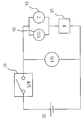
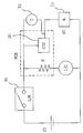
- FIGS. 1 to 3 are circuit diagrams illustrating an apparatus for automatically distinguishing a heater according to an exemplary embodiment of the present invention
- FIGS. 4 and 5 are perspective views illustrating the heater to which the apparatus for automatically distinguishing a heater according to an exemplary embodiment of the present invention is applied.
- FIG. 6 is an exploded perspective view illustrating a driving device of the apparatus for automatically distinguishing a heater according to the exemplary embodiment of the present invention.
- an apparatus for automatically distinguishing a heater includes an automatic sensing device having a carbon dioxide and carbon oxide sensor 30, a temperature sensor 40, or a timer 13 and is applied to a heater in which a wick 2 absorbing fuel is burnt to generate heat.
- the automatic sensing device may be made by the combinations of two sensing elements such as a combination of the carbon dioxide and carbon oxide sensor 30 and the timer 13 and of the temperature sensor 40 and the timer 13, or by a single element such as the timer 13, as illustrated in FIG. 3.
- the driving device 10 of the automatically distinguishing apparatus is driven under the control signal from a controller (not shown) such that the wick 2 that is burning is lowered down and is distinguished.
- the apparatus for automatically distinguishing a heater will be described as employing a timer 13, as illustrated in FIGS. 4 and 5, from the a carbon dioxide and carbon oxide sensor 30 a temperature sensor 40, and the timer 13 that transmit sensing signals to the controller such that the heater is automatically distinguished.
- the automatic distinguishing apparatus operated between the timer 13 setting time and a lever (not shown) of a wick elevator elevating the wick 2, includes a driving device 10 transmitting a driving force of the timer 13 to a plurality of assemblies as connection-operation devices.
- the automatic distinguishing apparatus includes a follower device 20 transmitting a force generated by striking of an operative lever 17 provided in the driving device 10 to the plurality of assemblies and lowering the wick 2 using the transmitted force.
- the driving device 10, as illustrated in FIG. 6, is installed on a base plate 11 having a fastening member (not shown) such that the automatic distinguishing apparatus may be installed at a specific placed.
- the timer 13 is a device informing a setting time to a user as the clockwork or the electric motor returns to the initial state when a desired time is set with the clockwork or the electric motor.
- a vibration motor 15 as a driving motor is driven by a control signal from the controller (not shown).
- the vibration motor 15 used as a vibration source is rotatably installed on the base plate 11.
- the vibration motor 15 is mounted on the upper end of a rotation bracket 16 including a bracket assembly having the operative lever 17 provided at the lower side.
- vibration motor 15 and the rotation bracket 16 is integrally formed with each other and rotate about a lever rotation shaft 161 on the base plate 11.
- a first elastic member 162 is connected between a side of the rotation bracket 16 located opposite to the operative lever 17 and the base plate 11.
- the first elastic member 162 makes the rotation bracket 16 and the operative lever 17 be smoothly rotated about the lever rotation shaft 161 when the rotation bracket 16 and the operative lever 17 are rotated by the centrifugal force of the vibration motor 15.
- the vibration motor 15 makes vibration while an eccentric weight 152 that is mounted on a motor shaft 151 rotates when a rotor (not shown) of the vibration motor 15 such that the vibration is generated by the eccentric weight 152 of the motor shaft 151 when the vibration motor 15 is rotated by a driving signal from the controller.
- the driving device 10 transmits the eccentric force of the vibration motor 15 that is driven by the controller to the operative lever 17 when the heater using time reaches at the setting time, and may substitute an existing mechanical devic e of an automatic distinguishing apparatus of a heater, in which a plurality of gear assemblies that are connected to each other are sequentially driven and transmit a rotational driving force.
- a micro-switch 18 in which a switch lever 181 is disposed parallel to the operative lever 17 is installed at a side of the rotation bracket 16.
- the controller received the off-signal from the micro-switch 18 transmits a stop command to the vibration motor 15.
- the power supplying state to the vibration motor 15 means a state that the controller senses the setting time of the timer 13 and transmits a control signal and a state that the carbon dioxide and carbon oxide sensor 30 and the temperature sensor 40 sense the quantity of carbon dioxide and carbon oxide and temperature in the heater under the control signal from the controller and transmit the sensed data.
- the switch lever 181 is not rotated by the lever rotation shaft 161 like the operative lever 17 but is made of an elastic material and is elastically deformed to perform a switching function.
- the operative lever 17, as described above, includes a spring connector 171 provided at a side from the lever rotation shaft 161 and connected to the first elastic member 162 and a striking unit 172 striking a side of the bracket latchet 22 that is provided to the follower device 20.
- the driving device 10 transmits the rotation driving force of the timer 13 to the operative lever 17 such that the rotation driving force of the timer 13 is transmitted to the follower device 20 while connected assemblies are sequentially rotated.
- the follower device 20 includes a plurality of assemblies and is installed a base bracket 21.
- the bracket latchet 22 includes the follower lever 221 provided at a side from a latchet rotation shaft 223 and making a contact with the operative lever 17 and a pin having a pawl function and provided at the opposite side to selectively restrict a later-described latchet gear 23 and rotates about the latchet rotation shaft 223.
- a reversed U-shaped elastic plate 224 is adjacent to and crosses a later-described wick driving shaft 25.
- One side of the elastic plate 224 is fixed to a rear end of the follower lever 221 of the bracket latchet 22 and the other side of the elastic plate 224 make a contact with a return lever 231 provided at the rear side of a later-described latchet gear 23.
- the latchet gear 23 rotates with the return lever 231 only in one direction by the pin 222 of the bracket latchet 22 and is provided on the same axis as a lever (not shown) elevating the wick 2.
- the latchet gear 23 as a latchet device is fixed to a wick driving shaft 25 connected to the lever (not shown) manually elevating the wick 2 in a combustion chamber 1 and rotates only in one direction due to the restriction by the pin 222 provided in the bracket latchet 22 as described above.
- the latchet gear 23 is restricted to rotate counter clockwise by the pin 222.
- the second elastic member 24, as illustrated in FIGS. 4 and 5, includes an end fixed to the wick driving shaft 25 and the other end fixed to a fixing body 211 of the base bracket 21 that is adj acent to the wick driving shaft 25.
- the second elastic member 24 may be a spring such as coil spring which is wound or released according to the rotation direction of the wick driving shaft 25 and a diameter of which is varied so as to store torsion energy when the wick driving shaft 25 rotat), and the present invention is not limited thereto.
- the automatic distinguishing apparatus drives the assemblies of the driving device 10 and the follower device 20 in the order of reverse to the operating order of the assemblies to set the initial state again.
- a restoring device returning the automatic distinguishing apparatus to the initial state is a return lever 231 which integrally protrudes from the rear side of the latchet gear 23 and which provides a thrust force to the elastic plate 224 instantly while rotating with the latchet gear 23 when the latchet gear 23 is not restricted by the pin 222 of the bracket latchet 22 and is rotated counter clockwise by the elastic restoring force of the second elastic member 24 that is fixed to the wick driving shaft 25.
- the return lever 231 provides the thrust force instantly to the opposite side of the elastic plate 224 crossing the wick driving shaft 25 and the side of the elastic plate 224 rotates about the latchet rotation shaft 223 with the bracket latchet 22.
- FIG. 7 is a view illustrating a state before the driving device of the apparatus for automatically distinguishing a heater according to the exemplary embodiment of the present invention is driven.
- FIG. 8 is a view illustrating a state after the driving device of the apparatus for automatically distinguishing a heater according to the exemplary embodiment of the present invention is driven.
- FIGS. 9 and 10 are views illustrating operative state of a follower device including the driving device of the apparatus for automatically distinguishing a heater according to the exemplary embodiment of the present invention.
- a lever (not shown) of the wick elevator coupled with the wick driving shaft 25 and elevating the wick 2 is rotated clockwise to elevate the wick 2 over the combustion chamber 1 and the wick 2 is lighted for heating.
- the second elastic member 24 wound around the wick driving shaft 25 exerts in the winding direction, the second elastic member 24 provides a return force in the opposite direction.
- the bracket latchet 22 as a device for restricting the return force of the second elastic member 24, which is adjacent to the wick driving shaft 25, restricts the counter clockwise rotation of the latchet gear 23 when the pin 222 provided in the bracket latchet 22 is engaged with teeth of the latch gear 23 that is fixed to the wick driving shaft 25.
- the using time is set by manipulating the lever (not shown) of the timer initial sequential operations of which are enabled.
- the timer 13 in which the using time is set is operated slowly in a preset rotation direction by clockwork or a motor.
- a using time finishing signal is transmitted to the controller and the controller transmits a driving signal to the vibration motor 15 of FIG. 7.
- the vibration motor 15 received the driving signal generates vibration due to rotation of the eccentric weight 152.
- the operative lever 17 strikes a side of the bracket latchet 22, that is, the follower leer 221, the bracket latchet 22 rotates about the latchet rotation shaft 223.
- the latchet gear 23 When the latchet gear 23 is released, the latchet gear 23 that is fixed to the wick driving shaft 25, as illustrated in FIG. 10, is rotated counter clockwise by the return force of the second elastic member 24 and the return lever 231 fixed to the rear side of the latchet gear 23 provides the pressing force to the elastic plate 224 of the bracket latchet 22 in association with the latchet gear 23.
- bracket latchet 22 rotates about the latchet 223 in a direction reverse to the initial operation direction and provides a thrust force to the operative lever 17 on the contrary to the initial operation and the operative lever 17 rotates in the initial state and returns to the original state so that the automatic distinguishing apparatus enters the initial setting state.
- the off signal is applied to the power supply of the vibration motor 15 when the follower lever 221 of the bracket latchet 22 returns to the original state and presses the switch lever 181 of the micro-switch 18 so that the vibration motor 15 driven by the driving signal from the controller is stopped to rotate.
- the switch lever 181 of the micro-switch 18 moves upward to the original state and the vibration motor 15 may be supplied with electric power.
Landscapes
- Engineering & Computer Science (AREA)
- Chemical & Material Sciences (AREA)
- Combustion & Propulsion (AREA)
- Mechanical Engineering (AREA)
- General Engineering & Computer Science (AREA)
- General Chemical & Material Sciences (AREA)
- Chemical Kinetics & Catalysis (AREA)
- Oil, Petroleum & Natural Gas (AREA)
- Health & Medical Sciences (AREA)
- Public Health (AREA)
- Business, Economics & Management (AREA)
- Emergency Management (AREA)
- Regulation And Control Of Combustion (AREA)
- Control Of Combustion (AREA)
- Direct Air Heating By Heater Or Combustion Gas (AREA)
Applications Claiming Priority (1)
| Application Number | Priority Date | Filing Date | Title |
|---|---|---|---|
| KR1020110045747A KR101129325B1 (ko) | 2011-05-16 | 2011-05-16 | 히터용 자동 소화장치 |
Publications (3)
| Publication Number | Publication Date |
|---|---|
| EP2525147A2 true EP2525147A2 (fr) | 2012-11-21 |
| EP2525147A3 EP2525147A3 (fr) | 2016-01-06 |
| EP2525147B1 EP2525147B1 (fr) | 2018-02-14 |
Family
ID=44674426
Family Applications (1)
| Application Number | Title | Priority Date | Filing Date |
|---|---|---|---|
| EP11179929.2A Active EP2525147B1 (fr) | 2011-05-16 | 2011-09-02 | Appareil pour éteindre automatiquement un appareil de chauffage |
Country Status (6)
| Country | Link |
|---|---|
| EP (1) | EP2525147B1 (fr) |
| JP (1) | JP5758047B2 (fr) |
| KR (1) | KR101129325B1 (fr) |
| CN (1) | CN103518101B (fr) |
| ES (1) | ES2671903T3 (fr) |
| WO (1) | WO2012157809A1 (fr) |
Cited By (3)
| Publication number | Priority date | Publication date | Assignee | Title |
|---|---|---|---|---|
| CN103557552A (zh) * | 2013-09-29 | 2014-02-05 | 王波兰 | 电暖器控制系统 |
| EP3002516A1 (fr) * | 2014-09-30 | 2016-04-06 | Paseco Co., Ltd. | Dispositif de chauffage possédant un extincteur automatique |
| US10408471B1 (en) | 2016-12-28 | 2019-09-10 | Lionel Lanouette | Wireless carbon monoxide furnace shutoff system |
Citations (1)
| Publication number | Priority date | Publication date | Assignee | Title |
|---|---|---|---|---|
| KR100982803B1 (ko) | 2009-12-08 | 2010-09-20 | 주식회사 파세코 | 히터용 자동 소화장치 |
Family Cites Families (9)
| Publication number | Priority date | Publication date | Assignee | Title |
|---|---|---|---|---|
| JPS57164211A (en) * | 1981-04-02 | 1982-10-08 | Shizuko Maruyama | Wick elevational movement type petroleum stove with automatic odorless fire extinguisher |
| JPS5862407A (ja) | 1981-10-09 | 1983-04-13 | Matsushita Electric Ind Co Ltd | 石油燃焼器 |
| JPS61130707A (ja) * | 1984-11-29 | 1986-06-18 | Matsushita Electric Ind Co Ltd | 灯芯式石油燃焼器の吸臭制御装置 |
| JPS61184316A (ja) * | 1985-02-07 | 1986-08-18 | Sharp Corp | 石油燃焼器の臭気低減装置 |
| JP2555008B2 (ja) * | 1985-04-19 | 1996-11-20 | 松下電工株式会社 | タイマ−回路 |
| JPH02110203A (ja) * | 1988-10-18 | 1990-04-23 | Hitachi Heating Appliance Co Ltd | 芯上下式石油ストーブ |
| KR950010474Y1 (ko) * | 1993-04-15 | 1995-12-14 | 박범규 | 가스밸브 개폐장치 |
| KR100381256B1 (ko) * | 2000-06-09 | 2003-04-23 | 주식회사 파세코 | 자동소화장치 |
| JP2006207978A (ja) | 2005-01-31 | 2006-08-10 | Toyotomi Co Ltd | 石油燃焼器の安全装置 |
-
2011
- 2011-05-16 KR KR1020110045747A patent/KR101129325B1/ko not_active Expired - Fee Related
- 2011-07-06 JP JP2014510229A patent/JP5758047B2/ja not_active Expired - Fee Related
- 2011-07-06 CN CN201180070785.4A patent/CN103518101B/zh not_active Expired - Fee Related
- 2011-07-06 WO PCT/KR2011/004924 patent/WO2012157809A1/fr not_active Ceased
- 2011-09-02 ES ES11179929.2T patent/ES2671903T3/es active Active
- 2011-09-02 EP EP11179929.2A patent/EP2525147B1/fr active Active
Patent Citations (1)
| Publication number | Priority date | Publication date | Assignee | Title |
|---|---|---|---|---|
| KR100982803B1 (ko) | 2009-12-08 | 2010-09-20 | 주식회사 파세코 | 히터용 자동 소화장치 |
Cited By (5)
| Publication number | Priority date | Publication date | Assignee | Title |
|---|---|---|---|---|
| CN103557552A (zh) * | 2013-09-29 | 2014-02-05 | 王波兰 | 电暖器控制系统 |
| EP3002516A1 (fr) * | 2014-09-30 | 2016-04-06 | Paseco Co., Ltd. | Dispositif de chauffage possédant un extincteur automatique |
| CN105465826A (zh) * | 2014-09-30 | 2016-04-06 | 帕饰克股份有限公司 | 具有自动熄火器的加热器 |
| CN105465826B (zh) * | 2014-09-30 | 2017-12-01 | 帕饰克股份有限公司 | 具有自动熄火器的加热器 |
| US10408471B1 (en) | 2016-12-28 | 2019-09-10 | Lionel Lanouette | Wireless carbon monoxide furnace shutoff system |
Also Published As
| Publication number | Publication date |
|---|---|
| ES2671903T3 (es) | 2018-06-11 |
| EP2525147B1 (fr) | 2018-02-14 |
| JP5758047B2 (ja) | 2015-08-05 |
| JP2014517902A (ja) | 2014-07-24 |
| EP2525147A3 (fr) | 2016-01-06 |
| WO2012157809A1 (fr) | 2012-11-22 |
| CN103518101B (zh) | 2016-01-27 |
| CN103518101A (zh) | 2014-01-15 |
| KR101129325B1 (ko) | 2012-03-26 |
Similar Documents
| Publication | Publication Date | Title |
|---|---|---|
| US9706872B2 (en) | Control device for gas taps | |
| EP2525147B1 (fr) | Appareil pour éteindre automatiquement un appareil de chauffage | |
| US4872831A (en) | Kerosene heater providing automatic wick repositioning after ignition | |
| KR100982803B1 (ko) | 히터용 자동 소화장치 | |
| CN103363556B (zh) | 用于加热器的自动关断装置 | |
| US1745178A (en) | Liquid-fuel-burner control | |
| JP2002013737A (ja) | 自動消火装置 | |
| JP2812155B2 (ja) | 自動小燃焼機構付石油燃焼器 | |
| EP0719985B1 (fr) | Brûleur à huile du type à réduction de combustion automatique | |
| CN219588168U (zh) | 一种点火阀及燃气灶 | |
| CN115435139B (zh) | 流量调节阀、家用电器的控制方法和家用电器 | |
| JP3127189B2 (ja) | ガスコンロの器具栓 | |
| EP1907756B1 (fr) | Appareil de cuisson | |
| JP2871376B2 (ja) | 自動小燃焼芯下機構付石油燃焼器 | |
| JP2645831B2 (ja) | 石油燃焼装置 | |
| JP3871795B2 (ja) | 加熱調理器の自動消火装置 | |
| US1405011A (en) | Device eor lighting- smtjdg-e pots | |
| KR19990049141A (ko) | 자동소화장치 | |
| JPS6137933Y2 (fr) | ||
| KR101133667B1 (ko) | 열풍기의 가스밸브 안전장치 | |
| JPS63217134A (ja) | 開放型燃焼器の安全装置 | |
| TWM347542U (en) | Knob-type igniter of gas cooking device | |
| JPH1163505A (ja) | ガスこんろ | |
| JP2871377B2 (ja) | 自動小燃焼芯下機構付石油燃焼器 | |
| JP2000329345A (ja) | 石油燃焼器の消火装置 |
Legal Events
| Date | Code | Title | Description |
|---|---|---|---|
| PUAI | Public reference made under article 153(3) epc to a published international application that has entered the european phase |
Free format text: ORIGINAL CODE: 0009012 |
|
| AK | Designated contracting states |
Kind code of ref document: A2 Designated state(s): AL AT BE BG CH CY CZ DE DK EE ES FI FR GB GR HR HU IE IS IT LI LT LU LV MC MK MT NL NO PL PT RO RS SE SI SK SM TR |
|
| AX | Request for extension of the european patent |
Extension state: BA ME |
|
| PUAL | Search report despatched |
Free format text: ORIGINAL CODE: 0009013 |
|
| AK | Designated contracting states |
Kind code of ref document: A3 Designated state(s): AL AT BE BG CH CY CZ DE DK EE ES FI FR GB GR HR HU IE IS IT LI LT LU LV MC MK MT NL NO PL PT RO RS SE SI SK SM TR |
|
| AX | Request for extension of the european patent |
Extension state: BA ME |
|
| RIC1 | Information provided on ipc code assigned before grant |
Ipc: F23D 3/26 20060101AFI20151130BHEP Ipc: F23N 5/22 20060101ALI20151130BHEP Ipc: F23N 5/00 20060101ALI20151130BHEP Ipc: F23N 5/24 20060101ALI20151130BHEP Ipc: F23N 5/02 20060101ALI20151130BHEP Ipc: F23D 3/28 20060101ALI20151130BHEP |
|
| 17P | Request for examination filed |
Effective date: 20160324 |
|
| RBV | Designated contracting states (corrected) |
Designated state(s): AL AT BE BG CH CY CZ DE DK EE ES FI FR GB GR HR HU IE IS IT LI LT LU LV MC MK MT NL NO PL PT RO RS SE SI SK SM TR |
|
| 17Q | First examination report despatched |
Effective date: 20170222 |
|
| GRAP | Despatch of communication of intention to grant a patent |
Free format text: ORIGINAL CODE: EPIDOSNIGR1 |
|
| INTG | Intention to grant announced |
Effective date: 20171011 |
|
| GRAS | Grant fee paid |
Free format text: ORIGINAL CODE: EPIDOSNIGR3 |
|
| GRAA | (expected) grant |
Free format text: ORIGINAL CODE: 0009210 |
|
| AK | Designated contracting states |
Kind code of ref document: B1 Designated state(s): AL AT BE BG CH CY CZ DE DK EE ES FI FR GB GR HR HU IE IS IT LI LT LU LV MC MK MT NL NO PL PT RO RS SE SI SK SM TR |
|
| REG | Reference to a national code |
Ref country code: GB Ref legal event code: FG4D |
|
| REG | Reference to a national code |
Ref country code: CH Ref legal event code: EP |
|
| REG | Reference to a national code |
Ref country code: IE Ref legal event code: FG4D |
|
| REG | Reference to a national code |
Ref country code: DE Ref legal event code: R096 Ref document number: 602011045592 Country of ref document: DE Ref country code: AT Ref legal event code: REF Ref document number: 970085 Country of ref document: AT Kind code of ref document: T Effective date: 20180315 |
|
| REG | Reference to a national code |
Ref country code: NL Ref legal event code: FP |
|
| REG | Reference to a national code |
Ref country code: ES Ref legal event code: FG2A Ref document number: 2671903 Country of ref document: ES Kind code of ref document: T3 Effective date: 20180611 |
|
| REG | Reference to a national code |
Ref country code: AT Ref legal event code: MK05 Ref document number: 970085 Country of ref document: AT Kind code of ref document: T Effective date: 20180214 |
|
| PG25 | Lapsed in a contracting state [announced via postgrant information from national office to epo] |
Ref country code: NO Free format text: LAPSE BECAUSE OF FAILURE TO SUBMIT A TRANSLATION OF THE DESCRIPTION OR TO PAY THE FEE WITHIN THE PRESCRIBED TIME-LIMIT Effective date: 20180514 Ref country code: CY Free format text: LAPSE BECAUSE OF FAILURE TO SUBMIT A TRANSLATION OF THE DESCRIPTION OR TO PAY THE FEE WITHIN THE PRESCRIBED TIME-LIMIT Effective date: 20180214 Ref country code: HR Free format text: LAPSE BECAUSE OF FAILURE TO SUBMIT A TRANSLATION OF THE DESCRIPTION OR TO PAY THE FEE WITHIN THE PRESCRIBED TIME-LIMIT Effective date: 20180214 Ref country code: LT Free format text: LAPSE BECAUSE OF FAILURE TO SUBMIT A TRANSLATION OF THE DESCRIPTION OR TO PAY THE FEE WITHIN THE PRESCRIBED TIME-LIMIT Effective date: 20180214 Ref country code: FI Free format text: LAPSE BECAUSE OF FAILURE TO SUBMIT A TRANSLATION OF THE DESCRIPTION OR TO PAY THE FEE WITHIN THE PRESCRIBED TIME-LIMIT Effective date: 20180214 |
|
| PG25 | Lapsed in a contracting state [announced via postgrant information from national office to epo] |
Ref country code: GR Free format text: LAPSE BECAUSE OF FAILURE TO SUBMIT A TRANSLATION OF THE DESCRIPTION OR TO PAY THE FEE WITHIN THE PRESCRIBED TIME-LIMIT Effective date: 20180515 Ref country code: AT Free format text: LAPSE BECAUSE OF FAILURE TO SUBMIT A TRANSLATION OF THE DESCRIPTION OR TO PAY THE FEE WITHIN THE PRESCRIBED TIME-LIMIT Effective date: 20180214 Ref country code: SE Free format text: LAPSE BECAUSE OF FAILURE TO SUBMIT A TRANSLATION OF THE DESCRIPTION OR TO PAY THE FEE WITHIN THE PRESCRIBED TIME-LIMIT Effective date: 20180214 Ref country code: LV Free format text: LAPSE BECAUSE OF FAILURE TO SUBMIT A TRANSLATION OF THE DESCRIPTION OR TO PAY THE FEE WITHIN THE PRESCRIBED TIME-LIMIT Effective date: 20180214 Ref country code: BG Free format text: LAPSE BECAUSE OF FAILURE TO SUBMIT A TRANSLATION OF THE DESCRIPTION OR TO PAY THE FEE WITHIN THE PRESCRIBED TIME-LIMIT Effective date: 20180514 Ref country code: RS Free format text: LAPSE BECAUSE OF FAILURE TO SUBMIT A TRANSLATION OF THE DESCRIPTION OR TO PAY THE FEE WITHIN THE PRESCRIBED TIME-LIMIT Effective date: 20180214 |
|
| REG | Reference to a national code |
Ref country code: FR Ref legal event code: PLFP Year of fee payment: 8 |
|
| PG25 | Lapsed in a contracting state [announced via postgrant information from national office to epo] |
Ref country code: PL Free format text: LAPSE BECAUSE OF FAILURE TO SUBMIT A TRANSLATION OF THE DESCRIPTION OR TO PAY THE FEE WITHIN THE PRESCRIBED TIME-LIMIT Effective date: 20180214 Ref country code: AL Free format text: LAPSE BECAUSE OF FAILURE TO SUBMIT A TRANSLATION OF THE DESCRIPTION OR TO PAY THE FEE WITHIN THE PRESCRIBED TIME-LIMIT Effective date: 20180214 Ref country code: RO Free format text: LAPSE BECAUSE OF FAILURE TO SUBMIT A TRANSLATION OF THE DESCRIPTION OR TO PAY THE FEE WITHIN THE PRESCRIBED TIME-LIMIT Effective date: 20180214 Ref country code: EE Free format text: LAPSE BECAUSE OF FAILURE TO SUBMIT A TRANSLATION OF THE DESCRIPTION OR TO PAY THE FEE WITHIN THE PRESCRIBED TIME-LIMIT Effective date: 20180214 |
|
| REG | Reference to a national code |
Ref country code: DE Ref legal event code: R097 Ref document number: 602011045592 Country of ref document: DE |
|
| PG25 | Lapsed in a contracting state [announced via postgrant information from national office to epo] |
Ref country code: CZ Free format text: LAPSE BECAUSE OF FAILURE TO SUBMIT A TRANSLATION OF THE DESCRIPTION OR TO PAY THE FEE WITHIN THE PRESCRIBED TIME-LIMIT Effective date: 20180214 Ref country code: SM Free format text: LAPSE BECAUSE OF FAILURE TO SUBMIT A TRANSLATION OF THE DESCRIPTION OR TO PAY THE FEE WITHIN THE PRESCRIBED TIME-LIMIT Effective date: 20180214 Ref country code: DK Free format text: LAPSE BECAUSE OF FAILURE TO SUBMIT A TRANSLATION OF THE DESCRIPTION OR TO PAY THE FEE WITHIN THE PRESCRIBED TIME-LIMIT Effective date: 20180214 Ref country code: SK Free format text: LAPSE BECAUSE OF FAILURE TO SUBMIT A TRANSLATION OF THE DESCRIPTION OR TO PAY THE FEE WITHIN THE PRESCRIBED TIME-LIMIT Effective date: 20180214 |
|
| PLBE | No opposition filed within time limit |
Free format text: ORIGINAL CODE: 0009261 |
|
| STAA | Information on the status of an ep patent application or granted ep patent |
Free format text: STATUS: NO OPPOSITION FILED WITHIN TIME LIMIT |
|
| 26N | No opposition filed |
Effective date: 20181115 |
|
| PG25 | Lapsed in a contracting state [announced via postgrant information from national office to epo] |
Ref country code: SI Free format text: LAPSE BECAUSE OF FAILURE TO SUBMIT A TRANSLATION OF THE DESCRIPTION OR TO PAY THE FEE WITHIN THE PRESCRIBED TIME-LIMIT Effective date: 20180214 |
|
| REG | Reference to a national code |
Ref country code: DE Ref legal event code: R119 Ref document number: 602011045592 Country of ref document: DE |
|
| PG25 | Lapsed in a contracting state [announced via postgrant information from national office to epo] |
Ref country code: MC Free format text: LAPSE BECAUSE OF FAILURE TO SUBMIT A TRANSLATION OF THE DESCRIPTION OR TO PAY THE FEE WITHIN THE PRESCRIBED TIME-LIMIT Effective date: 20180214 |
|
| REG | Reference to a national code |
Ref country code: CH Ref legal event code: PL |
|
| GBPC | Gb: european patent ceased through non-payment of renewal fee |
Effective date: 20180902 |
|
| REG | Reference to a national code |
Ref country code: IE Ref legal event code: MM4A |
|
| PG25 | Lapsed in a contracting state [announced via postgrant information from national office to epo] |
Ref country code: LU Free format text: LAPSE BECAUSE OF NON-PAYMENT OF DUE FEES Effective date: 20180902 |
|
| PG25 | Lapsed in a contracting state [announced via postgrant information from national office to epo] |
Ref country code: IE Free format text: LAPSE BECAUSE OF NON-PAYMENT OF DUE FEES Effective date: 20180902 Ref country code: DE Free format text: LAPSE BECAUSE OF NON-PAYMENT OF DUE FEES Effective date: 20190402 |
|
| PG25 | Lapsed in a contracting state [announced via postgrant information from national office to epo] |
Ref country code: CH Free format text: LAPSE BECAUSE OF NON-PAYMENT OF DUE FEES Effective date: 20180930 Ref country code: LI Free format text: LAPSE BECAUSE OF NON-PAYMENT OF DUE FEES Effective date: 20180930 |
|
| PG25 | Lapsed in a contracting state [announced via postgrant information from national office to epo] |
Ref country code: GB Free format text: LAPSE BECAUSE OF NON-PAYMENT OF DUE FEES Effective date: 20180902 |
|
| PG25 | Lapsed in a contracting state [announced via postgrant information from national office to epo] |
Ref country code: MT Free format text: LAPSE BECAUSE OF NON-PAYMENT OF DUE FEES Effective date: 20180902 |
|
| PG25 | Lapsed in a contracting state [announced via postgrant information from national office to epo] |
Ref country code: TR Free format text: LAPSE BECAUSE OF FAILURE TO SUBMIT A TRANSLATION OF THE DESCRIPTION OR TO PAY THE FEE WITHIN THE PRESCRIBED TIME-LIMIT Effective date: 20180214 |
|
| PG25 | Lapsed in a contracting state [announced via postgrant information from national office to epo] |
Ref country code: PT Free format text: LAPSE BECAUSE OF FAILURE TO SUBMIT A TRANSLATION OF THE DESCRIPTION OR TO PAY THE FEE WITHIN THE PRESCRIBED TIME-LIMIT Effective date: 20180214 Ref country code: HU Free format text: LAPSE BECAUSE OF FAILURE TO SUBMIT A TRANSLATION OF THE DESCRIPTION OR TO PAY THE FEE WITHIN THE PRESCRIBED TIME-LIMIT; INVALID AB INITIO Effective date: 20110902 |
|
| PG25 | Lapsed in a contracting state [announced via postgrant information from national office to epo] |
Ref country code: MK Free format text: LAPSE BECAUSE OF NON-PAYMENT OF DUE FEES Effective date: 20180214 |
|
| PG25 | Lapsed in a contracting state [announced via postgrant information from national office to epo] |
Ref country code: IS Free format text: LAPSE BECAUSE OF FAILURE TO SUBMIT A TRANSLATION OF THE DESCRIPTION OR TO PAY THE FEE WITHIN THE PRESCRIBED TIME-LIMIT Effective date: 20180614 |
|
| PGFP | Annual fee paid to national office [announced via postgrant information from national office to epo] |
Ref country code: NL Payment date: 20250918 Year of fee payment: 15 Ref country code: IT Payment date: 20250923 Year of fee payment: 15 |
|
| PGFP | Annual fee paid to national office [announced via postgrant information from national office to epo] |
Ref country code: BE Payment date: 20250918 Year of fee payment: 15 |
|
| PGFP | Annual fee paid to national office [announced via postgrant information from national office to epo] |
Ref country code: FR Payment date: 20250922 Year of fee payment: 15 |
|
| PGFP | Annual fee paid to national office [announced via postgrant information from national office to epo] |
Ref country code: ES Payment date: 20251028 Year of fee payment: 15 |