EP2525078A2 - Engine start control system for hybrid electric vehicle - Google Patents
Engine start control system for hybrid electric vehicle Download PDFInfo
- Publication number
- EP2525078A2 EP2525078A2 EP12001435A EP12001435A EP2525078A2 EP 2525078 A2 EP2525078 A2 EP 2525078A2 EP 12001435 A EP12001435 A EP 12001435A EP 12001435 A EP12001435 A EP 12001435A EP 2525078 A2 EP2525078 A2 EP 2525078A2
- Authority
- EP
- European Patent Office
- Prior art keywords
- engine
- engine start
- motor
- cranking torque
- torque
- Prior art date
- Legal status (The legal status is an assumption and is not a legal conclusion. Google has not performed a legal analysis and makes no representation as to the accuracy of the status listed.)
- Granted
Links
Images




Classifications
-
- B—PERFORMING OPERATIONS; TRANSPORTING
- B60—VEHICLES IN GENERAL
- B60W—CONJOINT CONTROL OF VEHICLE SUB-UNITS OF DIFFERENT TYPE OR DIFFERENT FUNCTION; CONTROL SYSTEMS SPECIALLY ADAPTED FOR HYBRID VEHICLES; ROAD VEHICLE DRIVE CONTROL SYSTEMS FOR PURPOSES NOT RELATED TO THE CONTROL OF A PARTICULAR SUB-UNIT
- B60W20/00—Control systems specially adapted for hybrid vehicles
-
- B—PERFORMING OPERATIONS; TRANSPORTING
- B60—VEHICLES IN GENERAL
- B60K—ARRANGEMENT OR MOUNTING OF PROPULSION UNITS OR OF TRANSMISSIONS IN VEHICLES; ARRANGEMENT OR MOUNTING OF PLURAL DIVERSE PRIME-MOVERS IN VEHICLES; AUXILIARY DRIVES FOR VEHICLES; INSTRUMENTATION OR DASHBOARDS FOR VEHICLES; ARRANGEMENTS IN CONNECTION WITH COOLING, AIR INTAKE, GAS EXHAUST OR FUEL SUPPLY OF PROPULSION UNITS IN VEHICLES
- B60K6/00—Arrangement or mounting of plural diverse prime-movers for mutual or common propulsion, e.g. hybrid propulsion systems comprising electric motors and internal combustion engines
- B60K6/20—Arrangement or mounting of plural diverse prime-movers for mutual or common propulsion, e.g. hybrid propulsion systems comprising electric motors and internal combustion engines the prime-movers consisting of electric motors and internal combustion engines, e.g. HEVs
- B60K6/42—Arrangement or mounting of plural diverse prime-movers for mutual or common propulsion, e.g. hybrid propulsion systems comprising electric motors and internal combustion engines the prime-movers consisting of electric motors and internal combustion engines, e.g. HEVs characterised by the architecture of the hybrid electric vehicle
- B60K6/48—Parallel type
-
- B—PERFORMING OPERATIONS; TRANSPORTING
- B60—VEHICLES IN GENERAL
- B60W—CONJOINT CONTROL OF VEHICLE SUB-UNITS OF DIFFERENT TYPE OR DIFFERENT FUNCTION; CONTROL SYSTEMS SPECIALLY ADAPTED FOR HYBRID VEHICLES; ROAD VEHICLE DRIVE CONTROL SYSTEMS FOR PURPOSES NOT RELATED TO THE CONTROL OF A PARTICULAR SUB-UNIT
- B60W10/00—Conjoint control of vehicle sub-units of different type or different function
- B60W10/02—Conjoint control of vehicle sub-units of different type or different function including control of driveline clutches
-
- B—PERFORMING OPERATIONS; TRANSPORTING
- B60—VEHICLES IN GENERAL
- B60W—CONJOINT CONTROL OF VEHICLE SUB-UNITS OF DIFFERENT TYPE OR DIFFERENT FUNCTION; CONTROL SYSTEMS SPECIALLY ADAPTED FOR HYBRID VEHICLES; ROAD VEHICLE DRIVE CONTROL SYSTEMS FOR PURPOSES NOT RELATED TO THE CONTROL OF A PARTICULAR SUB-UNIT
- B60W10/00—Conjoint control of vehicle sub-units of different type or different function
- B60W10/04—Conjoint control of vehicle sub-units of different type or different function including control of propulsion units
- B60W10/06—Conjoint control of vehicle sub-units of different type or different function including control of propulsion units including control of combustion engines
-
- B—PERFORMING OPERATIONS; TRANSPORTING
- B60—VEHICLES IN GENERAL
- B60W—CONJOINT CONTROL OF VEHICLE SUB-UNITS OF DIFFERENT TYPE OR DIFFERENT FUNCTION; CONTROL SYSTEMS SPECIALLY ADAPTED FOR HYBRID VEHICLES; ROAD VEHICLE DRIVE CONTROL SYSTEMS FOR PURPOSES NOT RELATED TO THE CONTROL OF A PARTICULAR SUB-UNIT
- B60W10/00—Conjoint control of vehicle sub-units of different type or different function
- B60W10/04—Conjoint control of vehicle sub-units of different type or different function including control of propulsion units
- B60W10/08—Conjoint control of vehicle sub-units of different type or different function including control of propulsion units including control of electric propulsion units, e.g. motors or generators
-
- F—MECHANICAL ENGINEERING; LIGHTING; HEATING; WEAPONS; BLASTING
- F02—COMBUSTION ENGINES; HOT-GAS OR COMBUSTION-PRODUCT ENGINE PLANTS
- F02N—STARTING OF COMBUSTION ENGINES; STARTING AIDS FOR SUCH ENGINES, NOT OTHERWISE PROVIDED FOR
- F02N11/00—Starting of engines by means of electric motors
- F02N11/04—Starting of engines by means of electric motors the motors being associated with current generators
-
- F—MECHANICAL ENGINEERING; LIGHTING; HEATING; WEAPONS; BLASTING
- F02—COMBUSTION ENGINES; HOT-GAS OR COMBUSTION-PRODUCT ENGINE PLANTS
- F02N—STARTING OF COMBUSTION ENGINES; STARTING AIDS FOR SUCH ENGINES, NOT OTHERWISE PROVIDED FOR
- F02N11/00—Starting of engines by means of electric motors
- F02N11/08—Circuits specially adapted for starting of engines
- F02N11/0814—Circuits specially adapted for starting of engines comprising means for controlling automatic idle-start-stop
- F02N11/0818—Conditions for starting or stopping the engine or for deactivating the idle-start-stop mode
- F02N11/0822—Conditions for starting or stopping the engine or for deactivating the idle-start-stop mode related to action of the driver
-
- F—MECHANICAL ENGINEERING; LIGHTING; HEATING; WEAPONS; BLASTING
- F02—COMBUSTION ENGINES; HOT-GAS OR COMBUSTION-PRODUCT ENGINE PLANTS
- F02N—STARTING OF COMBUSTION ENGINES; STARTING AIDS FOR SUCH ENGINES, NOT OTHERWISE PROVIDED FOR
- F02N15/00—Other power-operated starting apparatus; Component parts, details, or accessories, not provided for in, or of interest apart from groups F02N5/00 - F02N13/00
- F02N15/02—Gearing between starting-engines and started engines; Engagement or disengagement thereof
- F02N15/022—Gearing between starting-engines and started engines; Engagement or disengagement thereof the starter comprising an intermediate clutch
-
- B—PERFORMING OPERATIONS; TRANSPORTING
- B60—VEHICLES IN GENERAL
- B60K—ARRANGEMENT OR MOUNTING OF PROPULSION UNITS OR OF TRANSMISSIONS IN VEHICLES; ARRANGEMENT OR MOUNTING OF PLURAL DIVERSE PRIME-MOVERS IN VEHICLES; AUXILIARY DRIVES FOR VEHICLES; INSTRUMENTATION OR DASHBOARDS FOR VEHICLES; ARRANGEMENTS IN CONNECTION WITH COOLING, AIR INTAKE, GAS EXHAUST OR FUEL SUPPLY OF PROPULSION UNITS IN VEHICLES
- B60K6/00—Arrangement or mounting of plural diverse prime-movers for mutual or common propulsion, e.g. hybrid propulsion systems comprising electric motors and internal combustion engines
- B60K6/20—Arrangement or mounting of plural diverse prime-movers for mutual or common propulsion, e.g. hybrid propulsion systems comprising electric motors and internal combustion engines the prime-movers consisting of electric motors and internal combustion engines, e.g. HEVs
- B60K6/22—Arrangement or mounting of plural diverse prime-movers for mutual or common propulsion, e.g. hybrid propulsion systems comprising electric motors and internal combustion engines the prime-movers consisting of electric motors and internal combustion engines, e.g. HEVs characterised by apparatus, components or means specially adapted for HEVs
- B60K6/26—Arrangement or mounting of plural diverse prime-movers for mutual or common propulsion, e.g. hybrid propulsion systems comprising electric motors and internal combustion engines the prime-movers consisting of electric motors and internal combustion engines, e.g. HEVs characterised by apparatus, components or means specially adapted for HEVs characterised by the motors or the generators
- B60K2006/268—Electric drive motor starts the engine, i.e. used as starter motor
-
- B—PERFORMING OPERATIONS; TRANSPORTING
- B60—VEHICLES IN GENERAL
- B60W—CONJOINT CONTROL OF VEHICLE SUB-UNITS OF DIFFERENT TYPE OR DIFFERENT FUNCTION; CONTROL SYSTEMS SPECIALLY ADAPTED FOR HYBRID VEHICLES; ROAD VEHICLE DRIVE CONTROL SYSTEMS FOR PURPOSES NOT RELATED TO THE CONTROL OF A PARTICULAR SUB-UNIT
- B60W20/00—Control systems specially adapted for hybrid vehicles
- B60W20/40—Controlling the engagement or disengagement of prime movers, e.g. for transition between prime movers
-
- B—PERFORMING OPERATIONS; TRANSPORTING
- B60—VEHICLES IN GENERAL
- B60W—CONJOINT CONTROL OF VEHICLE SUB-UNITS OF DIFFERENT TYPE OR DIFFERENT FUNCTION; CONTROL SYSTEMS SPECIALLY ADAPTED FOR HYBRID VEHICLES; ROAD VEHICLE DRIVE CONTROL SYSTEMS FOR PURPOSES NOT RELATED TO THE CONTROL OF A PARTICULAR SUB-UNIT
- B60W2510/00—Input parameters relating to a particular sub-units
- B60W2510/06—Combustion engines, Gas turbines
- B60W2510/0685—Engine crank angle
-
- B—PERFORMING OPERATIONS; TRANSPORTING
- B60—VEHICLES IN GENERAL
- B60W—CONJOINT CONTROL OF VEHICLE SUB-UNITS OF DIFFERENT TYPE OR DIFFERENT FUNCTION; CONTROL SYSTEMS SPECIALLY ADAPTED FOR HYBRID VEHICLES; ROAD VEHICLE DRIVE CONTROL SYSTEMS FOR PURPOSES NOT RELATED TO THE CONTROL OF A PARTICULAR SUB-UNIT
- B60W2540/00—Input parameters relating to occupants
- B60W2540/10—Accelerator pedal position
-
- B—PERFORMING OPERATIONS; TRANSPORTING
- B60—VEHICLES IN GENERAL
- B60W—CONJOINT CONTROL OF VEHICLE SUB-UNITS OF DIFFERENT TYPE OR DIFFERENT FUNCTION; CONTROL SYSTEMS SPECIALLY ADAPTED FOR HYBRID VEHICLES; ROAD VEHICLE DRIVE CONTROL SYSTEMS FOR PURPOSES NOT RELATED TO THE CONTROL OF A PARTICULAR SUB-UNIT
- B60W2710/00—Output or target parameters relating to a particular sub-units
- B60W2710/06—Combustion engines, Gas turbines
- B60W2710/0644—Engine speed
-
- B—PERFORMING OPERATIONS; TRANSPORTING
- B60—VEHICLES IN GENERAL
- B60W—CONJOINT CONTROL OF VEHICLE SUB-UNITS OF DIFFERENT TYPE OR DIFFERENT FUNCTION; CONTROL SYSTEMS SPECIALLY ADAPTED FOR HYBRID VEHICLES; ROAD VEHICLE DRIVE CONTROL SYSTEMS FOR PURPOSES NOT RELATED TO THE CONTROL OF A PARTICULAR SUB-UNIT
- B60W2710/00—Output or target parameters relating to a particular sub-units
- B60W2710/06—Combustion engines, Gas turbines
- B60W2710/0666—Engine torque
-
- F—MECHANICAL ENGINEERING; LIGHTING; HEATING; WEAPONS; BLASTING
- F02—COMBUSTION ENGINES; HOT-GAS OR COMBUSTION-PRODUCT ENGINE PLANTS
- F02N—STARTING OF COMBUSTION ENGINES; STARTING AIDS FOR SUCH ENGINES, NOT OTHERWISE PROVIDED FOR
- F02N2200/00—Parameters used for control of starting apparatus
- F02N2200/02—Parameters used for control of starting apparatus said parameters being related to the engine
- F02N2200/021—Engine crank angle
-
- F—MECHANICAL ENGINEERING; LIGHTING; HEATING; WEAPONS; BLASTING
- F02—COMBUSTION ENGINES; HOT-GAS OR COMBUSTION-PRODUCT ENGINE PLANTS
- F02N—STARTING OF COMBUSTION ENGINES; STARTING AIDS FOR SUCH ENGINES, NOT OTHERWISE PROVIDED FOR
- F02N2200/00—Parameters used for control of starting apparatus
- F02N2200/10—Parameters used for control of starting apparatus said parameters being related to driver demands or status
- F02N2200/101—Accelerator pedal position
-
- F—MECHANICAL ENGINEERING; LIGHTING; HEATING; WEAPONS; BLASTING
- F02—COMBUSTION ENGINES; HOT-GAS OR COMBUSTION-PRODUCT ENGINE PLANTS
- F02N—STARTING OF COMBUSTION ENGINES; STARTING AIDS FOR SUCH ENGINES, NOT OTHERWISE PROVIDED FOR
- F02N2300/00—Control related aspects of engine starting
- F02N2300/10—Control related aspects of engine starting characterised by the control output, i.e. means or parameters used as a control output or target
- F02N2300/104—Control of the starter motor torque
-
- F—MECHANICAL ENGINEERING; LIGHTING; HEATING; WEAPONS; BLASTING
- F02—COMBUSTION ENGINES; HOT-GAS OR COMBUSTION-PRODUCT ENGINE PLANTS
- F02N—STARTING OF COMBUSTION ENGINES; STARTING AIDS FOR SUCH ENGINES, NOT OTHERWISE PROVIDED FOR
- F02N2300/00—Control related aspects of engine starting
- F02N2300/20—Control related aspects of engine starting characterised by the control method
- F02N2300/2002—Control related aspects of engine starting characterised by the control method using different starting modes, methods, or actuators depending on circumstances, e.g. engine temperature or component wear
-
- Y—GENERAL TAGGING OF NEW TECHNOLOGICAL DEVELOPMENTS; GENERAL TAGGING OF CROSS-SECTIONAL TECHNOLOGIES SPANNING OVER SEVERAL SECTIONS OF THE IPC; TECHNICAL SUBJECTS COVERED BY FORMER USPC CROSS-REFERENCE ART COLLECTIONS [XRACs] AND DIGESTS
- Y02—TECHNOLOGIES OR APPLICATIONS FOR MITIGATION OR ADAPTATION AGAINST CLIMATE CHANGE
- Y02T—CLIMATE CHANGE MITIGATION TECHNOLOGIES RELATED TO TRANSPORTATION
- Y02T10/00—Road transport of goods or passengers
- Y02T10/10—Internal combustion engine [ICE] based vehicles
- Y02T10/40—Engine management systems
-
- Y—GENERAL TAGGING OF NEW TECHNOLOGICAL DEVELOPMENTS; GENERAL TAGGING OF CROSS-SECTIONAL TECHNOLOGIES SPANNING OVER SEVERAL SECTIONS OF THE IPC; TECHNICAL SUBJECTS COVERED BY FORMER USPC CROSS-REFERENCE ART COLLECTIONS [XRACs] AND DIGESTS
- Y02—TECHNOLOGIES OR APPLICATIONS FOR MITIGATION OR ADAPTATION AGAINST CLIMATE CHANGE
- Y02T—CLIMATE CHANGE MITIGATION TECHNOLOGIES RELATED TO TRANSPORTATION
- Y02T10/00—Road transport of goods or passengers
- Y02T10/60—Other road transportation technologies with climate change mitigation effect
- Y02T10/62—Hybrid vehicles
Definitions
- the present invention relates to an engine start control system, and in particular pertains to a cranking torque control technique at an engine start for a hybrid electric vehicle (HEV).
- HEV has a power train comprised of an engine, a first clutch, motor / generator, a second clutch and driving wheels as the torque transmission path arranged in these order and has two driving modes by selectively controlling an engagement or release of the first and second clutches so that the vehicle may be either electrically driven by the motor/generator only, or may be driven by both the engine and the motor/generator under a hybrid mode.
- a so-called one-motor, two-clutch, parallel hybrid vehicle in which a motor/generator is interposed between the engine and driving wheels, and the power transmission path between the engine and motor/generator may be selectively established by a first clutch, while the power transmission path between the motor/generator and the driving wheels may be selectively releasable by the second clutch.
- the HEV may select an EV mode by releasing the first clutch with the second clutch engaged so that the vehicle is driven by the motor/generator only.
- the HEV may alternatively select a HEV mode by engaging both the first and second clutches so that the vehicle runs under a collaboration of the engine and motor/generator.
- the rated torque of motor/generator has a sufficient amount that can meet a sum of EV running torque and an cranking torque required for engine starting .
- the EV running torque is comprised of the driving torque indicating a torque corresponding to the running resistance of the vehicle (i.e., air resistance, rolling resistance, etc.) plus an acceleration torque margin that is defined to correspond to a prescribed vehicle acceleration.
- cranking torque portion it is a common practice to set the cranking torque portion relatively larger than necessary based on the maximum acceleration performance so that engine will be started even in situations that require the greatest acceleration in response to a maximum acceleration request, and the driving force or torque of the vehicle will be increased without delay and in accordance to the request. Therefore, in the situations where the required acceleration of the vehicle is small, the cranking torque portion may be excessive as compared to the required acceleration. Consequently, when the required acceleration is small, the above driving torque portion which may be obtained by deducting the acceleration torque margin and cranking torque portion from the rated torque becomes small.
- the present invention was made based on the recognition that the above problem is attributable to the fact that the cranking torque portion which has been set larger in view of the required maximum acceleration and is applied or used as such even to the situation in which only a smaller degree of acceleration is required. Therefore, according to the present invention, the object resides in providing an engine start control system in which the cranking torque portion s adjusted and applied depending on the magnitude of the required acceleration such that an excessive cranking torque portion is avoided to be given when a required acceleration is small such that the above problem of a bad vehicle fuel efficiency due to a small region of EV mode operation may not be encountered.
- the engine start control system is outlined below.
- the HEV includes along the torque path/driveline from upstream side, an engine, a first clutch, a motor/generator, a second clutch, and driving wheels in these order.
- operation modes are selectable, and the vehicle may be driven electrically by the motor/generator only, or instead, driven under a hybrid mode by both the engine and motor/generator.
- the engine start control system to be used in the HEV is generally configured to start the engine by connecting the above first clutch for supplying a cranking torque portion from the motor/generator.
- the engine start control system may be characterized by a cranking torque portion changes or adjustment means to reduce cranking torque portion at a low vehicle acceleration demand or requirement.
- cranking torque portion is adjusted to be small when the required acceleration of the vehicle is small, no excessive cranking torque portion is applied when the required acceleration is small.
- the driving torque which is determined by deducing the cranking torque portion from the rated torque of motor/generator will not be small, so that the occurrence of such a situation may be put off in which the electrical running by the motor/generator only will not be possible (and thus compelled to switch to a hybrid running mode) with the result that the electric driving region to be intended for better fuel consumption may be expanded to more high-vehicle speed region and the worsening of the aforementioned problems of deterioration of fuel efficiency may be resolved.
- a powertrain for a hybrid vehicle with an engine start control system is schematically shown.
- This HEV is obtained by doing alterations on a conventional front engine, front wheel drive vehicle (Front wheel drive vehicle) as a base platform.
- reference 1 denotes an engine as power source
- 2FL and 2FR denote left front wheel and right front wheel, respectively, i.e., left and right driving wheels
- 3RL denotes a left rear wheel and right rear wheel (left right driven wheels)
- a V-belt continuous variable transmission (CVT) 4 is positioned in a transverse direction of the vehicle on a side of the transverse engine 1 to convey a rotation of the engine (i.e., crank shaft 1a thereof) to an axis 5 for transfer to an input shaft 4a of CVT 4 via motor/generator (M/G) 6 by operating (M/G) 6 as a power source.
- M/G motor/generator
- Motor/generator 6 has an annular stator 6a mounted within a housing and a rotor 6b coaxially disposed within stator 6a mounted within a housing and a rotor 6b coaxially disposed within stator 6a with a preset amount of gap, and responsive to the driving condition associated command, motor/generator 6 is intended to function either as an electric motor (electric motive) or as a generator. Motor/generator 6 is placed between the engine 1 and CVT 4. Motor/generator 6 has the above mentioned axis connected to and through the center of the rotor 6b and uses this axis 5 as a motor/generator axis.
- first clutch 7 is configure to continuously vary the transmission torque capacity (clutch engagement capacity) and, for example, may be composed, for example, by a wet type multi-plate clutch whose transfer torque capacity (clutch capacity) may be changed by continuously controlling a clutch operating oil flow rate and clutch operative pressure by a linear solenoid valve.
- V-belt CVT 4 may be of the conventional type in which a torque converter is removed and motor/generator 6 is directly connected to transmission input shaft 4a instead.
- V-belt CVT The rotation of output shaft 4b of V-belt CVT is transmitted to and distributed via differential gear unit (not shown) to left and right front wheels 2FL, 2FR for propulsion of the vehicle. It should be noted that the V-belt CVT may be replaced by a step automatic transmission.
- second clutch 9 that is indispensable to a hybrid vehicle for selectively engaging motor/generator 6 with driving wheels 2FL, 2FR may be disposed in a downstream side of the V-belt CVT 4, instead of being interposed in the transmission input shaft 4a, as shown in Fig. 1 .
- second clutch 9 may change a transmission torque capacity (clutch engagement capacity) continuously as in the case of first clutch 7.
- motor/generator 6 While driving in the HEV running mode, when a surplus energy is produced by operating the engine 1 at an optimum fuel consumption, motor/generator 6 will be allowed to operate as a generator for the excess energy to be converted into electricity energy such that the electricity power generated will stored in a battery for future use of the motor/generator 6 for a motor operation to thereby improve fuel efficiency of the engine 1.
- the selection of the above described EV mode and HEV mode may be conducted as follows; When vehicle speed is below a predetermined value (e.g., below 30 km/h), and accelerator opening is less than a predetermined openness (e.g., below 1/8) or change rate of accelerator opening is less that a predetermined acceleration command (e.g.,0.05G), motor/generator speed is less than a predetermined motor speed (e.g., 1000 rpm or less), engine cooling water temperature is more than a predetermined value (e.g., 40 °C or more) and finally battery storage condition, SOC (state of charge) exceeds a preset storage condition (e.g., 60% or more), then an EV mode is commanded and the vehicle is driven solely electrically, i.e., by motor/generator 6 only.
- a predetermined acceleration command e.g.,0.05G
- motor/generator speed is less than a predetermined motor speed (e.g., 1000 rpm or less)
- a HEV mode will be commanded for a hybrid (HEV) driving under coordinated operations of engine 1 with motor/generator 6.
- the control system comprises a controller 11 for controlling a hybrid powertrain operating point in a collaborative or coordinated way.
- the operating point of the powertrain may be defined by a target engine torque tTe, a target motor / generator torque tTm, a target engaging capacity of first clutch 7, tTc1 (first clutch engaging pressure command value tPc1), and a target engaging capacity of second clutch 9, tTc2 (second clutch engaging pressure command value tPc2).
- the hybrid controller 11 is supplied with a plurality of signals including a signal from engine rotation speed sensor 12 that detects an engine rotation speed Ne, a signal from motor/generator rotation speed sensor 13 that detects a rotation speed of motor/generator Nm, a signal from input rotation speed sensor 14 that detects a rotation speed of the transmission input Ni, a signal of output rotation speed sensor 15 that detects a transmission output rotation speed No (vehicle speed VSP), a signal of accelerator pedal openness sensor 16 that detects an accelerator pedal stroke (accelerator opening AP0), a signal from storage condition sensor 17 that detects a storage condition or state of charge (SOC) of battery 31 for storing electricity power for motor/generator 6, and finally a signal from an engine stop position sensor 18 that detect a crank angle a at which engine 1 has stopped.
- a signal from engine rotation speed sensor 12 that detects an engine rotation speed Ne
- a signal from motor/generator rotation speed sensor 13 that detects a rotation speed of motor/generator Nm
- Hybrid controller 11 selects an operation mode (EV mode or HEV mode) that can achieve the driving power the driver desires based on the accelerator opening degree AP0, battery storage condition SOC, and transmission output rotation speed No (i.e., vehicle speed, VSP) among the above referenced information.
- the hybrid controller 11 calculates a target engine torque tTe, target motor/generator torque tTm, target first clutch engaging capacity tTc1, and target second clutch engaging capacity tTc2, respectively.
- the target engine torque, tTe is supplied to the engine controller 32.
- the controller 32 controls engine 1 to attain the target engine torque tTe by employing controls such as a throttle opening control and fuel injection quantity control under a prevailing engine speed Ne based on the engine rotation speed Ne detected by sensor 12 and the target engine torque tTe supplied.
- the target motor / generator torque tTm is supplied to the motor controller 33.
- the motor controller 33 in turn operates to convert a direct current from the battery 31 to alternate current by inverter 34, or supplies the inverted current to a stator 6a of motor/generator 6 under the control of inverter 34 to control motor/generator so that the motor / generator torque matches target motor/generator torque tTm.
- the motor controller 33 will apply an appropriate amount of load for electricity generation on motor/generator 6 so as not to overcharge in view of the battery charge condition SOC detected by sensor 17 so that electricity generated by motor/generator 6 by the regenerative braking will be converted through an inverter 34 from AC to DC for storage in the high voltage battery 31.
- the target first clutch engagement capacity tTc1 is supplied to the first clutch controller 36.
- the first clutch controller 36 compares a first clutch engagement pressure command value tPc1 corresponding to the target first clutch engagement capacity tTc1 with an engagement pressure Pc1 of the first clutch 7 detected by sensor 19, and performs an engagement capacity control on first clutch 7 by controlling the engagement pressure of first clutch 7 via a first clutch engagement pressure control unit 37 so that the first clutch engagement pressure Pc1 equals to the first clutch engagement pressure command value tPc1.
- the target second clutch engagement capacity tTc2 is supplied to the transmission controller 38.
- the transmission controller 38 compares a second clutch engagement pressure command value tPc2 corresponding to the target second clutch engagement capacity tTc2 with an engagement pressure Pc2 of the second clutch 9 detected by sensor 20, and performs an engagement capacity control on second clutch 9 by controlling the engagement pressure of second clutch 9 via a second clutch engagement pressure control unit 39 so that the second clutch engagement pressure Pc2 equals to the second clutch engagement pressure command value tPc2.
- the transmission controller 38 seeks the preferred gear ratio from the current gear ratio based on a map prepared using the transmission output rotation speed No detected by the sensor 15 (vehicle speed, VSP) and the accelerator opening APO detected by sensor 16 and causes a speed change from a current pulley ratio to the preferred pulley ratio.
- a hybrid controller 11 in Figure 1 is employed to perform a learning control program in Figure 2 and adjust a cranking torque Tcr for an engine start control (cranking torque control) according to the present invention.
- cranking torque control in Fig.2 will be performed.
- step S10 a determination is made as to whether the vehicle accelerator command reflected in an accelerator pedal manipulation by a drive is small or not based on accelerator opening AP0 and its change rate over time.
- cranking torque Tcr is reset to an intial value in step S19.
- the initial value of the cranking torque Tcr should be defined with a maximum required acceleration in mind and set for a such magnitude of cranking torque which enables an increase in engine speed from zero rpm to 1000 rpm within 0.3 seconds so that, even in situations that require the greatest acceleration, engine start is performed in response to the maximum required acceleration so as to increase the driving force of the vehicle without delay of acceleration command.
- the decision shall be made depending on whether the required acceleration is less than the predetermined acceleration that is set in the vicinity of the above maximum required acceleration.
- cranking torque Tcr shall be set to the initial value (maximum)
- step S11 the measurement of engine start time tMs1 required for start of engine is started. Therefore, step S11 corresponds to an engine start time measurement means according to the present invention.
- the engine start time TMst is defined to be a time period between engine start commands t1, t3 and t5 in Fig. 3 (start of cranking) and the instants t2, t4 and t6 in Fig. 3 , at which engine rotation speed Ne has reached a predetermined rotation speed Ne_s (i.e, 600 rpm).
- Ne_s a predetermined rotation speed
- step S12 check is made whether or not the above described engine start time TMst is below a engine start time limit value (upper limit) TMst_Lim.
- a determination is made as to whether the engine start time TMst is excessively short with respect to engine start enabling and permissible time so that a overly high responsiveness in engine is required.
- the engine start enabling region may be defined to be such a region in which the time required for engine start is within a predetermined time and the engine can climb over a compression TDC (Top Dead Center) position of first occurrence.
- step S12 a determination that TMst
- ⁇ TMst_Lim startsing response of the engine is too high
- cranking torque Tcr will be adjusted to be reduced by a reduction amount, ⁇ Tcr_dec and the cranking torque Tcr is updated to this adjusted value.
- TMst ⁇ TMst_Lim starting response of engine is too low
- the cranking torque Tcr will be adjusted to be increased by an increase amount ⁇ Tcr_inc, and subsequently cranking torque Tcr will be updated t6 this value after adjustment.
- steps S12 to step S14 are intended to adjust cranking torque Tcr to take less value than the initial value (maximum value) and correspond to the cranking torque adjustment means according to the present invention.
- step S15 which is selected after execution of step S13 or step S14, it is checked as to whether the increase adjustment in cranking torque has just been performed. Unless the adjustment has just been made in increasing cranking torque Tcr, or, put another way, if the decrease adjustment in cranking torque Tcr has immediately been conducted in step S13, in step S16. the decrease amount in cranking torque ⁇ Tcr_ded will be decreased by a predetermined amount, ⁇ , and updated for use in the subsequent decrease adjustment in cranking torque Tcr in step S13.
- step S12 determines whether cranking torque Tcr is adjusted to decrease (step S13).
- step S13 each time the cranking torque Tcr is adjusted to decrease (step S13), the decrease amount ⁇ Tcr_dec will be decreased by the predetermined amount ⁇ and used in a subsequent decrease adjustment in cranking torque Tcr in step S13 and control stability will be purported during a repetitive, decrease adjustments of cranking torque Tcr.
- step S15 when it is determined in step 15 that an increase adjustment in cranking torque Tcr (step S14) has just been made, the adjustment amount ⁇ Tcr_dec will be set to an initial value for use in a decrease adjustment of cranking torque Tcr in step S13 subsequently executed.
- step S18 which is selected after execution of step S17 or step S17, a check is made for occurrence of a phenomenon with an engine friction increase.
- the increase at engine start in an engine friction is intended to specify a situation in which engine coolant temperature lies at a temperature prior to warming-up, or a failure in engine control system, or other phenomena which deteriorate engine start up property.
- cranking torque Tcr may be reset to initial value (maximum).
- step S11 to step S18 the reason for setting cranking torque Tcr to be less than the above described initial value (maximum value) is because of avoiding the occurrence of the problems below due to the excessive magnitude of cranking torque Tcr with respect to required acceleration while in situations in which required accelerations are small and when employing the initial value (maximum value) of the cranking torque Tcr would be used over entire driving regions.
- possible motor output torque (rated torque) of motor/generator 6 that is subject to change as illustrated in Fig.5 with respect to a vehicle speed VSP (motor/generator rotation speed Nm) has a sufficient amount or magnitude that needs to meet a sum of the torque for EV running including both a driving torque portion corresponding to the vehicle running resistance (such as air resistance and rolling resistance) and an acceleration torque margin corresponding a predetermined acceleration margin, and a cranking torque Tr.
- VSP vehicle speed Nm
- a possible maximum driving force output of motor is shown by a broken line, that is the driving force equivalent to the possible motor output torque (rated torque) in Fig. 5 .
- the driving force for EV running (driving force equivalent to the EV running torque portion in Fig. 5 ) which is obtainable by subtracting the driving force corresponding to the initial value (maximum value) of cranking torque portion Tcr in Fig. 5 from the possible motor output driving force is indicated by a chain dashed line.
- a practically available driving force for EV running (a driving force equivalent to the torque portion for EV running in Fig.
- cranking torque Tcr If the initial value (maximum value) of cranking torque Tcr is used over the entire operating regions, in situations requiring a small acceleration, the driving force due to the initial value (maximum value) of the cranking torque portion Tcr becomes larger than necessary, and hence the practically available driving force for EV running will be restricted smaller about the excessive amount, as shown in the Figure.
- cranking torque Tcr when the required acceleration is determined to be large (step S10), although cranking torque Tcr will be set to the above mentioned initial value (maximum value) in step S19, when the required acceleration is small (step S10), cranking torque Tcr is adjusted to a smaller value such that an engine start time TMst may be set to an engine start enabling and permissible limit value TMst_Lim and cranking torque Tcr will not exceed the required driving force (see step S11 to setp S18). Therefore, when the practically available driving force may be adjusted to increase about the above explained decrease amount of cranking torque Tcr for situations requiring a small acceleration.
- the vehicle speed VSP_s at which the practically available driving force during EV running falls below the EV running required driving force and, due to a lack in driving torque of motor/generator 6, the EV running by way of motor/generator 6 only will not be feasible, may be shifted from the vehicle speed value shown in Fig. 6 in a high speed direction with a result that a fuel economy may be improved by an expanded region of EV mode for fuel efficiency improvement purpose and resolution of the above referenced problem of fuel economy deterioration.
- Fig. 7 the decrease adjustment range (control range) of cranking torque Tcr from the initial value (maximum value) is now described in connection with a motor output basis of motor/generator 6.
- the maximum motor output from motor/generator 6 is shown in a broken line.
- the initial motor output of motor/generator available for EV running may be obtainable by deducing a motor output equivalent to the initial cranking torque (maximum value) from the maximum motor output (broken line) and is represented in a double-dashed line
- cranking torque Tcr shall be depicted on a motor output basis of motor/generator 6 as is shown between the double-dashed line and a single-dashed line.
- the motor output available for EV running out of motor/generator is increased from a level specified by the double-dashed line in Fig.7 to a level specified by the single-dashed line so that, by just as much as the increased amount in motor output for EV running, the upper limit vehicle speed for EV running will be raised, and the mode switching to HEV mode will be postponed. Therefore, the EV mode range for improvement of fuel efficiency may be expanded to a higher vehicle speed region and corresponding to the expanded region of EV mode, vehicle fuel economy will be improved as shown in Fig. 8 .
- cranking torque Tcr is basically controlled as above described, the easiness with which the engine may be restarted (engine start up property) may vary depending on its stop position (crank angle ast).
- cranking torque Tcr is also made subject to change based on the engine stop position (crank angle ast).
- the hybrid controller 11 in Fig. 1 performs a control program in Fig. 9 and, as shown in Fig. 10 , makes an adjustment in cranking torque Tcr in accordance with an engine stop position (crank angle ast).
- step S21 a check is made whether or not engine has stopped, if engine has not yet stopped, control exits, while engine 1 has come to stop, control proceeds to step S22 in which adjustment in cranking torque Tcr is made in accordance with an engine stop position (crank angle ast).
- step S22 when the engine 1 is confirmed to be stopped (at the instant t1 in Fig.10 ), engine crank angle reading a is set to be that of a engine stop position (i.e., crank angle ast).
- crank angle ast represents that of an easier engine restart property
- cranking torque Tcr may be decreased by ⁇ Tcr_a corresponding a high restart property.
- cranking torque Tcr will be increased to compensate for the low start up property.
- step S22 corresponds to the engine stop position detecting means and cranking torque adjustment means according to the present invention.
- cranking torque Tcr is set to be an initial value (maximum value) at step S14
- cranking torque Tcr will be adjusted to be decreased and take a value smaller than the initial value (maximum value) in such a way that engine start time TMst is a engine start enabling, permissible limit value TMst_Lim with a result that cranking torque Tcr will not be excessively large as compared to the required driving force (at step S11 to step S18), at a small required acceleration, the practically available driving force for EV running in Fig. 6 may be expanded about the decrease amount in cranking torque Tcr.
- the limit value TMst_Lim is set to be a engine start enabling and permissible or acceptable critical value associated with an engine start time
- the lower limit value of cranking torque Tcr corresponds the engine start enabling and permissible lower limit of cranking angle so that the above effects may be achieved without causing an engine to be disabled to start. or inconvenience of prolonged starting time.
- the time between the initiation or start of cranking (t1, t3, t5 in Fig.1 ) and the instant (t2, t4, and t6, in Fig.3 ) at which engine rotation speed Ne reached a predetermined rotation speed Ne_s is measured as an engine start time TMst and employed, measurement of engine start time TMst is available without waiting for completion of engine start operation so that responsiveness of control will be improved.
- cranking torque Tcr when the engine stop position (crank angle ast) is at that which represents a high engine start property, cranking torque Tcr will be decreased in view of the high start property, while, when the engine stop position (crank angle position ast) is at a low engine restart property, cranking torque will be accordingly increased to compensate for the lower engine start property, an appropriate adjustment in cranking torque Tcr is made in accordance with the engine stop position (crank angle ast) closely related to the easiness of engine restart so that cranking torque may be adjusted to an appropriate value, nether too large nor too small, to further ensure the above referenced effects.
- the limit value for engine start time TMst_Lim in step S12 in Fig 2 is defined as such a limit value that enables engine start and yet acceptable for engine start time.
- this limit value TMs_Lim may be substituted for a limit value for enabling engine start with a required responsiveness depending on the respective required accelerations.
- step S12 a check is made whether or not the engine start time TMst is excessively short for the required engine start responsiveness corresponding to the respective required acceleration, and the engine start responsiveness is too high for the requested acceleration.
- cranking torque Tcr will be adjusted to be decreased in step S13, and when the engine start responsiveness is too low for the required acceleration cranking torque Tcr is adjusted to be increased in step S14.
- motor output for EV running of motor/generator 6 available for EV running will be continuously increased from the level specified by double-dashed line in Fig. 7 to that of single-dashed line, and EV running (EV mode) region will be continuously expanded with the decrease of the required acceleration, , which allows more precise control according to the required acceleration.
Landscapes
- Engineering & Computer Science (AREA)
- Chemical & Material Sciences (AREA)
- Combustion & Propulsion (AREA)
- Mechanical Engineering (AREA)
- Transportation (AREA)
- General Engineering & Computer Science (AREA)
- Automation & Control Theory (AREA)
- Hybrid Electric Vehicles (AREA)
- Electric Propulsion And Braking For Vehicles (AREA)
- Control Of Vehicle Engines Or Engines For Specific Uses (AREA)
Abstract
Description
- The present invention relates to an engine start control system, and in particular pertains to a cranking torque control technique at an engine start for a hybrid electric vehicle (HEV). The HEV has a power train comprised of an engine, a first clutch, motor / generator, a second clutch and driving wheels as the torque transmission path arranged in these order and has two driving modes by selectively controlling an engagement or release of the first and second clutches so that the vehicle may be either electrically driven by the motor/generator only, or may be driven by both the engine and the motor/generator under a hybrid mode.
- In the above described HEV, such as disclosed in Japanese Patent Application Unexamined Publication No.
2010-179865 - The HEV may select an EV mode by releasing the first clutch with the second clutch engaged so that the vehicle is driven by the motor/generator only. The HEV may alternatively select a HEV mode by engaging both the first and second clutches so that the vehicle runs under a collaboration of the engine and motor/generator.
- In this one-motor, two-clutch, parallel hybrid vehicle, during an operation of EV mode selected at low load, low rotation engine speed condition, in response to an increase in required driving force (required acceleration) such as upon an accelerator pedal depression operation by the driver, for example, when it is determined that the motor/generator would not suffice to provide the required driving force (or required vehicle acceleration), a change or switch over to an HEV mode will be initiated for a coordinated control by both the engine and motor/generator
- When staring the engine at this switching of the control mode from EV mode to HEV mode, the first clutch, which has been released during EV mode, is now engaged, and motor torque from the motor/generator will start the engine.
- However, to ensure the engine start disclosed in the above Patent Application, the rated torque of motor/generator has a sufficient amount that can meet a sum of EV running torque and an cranking torque required for engine starting . The EV running torque is comprised of the driving torque indicating a torque corresponding to the running resistance of the vehicle (i.e., air resistance, rolling resistance, etc.) plus an acceleration torque margin that is defined to correspond to a prescribed vehicle acceleration.
- Incidentally, it is generally desirable to keep the rated torque small , and thus the motor/generator as compact as possible in terms of installation space and cost point of view so that the amount of rated torque may be restricted. On the other hand, however, even if the rated torque be restricted, there is a limit in down sizing since the required acceleration margin and cranking torque portion are generally predetermined at certain range and difficult to be excessively reduced.
- It is a common practice to set the cranking torque portion relatively larger than necessary based on the maximum acceleration performance so that engine will be started even in situations that require the greatest acceleration in response to a maximum acceleration request, and the driving force or torque of the vehicle will be increased without delay and in accordance to the request. Therefore, in the situations where the required acceleration of the vehicle is small, the cranking torque portion may be excessive as compared to the required acceleration. Consequently, when the required acceleration is small, the above driving torque portion which may be obtained by deducting the acceleration torque margin and cranking torque portion from the rated torque becomes small.
- When the driving torque portion is reduced this way, because of a lack of torque, the situation might occur earlier, i.e., even at a low vehicle speed, in which a vehicle running under EV mode is not feasible and thus the mode has to be changed to HEV mode earlier, i.e., from a low vehicle speed, in which the vehicle will be driven through cooperation with the engine and motor/generator. This entails a narrow region of EV mode intended for improved fuel consumption effect and resulting in a problem of worsening the vehicle fuel efficiency.
- The present invention was made based on the recognition that the above problem is attributable to the fact that the cranking torque portion which has been set larger in view of the required maximum acceleration and is applied or used as such even to the situation in which only a smaller degree of acceleration is required. Therefore, according to the present invention, the object resides in providing an engine start control system in which the cranking torque portion s adjusted and applied depending on the magnitude of the required acceleration such that an excessive cranking torque portion is avoided to be given when a required acceleration is small such that the above problem of a bad vehicle fuel efficiency due to a small region of EV mode operation may not be encountered..
- To meet this objective, the engine start control system according to the present invention is outlined below.
- The object is solved by the combination of features of
claim 1. The dependent claims contain advantageous embodiments. - Initially, a general configuration of hybrid electric vehicles (HEV) is explained. The HEV includes along the torque path/driveline from upstream side, an engine, a first clutch, a motor/generator, a second clutch, and driving wheels in these order. By selectively connecting/disconnecting the first and second clutches, operation modes are selectable, and the vehicle may be driven electrically by the motor/generator only, or instead, driven under a hybrid mode by both the engine and motor/generator.
- Further, the engine start control system to be used in the HEV is generally configured to start the engine by connecting the above first clutch for supplying a cranking torque portion from the motor/generator.
- More specifically, the engine start control system according to the present invention may be characterized by a cranking torque portion changes or adjustment means to reduce cranking torque portion at a low vehicle acceleration demand or requirement.
- According to the engine start control system of the present invention, since the cranking torque portion is adjusted to be small when the required acceleration of the vehicle is small, no excessive cranking torque portion is applied when the required acceleration is small.
- Accordingly, when the required acceleration is small, the driving torque which is determined by deducing the cranking torque portion from the rated torque of motor/generator will not be small, so that the occurrence of such a situation may be put off in which the electrical running by the motor/generator only will not be possible (and thus compelled to switch to a hybrid running mode) with the result that the electric driving region to be intended for better fuel consumption may be expanded to more high-vehicle speed region and the worsening of the aforementioned problems of deterioration of fuel efficiency may be resolved.
- Referring to the attached drawings which form a part of the original disclosure;
-
Fig. 1 is a schematic system diagram illustrating a hybrid electric vehicle power train with the present engine control system shown in conjunction with its control system according to one embodiment of the present invention. -
Fig. 2 is a flowchart for explaining the cranking torque control program executed by a hybrid controller of the power train control system illustrated inFig.1 . -
Fig. 3 is an operational time chart illustrating the cranking torque control according toFig. 2 . -
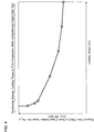
Fig. 4 is a characteristic diagram illustrating engine cranking characteristic showing the relationship of the engine rotation speed with respect to time up to the instance that rotation speed has reached a predetermined speed. -
Fig. 5 is a diagram for describing the manner to determine possible motor output torque (rated torque) according to the motor/generation inFig. 1 . -
Fig. 6 is a diagram illustrating an available driving force or torque for EV running of the motor/generator out of the possible motor output torque (rated torque) illustrated inFig. 5 with the required driving force on the premise that the cranking torque is at initial value (maximum value). -
Fig. 7 is an explanatory diagram showing a cranking torque control region or range in terms of motor output when the cranking torque control according to control program inFig. 2 . -
Fig. 8 is a characteristic diagram showing change in fuel improvement rate achieved by the cranking torque control at engine start as illustrated inFig. 1 . -
Fig. 9 is a flowchart explaining a cranking torque control program depending on an engine stop position, that is performed by the hybrid controller of power train control system inFig. 1 . -
Fig. 10 is an operational time chart illustrating the cranking torque control depending on the engine stop position illustrated inFig.9 . - Selected embodiments of the present invention will now be explained with reference to the drawings. It will be apparent to those skilled in the art from this disclosure that the following descriptions of the embodiments of the present invention are provided for illustration only and not for the purpose of limiting the invention as defined by the appended claims and their equivalents.
- Referring initially to
Fig. 1 , a powertrain for a hybrid vehicle with an engine start control system according to one embodiment of the present invention is schematically shown. This HEV is obtained by doing alterations on a conventional front engine, front wheel drive vehicle (Front wheel drive vehicle) as a base platform. InFig. 1 ,reference 1 denotes an engine as power source, 2FL and 2FR denote left front wheel and right front wheel, respectively, i.e., left and right driving wheels, 3RL, 3RR denotes a left rear wheel and right rear wheel (left right driven wheels) - In the power train of the hybrid vehicle shown in
Fig.1 , as in the conventional front wheel drive vehicles, a V-belt continuous variable transmission (CVT) 4 is positioned in a transverse direction of the vehicle on a side of thetransverse engine 1 to convey a rotation of the engine (i.e.,crank shaft 1a thereof) to an axis 5 for transfer to aninput shaft 4a of CVT 4 via motor/generator (M/G) 6 by operating (M/G) 6 as a power source. - Motor/generator 6 has an annular stator 6a mounted within a housing and a rotor 6b coaxially disposed within stator 6a mounted within a housing and a rotor 6b coaxially disposed within stator 6a with a preset amount of gap, and responsive to the driving condition associated command, motor/generator 6 is intended to function either as an electric motor (electric motive) or as a generator. Motor/generator 6 is placed between the
engine 1 andCVT 4.
Motor/generator 6 has the above mentioned axis connected to and through the center of the rotor 6b and uses this axis 5 as a motor/generator axis. - Between motor / generator 6 and
engine 1, more specifically, between motor/generator axis 5 andengine crankshaft 1a is interposed a first clutch 7 (CL1) such that a connection betweenengine 1 and motor/generator 6 may be selectively releasable.
It should be noted thatfirst clutch 7 is configure to continuously vary the transmission torque capacity (clutch engagement capacity) and, for example, may be composed, for example, by a wet type multi-plate clutch whose transfer torque capacity (clutch capacity) may be changed by continuously controlling a clutch operating oil flow rate and clutch operative pressure by a linear solenoid valve. - Between motor/generator 6 and V belt continuously variable transmission is connected or engaged to each other by a direct connection of motor/generator shaft 5 to
transmission input shaft 4a, and a second clutch 9 (12) is interposed within thetransmission input shaft 4a. V-belt CVT 4 may be of the conventional type in which a torque converter is removed and motor/generator 6 is directly connected totransmission input shaft 4a instead. When thetransmission input shaft 4a is in an engaged state, rotation speed ofinput shaft 4a is changed depending on the reduction ratio corresponding a pulley ratio of the V-belt CVT to output to output shaft 1 b. The rotation ofoutput shaft 4b of V-belt CVT is transmitted to and distributed via differential gear unit (not shown) to left and right front wheels 2FL, 2FR for propulsion of the vehicle.
It should be noted that the V-belt CVT may be replaced by a step automatic transmission. - It should be noted that second clutch 9 (CL2) that is indispensable to a hybrid vehicle for selectively engaging motor/generator 6 with driving wheels 2FL, 2FR may be disposed in a downstream side of the V-
belt CVT 4, instead of being interposed in thetransmission input shaft 4a, as shown inFig. 1 . However,second clutch 9 may change a transmission torque capacity (clutch engagement capacity) continuously as in the case offirst clutch 7. - In the following, description of the running mode of the above-mentioned power train is made with reference to
Figure 1 . In the following, description of the mode selection function of the above-mentioned power train is made with reference toFigure 1 .
In the powertrain shown inFigure 1 , when an electrically driven mode (EV mode) is required in a low-load, low vehicle speed condition including a vehicle start from a vehicle stop state,first clutch 7 is released andsecond clutch 9 is engaged. - Driving the motor / generator 6 in this state, only output rotation from the motor / generator 6 is directed to input
shaft 4a oftransmission 4, which in turn converts the rotation thereto responsive to a pulley ratio under selection and outputs from thetransmission output shaft 4b.
Rotation from thetransmission output shaft 4b will then be transmitted, through a differential gear device (not shown), finally to front wheels 2FL, 2FR. The vehicle can thus travel only by the electric motor / generator 6 (under EV mode). - When a hybrid running operation (HEV mode) is required such as at high speed driving or under a heavy load condition, the
first clutch 7 is engaged and thesecond clutch 9 is engaged.
In this state, both the output rotation from theengine 1 and output speed from motor/generator 6 will be reached totransmission input shaft 4a in a collaborative or coordinated way, and V-belt CVT 4 changes the rotation speed of theinput shaft 4a to output an appropriate speed from theoutput shaft 4b, depending on the pulley ration under selection.
Rotation from thetransmission output shaft 4b will then reach the front wheels, 2FL, 2FR through differential gear unit (not shown) to allow to operate the vehicle by both theengine 1 and motor/generator 6 in a hybrid running operation (HEV running mode). - While driving in the HEV running mode, when a surplus energy is produced by operating the
engine 1 at an optimum fuel consumption, motor/generator 6 will be allowed to operate as a generator for the excess energy to be converted into electricity energy such that the electricity power generated will stored in a battery for future use of the motor/generator 6 for a motor operation to thereby improve fuel efficiency of theengine 1. - The selection of the above described EV mode and HEV mode may be conducted as follows;
When vehicle speed is below a predetermined value (e.g., below 30 km/h), and accelerator opening is less than a predetermined openness (e.g., below 1/8) or change rate of accelerator opening is less that a predetermined acceleration command (e.g.,0.05G), motor/generator speed is less than a predetermined motor speed (e.g., 1000 rpm or less), engine cooling water temperature is more than a predetermined value (e.g., 40 °C or more) and finally battery storage condition, SOC (state of charge) exceeds a preset storage condition (e.g., 60% or more), then an EV mode is commanded and the vehicle is driven solely electrically, i.e., by motor/generator 6 only. - However, if one of the above conditions necessary for EV mode selection should fail, for example,
accelerator opening exceeds the predetermined opening (1/8) during an EV driving state in response to depressing on accelerator pedal, or the change rate in accelerator pedal exceeds the predetermined acceleration command (0.05G) or the battery storage condition SOC falls below the predetermined stored condition (60%), a HEV mode will be commanded for a hybrid (HEV) driving under coordinated operations ofengine 1 with motor/generator 6. - Hereinafter, a control system is described for hybrid vehicle powertrain above described and comprised by
engine 1, the motor / generator 6, first clutch 7 (CL1), and second clutch 9 (CL2) with reference toFigure 1 .
The control system comprises a controller 11 for controlling a hybrid powertrain operating point in a collaborative or coordinated way. Specifically, the operating point of the powertrain may be defined by a target engine torque tTe, a target motor / generator torque tTm, a target engaging capacity offirst clutch 7, tTc1 (first clutch engaging pressure command value tPc1), and a target engaging capacity ofsecond clutch 9, tTc2 (second clutch engaging pressure command value tPc2). - In order to determine an operating point of the above powertrain, the hybrid controller 11 is supplied with a plurality of signals including a signal from engine
rotation speed sensor 12 that detects an engine rotation speed Ne, a signal from motor/generatorrotation speed sensor 13 that detects a rotation speed of motor/generator Nm, a signal from inputrotation speed sensor 14 that detects a rotation speed of the transmission input Ni, a signal of outputrotation speed sensor 15 that detects a transmission output rotation speed No (vehicle speed VSP), a signal of acceleratorpedal openness sensor 16 that detects an accelerator pedal stroke (accelerator opening AP0), a signal fromstorage condition sensor 17 that detects a storage condition or state of charge (SOC) ofbattery 31 for storing electricity power for motor/generator 6, and finally a signal from an enginestop position sensor 18 that detect a crank angle a at whichengine 1 has stopped. - Hybrid controller 11 selects an operation mode (EV mode or HEV mode) that can achieve the driving power the driver desires based on the accelerator opening degree AP0, battery storage condition SOC, and transmission output rotation speed No (i.e., vehicle speed, VSP) among the above referenced information. In addition, the hybrid controller 11 calculates a target engine torque tTe, target motor/generator torque tTm, target first clutch engaging capacity tTc1, and target second clutch engaging capacity tTc2, respectively.
- The target engine torque, tTe is supplied to the
engine controller 32. Thecontroller 32 in turn controlsengine 1 to attain the target engine torque tTe by employing controls such as a throttle opening control and fuel injection quantity control under a prevailing engine speed Ne based on the engine rotation speed Ne detected bysensor 12 and the target engine torque tTe supplied. - The target motor / generator torque tTm is supplied to the
motor controller 33. Themotor controller 33 in turn operates to convert a direct current from thebattery 31 to alternate current byinverter 34, or supplies the inverted current to a stator 6a of motor/generator 6 under the control ofinverter 34 to control motor/generator so that the motor / generator torque matches target motor/generator torque tTm. - When the target motor / generator torque target tTm is determined such as to require a regenerative braking effect on the motor / generator 6, the
motor controller 33 will apply an appropriate amount of load for electricity generation on motor/generator 6 so as not to overcharge in view of the battery charge condition SOC detected bysensor 17 so that electricity generated by motor/generator 6 by the regenerative braking will be converted through aninverter 34 from AC to DC for storage in thehigh voltage battery 31. - The target first clutch engagement capacity tTc1 is supplied to the first
clutch controller 36. The firstclutch controller 36 in turn compares a first clutch engagement pressure command value tPc1 corresponding to the target first clutch engagement capacity tTc1 with an engagement pressure Pc1 of thefirst clutch 7 detected bysensor 19, and performs an engagement capacity control onfirst clutch 7 by controlling the engagement pressure offirst clutch 7 via a first clutch engagementpressure control unit 37 so that the first clutch engagement pressure Pc1 equals to the first clutch engagement pressure command value tPc1. - The target second clutch engagement capacity tTc2 is supplied to the
transmission controller 38. Thetransmission controller 38 in turn compares a second clutch engagement pressure command value tPc2 corresponding to the target second clutch engagement capacity tTc2 with an engagement pressure Pc2 of thesecond clutch 9 detected bysensor 20, and performs an engagement capacity control onsecond clutch 9 by controlling the engagement pressure ofsecond clutch 9 via a second clutch engagementpressure control unit 39 so that the second clutch engagement pressure Pc2 equals to the second clutch engagement pressure command value tPc2. - Note that the
transmission controller 38 seeks the preferred gear ratio from the current gear ratio based on a map prepared using the transmission output rotation speed No detected by the sensor 15 (vehicle speed, VSP) and the accelerator opening APO detected bysensor 16 and causes a speed change from a current pulley ratio to the preferred pulley ratio. - Although the above description is an outline of a normal control performed by the control system in
Figure 1 , in this embodiment, however, a hybrid controller 11 inFigure 1 is employed to perform a learning control program inFigure 2 and adjust a cranking torque Tcr for an engine start control (cranking torque control) according to the present invention. - Note that starting the engine is performed by having clutch 7 (CL1) connected and cranking the
engine 1 by cranking torque Tcr from the motor/generator 6. During this engine starting period, the cranking torque control inFig.2 will be performed. - Initially, in step S10, a determination is made as to whether the vehicle accelerator command reflected in an accelerator pedal manipulation by a drive is small or not based on accelerator opening AP0 and its change rate over time. When the required acceleration is not less than a predetermined acceleration, cranking torque Tcr is reset to an intial value in step S19.
- The initial value of the cranking torque Tcr, should be defined with a maximum required acceleration in mind and set for a such magnitude of cranking torque which enables an increase in engine speed from zero rpm to 1000 rpm within 0.3 seconds so that, even in situations that require the greatest acceleration, engine start is performed in response to the maximum required acceleration so as to increase the driving force of the vehicle without delay of acceleration command. Thus, when a determination is made whether the required acceleration is small in step S10, the decision shall be made depending on whether the required acceleration is less than the predetermined acceleration that is set in the vicinity of the above maximum required acceleration.
- If the required acceleration is determined to be larger than the predetermined acceleration in step S10, in step S19 as described above, the cranking torque Tcr shall be set to the initial value (maximum)
By starting the engine in a responsiveness that corresponds to the great required acceleration near maximum, vehicle driving force will be increased without delay in response to command. - However, if the required acceleration is determined to be small and less than the above referenced predetermined acceleration, as described below, cranking torque Tcr will be adjusted to take a smaller value than the above initial value (maximum value) in steps S11 to S18. In step S11, the measurement of engine start time tMs1 required for start of engine is started. Therefore, step S11 corresponds to an engine start time measurement means according to the present invention.
- However, in the present embodiment, the engine start time TMst is defined to be a time period between engine start commands t1, t3 and t5 in
Fig. 3 (start of cranking) and the instants t2, t4 and t6 inFig. 3 , at which engine rotation speed Ne has reached a predetermined rotation speed Ne_s (i.e, 600 rpm).
By counting time thus explained inFig. 3 , measurement of engine start time TMst is made possible without waiting for a completion of engine start operation. - In the subsequent step S12, check is made whether or not the above described engine start time TMst is below a engine start time limit value (upper limit) TMst_Lim. In other words, a determination is made as to whether the engine start time TMst is excessively short with respect to engine start enabling and permissible time so that a overly high responsiveness in engine is required. It should be noted that the engine start enabling region may be defined to be such a region in which the time required for engine start is within a predetermined time and the engine can climb over a compression TDC (Top Dead Center) position of first occurrence.
- <TMst_Lim (starting response of the engine is too high) is made, in view of the relationship of engine start time TMst with cranking torque Tcr being illustrated in
Fig. 4 , in step S13, as exemplified at instant t2 inFig. 3 , cranking torque Tcr will be adjusted to be reduced by a reduction amount, ΔTcr_dec and the cranking torque Tcr is updated to this adjusted value. - When in step S12, TMst ≧ TMst_Lim (starting response of engine is too low) is determined, based on the relationship illustrated in
Figure 4 for engine start time TMst and cranking torque Tcr, as in step S16 inFig. 3 , the cranking torque Tcr will be adjusted to be increased by an increase amount ΔTcr_inc, and subsequently cranking torque Tcr will be updated t6 this value after adjustment. - Thus, steps S12 to step S14 are intended to adjust cranking torque Tcr to take less value than the initial value (maximum value) and correspond to the cranking torque adjustment means according to the present invention.
- In step S15 which is selected after execution of step S13 or step S14, it is checked as to whether the increase adjustment in cranking torque has just been performed. Unless the adjustment has just been made in increasing cranking torque Tcr, or, put another way, if the decrease adjustment in cranking torque Tcr has immediately been conducted in step S13, in step S16. the decrease amount in cranking torque ΔTcr_ded will be decreased by a predetermined amount, γ, and updated for use in the subsequent decrease adjustment in cranking torque Tcr in step S13.
- Therefore, as appreciated at instants T2, t4 in
Fig. 3 , when determinations in step S12, i.e.,
TMst < TMst_Lim (engine response too high) continues and adjustments of cranking torque Tcr in a decreasing direction reiterates in step S13, each time the cranking torque Tcr is adjusted to decrease (step S13), the decrease amount ΔTcr_dec will be decreased by the predetermined amount γ and used in a subsequent decrease adjustment in cranking torque Tcr in step S13 and control stability will be purported during a repetitive, decrease adjustments of cranking torque Tcr. - However, in step S15, when it is determined in
step 15 that an increase adjustment in cranking torque Tcr (step S14) has just been made, the adjustment amount ΔTcr_dec will be set to an initial value for use in a decrease adjustment of cranking torque Tcr in step S13 subsequently executed. - In step S18 which is selected after execution of step S17 or step S17, a check is made for occurrence of a phenomenon with an engine friction increase. The increase at engine start in an engine friction is intended to specify a situation in which engine coolant temperature lies at a temperature prior to warming-up, or a failure in engine control system, or other phenomena which deteriorate engine start up property.
- Without the phenomena associated with engine friction increase, control returns back step S10 and the above described learning control of the cranking torque Tcr may be repeated. However, such a phenomenon with increase in engine friction cranking torque is not present, control may return to step S10 and the lerning control of cranking torque Tcr may be repeated. However, if the phenomena associated with engine friction increase are experienced at engine start, then the above adjustments in cranking torque Tcr might be inappropriate and inconsistent with reality with a risk of the inability to start the engine, cranking torque Tcr may be reset to initial value (maximum).
- Incidentally, in case that the required acceleration is determined to be small in step S10, in step S11 to step S18, the reason for setting cranking torque Tcr to be less than the above described initial value (maximum value) is because of avoiding the occurrence of the problems below due to the excessive magnitude of cranking torque Tcr with respect to required acceleration while in situations in which required accelerations are small and when employing the initial value (maximum value) of the cranking torque Tcr would be used over entire driving regions.
- However, to enable motor/generator 6 to start an engine, possible motor output torque (rated torque) of motor/generator 6 that is subject to change as illustrated in
Fig.5 with respect to a vehicle speed VSP (motor/generator rotation speed Nm) has a sufficient amount or magnitude that needs to meet a sum of the torque for EV running including both a driving torque portion corresponding to the vehicle running resistance (such as air resistance and rolling resistance) and an acceleration torque margin corresponding a predetermined acceleration margin, and a cranking torque Tr. - Incidentally, it is generally desirable to keep the rated torque small , and thus the motor/generator as compact as possible in terms of installation space and cost point of view so that the amount of rated torque may be restricted.
- On the other hand, however, while the possible output torque (rateed torque) is restricted, there is a limit in downsizing since the required acceleration margin is generally prefixed and difficult to be excessively reduced.
In addition, when keeping the cranking torque portion Tcr to take an initial value (maximum value) corresponding to the maximum required driving force as explained above even in situations of small required driving force, the cranking torque portion Tcr becomes excessive, and the driving force which is obtained by deducing a sum of the acceleration torque margin and cranking torque portion Tcr from the motor/generator rated torque will be uselessly small by the excessive amount of the initial value of the cranking torque (maximum value). - When the driving torque portion is reduced this way, because of a lack of torque, the situation might occur earlier, i.e., even at a low vehicle speed, at which a vehicle running under EV mode is not possible and thus the mode has to be switched to the HEV mode earlier, i.e., from a low vehicle speed, in which the vehicle will be driven through cooperation with the engine and motor/generator. This entails a narrow region of EV mode originally intended for improved fuel consumption effect and resulting in a problem of worsening the vehicle fuel efficiency.
- For additional explanations on the basis of
Figure 6 , reference is made toFigure 6 where a possible maximum driving force output of motor is shown by a broken line, that is the driving force equivalent to the possible motor output torque (rated torque) inFig. 5 . Also, the driving force for EV running (driving force equivalent to the EV running torque portion inFig. 5 ) which is obtainable by subtracting the driving force corresponding to the initial value (maximum value) of cranking torque portion Tcr inFig. 5 from the possible motor output driving force is indicated by a chain dashed line. A practically available driving force for EV running (a driving force equivalent to the torque portion for EV running inFig. 5 ) which is obtainable by subtracting a driving force for acceleration torque margin corresponding to the acceleration torque margin, which is a driving force equivalent to the acceleration torque margin portion inFig.5 , from the EV running driving force is shown in a double-dashed line. Finally, an EV running required driving force (the aforementioned running resistance) is indicated by a solid line. - If the initial value (maximum value) of cranking torque Tcr is used over the entire operating regions, in situations requiring a small acceleration, the driving force due to the initial value (maximum value) of the cranking torque portion Tcr becomes larger than necessary, and hence the practically available driving force for EV running will be restricted smaller about the excessive amount, as shown in the Figure.
- Therefore, during the EV running, immediately upon reaching a relatively lower vehicle speed VSP_s, the practically available driving force for EV running (double-dashed line) to be used for EV running may fall below the EV running required driving force (solid line) and thus the EV running by way of motor/generator 6 only will not be possible due to a lack in driving force of motor/generator 6. Therefore, when the vehicle speed VSP meets the expression, VSP ≧ VSP_s, a switch to a HEV running mode have to be compelled under collaboration of
engine 1. Thus, the EV mode region in which a fuel consumption is purported to be improved will be small and restricted to the region indicated by VSP < VSP_s shown inFig.6 .with a result of deteriorated fuel efficiency. - Incidentally, in the present embodiment, when the required acceleration is determined to be large (step S10), although cranking torque Tcr will be set to the above mentioned initial value (maximum value) in step S19, when the required acceleration is small (step S10), cranking torque Tcr is adjusted to a smaller value such that an engine start time TMst may be set to an engine start enabling and permissible limit value TMst_Lim and cranking torque Tcr will not exceed the required driving force (see step S11 to setp S18). Therefore, when the practically available driving force may be adjusted to increase about the above explained decrease amount of cranking torque Tcr for situations requiring a small acceleration.
- Therefore, when the required acceleration is small, the vehicle speed VSP_s at which the practically available driving force during EV running falls below the EV running required driving force and, due to a lack in driving torque of motor/generator 6, the EV running by way of motor/generator 6 only will not be feasible, may be shifted from the vehicle speed value shown in
Fig. 6 in a high speed direction with a result that a fuel economy may be improved by an expanded region of EV mode for fuel efficiency improvement purpose and resolution of the above referenced problem of fuel economy deterioration. - By referring to
Fig. 7 , the decrease adjustment range (control range) of cranking torque Tcr from the initial value (maximum value) is now described in connection with a motor output basis of motor/generator 6. InFig. 7 , the maximum motor output from motor/generator 6 is shown in a broken line. Also, when the cranking torque Tcr is at initial value (maximum value), the initial motor output of motor/generator available for EV running may be obtainable by deducing a motor output equivalent to the initial cranking torque (maximum value) from the maximum motor output (broken line) and is represented in a double-dashed line - Therefore, the control range of cranking torque Tcr shall be depicted on a motor output basis of motor/generator 6 as is shown between the double-dashed line and a single-dashed line. Here, when the required acceleration is small, the motor output available for EV running out of motor/generator is increased from a level specified by the double-dashed line in
Fig.7 to a level specified by the single-dashed line so that, by just as much as the increased amount in motor output for EV running, the upper limit vehicle speed for EV running will be raised, and the mode switching to HEV mode will be postponed.
Therefore, the EV mode range for improvement of fuel efficiency may be expanded to a higher vehicle speed region and corresponding to the expanded region of EV mode, vehicle fuel economy will be improved as shown inFig. 8 . - Although cranking torque Tcr is basically controlled as above described, the easiness with which the engine may be restarted (engine start up property) may vary depending on its stop position (crank angle ast). Thus, in the present embodiment, cranking torque Tcr is also made subject to change based on the engine stop position (crank angle ast).
- To this aim, the hybrid controller 11 in
Fig. 1 performs a control program inFig. 9 and, as shown inFig. 10 , makes an adjustment in cranking torque Tcr in accordance with an engine stop position (crank angle ast).
In step S21, a check is made whether or not engine has stopped, if engine has not yet stopped, control exits, whileengine 1 has come to stop, control proceeds to step S22 in which adjustment in cranking torque Tcr is made in accordance with an engine stop position (crank angle ast). - More specifically, in step S22, when the
engine 1 is confirmed to be stopped (at the instant t1 inFig.10 ), engine crank angle reading a is set to be that of a engine stop position (i.e., crank angle ast). When the engine stop position (crank angle ast) represents that of an easier engine restart property, then as showin inFig.10 , cranking torque Tcr may be decreased by ΔTcr_a corresponding a high restart property. On the other hand, when the engine stop position (crank angle ast) is that of a low engine restart property, then cranking torque Tcr will be increased to compensate for the low start up property. - Therefore, step S22 corresponds to the engine stop position detecting means and cranking torque adjustment means according to the present invention.
- According to the engine start control (cranking torque adjustment) in the above described embodiments, although for a large required acceleration (at step S10) cranking torque Tcr is set to be an initial value (maximum value) at step S14, when the required acceleration is small (step S10), cranking torque Tcr will be adjusted to be decreased and take a value smaller than the initial value (maximum value) in such a way that engine start time TMst is a engine start enabling, permissible limit value TMst_Lim with a result that cranking torque Tcr will not be excessively large as compared to the required driving force (at step S11 to step S18), at a small required acceleration, the practically available driving force for EV running in
Fig. 6 may be expanded about the decrease amount in cranking torque Tcr. - In addition, since the limit value TMst_Lim is set to be a engine start enabling and permissible or acceptable critical value associated with an engine start time, the lower limit value of cranking torque Tcr corresponds the engine start enabling and permissible lower limit of cranking angle so that the above effects may be achieved without causing an engine to be disabled to start. or inconvenience of prolonged starting time.
- Moreover, in the present embodiment, the time between the initiation or start of cranking (t1, t3, t5 in
Fig.1 ) and the instant (t2, t4, and t6, inFig.3 ) at which engine rotation speed Ne reached a predetermined rotation speed Ne_s is measured as an engine start time TMst and employed, measurement of engine start time TMst is available without waiting for completion of engine start operation so that responsiveness of control will be improved. - Still further, as described above in reference to
Figs. 9 and10 , when the engine stop position (crank angle ast) is at that which represents a high engine start property, cranking torque Tcr will be decreased in view of the high start property, while, when the engine stop position (crank angle position ast) is at a low engine restart property, cranking torque will be accordingly increased to compensate for the lower engine start property, an appropriate adjustment in cranking torque Tcr is made in accordance with the engine stop position (crank angle ast) closely related to the easiness of engine restart so that cranking torque may be adjusted to an appropriate value, nether too large nor too small, to further ensure the above referenced effects.. - In the illustrated embodiment, the limit value for engine start time TMst_Lim in step S12 in
Fig 2 is defined as such a limit value that enables engine start and yet acceptable for engine start time. However, this limit value TMs_Lim may be substituted for a limit value for enabling engine start with a required responsiveness depending on the respective required accelerations. - In this case, in step S12, a check is made whether or not the engine start time TMst is excessively short for the required engine start responsiveness corresponding to the respective required acceleration, and the engine start responsiveness is too high for the requested acceleration. When the engine start responsiveness is too high for the required acceleration, cranking torque Tcr will be adjusted to be decreased in step S13, and when the engine start responsiveness is too low for the required acceleration cranking torque Tcr is adjusted to be increased in step S14.
- Therefore, as the required acceleration decreases, motor output for EV running of motor/generator 6 available for EV running will be continuously increased from the level specified by double-dashed line in
Fig. 7 to that of single-dashed line, and EV running (EV mode) region will be continuously expanded with the decrease of the required acceleration, , which allows more precise control according to the required acceleration. -
- 1
- Engine
- 2FL, 2FR
- Left and right front wheels (driving wheels).
- 3RL, 3RR
- Left and right rear wheels
- 4
- V-belt continuously variable transmission (CVT)
- 6
- Motor / Generator
- 7
- First clutch
- 9
- Second clutch
- 11
- Hybrid controller
- 12
- Engine rotation speed sensor
- 13
- Motor/generator rotation speed sensor
- 14
- Transmission input speed sensor
- 15
- Transmission output speed sensor
- 16
- Accelerator opening sensor
- 17
- Storage condition sensor
- 18
- Engine crank angle sensor
- 31
- Battery
- 32
- Engine controller
- 33
- Motor controller
- 34
- Inverter
- 36
- First clutch controller
- 37
- First clutch engagement pressure control unit
- 38
- Transmission controller
- 39
- Second clutch engagement pressure control unit
Claims (8)
- An engine start control system for a hybrid electric vehicle having a power train comprised of an engine, a first clutch, a motor/generator, a second clutch and driving wheels as the torque transmission path arranged in these order, the vehicle being operable in two driving modes by selectively controlling an engagement or release of the first and second clutches so that the vehicle may be either electrically driven by the motor/generator only, or may be driven by both the engine and the motor/generator under a hybrid mode, and further operable to start the engine by a cranking torque from the motor/generator in response to engagement of the first clutch, characterized in that the engine start control system further includes a cranking torque adjustment means to adjust the cranking torque to be decreased when the required vehicle acceleration is small.
- The engine start control system for the hybrid electric vehicle as claimed in claim 1, wherein the lower limit of the cranking torque to be adjusted by the cranking torque adjustment means is defined to a lower limit for the engine torque that enables an engine start.
- The engine start control system for the hybrid electric vehicle as claimed in claim 2, wherein the cranking torque adjustment means defines a lower limit of engine torque that enables an engine start in response to a respective required acceleration.
- The engine start control system for the hybrid electric vehicle as claimed in any of claims 1 to 3, further including an engine start time measurement means measuring an engine start time required for an engine start, and the cranking torque adjustment means is configured to adjust the cranking torque so that the measured engine start time matches a predetermined time.
- The engine start control system for the hybrid electric vehicle as claimed in claim 4, the predetermined time involved in the engine start time is a limit value for an engine start time that is capable of starting the engine.
- The engine start control system for the hybrid electric vehicle as claimed in claim 5, the predetermined time involved in the engine start time is respective limit values which is capable of starting the engine in a required responsiveness according to the required respective accelerations.
- The engine start control system for the hybrid electric vehicle as claimed in any one of claim 4 to claim 6, the engine start time measurement means measures a time from the cranking starting instant through the instant at which the engine rotation speed reaches a predetermined rotation speed.
- The engine start control system for the hybrid electric vehicle as claimed in any one of claims 1 to 7, further comprising an engine stop position detecting means, and wherein the cranking torque adjustment means is configured to adjust the cranking torque in accordance with the detected engine stop position.
Applications Claiming Priority (1)
| Application Number | Priority Date | Filing Date | Title |
|---|---|---|---|
| JP2011112159A JP5899657B2 (en) | 2011-05-19 | 2011-05-19 | Engine start control device for hybrid vehicle |
Publications (3)
| Publication Number | Publication Date |
|---|---|
| EP2525078A2 true EP2525078A2 (en) | 2012-11-21 |
| EP2525078A3 EP2525078A3 (en) | 2016-12-07 |
| EP2525078B1 EP2525078B1 (en) | 2019-12-18 |
Family
ID=45876554
Family Applications (1)
| Application Number | Title | Priority Date | Filing Date |
|---|---|---|---|
| EP12001435.2A Active EP2525078B1 (en) | 2011-05-19 | 2012-03-02 | Engine start control system for hybrid electric vehicle |
Country Status (4)
| Country | Link |
|---|---|
| US (1) | US8531051B2 (en) |
| EP (1) | EP2525078B1 (en) |
| JP (1) | JP5899657B2 (en) |
| CN (1) | CN102785658B (en) |
Cited By (1)
| Publication number | Priority date | Publication date | Assignee | Title |
|---|---|---|---|---|
| EP3785964A1 (en) * | 2019-08-29 | 2021-03-03 | Mazda Motor Corporation | Hybrid vehicle control system |
Families Citing this family (22)
| Publication number | Priority date | Publication date | Assignee | Title |
|---|---|---|---|---|
| KR101294054B1 (en) * | 2011-06-01 | 2013-08-07 | 현대자동차주식회사 | Fuel cut mehod of hybrid vehicle |
| JP5962463B2 (en) * | 2012-11-27 | 2016-08-03 | 三菱自動車工業株式会社 | Engine start determination device |
| BR112015017522B1 (en) * | 2013-01-22 | 2021-02-23 | Toyota Jidosha Kabushiki Kaisha | control device for a hybrid vehicle |
| US9499159B2 (en) * | 2013-08-19 | 2016-11-22 | Denso Corporation | Vehicle control apparatus |
| JP2015085808A (en) * | 2013-10-30 | 2015-05-07 | 株式会社デンソー | Control device for hybrid vehicle |
| JP6020522B2 (en) * | 2014-07-22 | 2016-11-02 | トヨタ自動車株式会社 | Hybrid car |
| US9656666B2 (en) * | 2014-08-28 | 2017-05-23 | Ford Global Technologies, Llc | Methods and systems for starting an engine |
| US9950705B2 (en) * | 2015-07-17 | 2018-04-24 | Ford Global Technologies, Llc | Hybrid vehicle and method of controlling an engine disconnect clutch for engine start-up |
| US10106053B2 (en) * | 2016-03-31 | 2018-10-23 | Honda Motor Co., Ltd. | Vehicle |
| US9932031B2 (en) * | 2016-05-10 | 2018-04-03 | Ford Global Technologies, Llc | System and method for hybrid vehicle engine starts |
| US10106162B2 (en) * | 2016-07-19 | 2018-10-23 | Ford Global Technologies, Llc | Methods and system for starting an engine |
| FR3060499B1 (en) * | 2016-12-16 | 2020-09-25 | Continental Automotive France | PROCESS FOR MANAGING A TRANSITIONAL PHASE OF STARTING A THERMAL MOTOR BY AN ELECTRIC MACHINE |
| US10272907B2 (en) * | 2017-01-23 | 2019-04-30 | Ford Global Technologies, Llc | System and method for fast engine starts with belt integrated starter generator assist during locking of disconnect clutch |
| JP7023572B2 (en) * | 2018-01-31 | 2022-02-22 | ダイハツ工業株式会社 | Hybrid car |
| DE102018110859B4 (en) * | 2018-05-07 | 2020-03-19 | Schaeffler Technologies AG & Co. KG | Method for restarting an internal combustion engine in a hybrid powertrain |
| JP2020040614A (en) * | 2018-09-13 | 2020-03-19 | マツダ株式会社 | Engine start control device for hybrid vehicle |
| DE102019124922A1 (en) * | 2019-09-17 | 2021-03-18 | Bayerische Motoren Werke Aktiengesellschaft | Control unit and method for operating an electric machine of a hybrid drive |
| CN110985260B (en) * | 2019-11-25 | 2021-11-05 | 山东元齐新动力科技有限公司 | Range extender starting control method and equipment, range extender electric vehicle and storage medium |
| US11345326B2 (en) | 2020-03-25 | 2022-05-31 | Ford Global Technologies, Llc | Methods and system for starting an internal combustion engine |
| US11623631B2 (en) * | 2020-06-02 | 2023-04-11 | Toyota Motor Engineering & Manufacturing North America, Inc. | Control of hybrid vehicle engine start threshold in congested traffic conditions |
| CN116472211A (en) * | 2020-11-06 | 2023-07-21 | 舍弗勒技术股份两合公司 | Engine start control method and device for hybrid electric vehicle |
| CN113147721B (en) * | 2021-05-27 | 2023-03-07 | 中国第一汽车股份有限公司 | Method and device for controlling engine starting, electronic equipment and storage medium |
Citations (1)
| Publication number | Priority date | Publication date | Assignee | Title |
|---|---|---|---|---|
| JP2010179865A (en) | 2009-02-09 | 2010-08-19 | Nissan Motor Co Ltd | Controller for hybrid vehicle |
Family Cites Families (19)
| Publication number | Priority date | Publication date | Assignee | Title |
|---|---|---|---|---|
| DE2133485A1 (en) * | 1971-07-06 | 1973-01-25 | Bosch Gmbh Robert | MOTOR VEHICLE WITH A HYBRID DRIVE |
| JPS5823250A (en) * | 1981-07-31 | 1983-02-10 | Toyota Motor Corp | Control method of automatic engine stop/restart |
| JP2765840B2 (en) * | 1987-10-07 | 1998-06-18 | アイシン・エィ・ダブリュ株式会社 | Power transmission device for hybrid vehicle |
| JP3775012B2 (en) * | 1997-08-29 | 2006-05-17 | アイシン・エィ・ダブリュ株式会社 | Hybrid drive device for vehicle |
| JP3379439B2 (en) * | 1997-09-17 | 2003-02-24 | トヨタ自動車株式会社 | Start control device for internal combustion engine |
| JP3454245B2 (en) * | 2000-10-26 | 2003-10-06 | トヨタ自動車株式会社 | Vehicle start control device |
| JP2004036429A (en) * | 2002-07-01 | 2004-02-05 | Toyota Motor Corp | Control device for internal combustion engine |
| DE102004037584B4 (en) * | 2004-08-03 | 2008-05-08 | Bayerische Motoren Werke Ag | Method for operating a drive unit |
| US7220217B2 (en) * | 2005-01-26 | 2007-05-22 | General Motors Corporation | Engine spin-up control with natural torque smoothing |
| FR2892471B1 (en) * | 2005-10-20 | 2008-02-15 | Peugeot Citroen Automobiles Sa | METHOD FOR STARTING A THERMAL MOTOR OF A HYBRID VEHICLE |
| JP4640236B2 (en) * | 2006-04-05 | 2011-03-02 | 日産自動車株式会社 | Starter for internal combustion engine |
| JP4816291B2 (en) * | 2006-07-05 | 2011-11-16 | 日産自動車株式会社 | Motor lock prevention device for hybrid vehicle |
| DE102006034937A1 (en) * | 2006-07-28 | 2008-01-31 | Dr.Ing.H.C. F. Porsche Ag | Operating method for a hybrid drive |
| JP2008179283A (en) * | 2007-01-25 | 2008-08-07 | Nissan Motor Co Ltd | Hybrid vehicle mode switching control device |
| DE102007055828A1 (en) * | 2007-12-17 | 2009-06-18 | Zf Friedrichshafen Ag | Method and device for operating a hybrid vehicle |
| US8261864B2 (en) * | 2008-06-17 | 2012-09-11 | GM Global Technology Operations LLC | Hybrid powertrain auto start control system with engine pulse cancellation |
| JP4631962B2 (en) * | 2008-11-11 | 2011-02-16 | トヨタ自動車株式会社 | Engine start control device |
| DE102008064291A1 (en) * | 2008-12-20 | 2010-07-15 | Volkswagen Ag | Vehicle i.e. hybrid vehicle, has electrical machine indirectly connected with transmission, where electrical machine and internal-combustion engine are connected by separation clutch i.e. dosed proportional clutch, in detachable manner |
| CN101898504A (en) * | 2010-08-06 | 2010-12-01 | 上海交通大学 | Dual Clutch Motor Suspension Parallel Hybrid Drive System |
-
2011
- 2011-05-19 JP JP2011112159A patent/JP5899657B2/en not_active Expired - Fee Related
-
2012
- 2012-03-01 US US13/409,658 patent/US8531051B2/en not_active Expired - Fee Related
- 2012-03-02 CN CN201210053118.1A patent/CN102785658B/en not_active Expired - Fee Related
- 2012-03-02 EP EP12001435.2A patent/EP2525078B1/en active Active
Patent Citations (1)
| Publication number | Priority date | Publication date | Assignee | Title |
|---|---|---|---|---|
| JP2010179865A (en) | 2009-02-09 | 2010-08-19 | Nissan Motor Co Ltd | Controller for hybrid vehicle |
Cited By (2)
| Publication number | Priority date | Publication date | Assignee | Title |
|---|---|---|---|---|
| EP3785964A1 (en) * | 2019-08-29 | 2021-03-03 | Mazda Motor Corporation | Hybrid vehicle control system |
| US11518365B2 (en) | 2019-08-29 | 2022-12-06 | Mazda Motor Corporation | Hybrid vehicle control system |
Also Published As
| Publication number | Publication date |
|---|---|
| CN102785658B (en) | 2016-04-06 |
| CN102785658A (en) | 2012-11-21 |
| EP2525078B1 (en) | 2019-12-18 |
| EP2525078A3 (en) | 2016-12-07 |
| JP2012240544A (en) | 2012-12-10 |
| US8531051B2 (en) | 2013-09-10 |
| JP5899657B2 (en) | 2016-04-06 |
| US20120292919A1 (en) | 2012-11-22 |
Similar Documents
| Publication | Publication Date | Title |
|---|---|---|
| EP2525078B1 (en) | Engine start control system for hybrid electric vehicle | |
| US8140205B2 (en) | Driving system for hybrid vehicle | |
| EP2532549B1 (en) | Engine start control device for hybrid vehicle | |
| EP1939059B1 (en) | Mode changeover control device for a hybrid vehicle | |
| KR101703613B1 (en) | Method and device for controlling start time of engine in hybrid vehicle | |
| KR101453252B1 (en) | Control device | |
| CN104773161B (en) | Hybrid electric vehicle | |
| EP2783934B1 (en) | Hybrid vehicle control device | |
| CN101209711B (en) | Mode changeover control device for a hybrid vehicle | |
| US8682544B2 (en) | Vehicle and control method thereof | |
| JP6222400B2 (en) | Vehicle control device for hybrid vehicle | |
| US9724992B2 (en) | Hybrid vehicle | |
| KR20140021220A (en) | System for start control of hybrid electric vehicle and method thereof | |
| KR20130136779A (en) | Learn system for engine clutch delivery torque of green car and method thereof | |
| KR102506763B1 (en) | Vehicle including driving motor and control method thereof | |
| JP7487474B2 (en) | Assist control device | |
| JP2012240566A (en) | Electric travel controller for hybrid vehicle | |
| US11485352B2 (en) | Vehicle control device | |
| JP6019784B2 (en) | Engine stop control device for hybrid vehicle | |
| JP7687285B2 (en) | Vehicle control device | |
| KR20160142727A (en) | Method and device for controlling start time of engine in hybrid vehicle | |
| KR20210028629A (en) | Method and device for controlling start time of engine in hybrid vehicle |
Legal Events
| Date | Code | Title | Description |
|---|---|---|---|
| PUAI | Public reference made under article 153(3) epc to a published international application that has entered the european phase |
Free format text: ORIGINAL CODE: 0009012 |
|
| 17P | Request for examination filed |
Effective date: 20120302 |
|
| AK | Designated contracting states |
Kind code of ref document: A2 Designated state(s): AL AT BE BG CH CY CZ DE DK EE ES FI FR GB GR HR HU IE IS IT LI LT LU LV MC MK MT NL NO PL PT RO RS SE SI SK SM TR |
|
| AX | Request for extension of the european patent |
Extension state: BA ME |
|
| PUAL | Search report despatched |
Free format text: ORIGINAL CODE: 0009013 |
|
| AK | Designated contracting states |
Kind code of ref document: A3 Designated state(s): AL AT BE BG CH CY CZ DE DK EE ES FI FR GB GR HR HU IE IS IT LI LT LU LV MC MK MT NL NO PL PT RO RS SE SI SK SM TR |
|
| AX | Request for extension of the european patent |
Extension state: BA ME |
|
| RIC1 | Information provided on ipc code assigned before grant |
Ipc: B60W 20/00 20160101ALI20161102BHEP Ipc: F02N 15/02 20060101ALI20161102BHEP Ipc: B60K 6/48 20071001ALI20161102BHEP Ipc: B60W 10/08 20060101ALI20161102BHEP Ipc: F02N 11/04 20060101AFI20161102BHEP Ipc: B60W 10/06 20060101ALI20161102BHEP |
|
| STAA | Information on the status of an ep patent application or granted ep patent |
Free format text: STATUS: EXAMINATION IS IN PROGRESS |
|
| 17Q | First examination report despatched |
Effective date: 20180924 |
|
| RIC1 | Information provided on ipc code assigned before grant |
Ipc: B60K 6/48 20071001ALI20161102BHEP Ipc: B60W 10/06 20060101ALI20161102BHEP Ipc: F02N 15/02 20060101ALI20161102BHEP Ipc: F02N 11/04 20060101AFI20161102BHEP Ipc: B60W 20/00 20160101ALI20161102BHEP Ipc: B60W 10/08 20060101ALI20161102BHEP |
|
| GRAP | Despatch of communication of intention to grant a patent |
Free format text: ORIGINAL CODE: EPIDOSNIGR1 |
|
| STAA | Information on the status of an ep patent application or granted ep patent |
Free format text: STATUS: GRANT OF PATENT IS INTENDED |
|
| INTG | Intention to grant announced |
Effective date: 20190730 |
|
| GRAS | Grant fee paid |
Free format text: ORIGINAL CODE: EPIDOSNIGR3 |
|
| GRAA | (expected) grant |
Free format text: ORIGINAL CODE: 0009210 |
|
| STAA | Information on the status of an ep patent application or granted ep patent |
Free format text: STATUS: THE PATENT HAS BEEN GRANTED |
|
| AK | Designated contracting states |
Kind code of ref document: B1 Designated state(s): AL AT BE BG CH CY CZ DE DK EE ES FI FR GB GR HR HU IE IS IT LI LT LU LV MC MK MT NL NO PL PT RO RS SE SI SK SM TR |
|
| REG | Reference to a national code |
Ref country code: GB Ref legal event code: FG4D |
|
| REG | Reference to a national code |
Ref country code: CH Ref legal event code: EP |
|
| REG | Reference to a national code |
Ref country code: IE Ref legal event code: FG4D |
|
| REG | Reference to a national code |
Ref country code: DE Ref legal event code: R096 Ref document number: 602012066493 Country of ref document: DE |
|
| REG | Reference to a national code |
Ref country code: AT Ref legal event code: REF Ref document number: 1214874 Country of ref document: AT Kind code of ref document: T Effective date: 20200115 |
|
| REG | Reference to a national code |
Ref country code: NL Ref legal event code: MP Effective date: 20191218 |
|
| PG25 | Lapsed in a contracting state [announced via postgrant information from national office to epo] |
Ref country code: LT Free format text: LAPSE BECAUSE OF FAILURE TO SUBMIT A TRANSLATION OF THE DESCRIPTION OR TO PAY THE FEE WITHIN THE PRESCRIBED TIME-LIMIT Effective date: 20191218 Ref country code: NO Free format text: LAPSE BECAUSE OF FAILURE TO SUBMIT A TRANSLATION OF THE DESCRIPTION OR TO PAY THE FEE WITHIN THE PRESCRIBED TIME-LIMIT Effective date: 20200318 Ref country code: GR Free format text: LAPSE BECAUSE OF FAILURE TO SUBMIT A TRANSLATION OF THE DESCRIPTION OR TO PAY THE FEE WITHIN THE PRESCRIBED TIME-LIMIT Effective date: 20200319 Ref country code: FI Free format text: LAPSE BECAUSE OF FAILURE TO SUBMIT A TRANSLATION OF THE DESCRIPTION OR TO PAY THE FEE WITHIN THE PRESCRIBED TIME-LIMIT Effective date: 20191218 Ref country code: BG Free format text: LAPSE BECAUSE OF FAILURE TO SUBMIT A TRANSLATION OF THE DESCRIPTION OR TO PAY THE FEE WITHIN THE PRESCRIBED TIME-LIMIT Effective date: 20200318 Ref country code: SE Free format text: LAPSE BECAUSE OF FAILURE TO SUBMIT A TRANSLATION OF THE DESCRIPTION OR TO PAY THE FEE WITHIN THE PRESCRIBED TIME-LIMIT Effective date: 20191218 Ref country code: LV Free format text: LAPSE BECAUSE OF FAILURE TO SUBMIT A TRANSLATION OF THE DESCRIPTION OR TO PAY THE FEE WITHIN THE PRESCRIBED TIME-LIMIT Effective date: 20191218 |
|
| REG | Reference to a national code |
Ref country code: LT Ref legal event code: MG4D |
|
| PG25 | Lapsed in a contracting state [announced via postgrant information from national office to epo] |
Ref country code: HR Free format text: LAPSE BECAUSE OF FAILURE TO SUBMIT A TRANSLATION OF THE DESCRIPTION OR TO PAY THE FEE WITHIN THE PRESCRIBED TIME-LIMIT Effective date: 20191218 Ref country code: RS Free format text: LAPSE BECAUSE OF FAILURE TO SUBMIT A TRANSLATION OF THE DESCRIPTION OR TO PAY THE FEE WITHIN THE PRESCRIBED TIME-LIMIT Effective date: 20191218 |
|
| PG25 | Lapsed in a contracting state [announced via postgrant information from national office to epo] |
Ref country code: AL Free format text: LAPSE BECAUSE OF FAILURE TO SUBMIT A TRANSLATION OF THE DESCRIPTION OR TO PAY THE FEE WITHIN THE PRESCRIBED TIME-LIMIT Effective date: 20191218 |
|
| PG25 | Lapsed in a contracting state [announced via postgrant information from national office to epo] |
Ref country code: PT Free format text: LAPSE BECAUSE OF FAILURE TO SUBMIT A TRANSLATION OF THE DESCRIPTION OR TO PAY THE FEE WITHIN THE PRESCRIBED TIME-LIMIT Effective date: 20200513 Ref country code: CZ Free format text: LAPSE BECAUSE OF FAILURE TO SUBMIT A TRANSLATION OF THE DESCRIPTION OR TO PAY THE FEE WITHIN THE PRESCRIBED TIME-LIMIT Effective date: 20191218 Ref country code: RO Free format text: LAPSE BECAUSE OF FAILURE TO SUBMIT A TRANSLATION OF THE DESCRIPTION OR TO PAY THE FEE WITHIN THE PRESCRIBED TIME-LIMIT Effective date: 20191218 Ref country code: EE Free format text: LAPSE BECAUSE OF FAILURE TO SUBMIT A TRANSLATION OF THE DESCRIPTION OR TO PAY THE FEE WITHIN THE PRESCRIBED TIME-LIMIT Effective date: 20191218 Ref country code: NL Free format text: LAPSE BECAUSE OF FAILURE TO SUBMIT A TRANSLATION OF THE DESCRIPTION OR TO PAY THE FEE WITHIN THE PRESCRIBED TIME-LIMIT Effective date: 20191218 |
|
| PG25 | Lapsed in a contracting state [announced via postgrant information from national office to epo] |
Ref country code: SM Free format text: LAPSE BECAUSE OF FAILURE TO SUBMIT A TRANSLATION OF THE DESCRIPTION OR TO PAY THE FEE WITHIN THE PRESCRIBED TIME-LIMIT Effective date: 20191218 Ref country code: SK Free format text: LAPSE BECAUSE OF FAILURE TO SUBMIT A TRANSLATION OF THE DESCRIPTION OR TO PAY THE FEE WITHIN THE PRESCRIBED TIME-LIMIT Effective date: 20191218 Ref country code: IS Free format text: LAPSE BECAUSE OF FAILURE TO SUBMIT A TRANSLATION OF THE DESCRIPTION OR TO PAY THE FEE WITHIN THE PRESCRIBED TIME-LIMIT Effective date: 20200418 |
|
| REG | Reference to a national code |
Ref country code: DE Ref legal event code: R097 Ref document number: 602012066493 Country of ref document: DE |
|
| REG | Reference to a national code |
Ref country code: AT Ref legal event code: MK05 Ref document number: 1214874 Country of ref document: AT Kind code of ref document: T Effective date: 20191218 |
|
| PLBE | No opposition filed within time limit |
Free format text: ORIGINAL CODE: 0009261 |
|
| STAA | Information on the status of an ep patent application or granted ep patent |
Free format text: STATUS: NO OPPOSITION FILED WITHIN TIME LIMIT |
|
| PG25 | Lapsed in a contracting state [announced via postgrant information from national office to epo] |
Ref country code: DK Free format text: LAPSE BECAUSE OF FAILURE TO SUBMIT A TRANSLATION OF THE DESCRIPTION OR TO PAY THE FEE WITHIN THE PRESCRIBED TIME-LIMIT Effective date: 20191218 Ref country code: MC Free format text: LAPSE BECAUSE OF FAILURE TO SUBMIT A TRANSLATION OF THE DESCRIPTION OR TO PAY THE FEE WITHIN THE PRESCRIBED TIME-LIMIT Effective date: 20191218 Ref country code: ES Free format text: LAPSE BECAUSE OF FAILURE TO SUBMIT A TRANSLATION OF THE DESCRIPTION OR TO PAY THE FEE WITHIN THE PRESCRIBED TIME-LIMIT Effective date: 20191218 |
|
| REG | Reference to a national code |
Ref country code: CH Ref legal event code: PL |
|
| 26N | No opposition filed |
Effective date: 20200921 |
|
| PG25 | Lapsed in a contracting state [announced via postgrant information from national office to epo] |
Ref country code: AT Free format text: LAPSE BECAUSE OF FAILURE TO SUBMIT A TRANSLATION OF THE DESCRIPTION OR TO PAY THE FEE WITHIN THE PRESCRIBED TIME-LIMIT Effective date: 20191218 Ref country code: SI Free format text: LAPSE BECAUSE OF FAILURE TO SUBMIT A TRANSLATION OF THE DESCRIPTION OR TO PAY THE FEE WITHIN THE PRESCRIBED TIME-LIMIT Effective date: 20191218 |
|
| REG | Reference to a national code |
Ref country code: BE Ref legal event code: MM Effective date: 20200331 |
|
| PG25 | Lapsed in a contracting state [announced via postgrant information from national office to epo] |
Ref country code: LU Free format text: LAPSE BECAUSE OF NON-PAYMENT OF DUE FEES Effective date: 20200302 |
|
| PG25 | Lapsed in a contracting state [announced via postgrant information from national office to epo] |
Ref country code: IE Free format text: LAPSE BECAUSE OF NON-PAYMENT OF DUE FEES Effective date: 20200302 Ref country code: IT Free format text: LAPSE BECAUSE OF FAILURE TO SUBMIT A TRANSLATION OF THE DESCRIPTION OR TO PAY THE FEE WITHIN THE PRESCRIBED TIME-LIMIT Effective date: 20191218 Ref country code: LI Free format text: LAPSE BECAUSE OF NON-PAYMENT OF DUE FEES Effective date: 20200331 Ref country code: CH Free format text: LAPSE BECAUSE OF NON-PAYMENT OF DUE FEES Effective date: 20200331 |
|
| PG25 | Lapsed in a contracting state [announced via postgrant information from national office to epo] |
Ref country code: PL Free format text: LAPSE BECAUSE OF FAILURE TO SUBMIT A TRANSLATION OF THE DESCRIPTION OR TO PAY THE FEE WITHIN THE PRESCRIBED TIME-LIMIT Effective date: 20191218 Ref country code: BE Free format text: LAPSE BECAUSE OF NON-PAYMENT OF DUE FEES Effective date: 20200331 |
|
| PGFP | Annual fee paid to national office [announced via postgrant information from national office to epo] |
Ref country code: GB Payment date: 20220106 Year of fee payment: 11 Ref country code: DE Payment date: 20220105 Year of fee payment: 11 |
|
| PG25 | Lapsed in a contracting state [announced via postgrant information from national office to epo] |
Ref country code: TR Free format text: LAPSE BECAUSE OF FAILURE TO SUBMIT A TRANSLATION OF THE DESCRIPTION OR TO PAY THE FEE WITHIN THE PRESCRIBED TIME-LIMIT Effective date: 20191218 Ref country code: MT Free format text: LAPSE BECAUSE OF FAILURE TO SUBMIT A TRANSLATION OF THE DESCRIPTION OR TO PAY THE FEE WITHIN THE PRESCRIBED TIME-LIMIT Effective date: 20191218 Ref country code: CY Free format text: LAPSE BECAUSE OF FAILURE TO SUBMIT A TRANSLATION OF THE DESCRIPTION OR TO PAY THE FEE WITHIN THE PRESCRIBED TIME-LIMIT Effective date: 20191218 |
|
| PGFP | Annual fee paid to national office [announced via postgrant information from national office to epo] |
Ref country code: FR Payment date: 20220118 Year of fee payment: 11 |
|
| PG25 | Lapsed in a contracting state [announced via postgrant information from national office to epo] |
Ref country code: MK Free format text: LAPSE BECAUSE OF FAILURE TO SUBMIT A TRANSLATION OF THE DESCRIPTION OR TO PAY THE FEE WITHIN THE PRESCRIBED TIME-LIMIT Effective date: 20191218 |
|
| REG | Reference to a national code |
Ref country code: DE Ref legal event code: R119 Ref document number: 602012066493 Country of ref document: DE |
|
| GBPC | Gb: european patent ceased through non-payment of renewal fee |
Effective date: 20230302 |
|
| PG25 | Lapsed in a contracting state [announced via postgrant information from national office to epo] |
Ref country code: GB Free format text: LAPSE BECAUSE OF NON-PAYMENT OF DUE FEES Effective date: 20230302 |
|
| PG25 | Lapsed in a contracting state [announced via postgrant information from national office to epo] |
Ref country code: GB Free format text: LAPSE BECAUSE OF NON-PAYMENT OF DUE FEES Effective date: 20230302 Ref country code: FR Free format text: LAPSE BECAUSE OF NON-PAYMENT OF DUE FEES Effective date: 20230331 Ref country code: DE Free format text: LAPSE BECAUSE OF NON-PAYMENT OF DUE FEES Effective date: 20231003 |