JP6020522B2 - Hybrid car - Google Patents
Hybrid car Download PDFInfo
- Publication number
- JP6020522B2 JP6020522B2 JP2014148931A JP2014148931A JP6020522B2 JP 6020522 B2 JP6020522 B2 JP 6020522B2 JP 2014148931 A JP2014148931 A JP 2014148931A JP 2014148931 A JP2014148931 A JP 2014148931A JP 6020522 B2 JP6020522 B2 JP 6020522B2
- Authority
- JP
- Japan
- Prior art keywords
- engine
- speed
- gear
- resonance
- gear ratio
- Prior art date
- Legal status (The legal status is an assumption and is not a legal conclusion. Google has not performed a legal analysis and makes no representation as to the accuracy of the status listed.)
- Expired - Fee Related
Links
Images


Classifications
-
- B—PERFORMING OPERATIONS; TRANSPORTING
- B60—VEHICLES IN GENERAL
- B60W—CONJOINT CONTROL OF VEHICLE SUB-UNITS OF DIFFERENT TYPE OR DIFFERENT FUNCTION; CONTROL SYSTEMS SPECIALLY ADAPTED FOR HYBRID VEHICLES; ROAD VEHICLE DRIVE CONTROL SYSTEMS FOR PURPOSES NOT RELATED TO THE CONTROL OF A PARTICULAR SUB-UNIT
- B60W20/00—Control systems specially adapted for hybrid vehicles
- B60W20/10—Controlling the power contribution of each of the prime movers to meet required power demand
-
- B—PERFORMING OPERATIONS; TRANSPORTING
- B60—VEHICLES IN GENERAL
- B60K—ARRANGEMENT OR MOUNTING OF PROPULSION UNITS OR OF TRANSMISSIONS IN VEHICLES; ARRANGEMENT OR MOUNTING OF PLURAL DIVERSE PRIME-MOVERS IN VEHICLES; AUXILIARY DRIVES FOR VEHICLES; INSTRUMENTATION OR DASHBOARDS FOR VEHICLES; ARRANGEMENTS IN CONNECTION WITH COOLING, AIR INTAKE, GAS EXHAUST OR FUEL SUPPLY OF PROPULSION UNITS IN VEHICLES
- B60K6/00—Arrangement or mounting of plural diverse prime-movers for mutual or common propulsion, e.g. hybrid propulsion systems comprising electric motors and internal combustion engines
- B60K6/20—Arrangement or mounting of plural diverse prime-movers for mutual or common propulsion, e.g. hybrid propulsion systems comprising electric motors and internal combustion engines the prime-movers consisting of electric motors and internal combustion engines, e.g. HEVs
- B60K6/22—Arrangement or mounting of plural diverse prime-movers for mutual or common propulsion, e.g. hybrid propulsion systems comprising electric motors and internal combustion engines the prime-movers consisting of electric motors and internal combustion engines, e.g. HEVs characterised by apparatus, components or means specially adapted for HEVs
- B60K6/36—Arrangement or mounting of plural diverse prime-movers for mutual or common propulsion, e.g. hybrid propulsion systems comprising electric motors and internal combustion engines the prime-movers consisting of electric motors and internal combustion engines, e.g. HEVs characterised by apparatus, components or means specially adapted for HEVs characterised by the transmission gearings
- B60K6/365—Arrangement or mounting of plural diverse prime-movers for mutual or common propulsion, e.g. hybrid propulsion systems comprising electric motors and internal combustion engines the prime-movers consisting of electric motors and internal combustion engines, e.g. HEVs characterised by apparatus, components or means specially adapted for HEVs characterised by the transmission gearings with the gears having orbital motion
-
- B—PERFORMING OPERATIONS; TRANSPORTING
- B60—VEHICLES IN GENERAL
- B60K—ARRANGEMENT OR MOUNTING OF PROPULSION UNITS OR OF TRANSMISSIONS IN VEHICLES; ARRANGEMENT OR MOUNTING OF PLURAL DIVERSE PRIME-MOVERS IN VEHICLES; AUXILIARY DRIVES FOR VEHICLES; INSTRUMENTATION OR DASHBOARDS FOR VEHICLES; ARRANGEMENTS IN CONNECTION WITH COOLING, AIR INTAKE, GAS EXHAUST OR FUEL SUPPLY OF PROPULSION UNITS IN VEHICLES
- B60K6/00—Arrangement or mounting of plural diverse prime-movers for mutual or common propulsion, e.g. hybrid propulsion systems comprising electric motors and internal combustion engines
- B60K6/20—Arrangement or mounting of plural diverse prime-movers for mutual or common propulsion, e.g. hybrid propulsion systems comprising electric motors and internal combustion engines the prime-movers consisting of electric motors and internal combustion engines, e.g. HEVs
- B60K6/42—Arrangement or mounting of plural diverse prime-movers for mutual or common propulsion, e.g. hybrid propulsion systems comprising electric motors and internal combustion engines the prime-movers consisting of electric motors and internal combustion engines, e.g. HEVs characterised by the architecture of the hybrid electric vehicle
- B60K6/44—Series-parallel type
- B60K6/445—Differential gearing distribution type
-
- B—PERFORMING OPERATIONS; TRANSPORTING
- B60—VEHICLES IN GENERAL
- B60K—ARRANGEMENT OR MOUNTING OF PROPULSION UNITS OR OF TRANSMISSIONS IN VEHICLES; ARRANGEMENT OR MOUNTING OF PLURAL DIVERSE PRIME-MOVERS IN VEHICLES; AUXILIARY DRIVES FOR VEHICLES; INSTRUMENTATION OR DASHBOARDS FOR VEHICLES; ARRANGEMENTS IN CONNECTION WITH COOLING, AIR INTAKE, GAS EXHAUST OR FUEL SUPPLY OF PROPULSION UNITS IN VEHICLES
- B60K6/00—Arrangement or mounting of plural diverse prime-movers for mutual or common propulsion, e.g. hybrid propulsion systems comprising electric motors and internal combustion engines
- B60K6/20—Arrangement or mounting of plural diverse prime-movers for mutual or common propulsion, e.g. hybrid propulsion systems comprising electric motors and internal combustion engines the prime-movers consisting of electric motors and internal combustion engines, e.g. HEVs
- B60K6/50—Architecture of the driveline characterised by arrangement or kind of transmission units
- B60K6/54—Transmission for changing ratio
- B60K6/547—Transmission for changing ratio the transmission being a stepped gearing
-
- B—PERFORMING OPERATIONS; TRANSPORTING
- B60—VEHICLES IN GENERAL
- B60W—CONJOINT CONTROL OF VEHICLE SUB-UNITS OF DIFFERENT TYPE OR DIFFERENT FUNCTION; CONTROL SYSTEMS SPECIALLY ADAPTED FOR HYBRID VEHICLES; ROAD VEHICLE DRIVE CONTROL SYSTEMS FOR PURPOSES NOT RELATED TO THE CONTROL OF A PARTICULAR SUB-UNIT
- B60W10/00—Conjoint control of vehicle sub-units of different type or different function
- B60W10/04—Conjoint control of vehicle sub-units of different type or different function including control of propulsion units
- B60W10/06—Conjoint control of vehicle sub-units of different type or different function including control of propulsion units including control of combustion engines
-
- B—PERFORMING OPERATIONS; TRANSPORTING
- B60—VEHICLES IN GENERAL
- B60W—CONJOINT CONTROL OF VEHICLE SUB-UNITS OF DIFFERENT TYPE OR DIFFERENT FUNCTION; CONTROL SYSTEMS SPECIALLY ADAPTED FOR HYBRID VEHICLES; ROAD VEHICLE DRIVE CONTROL SYSTEMS FOR PURPOSES NOT RELATED TO THE CONTROL OF A PARTICULAR SUB-UNIT
- B60W10/00—Conjoint control of vehicle sub-units of different type or different function
- B60W10/04—Conjoint control of vehicle sub-units of different type or different function including control of propulsion units
- B60W10/08—Conjoint control of vehicle sub-units of different type or different function including control of propulsion units including control of electric propulsion units, e.g. motors or generators
-
- B—PERFORMING OPERATIONS; TRANSPORTING
- B60—VEHICLES IN GENERAL
- B60W—CONJOINT CONTROL OF VEHICLE SUB-UNITS OF DIFFERENT TYPE OR DIFFERENT FUNCTION; CONTROL SYSTEMS SPECIALLY ADAPTED FOR HYBRID VEHICLES; ROAD VEHICLE DRIVE CONTROL SYSTEMS FOR PURPOSES NOT RELATED TO THE CONTROL OF A PARTICULAR SUB-UNIT
- B60W10/00—Conjoint control of vehicle sub-units of different type or different function
- B60W10/10—Conjoint control of vehicle sub-units of different type or different function including control of change-speed gearings
- B60W10/11—Stepped gearings
- B60W10/115—Stepped gearings with planetary gears
-
- B—PERFORMING OPERATIONS; TRANSPORTING
- B60—VEHICLES IN GENERAL
- B60W—CONJOINT CONTROL OF VEHICLE SUB-UNITS OF DIFFERENT TYPE OR DIFFERENT FUNCTION; CONTROL SYSTEMS SPECIALLY ADAPTED FOR HYBRID VEHICLES; ROAD VEHICLE DRIVE CONTROL SYSTEMS FOR PURPOSES NOT RELATED TO THE CONTROL OF A PARTICULAR SUB-UNIT
- B60W20/00—Control systems specially adapted for hybrid vehicles
- B60W20/10—Controlling the power contribution of each of the prime movers to meet required power demand
- B60W20/15—Control strategies specially adapted for achieving a particular effect
- B60W20/17—Control strategies specially adapted for achieving a particular effect for noise reduction
-
- B—PERFORMING OPERATIONS; TRANSPORTING
- B60—VEHICLES IN GENERAL
- B60W—CONJOINT CONTROL OF VEHICLE SUB-UNITS OF DIFFERENT TYPE OR DIFFERENT FUNCTION; CONTROL SYSTEMS SPECIALLY ADAPTED FOR HYBRID VEHICLES; ROAD VEHICLE DRIVE CONTROL SYSTEMS FOR PURPOSES NOT RELATED TO THE CONTROL OF A PARTICULAR SUB-UNIT
- B60W20/00—Control systems specially adapted for hybrid vehicles
- B60W20/30—Control strategies involving selection of transmission gear ratio
-
- B—PERFORMING OPERATIONS; TRANSPORTING
- B60—VEHICLES IN GENERAL
- B60W—CONJOINT CONTROL OF VEHICLE SUB-UNITS OF DIFFERENT TYPE OR DIFFERENT FUNCTION; CONTROL SYSTEMS SPECIALLY ADAPTED FOR HYBRID VEHICLES; ROAD VEHICLE DRIVE CONTROL SYSTEMS FOR PURPOSES NOT RELATED TO THE CONTROL OF A PARTICULAR SUB-UNIT
- B60W30/00—Purposes of road vehicle drive control systems not related to the control of a particular sub-unit, e.g. of systems using conjoint control of vehicle sub-units
- B60W30/18—Propelling the vehicle
- B60W30/20—Reducing vibrations in the driveline
-
- F—MECHANICAL ENGINEERING; LIGHTING; HEATING; WEAPONS; BLASTING
- F16—ENGINEERING ELEMENTS AND UNITS; GENERAL MEASURES FOR PRODUCING AND MAINTAINING EFFECTIVE FUNCTIONING OF MACHINES OR INSTALLATIONS; THERMAL INSULATION IN GENERAL
- F16H—GEARING
- F16H3/00—Toothed gearings for conveying rotary motion with variable gear ratio or for reversing rotary motion
- F16H3/44—Toothed gearings for conveying rotary motion with variable gear ratio or for reversing rotary motion using gears having orbital motion
- F16H3/62—Gearings having three or more central gears
- F16H3/66—Gearings having three or more central gears composed of a number of gear trains without drive passing from one train to another
-
- F—MECHANICAL ENGINEERING; LIGHTING; HEATING; WEAPONS; BLASTING
- F16—ENGINEERING ELEMENTS AND UNITS; GENERAL MEASURES FOR PRODUCING AND MAINTAINING EFFECTIVE FUNCTIONING OF MACHINES OR INSTALLATIONS; THERMAL INSULATION IN GENERAL
- F16H—GEARING
- F16H3/00—Toothed gearings for conveying rotary motion with variable gear ratio or for reversing rotary motion
- F16H3/44—Toothed gearings for conveying rotary motion with variable gear ratio or for reversing rotary motion using gears having orbital motion
- F16H3/72—Toothed gearings for conveying rotary motion with variable gear ratio or for reversing rotary motion using gears having orbital motion with a secondary drive, e.g. regulating motor, in order to vary speed continuously
- F16H3/727—Toothed gearings for conveying rotary motion with variable gear ratio or for reversing rotary motion using gears having orbital motion with a secondary drive, e.g. regulating motor, in order to vary speed continuously with at least two dynamo electric machines for creating an electric power path inside the gearing, e.g. using generator and motor for a variable power torque path
-
- B—PERFORMING OPERATIONS; TRANSPORTING
- B60—VEHICLES IN GENERAL
- B60K—ARRANGEMENT OR MOUNTING OF PROPULSION UNITS OR OF TRANSMISSIONS IN VEHICLES; ARRANGEMENT OR MOUNTING OF PLURAL DIVERSE PRIME-MOVERS IN VEHICLES; AUXILIARY DRIVES FOR VEHICLES; INSTRUMENTATION OR DASHBOARDS FOR VEHICLES; ARRANGEMENTS IN CONNECTION WITH COOLING, AIR INTAKE, GAS EXHAUST OR FUEL SUPPLY OF PROPULSION UNITS IN VEHICLES
- B60K6/00—Arrangement or mounting of plural diverse prime-movers for mutual or common propulsion, e.g. hybrid propulsion systems comprising electric motors and internal combustion engines
- B60K6/20—Arrangement or mounting of plural diverse prime-movers for mutual or common propulsion, e.g. hybrid propulsion systems comprising electric motors and internal combustion engines the prime-movers consisting of electric motors and internal combustion engines, e.g. HEVs
- B60K6/22—Arrangement or mounting of plural diverse prime-movers for mutual or common propulsion, e.g. hybrid propulsion systems comprising electric motors and internal combustion engines the prime-movers consisting of electric motors and internal combustion engines, e.g. HEVs characterised by apparatus, components or means specially adapted for HEVs
- B60K6/26—Arrangement or mounting of plural diverse prime-movers for mutual or common propulsion, e.g. hybrid propulsion systems comprising electric motors and internal combustion engines the prime-movers consisting of electric motors and internal combustion engines, e.g. HEVs characterised by apparatus, components or means specially adapted for HEVs characterised by the motors or the generators
- B60K2006/268—Electric drive motor starts the engine, i.e. used as starter motor
-
- B—PERFORMING OPERATIONS; TRANSPORTING
- B60—VEHICLES IN GENERAL
- B60W—CONJOINT CONTROL OF VEHICLE SUB-UNITS OF DIFFERENT TYPE OR DIFFERENT FUNCTION; CONTROL SYSTEMS SPECIALLY ADAPTED FOR HYBRID VEHICLES; ROAD VEHICLE DRIVE CONTROL SYSTEMS FOR PURPOSES NOT RELATED TO THE CONTROL OF A PARTICULAR SUB-UNIT
- B60W30/00—Purposes of road vehicle drive control systems not related to the control of a particular sub-unit, e.g. of systems using conjoint control of vehicle sub-units
- B60W30/18—Propelling the vehicle
- B60W30/20—Reducing vibrations in the driveline
- B60W2030/206—Reducing vibrations in the driveline related or induced by the engine
-
- B—PERFORMING OPERATIONS; TRANSPORTING
- B60—VEHICLES IN GENERAL
- B60W—CONJOINT CONTROL OF VEHICLE SUB-UNITS OF DIFFERENT TYPE OR DIFFERENT FUNCTION; CONTROL SYSTEMS SPECIALLY ADAPTED FOR HYBRID VEHICLES; ROAD VEHICLE DRIVE CONTROL SYSTEMS FOR PURPOSES NOT RELATED TO THE CONTROL OF A PARTICULAR SUB-UNIT
- B60W2510/00—Input parameters relating to a particular sub-units
- B60W2510/10—Change speed gearings
- B60W2510/1005—Transmission ratio engaged
-
- B—PERFORMING OPERATIONS; TRANSPORTING
- B60—VEHICLES IN GENERAL
- B60W—CONJOINT CONTROL OF VEHICLE SUB-UNITS OF DIFFERENT TYPE OR DIFFERENT FUNCTION; CONTROL SYSTEMS SPECIALLY ADAPTED FOR HYBRID VEHICLES; ROAD VEHICLE DRIVE CONTROL SYSTEMS FOR PURPOSES NOT RELATED TO THE CONTROL OF A PARTICULAR SUB-UNIT
- B60W2710/00—Output or target parameters relating to a particular sub-units
- B60W2710/06—Combustion engines, Gas turbines
- B60W2710/0644—Engine speed
-
- B—PERFORMING OPERATIONS; TRANSPORTING
- B60—VEHICLES IN GENERAL
- B60W—CONJOINT CONTROL OF VEHICLE SUB-UNITS OF DIFFERENT TYPE OR DIFFERENT FUNCTION; CONTROL SYSTEMS SPECIALLY ADAPTED FOR HYBRID VEHICLES; ROAD VEHICLE DRIVE CONTROL SYSTEMS FOR PURPOSES NOT RELATED TO THE CONTROL OF A PARTICULAR SUB-UNIT
- B60W2710/00—Output or target parameters relating to a particular sub-units
- B60W2710/08—Electric propulsion units
- B60W2710/083—Torque
-
- B—PERFORMING OPERATIONS; TRANSPORTING
- B60—VEHICLES IN GENERAL
- B60W—CONJOINT CONTROL OF VEHICLE SUB-UNITS OF DIFFERENT TYPE OR DIFFERENT FUNCTION; CONTROL SYSTEMS SPECIALLY ADAPTED FOR HYBRID VEHICLES; ROAD VEHICLE DRIVE CONTROL SYSTEMS FOR PURPOSES NOT RELATED TO THE CONTROL OF A PARTICULAR SUB-UNIT
- B60W2710/00—Output or target parameters relating to a particular sub-units
- B60W2710/10—Change speed gearings
- B60W2710/1005—Transmission ratio engaged
-
- B—PERFORMING OPERATIONS; TRANSPORTING
- B60—VEHICLES IN GENERAL
- B60Y—INDEXING SCHEME RELATING TO ASPECTS CROSS-CUTTING VEHICLE TECHNOLOGY
- B60Y2200/00—Type of vehicle
- B60Y2200/90—Vehicles comprising electric prime movers
- B60Y2200/92—Hybrid vehicles
-
- B—PERFORMING OPERATIONS; TRANSPORTING
- B60—VEHICLES IN GENERAL
- B60Y—INDEXING SCHEME RELATING TO ASPECTS CROSS-CUTTING VEHICLE TECHNOLOGY
- B60Y2300/00—Purposes or special features of road vehicle drive control systems
- B60Y2300/18—Propelling the vehicle
- B60Y2300/188—Controlling power parameters of the driveline, e.g. determining the required power
-
- B—PERFORMING OPERATIONS; TRANSPORTING
- B60—VEHICLES IN GENERAL
- B60Y—INDEXING SCHEME RELATING TO ASPECTS CROSS-CUTTING VEHICLE TECHNOLOGY
- B60Y2300/00—Purposes or special features of road vehicle drive control systems
- B60Y2300/18—Propelling the vehicle
- B60Y2300/20—Reducing vibrations in the driveline
-
- F—MECHANICAL ENGINEERING; LIGHTING; HEATING; WEAPONS; BLASTING
- F16—ENGINEERING ELEMENTS AND UNITS; GENERAL MEASURES FOR PRODUCING AND MAINTAINING EFFECTIVE FUNCTIONING OF MACHINES OR INSTALLATIONS; THERMAL INSULATION IN GENERAL
- F16H—GEARING
- F16H2200/00—Transmissions for multiple ratios
- F16H2200/003—Transmissions for multiple ratios characterised by the number of forward speeds
- F16H2200/0043—Transmissions for multiple ratios characterised by the number of forward speeds the gear ratios comprising four forward speeds
-
- F—MECHANICAL ENGINEERING; LIGHTING; HEATING; WEAPONS; BLASTING
- F16—ENGINEERING ELEMENTS AND UNITS; GENERAL MEASURES FOR PRODUCING AND MAINTAINING EFFECTIVE FUNCTIONING OF MACHINES OR INSTALLATIONS; THERMAL INSULATION IN GENERAL
- F16H—GEARING
- F16H2200/00—Transmissions for multiple ratios
- F16H2200/20—Transmissions using gears with orbital motion
- F16H2200/2002—Transmissions using gears with orbital motion characterised by the number of sets of orbital gears
- F16H2200/2007—Transmissions using gears with orbital motion characterised by the number of sets of orbital gears with two sets of orbital gears
-
- F—MECHANICAL ENGINEERING; LIGHTING; HEATING; WEAPONS; BLASTING
- F16—ENGINEERING ELEMENTS AND UNITS; GENERAL MEASURES FOR PRODUCING AND MAINTAINING EFFECTIVE FUNCTIONING OF MACHINES OR INSTALLATIONS; THERMAL INSULATION IN GENERAL
- F16H—GEARING
- F16H2200/00—Transmissions for multiple ratios
- F16H2200/20—Transmissions using gears with orbital motion
- F16H2200/2002—Transmissions using gears with orbital motion characterised by the number of sets of orbital gears
- F16H2200/201—Transmissions using gears with orbital motion characterised by the number of sets of orbital gears with three sets of orbital gears
-
- F—MECHANICAL ENGINEERING; LIGHTING; HEATING; WEAPONS; BLASTING
- F16—ENGINEERING ELEMENTS AND UNITS; GENERAL MEASURES FOR PRODUCING AND MAINTAINING EFFECTIVE FUNCTIONING OF MACHINES OR INSTALLATIONS; THERMAL INSULATION IN GENERAL
- F16H—GEARING
- F16H2200/00—Transmissions for multiple ratios
- F16H2200/20—Transmissions using gears with orbital motion
- F16H2200/203—Transmissions using gears with orbital motion characterised by the engaging friction means not of the freewheel type, e.g. friction clutches or brakes
- F16H2200/2043—Transmissions using gears with orbital motion characterised by the engaging friction means not of the freewheel type, e.g. friction clutches or brakes with five engaging means
-
- F—MECHANICAL ENGINEERING; LIGHTING; HEATING; WEAPONS; BLASTING
- F16—ENGINEERING ELEMENTS AND UNITS; GENERAL MEASURES FOR PRODUCING AND MAINTAINING EFFECTIVE FUNCTIONING OF MACHINES OR INSTALLATIONS; THERMAL INSULATION IN GENERAL
- F16H—GEARING
- F16H2200/00—Transmissions for multiple ratios
- F16H2200/20—Transmissions using gears with orbital motion
- F16H2200/203—Transmissions using gears with orbital motion characterised by the engaging friction means not of the freewheel type, e.g. friction clutches or brakes
- F16H2200/2066—Transmissions using gears with orbital motion characterised by the engaging friction means not of the freewheel type, e.g. friction clutches or brakes using one freewheel mechanism
-
- Y—GENERAL TAGGING OF NEW TECHNOLOGICAL DEVELOPMENTS; GENERAL TAGGING OF CROSS-SECTIONAL TECHNOLOGIES SPANNING OVER SEVERAL SECTIONS OF THE IPC; TECHNICAL SUBJECTS COVERED BY FORMER USPC CROSS-REFERENCE ART COLLECTIONS [XRACs] AND DIGESTS
- Y02—TECHNOLOGIES OR APPLICATIONS FOR MITIGATION OR ADAPTATION AGAINST CLIMATE CHANGE
- Y02T—CLIMATE CHANGE MITIGATION TECHNOLOGIES RELATED TO TRANSPORTATION
- Y02T10/00—Road transport of goods or passengers
- Y02T10/60—Other road transportation technologies with climate change mitigation effect
- Y02T10/62—Hybrid vehicles
-
- Y—GENERAL TAGGING OF NEW TECHNOLOGICAL DEVELOPMENTS; GENERAL TAGGING OF CROSS-SECTIONAL TECHNOLOGIES SPANNING OVER SEVERAL SECTIONS OF THE IPC; TECHNICAL SUBJECTS COVERED BY FORMER USPC CROSS-REFERENCE ART COLLECTIONS [XRACs] AND DIGESTS
- Y10—TECHNICAL SUBJECTS COVERED BY FORMER USPC
- Y10S—TECHNICAL SUBJECTS COVERED BY FORMER USPC CROSS-REFERENCE ART COLLECTIONS [XRACs] AND DIGESTS
- Y10S903/00—Hybrid electric vehicles, HEVS
- Y10S903/902—Prime movers comprising electrical and internal combustion motors
- Y10S903/903—Prime movers comprising electrical and internal combustion motors having energy storing means, e.g. battery, capacitor
- Y10S903/904—Component specially adapted for hev
- Y10S903/915—Specific drive or transmission adapted for hev
- Y10S903/917—Specific drive or transmission adapted for hev with transmission for changing gear ratio
-
- Y—GENERAL TAGGING OF NEW TECHNOLOGICAL DEVELOPMENTS; GENERAL TAGGING OF CROSS-SECTIONAL TECHNOLOGIES SPANNING OVER SEVERAL SECTIONS OF THE IPC; TECHNICAL SUBJECTS COVERED BY FORMER USPC CROSS-REFERENCE ART COLLECTIONS [XRACs] AND DIGESTS
- Y10—TECHNICAL SUBJECTS COVERED BY FORMER USPC
- Y10S—TECHNICAL SUBJECTS COVERED BY FORMER USPC CROSS-REFERENCE ART COLLECTIONS [XRACs] AND DIGESTS
- Y10S903/00—Hybrid electric vehicles, HEVS
- Y10S903/902—Prime movers comprising electrical and internal combustion motors
- Y10S903/903—Prime movers comprising electrical and internal combustion motors having energy storing means, e.g. battery, capacitor
- Y10S903/93—Conjoint control of different elements
Landscapes
- Engineering & Computer Science (AREA)
- Mechanical Engineering (AREA)
- Transportation (AREA)
- Chemical & Material Sciences (AREA)
- Combustion & Propulsion (AREA)
- General Engineering & Computer Science (AREA)
- Automation & Control Theory (AREA)
- Hybrid Electric Vehicles (AREA)
- Control Of Vehicle Engines Or Engines For Specific Uses (AREA)
- Electric Propulsion And Braking For Vehicles (AREA)
Description
この発明は、ハイブリッド車に関し、より特定的には、停止状態のエンジンを始動する際の制御に関する。 The present invention relates to a hybrid vehicle, and more specifically to control when starting a stopped engine.
ハイブリッド車では、車両の走行状態に応じてエンジンを間欠運転することによって、エンジンの低効率領域での作動を避けることで燃費の向上が図られる。したがって、ハイブリッド車では、運転中にエンジンが自動的に停止および始動を繰り返すため、エンジン始動頻度が増加する。これにより、エンジン始動時の振動を抑制することが重要となる。 In a hybrid vehicle, fuel consumption is improved by avoiding operation of the engine in a low efficiency region by intermittently operating the engine according to the traveling state of the vehicle. Therefore, in the hybrid vehicle, the engine automatically repeats stop and start during operation, so the engine start frequency increases. As a result, it is important to suppress vibrations when starting the engine.
エンジン始動時の振動を抑制する技術として、特開2009−248619号公報(特許文献1)には、エンジン始動時に、車両に共振が生じるエンジン回転数(共振回転数)を迅速に超えるように、エンジンをモータリングするモータジェネレータのクランキングトルクを制御することが記載されている。 As a technique for suppressing vibration at the time of engine start, Japanese Patent Application Laid-Open No. 2009-248619 (Patent Document 1) discloses that the engine speed at which the vehicle resonates at the time of engine start (resonance speed) is quickly exceeded. Controlling the cranking torque of a motor generator that motors the engine is described.
特に、特許文献1では、変速機を含む動力伝達機構を備えたハイブリッド車において、変速機の変速比に応じて上記共振回転数が変化することに対応させて、共振回転数が上昇する変速比(Hiギヤ)のときには、クランキングトルクを大きくする制御が記載されている。
In particular, in
しかしながら、特許文献1に記載された制御では、共振回転数が上昇する変速比(Hiギヤ)の場合には、クランキングトルクの増大により、エンジン始動用の電動機の電源(代表的には、バッテリ)からの出力電力が増大する。
However, in the control described in
このため、低温時や充電量の低下時といった、電源からの出力電力が低下する状況下では、クランキングトルクの確保が困難になることによって、エンジン始動時の振動抑制効果が低下することが懸念される。また、クランキングトルクを高く設定すると、エンジン回転数が上昇し過ぎないよう配慮する必要も生じてくるので、ドライバのフィーリングとの両立の観点から制御が困難化することも懸念される。 For this reason, there is concern that the vibration suppression effect at the time of starting the engine may be reduced due to difficulty in securing the cranking torque in a situation where the output power from the power source is low, such as at low temperatures or when the charge amount is low. Is done. Further, if the cranking torque is set high, it becomes necessary to consider that the engine speed does not increase too much, so there is a concern that the control becomes difficult from the viewpoint of compatibility with the feeling of the driver.
この発明はこのような問題点を解決するためになされたものであって、この発明の目的は、変速機を含む駆動系を備えたハイブリッド車において、変速比の変化に対応させてエンジン始動時の振動を適切に抑制することである。 The present invention has been made to solve such problems, and an object of the present invention is to provide a hybrid vehicle having a drive system including a transmission at the time of engine start in response to a change in the gear ratio. Is to appropriately suppress the vibration of the.
この発明のある局面では、ハイブリッド車は、エンジンと、電動機と、変速機と、制御装置とを備える。電動機は、エンジンの始動時にクランキングトルクを付与するように構成される。変速機は、エンジンの回転軸と駆動輪との間の動力伝達機構に含まれる。動力伝達機構による機械振動系の共振周波数は、制御装置からの指令によって制御される変速機の変速比に応じて変化する。制御装置は、停止状態のエンジンを始動するときに、共振周波数が低い変速比の形成時には、共振周波数が高い変速比の形成時と比較してクランキングトルクを低下させるように、変速比に応じてクランキングトルクを変化させる。 In one aspect of the present invention, a hybrid vehicle includes an engine, an electric motor, a transmission, and a control device. The electric motor is configured to apply cranking torque when the engine is started. The transmission is included in a power transmission mechanism between the rotating shaft of the engine and the drive wheels. The resonance frequency of the mechanical vibration system by the power transmission mechanism changes according to the transmission gear ratio controlled by a command from the control device. When starting the engine in a stopped state, the control device responds to the gear ratio so that the cranking torque is reduced when a gear ratio with a low resonance frequency is formed compared to when a gear ratio with a high resonance frequency is formed. To change the cranking torque.
上記ハイブリッド車によれば、変速機の変速比に応じて駆動系(動力伝達機構)の共振周波数が変化する構成において、共振周波数が高い変速比(ギヤ段)の形成時にはクランキングトルクを低下させることにより、燃料燃焼によるエンジントルクによって共振回転数を通過する始動パターンを適用できる。これにより、電動機の電源の出力低下時においてもエンジン始動時の振動抑制効果を確保することができる。この結果、変速比の変化に対応させてエンジン始動時の振動を適切に抑制することができる。 According to the above hybrid vehicle, in a configuration in which the resonance frequency of the drive system (power transmission mechanism) changes according to the transmission gear ratio, the cranking torque is reduced when a transmission gear ratio (gear stage) with a high resonance frequency is formed. Thus, it is possible to apply a start pattern that passes through the resonance rotational speed by engine torque due to fuel combustion. Thereby, even when the output of the power source of the electric motor is reduced, it is possible to ensure the vibration suppressing effect at the time of starting the engine. As a result, it is possible to appropriately suppress the vibration at the time of starting the engine corresponding to the change in the gear ratio.
好ましくは、制御装置は、停止状態のエンジンを始動するときに、クランキングトルクの出力後にエンジンにおける燃料燃焼が開始される際のエンジン回転数である初爆回転数を、共振周波数に対応するエンジンの回転数である共振回転数よりも高く設定する第1の始動パターンと、初爆回転数を共振回転数よりも低く設定するとともにクランキングトルクを第1の始動パターンよりも低下させる第2の始動パターンとを選択する。そして、第1の始動パターンが選択されるときの変速比における共振回転数は、第2の始動パターンが選択されるときの変速比における共振回転数よりも低い。 Preferably, when starting the engine in a stopped state, the control device sets an initial explosion speed, which is an engine speed when fuel combustion is started in the engine after outputting cranking torque, to the engine corresponding to the resonance frequency. A first starting pattern that is set to be higher than the resonant rotational speed that is the rotational speed of the first, and a second startup speed that sets the initial explosion rotational speed to be lower than the resonant rotational speed and lowers the cranking torque from the first starting pattern. Select the starting pattern. The resonant rotation speed at the gear ratio when the first start pattern is selected is lower than the resonant rotation speed at the gear ratio when the second start pattern is selected.
このようにすると、変速比(ギヤ段)に応じて、クランキングトルクによって共振回転数を通過する始動パターンと、燃料燃焼によるエンジントルクによって共振回転数を通過する始動パターンとを使い分ける態様で、エンジン始動時の振動を適切に抑制することができる。具体的には、エンジンの共振回転数が低い変速比の形成時には、それ程クランキングトルクを高めることなくクランキングトルクによって共振回転数を迅速に通過できる一方で、エンジンの共振回転数が高い変速比の形成時には、初爆回転数を共振回転数よりも低くし、かつ、クランキングトルクを低下させた始動パターンを選択することによって、初爆後のエンジントルクによって共振回転数を迅速に通過できる。すなわち、変速比に対応させて、エンジン始動時の振動を適切に抑制することができる。 In this manner, in accordance with the gear ratio (gear stage), the engine can be used in a mode that selectively uses a start pattern that passes the resonance speed by cranking torque and a start pattern that passes the resonance speed by engine torque due to fuel combustion. The vibration at the time of starting can be suppressed appropriately. Specifically, when a gear ratio with a low engine resonance speed is formed, the engine speed can be quickly passed by the cranking torque without increasing the cranking torque so much, while the gear ratio with a high engine resonance speed is high. At the time of formation, by selecting a starting pattern in which the initial explosion speed is lower than the resonance speed and the cranking torque is reduced, the resonance speed can be quickly passed by the engine torque after the initial explosion. That is, it is possible to appropriately suppress the vibration at the time of starting the engine in correspondence with the gear ratio.
さらに好ましくは、第1の始動パターンが選択されるときの変速比は、第2の始動パターンが選択されるときの変速比よりも高い。 More preferably, the gear ratio when the first start pattern is selected is higher than the gear ratio when the second start pattern is selected.
このようにすると、高速用の変速比が適用されるほど共振回転数が高くなる周波数特性を有する動力伝達機構を搭載したハイブリッド車において、変速比の変化に対応させてエンジン始動時の振動を抑制することができる。 In this way, in a hybrid vehicle equipped with a power transmission mechanism having a frequency characteristic in which the resonance speed increases as the speed ratio for high speed is applied, vibration at engine start is suppressed in response to changes in the speed ratio. can do.
この発明によれば、変速機を含む動力伝達機構を備えたハイブリッド車において、変速比の変化に対応させてエンジン始動時の振動を適切に抑制することができる。 According to the present invention, in a hybrid vehicle including a power transmission mechanism including a transmission, it is possible to appropriately suppress vibration at the time of engine start in response to a change in the gear ratio.
以下、本発明の実施の形態について、図面を参照しながら詳細に説明する。なお、以下に複数の実施の形態について説明する。なお、図中同一または相当部分には同一符号を付してその説明は原則的に繰返さない。 Hereinafter, embodiments of the present invention will be described in detail with reference to the drawings. A plurality of embodiments will be described below. In the drawings, the same or corresponding parts are denoted by the same reference numerals, and the description thereof will not be repeated in principle.
(ハイブリッド車の全体構成)
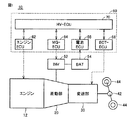
図1は、この発明の実施の形態に従うハイブリッド車10の全体構成図である。図1を参照して、ハイブリッド車10は、エンジン12と、差動部20と、変速部30と、差動歯車装置42と、駆動輪44とを備える。また、ハイブリッド車10は、インバータ52と、蓄電装置54と、制御装置60とをさらに備える。
(Overall configuration of hybrid vehicle)
FIG. 1 is an overall configuration diagram of a
エンジン12は、内燃機関であり、たとえばガソリンエンジンやディーゼルエンジン等によって構成される。エンジン12は、燃料の燃焼による熱エネルギーをピストンやロータなどの運動子の運動エネルギーに変換し、その変換された運動エネルギーを差動部20へ出力する。たとえば、エンジン12の回転軸の運動エネルギーが、差動部20に伝達される。
The
差動部20は、エンジン12に連結される。差動部20は、後述のように、インバータ52によって駆動されるモータジェネレータと、エンジン12の出力を変速部30への伝達部材とモータジェネレータとに分割する動力分割装置とを含む。差動部20の構成については、後ほど説明する。
The
変速部30は、差動部20に連結され、差動部20に接続される上記伝達部材(変速部30の入力軸)の回転速度と差動歯車装置42に接続される駆動軸(変速部30の出力軸)の回転速度との比(変速比)を変更可能に構成される。なお、この実施の形態では、変速部30は、変速比を段階的に変更可能な有段式の変速機によって構成されるものとするが、無段式の変速機によって構成してもよい。差動歯車装置42は、変速部30の出力軸に連結され、変速部30から出力される動力を駆動輪44へ伝達する。変速部30の構成についても、差動部20とともに後ほど説明する。
The
インバータ52は、蓄電装置54に電気的に接続され、制御装置60からの制御信号に基づいて、差動部20に含まれるモータジェネレータを駆動する。インバータ52は、たとえば、三相分の電力用半導体スイッチング素子を含むブリッジ回路によって構成される。なお、特に図示しないが、インバータ52と蓄電装置54との間に電圧コンバータを設けてもよい。
蓄電装置54は、再充電可能な直流電源であり、代表的には、リチウムイオン電池やニッケル水素電池などのバッテリによって構成される。蓄電装置54は、走行用を含む電力を蓄え、その蓄積電力をインバータ52へ供給する。また、蓄電装置54は、差動部20のモータジェネレータによって発電される電力をインバータ52から受けることによっても充電される。なお、電気二重層キャパシタなどの、バッテリ以外の蓄電要素によって蓄電装置54を構成してもよい。
The
制御装置60は、エンジンECU(Electronic Control Unit)62と、MG−EC
U64と、電池ECU66と、ECT−ECU68と、HV−ECU70とを含む。これらの各ECUは、CPU(Central Processing Unit)、記憶装置、入出力バッファ等
を含み(いずれも図示せず)、後述の各種制御を実行する。なお、各ECUにより実行される制御については、ソフトウェアによる処理に限られず、専用のハードウェア(電子回路)で処理することも可能である。なお、本実施の形態では、制御装置60は、上記の各ECUによって構成されるものとするが、制御装置60を単一のECUによって構成してもよい。
The control device 60 includes an engine ECU (Electronic Control Unit) 62 and an MG-EC.
U64,
エンジンECU62は、HV−ECU70から受けるエンジントルク指令等に基づいて、エンジン12を駆動するためのスロットル信号や点火信号、燃料噴射信号等を生成し、その生成した各信号をエンジン12へ出力する。MG−ECU64は、HV−ECU70からの指令に基づいて、インバータ52を制御するための制御信号を生成し、その生成した制御信号をインバータ52へ出力する。
The
電池ECU66は、図示されない電圧センサおよび電流センサによって検出される蓄電装置54の電圧および電流に基づいて、蓄電装置54の充電状態(「SOC(State Of Charge)」とも称され、たとえば満充電状態を100%として0〜100%で表わされる。)を推定し、その推定結果をHV−ECU70へ出力する。ECT−ECU68は、HV−ECU70から受けるトルク容量指令等に基づいて、変速部30を制御するための油圧指令を生成し、その生成した油圧指令を変速部30へ出力する。
HV−ECU70は、各種センサの検出信号を受け、ハイブリッド車10の各機器を制御するための各種指令を生成する。HV−ECU70により実行される主要な制御の一つとして、HV−ECU70は、車両の走行状態(たとえば、アクセルペダルの操作量や車両速度等)に応じて、エンジン12を停止させた状態でモータジェネレータのみを動力源として走行する「EV走行」と、エンジン12を動作させた状態で走行する「HV走行」とを組み合わせるように、ハイブリッド車10の走行を制御する。
The HV-
たとえば、HV−ECU70は、走行状態に応じて変化する車両走行パワーが小さい領域(低速、軽負荷走行)では、エンジン12を停止したEV走行を選択する一方で、車両走行パワーが大きい領域(加速、高速走行)では、エンジン12を作動したHV走行を選択する。すなわち、ハイブリッド車10では、車両運転中に、作動状態のエンジン12が停止されたり、反対に停止状態のエンジン12が始動されることを自動的に繰り返す。すなわち、エンジン12は、走行状態に応じて間欠運転される。
For example, the HV-
さらに、走行制御において、HV−ECU70は、走行状態に基づいて、エンジン12、差動部20および変速部30を所望の状態に制御する。また、HV−ECU70は、変速部30の変速中、エンジン12および差動部20の挙動を所望の目標に制御する変速制御を実行する。
Further, in the traveling control, the HV-
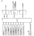
図2は、図1に示した制御装置60に対して入出力される主な信号及び指令を示した図である。図2を参照して、HV−ECU70は、ハイブリッド車10の速度を検出する車速センサからの信号、アクセルペダルの操作量を検出するアクセル開度センサからの信号、エンジン12の回転数を検出するエンジン回転数センサからの信号を受ける。また、HV−ECU70は、差動部20に含まれるモータジェネレータMG1(後述)の回転速度を検出するためのMG1回転数センサからの信号、差動部20に含まれるモータジェネレータMG2(後述)の回転速度を検出するためのMG2回転数センサからの信号、変速部30の出力軸の回転速度を検出するための出力軸回転数センサからの信号をさらに受ける。
FIG. 2 is a diagram showing main signals and commands input / output to / from control device 60 shown in FIG. Referring to FIG. 2, HV-
さらに、HV−ECU70は、差動部20及び変速部30の潤滑油の温度を検出する潤滑油温度センサからの信号、シフトレバーによって指示されるシフトポジションを検出するシフトポジションセンサからの信号、エンジン冷却水の温度を検出する水温センサからの信号をさらに受ける。さらに、HV−ECU70は、蓄電装置54のSOCを示す信号、蓄電装置54の充電電力の上限を示す充電可能電力Winを示す信号、蓄電装置54の放電電力の上限を示す放電可能電力Woutを示す信号等を電池ECU66から受ける。電池ECU66は、蓄電装置54の低SOC時または低温時ないし高温時には、放電電力を制限するために放電可能電力Woutを抑制する。同様に、高SOC時または低温時ないし高温時には、充電電力を制限するために充電可能電力Winが抑えられる。
Further, the HV-
HV−ECU70は、車両の走行状態(たとえば、アクセルペダルの操作量や車両速度等)に応じた走行制御により、車両のエネルギー効率を考慮して、エンジン12およびモータジェネレータMG1,MG2間の出力配分を制御する。上述したエンジン12の間欠運転は、この出力配分制御に従って実行される。
The HV-
HV−ECU70は、上記走行制御(出力配分制御)に従って、エンジン12の出力トルクの目標を示すエンジントルク指令Ter、差動部20のモータジェネレータMG1,MG2を駆動するためのトルク指令Tgr,Tmr、および、変速部30を制御するためのトルク容量指令Tcrを生成する。たとえば、HV−ECU70は、所定の変速マップに従って変速部30の変速段を決定し、その変速段を実現するためのトルク容量指令Tcrを生成する。
The HV-
エンジントルク指令Terを受けたエンジンECU62は、エンジン12を駆動するためのスロットル信号や点火信号、燃料噴射信号等を生成してエンジン12へ出力する。エンジン12の停止時には、Ter=0に設定されることにより、エンジン12での燃料噴射および点火を停止して、燃料燃焼を停止することができる。あるいは、エンジントルク指令Terとは独立に、エンジン12での燃料燃焼の停止/実行を指令する信号が設けられてもよい。
Upon receiving the engine torque command Ter, the
トルク指令Tgr,Tmrを受けたMG−ECU64は、トルク指令Tgr,Tmrに相当するトルクをモータジェネレータMG1,MG2が発生するようにインバータ52を制御するための信号PWIを生成し、その生成された信号PWIをインバータ52へ出力する。なお、トルク指令Tgr,Tmrは、モータジェネレータMG1,MG2での入出力電力(回転数×トルク)の和が、上記Win〜Woutの範囲内となるように制限される。したがって、蓄電装置54のSOCや温度に依存して、トルク指令Tgr,Tmrが制限され得る。
The MG-
トルク容量指令Tcrを受けたECT−ECU68は、トルク容量指令Tcrに相当するトルク容量を変速部30が有するように油圧指令を生成し、その生成された油圧指令を変速部30へ出力する。
The ECT-
(差動部および変速部の構成)
図3は、図1に示した差動部20および変速部30の構成を示した図である。なお、この実施の形態では、差動部20および変速部30は、その軸心に対して対称的に構成されているので、図3では、差動部20および変速部30の下側を省略して図示されている。
(Configuration of differential unit and transmission unit)
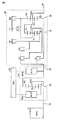
FIG. 3 is a diagram illustrating the configuration of the
図3を参照して、差動部20は、モータジェネレータMG1,MG2と、動力分割装置24とを含む。モータジェネレータMG1,MG2の各々は、交流電動機であり、たとえば、永久磁石が埋設されたロータを備える永久磁石型同期電動機によって構成される。モータジェネレータMG1,MG2は、インバータ52によって駆動される。
Referring to FIG. 3,
動力分割装置24は、シングルピニオン型のプラネタリギヤによって構成され、サンギヤS0と、ピニオンギヤP0と、キャリアCA0と、リングギヤR0とを含む。キャリアCA0は、入力軸22すなわちエンジン12の出力軸に連結され、ピニオンギヤP0を自転および公転可能に支持する。サンギヤS0は、モータジェネレータMG1の回転軸に連結される。リングギヤR0は、伝達部材26に連結され、ピニオンギヤP0を介してサンギヤS0と噛み合うように構成される。伝達部材26には、モータジェネレータMG2の回転軸が連結される。すなわち、リングギヤR0は、モータジェネレータMG2の回転軸とも連結される。
Power split
動力分割装置24は、サンギヤS0、キャリアCA0およびリングギヤR0が相対的に回転することによって差動装置として機能する。サンギヤS0、キャリアCA0およびリングギヤR0の各回転数は、後述(図5)するように共線図において直線で結ばれる関係になる。動力分割装置24の差動機能により、エンジン12から出力される動力がサンギヤS0とリングギヤR0とに分配される。そして、サンギヤS0に分配された動力によってモータジェネレータMG1が発電機として作動し、モータジェネレータMG1により発電された電力は、モータジェネレータMG2に供給されたり、蓄電装置54(図1)に蓄えられたりする。
Power split
また、モータジェネレータMG1の出力トルクによって、エンジン12の出力軸に対して加減速のための回転力を付与することができる。したがって、停止状態のエンジン12を始動する際には、モータジェネレータMG1によってエンジン12にクランキングトルクを付与して、エンジン回転数が上昇した後に、エンジン12での燃料噴射および点火(すなわち、燃料燃焼)を開始するように、エンジン始動制御が実行される。すなわち、HV−ECU70は、エンジン始動の際には、モータジェネレータMG1のトルク指令Tgrを、エンジン始動制御に従って設定する。
Further, the torque for acceleration / deceleration can be applied to the output shaft of
変速部30は、シングルピニオン型のプラネタリギヤ32,34と、クラッチC1〜C3と、ブレーキB1,B2と、ワンウェイクラッチF1とを含む。プラネタリギヤ32は、サンギヤS1と、ピニオンギヤP1と、キャリアCA1と、リングギヤR1とを含む。プラネタリギヤ34は、サンギヤS2と、ピニオンギヤP2と、キャリアCA2と、リングギヤR2とを含む。
The
クラッチC1〜C3およびブレーキB1,B2の各々は、油圧により作動する摩擦係合装置であり、重ねられた複数枚の摩擦板が油圧により押圧される湿式多板型や、回転するドラムの外周面に巻付けられたバンドの一端が油圧によって引き締められるバンドブレーキ等によって構成される。ワンウェイクラッチF1は、互いに連結されるキャリアCA1およびリングギヤR2を一方向に回転可能とし、かつ、他方向に回転不能に支持する。 Each of the clutches C1 to C3 and the brakes B1 and B2 is a friction engagement device that operates by hydraulic pressure, and a wet multi-plate type in which a plurality of stacked friction plates are pressed by hydraulic pressure, or an outer peripheral surface of a rotating drum One end of a band wound around the belt is constituted by a band brake or the like that is tightened by hydraulic pressure. The one-way clutch F1 supports the carrier CA1 and the ring gear R2 connected to each other so as to be rotatable in one direction and not rotatable in the other direction.
この変速部30においては、クラッチC1〜C3およびブレーキB1,B2、ならびにワンウェイクラッチF1の各係合装置が、図4に示される係合作動表に従って係合されることにより、1速ギヤ段〜4速ギヤ段および後進ギヤ段が択一的に形成される。なお、図4において、「○」は係合状態であることを示し、「(○)」はエンジンブレーキ時に係合されることを示し、「△」は駆動時にのみ係合されることを示し、空欄は解放状態であることを示す。また、クラッチC1〜C3およびブレーキB1,B2の各係合装置をすべて解放状態にすることにより、ニュートラル状態(動力伝達が遮断された状態)を形成することができる。
In the
再び図3を参照して、差動部20と変速部30とは、伝達部材26によって連結される。そして、プラネタリギヤ34のキャリアCA2に連結される出力軸36が差動歯車装置42(図1)に連結される。
Referring to FIG. 3 again, the
図5は、差動部20および変速部30によって構成される変速機構の共線図である。図5とともに図3を参照して、差動部20に対応する共線図の縦線Y1は、動力分割装置24のサンギヤS0の回転数を示し、すなわちモータジェネレータMG1の回転数を示す。縦線Y2は、動力分割装置24のキャリアCA0の回転数を示し、すなわちエンジン12の回転数を示す。縦線Y3は、動力分割装置24のリングギヤR0の回転数を示し、すなわちモータジェネレータMG2の回転数を示す。なお、縦線Y1〜Y3の間隔は、動力分割装置24のギヤ比に応じて定められている。
FIG. 5 is a collinear diagram of the speed change mechanism constituted by the
また、変速部30に対応する共線図の縦線Y4は、プラネタリギヤ34のサンギヤS2の回転数を示し、縦線Y5は、互いに連結されたプラネタリギヤ34のキャリアCA2およびプラネタリギヤ32のリングギヤR1の回転数を示す。また、縦線Y6は、互いに連結されたプラネタリギヤ34のリングギヤR2およびプラネタリギヤ32のキャリアCA1の回転数を示し、縦線Y7は、プラネタリギヤ32のサンギヤS1の回転数を示す。そして、縦線Y4〜Y7の間隔は、プラネタリギヤ32,34のギヤ比に応じて定められている。
The vertical line Y4 in the collinear diagram corresponding to the
クラッチC1が係合すると、差動部20のリングギヤR0にプラネタリギヤ34のサンギヤS2が連結され、サンギヤS2がリングギヤR0と同じ速度で回転する。クラッチC2が係合すると、リングギヤR0にプラネタリギヤ32のキャリアCA1およびプラネタリギヤ34のリングギヤR2が連結され、キャリアCA1およびリングギヤR2がリングギヤR0と同じ速度で回転する。クラッチC3が係合すると、リングギヤR0にプラネタリギヤ32のサンギヤS1が連結され、サンギヤS1がリングギヤR0と同じ速度で回転する。ブレーキB1が係合するとサンギヤS1の回転が停止し、ブレーキB2が係合するとキャリアCA1およびリングギヤR2の回転が停止する。
When the clutch C1 is engaged, the sun gear S2 of the
たとえば、図4の係合作動表に示したように、クラッチC1およびブレーキB1を係合し、その他のクラッチおよびブレーキを解放すると、変速部30の共線図は「2nd」で
示される直線のようになる。プラネタリギヤ34のキャリアCA2の回転数を示す縦線Y5が、変速部30の出力回転数(出力軸36の回転数)を示す。このように、変速部30において、クラッチC1〜C3およびブレーキB1,B2を図4の係合作動表に従って係合または解放させることにより、1速ギヤ段〜4速ギヤ段、後進ギヤ段、およびニュートラル状態を形成することができる。
For example, as shown in the engagement operation table of FIG. 4, when the clutch C1 and the brake B1 are engaged and the other clutches and brakes are released, the alignment chart of the
このように、本実施の形態に従うハイブリッド車10では、図1および図3に示されるように、エンジン12の回転軸から駆動輪44までの動力伝達経路に変速部30が含まれている。
As described above, in
一般的に、車両の駆動系では、動力伝達機構によって機械振動系が構成される。機械振動系では、固有周波数(共振周波数)の振動に対して共振現象が励起されることが知られている。共振周波数に対応する特定回転数(以下、共振回転数とも称する)と一致するエンジン回転数において、共振現象によって車両振動が生じることが懸念される。 Generally, in a vehicle drive system, a mechanical vibration system is configured by a power transmission mechanism. In a mechanical vibration system, it is known that a resonance phenomenon is excited by vibration of a natural frequency (resonance frequency). There is a concern that vehicle vibration may occur due to a resonance phenomenon at an engine speed that matches a specific speed corresponding to the resonance frequency (hereinafter also referred to as the resonance speed).
機械振動系における共振周波数は、ハードウェアの形状および質量(モーメント)によって決まる固有値である。したがって、特許文献1にも記載されるように、動力伝達経路に変速機が含まれる構成では、変速機で形成されるギヤ段(変速比)が変わると、クラッチおよびブレーキの状態(係合/解放)が変化することにより、回転軸に対する慣性モーメントが変化することにより、共振周波数も変わる傾向にある。
The resonance frequency in the mechanical vibration system is an eigenvalue determined by the shape and mass (moment) of hardware. Therefore, as described in
図6は、変速部30の変速比(ギヤ段)に対する共振周波数の変化の例を説明するための概念図である。図6の横軸には、機械振動系に入力される振動の周波数が示され、縦軸には当該振動の増幅度合(dB)が示されている。
FIG. 6 is a conceptual diagram for explaining an example of a change in the resonance frequency with respect to the gear ratio (gear stage) of the
図6を参照して、特性線201〜204は、図4に示された1速ギヤ段(1st)〜4速ギヤ段(4th)のそれぞれにおける周波数特性を模式的に示している。動力伝達機構(駆動系)の共振周波数は、1速ギヤ段の形成時にはfr1であり、2速ギヤ段の形成時にはfr2であり、3速ギヤ段の形成時にはfr3であり、4速ギヤ段の形成時にはfr4である。以下では、共振周波数fr1〜fr4にそれぞれ対応するエンジン回転数(共振回転数)をNr1〜Nr4で示すこととする。なお、ハイブリッド車10の駆動系の周波数特性は、その構造によって種々の態様を取り得るが、以下では、ハイブリッド車10の駆動系が図6に示すような周波数特性を有するものとして説明を進める。
Referring to FIG. 6,
図6から理解されるように、変速部30によって形成されるギヤ段(変速比)が変化すると、エンジン12の共振回転数も変化する。エンジン12が自動的に間欠運転されるハイブリッド車10では、エンジン始動の頻度が高くなり、かつ、エンジン始動時における変速部30の変速比(ギヤ段)が固定されないため、変速比(ギヤ段)に対応させてエンジン12の始動時の振動を抑制するためのエンジン始動制御が重要となる。
As understood from FIG. 6, when the gear stage (gear ratio) formed by the
特許文献1に記載されたエンジン始動制御では、共振回転数が高くなるギヤ段の形成時には、クランキングトルクを増大させることによって振動を抑制する制御が記載されている。しかしながら、このようなエンジン始動制御では、バッテリの出力低下時(たとえば、低温時または低SOC時等)に、クランキングトルクが制限されることにより、振動の抑制が不十分となることが懸念される。
The engine start control described in
したがって、本実施の形態に従うハイブリッド車では、ギヤ段(変速比)の変化に対応させてクランキングトルクを変化することによって、エンジン12の共振回転数帯を迅速に超えるための、エンジン始動時におけるエンジン回転数の制御パターン(以下、「エンジン始動パターン」とも称する)を切換えるエンジン始動制御を適用する。
Therefore, in the hybrid vehicle according to the present embodiment, the cranking torque is changed in response to the change of the gear stage (speed ratio), so that the resonance speed range of
図7は、共振回転数が低いギヤ段(変速比)の形成時におけるエンジン始動パターンを説明するための概念的な波形図である。たとえば、図7のエンジン始動パターンは、変速部30が1速ギヤ段または2速ギヤ段(以下、包括的に「Loギヤ」とも称する)を形成している場合に適用される。Loギヤは、低速用の変速比(減速比)が大きいギヤ段である。
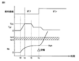
FIG. 7 is a conceptual waveform diagram for explaining an engine start pattern when a gear stage (gear ratio) having a low resonance speed is formed. For example, the engine start pattern of FIG. 7 is applied when the
図7を参照して、時刻t0以前では、エンジン12は停止状態である。すなわち、エンジン回転数Ne=0であるとともに、エンジン12での燃料噴射および点火が停止されて、燃料燃焼がオフされた状態である。
Referring to FIG. 7,
時刻t0において、停止状態のエンジン12に対して始動指令が発せられると、モータジェネレータMG1によってエンジン12をクランキングするために、所定のトルクパターンに従って、モータジェネレータMG1のトルク指令Tgrが設定される。たとえば、トルク指令Tgrは、クランキングトルクの指令値Tslまで一定レートで上昇され(時刻t1〜t2)、一定期間Tslに維持される(時刻t1〜t2)。
When a start command is issued to
クランキングトルクの付与に応じて、エンジン回転数Neが上昇する。図7のエンジン始動パターンでは、エンジン回転数Neは、燃料燃焼がオフされた状態下で、共振回転数Nr1,Nr2を含む周波数帯を通過する。 The engine speed Ne increases in accordance with the application of the cranking torque. In the engine start pattern of FIG. 7, the engine speed Ne passes through a frequency band including the resonance speeds Nr1 and Nr2 in a state where the fuel combustion is turned off.
時刻t2から、クランキングトルクが低減されることにより、エンジン回転数Neは維持される(Ne=Nsl)。この状態で、エンジン12での燃料噴射が開始され、時刻t3において初回の点火(いわゆる、初爆)が実行される。これにより、エンジン12での燃料燃焼が開始される。燃料燃焼によるエンジントルクによって、エンジン回転数Neは、初爆回転数よりも上昇する。これにより、エンジン始動制御が終了される。
Since the cranking torque is reduced from time t2, the engine speed Ne is maintained (Ne = Nsl). In this state, fuel injection in the
図7の始動パターンでは、エンジン12が初爆されるときのエンジン回転数(初爆回転数)は、Ne=Nslであり、共振回転数Nr1,Nr2よりも高い。したがって、エンジン回転数Neは、クランキングトルクによる加速力によって、共振回転数Nr1,Nr2を含む周波数帯を通過する。したがって、クランキングトルクの指令値Tslは、エンジン回転数Neが、共振回転数Ns1,Ns2を迅速に通過できるように、設定される必要がある。ただし、図7の始動パターンは、共振回転数が低いギヤ段(変速比)の形成時に適用されるため、クランキングトルクをそれ程高くしなくても、共振回転数領域を迅速に通過することができる。
In the starting pattern of FIG. 7, the engine speed (initial explosion speed) when the
図8は、共振回転数が高いギヤ段(変速比)の形成時におけるエンジン始動パターンを説明するための概念的な波形図である。たとえば、図8のエンジン始動パターンは、変速部30が3速ギヤ段または4速ギヤ段(以下、包括的に「Hiギヤ」とも称する)を形成している場合に適用される。Hiギヤは、高速用の変速比(減速比)が小さいギヤ段である。
FIG. 8 is a conceptual waveform diagram for explaining an engine start pattern when a gear stage (gear ratio) having a high resonance speed is formed. For example, the engine start pattern of FIG. 8 is applied when the
図8においても、時刻t0において、停止状態のエンジン12に対して始動指令が発せられる。Hiギヤの形成時における共振回転数Nr3,Nr4は、Loギヤ形成時の共振回転数Nr1,Nr2(図7)よりも高い。
Also in FIG. 8, a start command is issued to the stopped
始動指令が発せられると(時刻t0)、所定のトルクパターンに従って、モータジェネレータMG1がクランキングトルクを出力するためのトルク指令Tgrが設定される。トルク指令Tgrは、クランキングトルクの指令値Tshまで一定レートで上昇され(時刻t1〜ta)、一定期間Tshに維持される(時刻ta〜tb)。 When a start command is issued (time t0), torque command Tgr for motor generator MG1 to output cranking torque is set according to a predetermined torque pattern. The torque command Tgr is increased at a constant rate up to the cranking torque command value Tsh (time t1 to ta) and is maintained for a certain period Tsh (time ta to tb).
クランキングトルクの付与に応じて、エンジン回転数Neが上昇される。さらに、時刻tbから、クランキングトルクが低減されることにより、エンジン回転数Neは維持される(Ne=Nsh)。この際に、クランキングトルクを低く設定している(Tsh<Tsl)ので、初爆回転数Nshが、Hiギヤ形成時の共振回転数Nr3,Nr4よりも低い。 The engine speed Ne is increased according to the application of the cranking torque. Further, the engine speed Ne is maintained (Ne = Nsh) by reducing the cranking torque from time tb. At this time, since the cranking torque is set low (Tsh <Tsl), the initial explosion speed Nsh is lower than the resonance speeds Nr3 and Nr4 when the Hi gear is formed.
そして、時刻tcにおいて、エンジン12は初爆されて、燃料燃焼を開始する。Hiギヤ形成時の共振回転数Nr3,Nr4よりも低い。したがって、図8の始動パターンでは、エンジン回転数Neは、エンジン12の燃料燃焼によるトルクによって、共振回転数Nr3,Nr4を含む周波数帯を迅速に通過することができる。燃料燃焼の継続によってエンジン回転数Neがさらに上昇すると、エンジン始動制御が終了される。
At time tc, the
図8の始動パターンでは、クランキングトルクを低く設定することにより(Tsh<Tsl)ため、共振回転数が高いギヤ段(変速比)が形成されている場合でも、モータジェネレータMG1によるクランキングトルクを増大させることなく、エンジン始動時の振動を抑制することができる。 In the starting pattern of FIG. 8, since the cranking torque is set low (Tsh <Tsl), the cranking torque generated by the motor generator MG1 is reduced even when a gear stage (speed ratio) having a high resonance speed is formed. Without increasing, it is possible to suppress vibration at the time of engine start.
なお、それぞれの始動パターンにおける初爆回転数NslおよびNshは、クランキングトルクの高低関係に従って、一般的には、Nsl>Nshとなる。 It should be noted that the initial explosion speeds Nsl and Nsh in each start pattern generally satisfy Nsl> Nsh in accordance with the cranking torque level.
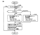
図9は、本発明の実施の形態に従うハイブリッド車におけるエンジン始動制御を説明するためのフローチャートである。図9に示されたフローチャートは、エンジン12の停止状態時に繰返し実行される。図9に示したフローチャートに従う制御処理を実行することによって、図7および図8に示したエンジン始動パターンが選択的に実行される。
FIG. 9 is a flowchart for illustrating engine start control in the hybrid vehicle according to the embodiment of the present invention. The flowchart shown in FIG. 9 is repeatedly executed when the
図9を参照して、制御装置60(HV−ECU70)は、ステップS100により、エンジン始動指令が発せられる条件が成立しているかどうかを判定する。たとえば、エンジン12の停止状態において、アクセルペダルの踏込み等によって車両走行パワーが高まったときなどに、ステップS100のYES判定とされる。
Referring to FIG. 9, control device 60 (HV-ECU 70) determines in step S100 whether a condition for issuing an engine start command is satisfied. For example, when the vehicle running power is increased due to depression of the accelerator pedal or the like while the
エンジン始動指令が発せられると(S100のYES判定時)、制御装置60(HV−ECU70)は、変速部30において形成されている変速比を判別する。たとえばステップS110では、低速用のLoギヤ(1速ギヤまたは2速ギヤ)が選択されているかどうかが判定される。Loギヤの形成時(S110のYES判定時)には、制御装置60(HV−ECU70)は、ステップS120に処理を進めて、図7に示された第1の始動パターンに従ってエンジン12を始動するように、クランキングトルク(Tsl)を設定する。これにより、初爆回転数Nslは、Loギヤ形成時の共振回転数Nr1,Nr2よりも高くなる。
When an engine start command is issued (YES in S100), control device 60 (HV-ECU 70) determines the gear ratio formed in
一方で、制御装置60(HV−ECU70)は、Hiギヤ(3速ギヤまたは4速ギヤ)の形成時(S110のNO判定時)には、ステップS130に処理を進めて、図8に示した第2の始動パターンに従ってエンジン始動制御を実行するようにクランキングトルク(Tsh)を設定する。第2の始動パターンにおけるクランキングトルクTshは、第1の始動パターンにおけるクランキングトルクTslよりも低い。初爆回転数Nshは、Hiギヤ形成時の共振回転数Nr3,Nr4よりも低くなる。 On the other hand, control device 60 (HV-ECU 70) proceeds to step S130 when the Hi gear (third gear or fourth gear) is formed (NO in S110), as shown in FIG. Cranking torque (Tsh) is set so as to execute engine start control according to the second start pattern. The cranking torque Tsh in the second start pattern is lower than the cranking torque Tsl in the first start pattern. The initial explosion speed Nsh is lower than the resonance speeds Nr3 and Nr4 when the Hi gear is formed.
さらに、制御装置60(HV−ECU70)は、ステップS200において、ステップS120またはS130によって選択された始動パターンに従って、エンジン12が始動されるように、エンジン12の動作指令(たとえば、エンジントルク指令Ter)および、モータジェネレータMG1,MG2の動作指令(たとえば、トルク指令Tgr,Tmr)を生成する。
Further, in step S200, control device 60 (HV-ECU 70) operates
HV−ECU70からの動作指令に従って、エンジンECU62およびMG−ECU64が、エンジン12およびモータジェネレータMG1,MG2を制御することにより、エンジン12の始動時には、クランキングトルクによってエンジン回転数を初爆回転数まで上昇させた後に、エンジン12における燃料燃焼を開始するエンジン始動制御を、形成されているギヤ段(変速比)に応じて選択された始動パターン(図7、図8)に従って実行することができる。
The
なお、エンジン始動制御において、初爆回転数は、直接制御されなくてもよい。すなわち、実機実験やシミュレーション結果に従って、所望の初爆回転数となるように、クランキングトルクの値(Tsl,Tsh)およびパターンを予め調整することができる。あるいは、本実施の形態では、初爆回転数と共振回転数との高低が重要となることに鑑み、クランキング時におけるエンジン回転数をフィードバック制御することによって、初爆回転数を精密に制御することも可能である。たとえば、図7の時刻t1〜t3または図8のta〜tc間におけるモータジェネレータMG1のトルク指令Tgrは、エンジン回転数を所望の初爆回転数に一致させるためのフィードバック制御によって設定することも可能である。 In the engine start control, the initial explosion speed may not be directly controlled. That is, according to actual machine experiments and simulation results, the cranking torque values (Tsl, Tsh) and the pattern can be adjusted in advance so as to obtain a desired initial explosion speed. Alternatively, in the present embodiment, in consideration of the importance of the initial explosion speed and the resonance rotational speed, the initial explosion speed is precisely controlled by feedback control of the engine speed at the time of cranking. It is also possible. For example, torque command Tgr of motor generator MG1 between times t1 to t3 in FIG. 7 or ta to tc in FIG. 8 can be set by feedback control for making the engine speed coincide with a desired initial explosion speed. It is.
このように、本実施の形態に従うハイブリッド車においては、変速部30のギヤ段(変速比)に応じて駆動系(動力伝達機構)の共振周波数が変化する構成において、ギヤ段(変速比)の変化に対応させて、クランキングトルクを変化させる。具体的には、共振周波数が高いギヤ段(変速比)の形成時にクランキングトルクを低下させることにより、燃料燃焼によるエンジントルクによって共振回転数を通過する始動パターンを適用できるので、モータジェネレータMG1の電源となるバッテリの出力低下時(低SOCまたは低温時)においても、エンジン始動時の振動を抑制することが可能となる。
Thus, in the hybrid vehicle according to the present embodiment, in the configuration in which the resonance frequency of the drive system (power transmission mechanism) changes according to the gear stage (transmission ratio) of
より詳細には、ギヤ段(変速比)に応じてクランキングトルクを変化させることで、クランキングトルクによって共振回転数を通過する始動パターンと、燃料燃焼によるエンジントルクによって共振回転数を通過する始動パターンとを使い分けることによって、エンジン始動時の振動を適切に抑制することができる。 More specifically, by changing the cranking torque according to the gear stage (speed ratio), a start pattern that passes the resonance speed by the cranking torque, and a start that passes the resonance speed by the engine torque by fuel combustion By properly using the pattern, vibration at the time of engine start can be appropriately suppressed.
また、図7〜9では、Hiギヤ(3速ギヤおよび4速ギヤ)またはLoギヤ(1速ギヤまたは2速ギヤ)に分類して、クランキングトルク(および初爆回転数)を二種類に設定したが、ギヤ段毎に異なるクランキングトルク(および初爆回転数)を設定してもよい。 Also, in FIGS. 7 to 9, the cranking torque (and the initial explosion speed) is classified into two types, classified into Hi gear (3rd gear and 4th gear) or Lo gear (1st gear or 2nd gear). Although set, different cranking torque (and initial explosion speed) may be set for each gear stage.
たとえば、図10に示すように、1速ギヤ段(1st)〜4速ギヤ段(4th)のそれぞれに対してクランキングトルクTs1〜Ts4(および初爆回転数Nsl〜Ns4)をそれぞれ設定するように、エンジン始動制御を実行してもよい。 For example, as shown in FIG. 10, cranking torques Ts1 to Ts4 (and initial explosion speed Nsl to Ns4) are set for each of the first gear (1st) to the fourth gear (4th). In addition, the engine start control may be executed.
この場合にも、各ギヤ段に対して設定されたクランキングトルクによって、一部のギヤ段に対しては、図7に示した第1の始動パターンが適用されて、初爆回転数は、当該ギヤ段の形成時における共振回転数よりも高くなる。また、その他のギヤ段に対しては、図8に示したクランキングトルクを低下させた第2の始動パターンが適用される。第2の始動パターンでは、初爆回転数は当該ギヤ段の形成時における共振回転数よりも低くなる。 In this case as well, the first start pattern shown in FIG. 7 is applied to some gears by the cranking torque set for each gear, and the initial explosion speed is It becomes higher than the resonance rotational speed when the gear stage is formed. Further, the second start pattern in which the cranking torque shown in FIG. 8 is reduced is applied to other gear stages. In the second start pattern, the initial explosion speed is lower than the resonance speed when the gear stage is formed.
なお、本実施の形態では、変速部が有段変速機によって構成される例を説明したが、変速比に応じて変速機を含む動力伝達機構の共振周波数が変化する構造である限り、変速部が無段変速機によって構成される場合にも本発明は適用可能である。たとえば、無段変速機による変速比に応じたエンジンの共振回転数の変化に対応させて、エンジン始動時の変速比に応じて、クランキングトルクが異なる第1および第2の始動パターンを選択するエンジン始動制御を、同様に適用することができる。 In the present embodiment, the example in which the transmission unit is configured by a stepped transmission has been described. However, as long as the resonance frequency of the power transmission mechanism including the transmission changes according to the transmission ratio, the transmission unit The present invention can also be applied to a case where is configured by a continuously variable transmission. For example, the first and second start patterns having different cranking torques are selected according to the speed ratio at the start of the engine in response to a change in the engine's resonant rotational speed according to the speed ratio of the continuously variable transmission. Engine start control can be applied as well.
また、ハイブリッド車の駆動系の構成についても、図1の例示に限定されるものではなく、変速機の変速比(ギヤ段)の変化に応じて駆動系(動力伝達機構)の共振周波数が変化するような構造であれば、本実施の形態に従うエンジン始動制御を共通に適用することができる。 Further, the configuration of the drive system of the hybrid vehicle is not limited to the example shown in FIG. 1, and the resonance frequency of the drive system (power transmission mechanism) changes according to the change in the transmission gear ratio (gear stage). With such a structure, the engine start control according to the present embodiment can be commonly applied.
なお、本実施の形態では、変速比が大きい低速用のギヤ段(Loギヤ段)となるほど共振周波数(共振回転数)が低くなり、変速比が小さい高速用のギヤ段(Hiギヤ)となるほど共振周波数(共振回転数)が高くなる周波数特性を示したが、本実施の形態に従うエンジン始動制御の適用はこのような例に限定されるものではない。すなわち、変速比に応じて共振周波数(すなわち、エンジンの共振回転数)が変化する周波数特性が把握されている限り、エンジンの共振回転数の高低に対応させて、第1および第2の始動パターンを選択的に適用することにより、同様の効果を享受することができる。 In this embodiment, the lower the gear ratio for low speed (Lo gear stage) with a larger gear ratio, the lower the resonance frequency (resonance rotation speed), and the higher the gear stage for high speed (Hi gear) with a smaller gear ratio. Although the frequency characteristic in which the resonance frequency (resonance rotation speed) increases is shown, the application of the engine start control according to the present embodiment is not limited to such an example. That is, as long as a frequency characteristic in which the resonance frequency (that is, the engine resonance speed) changes according to the gear ratio is known, the first and second start patterns corresponding to the resonance speed of the engine. The same effect can be enjoyed by selectively applying.
今回開示された実施の形態はすべての点で例示であって制限的なものではないと考えられるべきである。本発明の範囲は上記した説明ではなくて特許請求の範囲によって示され、特許請求の範囲と均等の意味および範囲内でのすべての変更が含まれることが意図される。 The embodiment disclosed this time should be considered as illustrative in all points and not restrictive. The scope of the present invention is defined by the terms of the claims, rather than the description above, and is intended to include any modifications within the scope and meaning equivalent to the terms of the claims.
10 ハイブリッド車、12 エンジン、20 差動部、22 入力軸、24 動力分割装置、26 伝達部材、30 変速部、32,34 プラネタリギヤ、36 出力軸、42 差動歯車装置、44 駆動輪、52 インバータ、54 蓄電装置、60 制御装置、62 エンジンECU、64 MG−ECU、66 電池ECU、68 ECT−ECU、201〜204 特性線(周波数特性)、B1,B2 ブレーキ、C1,C2,C3 クラッチ、CA0,CA1,CA2 キャリア、F1 ワンウェイクラッチ、MG1,MG2 モータジェネレータ、Ne エンジン回転数、Nr1〜Nr4 共振回転数、Ns1〜Ns4,Nsh,Nsl 初爆回転数、P0,P1,P2 ピニオンギヤ、R0,R1,R2 リングギヤ、S0,S1,S2 サンギヤ、Tcr トルク容量指令、Ter エンジントルク指令、Tgr,Tmr トルク指令(MG1,MG2)、Ts1〜Ts4,Tsh,Tsl クランキングトルク、Wout 放電可能電力、fr1〜fr4 共振周波数。
DESCRIPTION OF
Claims (3)
前記エンジンの始動時にクランキングトルクを付与するための電動機と、
前記エンジンの回転軸と駆動輪との間の動力伝達機構に含まれる変速機と、
前記エンジン、前記電動機および前記変速機の動作を制御するための制御装置とを備え、
前記動力伝達機構による機械振動系の共振周波数は、前記制御装置からの指令に従って形成される、前記変速機の変速比に応じて変化し、
前記制御装置は、
停止状態の前記エンジンを始動するときに、前記共振周波数が低い変速比の形成時には、前記共振周波数が高い変速比の形成時と比較して前記クランキングトルクを低下させるように、当該時点での変速比に応じて前記クランキングトルクを変化させる、ハイブリッド車。 Engine,
An electric motor for applying cranking torque at the start of the engine;
A transmission included in a power transmission mechanism between the rotating shaft of the engine and drive wheels;
A control device for controlling operations of the engine, the electric motor, and the transmission,
The resonance frequency of the mechanical vibration system by the power transmission mechanism is changed according to the gear ratio of the transmission, which is formed according to a command from the control device,
The control device includes:
When starting the engine in a stopped state, at the time of formation of a gear ratio with a low resonance frequency, the cranking torque is reduced at that time so as to reduce the cranking torque as compared with the formation of a gear ratio with a high resonance frequency. A hybrid vehicle that changes the cranking torque according to a gear ratio.
停止状態の前記エンジンを始動するときに、当該時点での変速比に応じて、前記クランキングトルクの出力後に前記エンジンにおける燃料燃焼が開始される際のエンジン回転数である初爆回転数を、前記共振周波数に対応する前記エンジンの回転数である共振回転数よりも高く設定する第1の始動パターンと、前記初爆回転数を前記共振回転数よりも低く設定するとともに前記クランキングトルクを前記第1の始動パターンよりも低下させる第2の始動パターンとを選択し、
前記第1の始動パターンが選択されるときの変速比における前記共振回転数は、前記第2の始動パターンが選択されるときの変速比における前記共振回転数よりも低い、請求項1記載のハイブリッド車。 The control device includes:
When starting the engine in a stopped state, an initial explosion speed that is an engine speed when fuel combustion is started in the engine after the output of the cranking torque is determined according to the gear ratio at the time. A first starting pattern that is set to be higher than a resonance speed that is the engine speed corresponding to the resonance frequency; and the initial explosion speed is set to be lower than the resonance speed and the cranking torque is Selecting a second starting pattern that is lower than the first starting pattern;
2. The hybrid according to claim 1, wherein the resonance rotation speed at a gear ratio when the first start pattern is selected is lower than the resonance rotation speed at a gear ratio when the second start pattern is selected. car.
Priority Applications (2)
| Application Number | Priority Date | Filing Date | Title |
|---|---|---|---|
| JP2014148931A JP6020522B2 (en) | 2014-07-22 | 2014-07-22 | Hybrid car |
| US14/797,642 US9776617B2 (en) | 2014-07-22 | 2015-07-13 | Hybrid vehicle |
Applications Claiming Priority (1)
| Application Number | Priority Date | Filing Date | Title |
|---|---|---|---|
| JP2014148931A JP6020522B2 (en) | 2014-07-22 | 2014-07-22 | Hybrid car |
Publications (2)
| Publication Number | Publication Date |
|---|---|
| JP2016022847A JP2016022847A (en) | 2016-02-08 |
| JP6020522B2 true JP6020522B2 (en) | 2016-11-02 |
Family
ID=55166073
Family Applications (1)
| Application Number | Title | Priority Date | Filing Date |
|---|---|---|---|
| JP2014148931A Expired - Fee Related JP6020522B2 (en) | 2014-07-22 | 2014-07-22 | Hybrid car |
Country Status (2)
| Country | Link |
|---|---|
| US (1) | US9776617B2 (en) |
| JP (1) | JP6020522B2 (en) |
Families Citing this family (12)
| Publication number | Priority date | Publication date | Assignee | Title |
|---|---|---|---|---|
| US10023179B2 (en) * | 2016-05-11 | 2018-07-17 | Ford Global Technologies, Llc | Minimizing engine pull-ups and gear shifts in a hybrid vehicle |
| US10883464B2 (en) | 2016-11-30 | 2021-01-05 | Mazda Motor Corporation | Method and device for controlling compression ignition engine |
| WO2018100698A1 (en) * | 2016-11-30 | 2018-06-07 | マツダ株式会社 | Method and device for controlling starting of engine |
| JP6984544B2 (en) * | 2018-05-29 | 2021-12-22 | トヨタ自動車株式会社 | Hybrid vehicle |
| WO2021014489A1 (en) * | 2019-07-19 | 2021-01-28 | ヤマハ発動機株式会社 | Vehicle |
| US11719211B2 (en) * | 2019-11-08 | 2023-08-08 | Nissan Motor Co., Ltd. | Vehicle engine starting method, series hybrid vehicle, and vehicle engine starting device |
| JP7306317B2 (en) * | 2020-04-30 | 2023-07-11 | トヨタ自動車株式会社 | four wheel drive vehicle |
| US12319147B2 (en) | 2021-01-26 | 2025-06-03 | Tula eTechnology, Inc. | Pulsed electric machine control |
| US11628730B2 (en) * | 2021-01-26 | 2023-04-18 | Tula eTechnology, Inc. | Pulsed electric machine control |
| CN113665560B (en) * | 2021-08-31 | 2024-07-26 | 中国第一汽车股份有限公司 | Dual-motor hybrid power low-power starting control method and device and vehicle |
| US11820233B2 (en) * | 2021-09-08 | 2023-11-21 | Shushan Bai | Plug-in hybrid powertrain for automotive vehicles |
| US12280763B1 (en) | 2022-04-01 | 2025-04-22 | Nissan Motor Co., Ltd. | Method and device for controlling starting of power generation system |
Family Cites Families (8)
| Publication number | Priority date | Publication date | Assignee | Title |
|---|---|---|---|---|
| JP3045019B2 (en) * | 1994-10-21 | 2000-05-22 | トヨタ自動車株式会社 | Power generation control device for hybrid electric vehicle |
| JP3775562B2 (en) * | 2000-03-07 | 2006-05-17 | ジヤトコ株式会社 | Parallel hybrid vehicle |
| JP2006152877A (en) * | 2004-11-26 | 2006-06-15 | Nissan Motor Co Ltd | Engine starter |
| US8204659B2 (en) * | 2007-03-12 | 2012-06-19 | Nissan Motor Co., Ltd. | Engine start control system for hybrid vehicle |
| JP5045431B2 (en) * | 2007-03-12 | 2012-10-10 | 日産自動車株式会社 | Engine start control device for hybrid vehicle |
| JP2009248619A (en) * | 2008-04-02 | 2009-10-29 | Toyota Motor Corp | Power output device, its control method, vehicle and driving device |
| JP5391719B2 (en) * | 2009-02-19 | 2014-01-15 | 日産自動車株式会社 | Hybrid vehicle |
| JP5899657B2 (en) * | 2011-05-19 | 2016-04-06 | 日産自動車株式会社 | Engine start control device for hybrid vehicle |
-
2014
- 2014-07-22 JP JP2014148931A patent/JP6020522B2/en not_active Expired - Fee Related
-
2015
- 2015-07-13 US US14/797,642 patent/US9776617B2/en not_active Expired - Fee Related
Also Published As
| Publication number | Publication date |
|---|---|
| US20160023648A1 (en) | 2016-01-28 |
| US9776617B2 (en) | 2017-10-03 |
| JP2016022847A (en) | 2016-02-08 |
Similar Documents
| Publication | Publication Date | Title |
|---|---|---|
| JP6020522B2 (en) | Hybrid car | |
| JP5876442B2 (en) | Hybrid vehicle | |
| JP6384464B2 (en) | Power transmission control device | |
| JP6304173B2 (en) | vehicle | |
| JP5915744B2 (en) | Control device for hybrid vehicle | |
| CN108202737B (en) | Control device for hybrid vehicle | |
| CN105473406B (en) | hybrid vehicle | |
| JP6003843B2 (en) | Control device for hybrid vehicle | |
| WO2010137123A1 (en) | Speed change controlling device for vehicular power transmission devices | |
| JP6003913B2 (en) | Control device for hybrid vehicle | |
| JP2019043334A (en) | Vehicle control device | |
| CN108116400B (en) | Control device for vehicle drive device | |
| JP6015730B2 (en) | Hybrid car | |
| JP6197764B2 (en) | Electric vehicle | |
| JP6358207B2 (en) | Hybrid vehicle | |
| JP2019027530A (en) | Vehicle control device | |
| JP6777602B2 (en) | Vehicle control device | |
| JP2004204958A (en) | Transmission control device | |
| JP2016210210A (en) | Control device for hybrid vehicle | |
| JP6149839B2 (en) | vehicle | |
| JP2017159828A (en) | Hybrid vehicle | |
| JP6485403B2 (en) | Vehicle control device | |
| JP6547700B2 (en) | Vehicle control device | |
| JP5838869B2 (en) | Control device for hybrid vehicle | |
| JP6443503B2 (en) | Electric vehicle |
Legal Events
| Date | Code | Title | Description |
|---|---|---|---|
| A621 | Written request for application examination |
Free format text: JAPANESE INTERMEDIATE CODE: A621 Effective date: 20160120 |
|
| TRDD | Decision of grant or rejection written | ||
| A01 | Written decision to grant a patent or to grant a registration (utility model) |
Free format text: JAPANESE INTERMEDIATE CODE: A01 Effective date: 20160906 |
|
| A61 | First payment of annual fees (during grant procedure) |
Free format text: JAPANESE INTERMEDIATE CODE: A61 Effective date: 20160919 |
|
| R151 | Written notification of patent or utility model registration |
Ref document number: 6020522 Country of ref document: JP Free format text: JAPANESE INTERMEDIATE CODE: R151 |
|
| LAPS | Cancellation because of no payment of annual fees |