EP3785964A1 - Hybrid vehicle control system - Google Patents
Hybrid vehicle control system Download PDFInfo
- Publication number
- EP3785964A1 EP3785964A1 EP20185511.1A EP20185511A EP3785964A1 EP 3785964 A1 EP3785964 A1 EP 3785964A1 EP 20185511 A EP20185511 A EP 20185511A EP 3785964 A1 EP3785964 A1 EP 3785964A1
- Authority
- EP
- European Patent Office
- Prior art keywords
- engine
- start time
- engagement pressure
- clutch
- traveling mode
- Prior art date
- Legal status (The legal status is an assumption and is not a legal conclusion. Google has not performed a legal analysis and makes no representation as to the accuracy of the status listed.)
- Pending
Links
- 230000005540 biological transmission Effects 0.000 claims description 27
- 230000003247 decreasing effect Effects 0.000 claims description 5
- 238000012937 correction Methods 0.000 description 24
- 238000010586 diagram Methods 0.000 description 16
- 239000000446 fuel Substances 0.000 description 15
- 238000000034 method Methods 0.000 description 15
- 230000001133 acceleration Effects 0.000 description 9
- 230000006866 deterioration Effects 0.000 description 5
- 238000002474 experimental method Methods 0.000 description 5
- 238000004088 simulation Methods 0.000 description 5
- 238000001514 detection method Methods 0.000 description 4
- 230000006870 function Effects 0.000 description 3
- 238000007796 conventional method Methods 0.000 description 2
- 230000000694 effects Effects 0.000 description 2
- 238000002347 injection Methods 0.000 description 2
- 239000007924 injection Substances 0.000 description 2
- 230000007812 deficiency Effects 0.000 description 1
- 230000000994 depressogenic effect Effects 0.000 description 1
- 238000012545 processing Methods 0.000 description 1
- 239000000243 solution Substances 0.000 description 1
- 238000011144 upstream manufacturing Methods 0.000 description 1
Images


Classifications
-
- B—PERFORMING OPERATIONS; TRANSPORTING
- B60—VEHICLES IN GENERAL
- B60W—CONJOINT CONTROL OF VEHICLE SUB-UNITS OF DIFFERENT TYPE OR DIFFERENT FUNCTION; CONTROL SYSTEMS SPECIALLY ADAPTED FOR HYBRID VEHICLES; ROAD VEHICLE DRIVE CONTROL SYSTEMS FOR PURPOSES NOT RELATED TO THE CONTROL OF A PARTICULAR SUB-UNIT
- B60W10/00—Conjoint control of vehicle sub-units of different type or different function
- B60W10/02—Conjoint control of vehicle sub-units of different type or different function including control of driveline clutches
-
- B—PERFORMING OPERATIONS; TRANSPORTING
- B60—VEHICLES IN GENERAL
- B60K—ARRANGEMENT OR MOUNTING OF PROPULSION UNITS OR OF TRANSMISSIONS IN VEHICLES; ARRANGEMENT OR MOUNTING OF PLURAL DIVERSE PRIME-MOVERS IN VEHICLES; AUXILIARY DRIVES FOR VEHICLES; INSTRUMENTATION OR DASHBOARDS FOR VEHICLES; ARRANGEMENTS IN CONNECTION WITH COOLING, AIR INTAKE, GAS EXHAUST OR FUEL SUPPLY OF PROPULSION UNITS IN VEHICLES
- B60K6/00—Arrangement or mounting of plural diverse prime-movers for mutual or common propulsion, e.g. hybrid propulsion systems comprising electric motors and internal combustion engines ; Control systems therefor, i.e. systems controlling two or more prime movers, or controlling one of these prime movers and any of the transmission, drive or drive units Informative references: mechanical gearings with secondary electric drive F16H3/72; arrangements for handling mechanical energy structurally associated with the dynamo-electric machine H02K7/00; machines comprising structurally interrelated motor and generator parts H02K51/00; dynamo-electric machines not otherwise provided for in H02K see H02K99/00
- B60K6/20—Arrangement or mounting of plural diverse prime-movers for mutual or common propulsion, e.g. hybrid propulsion systems comprising electric motors and internal combustion engines ; Control systems therefor, i.e. systems controlling two or more prime movers, or controlling one of these prime movers and any of the transmission, drive or drive units Informative references: mechanical gearings with secondary electric drive F16H3/72; arrangements for handling mechanical energy structurally associated with the dynamo-electric machine H02K7/00; machines comprising structurally interrelated motor and generator parts H02K51/00; dynamo-electric machines not otherwise provided for in H02K see H02K99/00 the prime-movers consisting of electric motors and internal combustion engines, e.g. HEVs
- B60K6/22—Arrangement or mounting of plural diverse prime-movers for mutual or common propulsion, e.g. hybrid propulsion systems comprising electric motors and internal combustion engines ; Control systems therefor, i.e. systems controlling two or more prime movers, or controlling one of these prime movers and any of the transmission, drive or drive units Informative references: mechanical gearings with secondary electric drive F16H3/72; arrangements for handling mechanical energy structurally associated with the dynamo-electric machine H02K7/00; machines comprising structurally interrelated motor and generator parts H02K51/00; dynamo-electric machines not otherwise provided for in H02K see H02K99/00 the prime-movers consisting of electric motors and internal combustion engines, e.g. HEVs characterised by apparatus, components or means specially adapted for HEVs
- B60K6/26—Arrangement or mounting of plural diverse prime-movers for mutual or common propulsion, e.g. hybrid propulsion systems comprising electric motors and internal combustion engines ; Control systems therefor, i.e. systems controlling two or more prime movers, or controlling one of these prime movers and any of the transmission, drive or drive units Informative references: mechanical gearings with secondary electric drive F16H3/72; arrangements for handling mechanical energy structurally associated with the dynamo-electric machine H02K7/00; machines comprising structurally interrelated motor and generator parts H02K51/00; dynamo-electric machines not otherwise provided for in H02K see H02K99/00 the prime-movers consisting of electric motors and internal combustion engines, e.g. HEVs characterised by apparatus, components or means specially adapted for HEVs characterised by the motors or the generators
-
- B—PERFORMING OPERATIONS; TRANSPORTING
- B60—VEHICLES IN GENERAL
- B60W—CONJOINT CONTROL OF VEHICLE SUB-UNITS OF DIFFERENT TYPE OR DIFFERENT FUNCTION; CONTROL SYSTEMS SPECIALLY ADAPTED FOR HYBRID VEHICLES; ROAD VEHICLE DRIVE CONTROL SYSTEMS FOR PURPOSES NOT RELATED TO THE CONTROL OF A PARTICULAR SUB-UNIT
- B60W20/00—Control systems specially adapted for hybrid vehicles
- B60W20/40—Controlling the engagement or disengagement of prime movers, e.g. for transition between prime movers
-
- B—PERFORMING OPERATIONS; TRANSPORTING
- B60—VEHICLES IN GENERAL
- B60K—ARRANGEMENT OR MOUNTING OF PROPULSION UNITS OR OF TRANSMISSIONS IN VEHICLES; ARRANGEMENT OR MOUNTING OF PLURAL DIVERSE PRIME-MOVERS IN VEHICLES; AUXILIARY DRIVES FOR VEHICLES; INSTRUMENTATION OR DASHBOARDS FOR VEHICLES; ARRANGEMENTS IN CONNECTION WITH COOLING, AIR INTAKE, GAS EXHAUST OR FUEL SUPPLY OF PROPULSION UNITS IN VEHICLES
- B60K6/00—Arrangement or mounting of plural diverse prime-movers for mutual or common propulsion, e.g. hybrid propulsion systems comprising electric motors and internal combustion engines ; Control systems therefor, i.e. systems controlling two or more prime movers, or controlling one of these prime movers and any of the transmission, drive or drive units Informative references: mechanical gearings with secondary electric drive F16H3/72; arrangements for handling mechanical energy structurally associated with the dynamo-electric machine H02K7/00; machines comprising structurally interrelated motor and generator parts H02K51/00; dynamo-electric machines not otherwise provided for in H02K see H02K99/00
- B60K6/20—Arrangement or mounting of plural diverse prime-movers for mutual or common propulsion, e.g. hybrid propulsion systems comprising electric motors and internal combustion engines ; Control systems therefor, i.e. systems controlling two or more prime movers, or controlling one of these prime movers and any of the transmission, drive or drive units Informative references: mechanical gearings with secondary electric drive F16H3/72; arrangements for handling mechanical energy structurally associated with the dynamo-electric machine H02K7/00; machines comprising structurally interrelated motor and generator parts H02K51/00; dynamo-electric machines not otherwise provided for in H02K see H02K99/00 the prime-movers consisting of electric motors and internal combustion engines, e.g. HEVs
- B60K6/22—Arrangement or mounting of plural diverse prime-movers for mutual or common propulsion, e.g. hybrid propulsion systems comprising electric motors and internal combustion engines ; Control systems therefor, i.e. systems controlling two or more prime movers, or controlling one of these prime movers and any of the transmission, drive or drive units Informative references: mechanical gearings with secondary electric drive F16H3/72; arrangements for handling mechanical energy structurally associated with the dynamo-electric machine H02K7/00; machines comprising structurally interrelated motor and generator parts H02K51/00; dynamo-electric machines not otherwise provided for in H02K see H02K99/00 the prime-movers consisting of electric motors and internal combustion engines, e.g. HEVs characterised by apparatus, components or means specially adapted for HEVs
- B60K6/38—Arrangement or mounting of plural diverse prime-movers for mutual or common propulsion, e.g. hybrid propulsion systems comprising electric motors and internal combustion engines ; Control systems therefor, i.e. systems controlling two or more prime movers, or controlling one of these prime movers and any of the transmission, drive or drive units Informative references: mechanical gearings with secondary electric drive F16H3/72; arrangements for handling mechanical energy structurally associated with the dynamo-electric machine H02K7/00; machines comprising structurally interrelated motor and generator parts H02K51/00; dynamo-electric machines not otherwise provided for in H02K see H02K99/00 the prime-movers consisting of electric motors and internal combustion engines, e.g. HEVs characterised by apparatus, components or means specially adapted for HEVs characterised by the driveline clutches
- B60K6/387—Actuated clutches, i.e. clutches engaged or disengaged by electric, hydraulic or mechanical actuating means
-
- B—PERFORMING OPERATIONS; TRANSPORTING
- B60—VEHICLES IN GENERAL
- B60K—ARRANGEMENT OR MOUNTING OF PROPULSION UNITS OR OF TRANSMISSIONS IN VEHICLES; ARRANGEMENT OR MOUNTING OF PLURAL DIVERSE PRIME-MOVERS IN VEHICLES; AUXILIARY DRIVES FOR VEHICLES; INSTRUMENTATION OR DASHBOARDS FOR VEHICLES; ARRANGEMENTS IN CONNECTION WITH COOLING, AIR INTAKE, GAS EXHAUST OR FUEL SUPPLY OF PROPULSION UNITS IN VEHICLES
- B60K6/00—Arrangement or mounting of plural diverse prime-movers for mutual or common propulsion, e.g. hybrid propulsion systems comprising electric motors and internal combustion engines ; Control systems therefor, i.e. systems controlling two or more prime movers, or controlling one of these prime movers and any of the transmission, drive or drive units Informative references: mechanical gearings with secondary electric drive F16H3/72; arrangements for handling mechanical energy structurally associated with the dynamo-electric machine H02K7/00; machines comprising structurally interrelated motor and generator parts H02K51/00; dynamo-electric machines not otherwise provided for in H02K see H02K99/00
- B60K6/20—Arrangement or mounting of plural diverse prime-movers for mutual or common propulsion, e.g. hybrid propulsion systems comprising electric motors and internal combustion engines ; Control systems therefor, i.e. systems controlling two or more prime movers, or controlling one of these prime movers and any of the transmission, drive or drive units Informative references: mechanical gearings with secondary electric drive F16H3/72; arrangements for handling mechanical energy structurally associated with the dynamo-electric machine H02K7/00; machines comprising structurally interrelated motor and generator parts H02K51/00; dynamo-electric machines not otherwise provided for in H02K see H02K99/00 the prime-movers consisting of electric motors and internal combustion engines, e.g. HEVs
- B60K6/42—Arrangement or mounting of plural diverse prime-movers for mutual or common propulsion, e.g. hybrid propulsion systems comprising electric motors and internal combustion engines ; Control systems therefor, i.e. systems controlling two or more prime movers, or controlling one of these prime movers and any of the transmission, drive or drive units Informative references: mechanical gearings with secondary electric drive F16H3/72; arrangements for handling mechanical energy structurally associated with the dynamo-electric machine H02K7/00; machines comprising structurally interrelated motor and generator parts H02K51/00; dynamo-electric machines not otherwise provided for in H02K see H02K99/00 the prime-movers consisting of electric motors and internal combustion engines, e.g. HEVs characterised by the architecture of the hybrid electric vehicle
- B60K6/48—Parallel type
-
- B—PERFORMING OPERATIONS; TRANSPORTING
- B60—VEHICLES IN GENERAL
- B60W—CONJOINT CONTROL OF VEHICLE SUB-UNITS OF DIFFERENT TYPE OR DIFFERENT FUNCTION; CONTROL SYSTEMS SPECIALLY ADAPTED FOR HYBRID VEHICLES; ROAD VEHICLE DRIVE CONTROL SYSTEMS FOR PURPOSES NOT RELATED TO THE CONTROL OF A PARTICULAR SUB-UNIT
- B60W10/00—Conjoint control of vehicle sub-units of different type or different function
- B60W10/04—Conjoint control of vehicle sub-units of different type or different function including control of propulsion units
- B60W10/06—Conjoint control of vehicle sub-units of different type or different function including control of propulsion units including control of combustion engines
-
- B—PERFORMING OPERATIONS; TRANSPORTING
- B60—VEHICLES IN GENERAL
- B60W—CONJOINT CONTROL OF VEHICLE SUB-UNITS OF DIFFERENT TYPE OR DIFFERENT FUNCTION; CONTROL SYSTEMS SPECIALLY ADAPTED FOR HYBRID VEHICLES; ROAD VEHICLE DRIVE CONTROL SYSTEMS FOR PURPOSES NOT RELATED TO THE CONTROL OF A PARTICULAR SUB-UNIT
- B60W10/00—Conjoint control of vehicle sub-units of different type or different function
- B60W10/04—Conjoint control of vehicle sub-units of different type or different function including control of propulsion units
- B60W10/08—Conjoint control of vehicle sub-units of different type or different function including control of propulsion units including control of electric propulsion units, e.g. motors or generators
-
- B—PERFORMING OPERATIONS; TRANSPORTING
- B60—VEHICLES IN GENERAL
- B60W—CONJOINT CONTROL OF VEHICLE SUB-UNITS OF DIFFERENT TYPE OR DIFFERENT FUNCTION; CONTROL SYSTEMS SPECIALLY ADAPTED FOR HYBRID VEHICLES; ROAD VEHICLE DRIVE CONTROL SYSTEMS FOR PURPOSES NOT RELATED TO THE CONTROL OF A PARTICULAR SUB-UNIT
- B60W20/00—Control systems specially adapted for hybrid vehicles
- B60W20/10—Controlling the power contribution of each of the prime movers to meet required power demand
-
- B—PERFORMING OPERATIONS; TRANSPORTING
- B60—VEHICLES IN GENERAL
- B60W—CONJOINT CONTROL OF VEHICLE SUB-UNITS OF DIFFERENT TYPE OR DIFFERENT FUNCTION; CONTROL SYSTEMS SPECIALLY ADAPTED FOR HYBRID VEHICLES; ROAD VEHICLE DRIVE CONTROL SYSTEMS FOR PURPOSES NOT RELATED TO THE CONTROL OF A PARTICULAR SUB-UNIT
- B60W30/00—Purposes of road vehicle drive control systems not related to the control of a particular sub-unit, e.g. of systems using conjoint control of vehicle sub-units, or advanced driver assistance systems for ensuring comfort, stability and safety or drive control systems for propelling or retarding the vehicle
- B60W30/18—Propelling the vehicle
- B60W30/182—Selecting between different operative modes, e.g. comfort and performance modes
-
- B—PERFORMING OPERATIONS; TRANSPORTING
- B60—VEHICLES IN GENERAL
- B60W—CONJOINT CONTROL OF VEHICLE SUB-UNITS OF DIFFERENT TYPE OR DIFFERENT FUNCTION; CONTROL SYSTEMS SPECIALLY ADAPTED FOR HYBRID VEHICLES; ROAD VEHICLE DRIVE CONTROL SYSTEMS FOR PURPOSES NOT RELATED TO THE CONTROL OF A PARTICULAR SUB-UNIT
- B60W30/00—Purposes of road vehicle drive control systems not related to the control of a particular sub-unit, e.g. of systems using conjoint control of vehicle sub-units, or advanced driver assistance systems for ensuring comfort, stability and safety or drive control systems for propelling or retarding the vehicle
- B60W30/18—Propelling the vehicle
- B60W30/192—Mitigating problems related to power-up or power-down of the driveline, e.g. start-up of a cold engine
-
- F—MECHANICAL ENGINEERING; LIGHTING; HEATING; WEAPONS; BLASTING
- F02—COMBUSTION ENGINES; HOT-GAS OR COMBUSTION-PRODUCT ENGINE PLANTS
- F02N—STARTING OF COMBUSTION ENGINES; STARTING AIDS FOR SUCH ENGINES, NOT OTHERWISE PROVIDED FOR
- F02N11/00—Starting of engines by means of electric motors
- F02N11/08—Circuits or control means specially adapted for starting of engines
- F02N11/0851—Circuits or control means specially adapted for starting of engines characterised by means for controlling the engagement or disengagement between engine and starter, e.g. meshing of pinion and engine gear
-
- B—PERFORMING OPERATIONS; TRANSPORTING
- B60—VEHICLES IN GENERAL
- B60K—ARRANGEMENT OR MOUNTING OF PROPULSION UNITS OR OF TRANSMISSIONS IN VEHICLES; ARRANGEMENT OR MOUNTING OF PLURAL DIVERSE PRIME-MOVERS IN VEHICLES; AUXILIARY DRIVES FOR VEHICLES; INSTRUMENTATION OR DASHBOARDS FOR VEHICLES; ARRANGEMENTS IN CONNECTION WITH COOLING, AIR INTAKE, GAS EXHAUST OR FUEL SUPPLY OF PROPULSION UNITS IN VEHICLES
- B60K6/00—Arrangement or mounting of plural diverse prime-movers for mutual or common propulsion, e.g. hybrid propulsion systems comprising electric motors and internal combustion engines ; Control systems therefor, i.e. systems controlling two or more prime movers, or controlling one of these prime movers and any of the transmission, drive or drive units Informative references: mechanical gearings with secondary electric drive F16H3/72; arrangements for handling mechanical energy structurally associated with the dynamo-electric machine H02K7/00; machines comprising structurally interrelated motor and generator parts H02K51/00; dynamo-electric machines not otherwise provided for in H02K see H02K99/00
- B60K6/20—Arrangement or mounting of plural diverse prime-movers for mutual or common propulsion, e.g. hybrid propulsion systems comprising electric motors and internal combustion engines ; Control systems therefor, i.e. systems controlling two or more prime movers, or controlling one of these prime movers and any of the transmission, drive or drive units Informative references: mechanical gearings with secondary electric drive F16H3/72; arrangements for handling mechanical energy structurally associated with the dynamo-electric machine H02K7/00; machines comprising structurally interrelated motor and generator parts H02K51/00; dynamo-electric machines not otherwise provided for in H02K see H02K99/00 the prime-movers consisting of electric motors and internal combustion engines, e.g. HEVs
- B60K6/22—Arrangement or mounting of plural diverse prime-movers for mutual or common propulsion, e.g. hybrid propulsion systems comprising electric motors and internal combustion engines ; Control systems therefor, i.e. systems controlling two or more prime movers, or controlling one of these prime movers and any of the transmission, drive or drive units Informative references: mechanical gearings with secondary electric drive F16H3/72; arrangements for handling mechanical energy structurally associated with the dynamo-electric machine H02K7/00; machines comprising structurally interrelated motor and generator parts H02K51/00; dynamo-electric machines not otherwise provided for in H02K see H02K99/00 the prime-movers consisting of electric motors and internal combustion engines, e.g. HEVs characterised by apparatus, components or means specially adapted for HEVs
- B60K6/26—Arrangement or mounting of plural diverse prime-movers for mutual or common propulsion, e.g. hybrid propulsion systems comprising electric motors and internal combustion engines ; Control systems therefor, i.e. systems controlling two or more prime movers, or controlling one of these prime movers and any of the transmission, drive or drive units Informative references: mechanical gearings with secondary electric drive F16H3/72; arrangements for handling mechanical energy structurally associated with the dynamo-electric machine H02K7/00; machines comprising structurally interrelated motor and generator parts H02K51/00; dynamo-electric machines not otherwise provided for in H02K see H02K99/00 the prime-movers consisting of electric motors and internal combustion engines, e.g. HEVs characterised by apparatus, components or means specially adapted for HEVs characterised by the motors or the generators
- B60K2006/268—Electric drive motor starts the engine, i.e. used as starter motor
-
- B—PERFORMING OPERATIONS; TRANSPORTING
- B60—VEHICLES IN GENERAL
- B60K—ARRANGEMENT OR MOUNTING OF PROPULSION UNITS OR OF TRANSMISSIONS IN VEHICLES; ARRANGEMENT OR MOUNTING OF PLURAL DIVERSE PRIME-MOVERS IN VEHICLES; AUXILIARY DRIVES FOR VEHICLES; INSTRUMENTATION OR DASHBOARDS FOR VEHICLES; ARRANGEMENTS IN CONNECTION WITH COOLING, AIR INTAKE, GAS EXHAUST OR FUEL SUPPLY OF PROPULSION UNITS IN VEHICLES
- B60K6/00—Arrangement or mounting of plural diverse prime-movers for mutual or common propulsion, e.g. hybrid propulsion systems comprising electric motors and internal combustion engines ; Control systems therefor, i.e. systems controlling two or more prime movers, or controlling one of these prime movers and any of the transmission, drive or drive units Informative references: mechanical gearings with secondary electric drive F16H3/72; arrangements for handling mechanical energy structurally associated with the dynamo-electric machine H02K7/00; machines comprising structurally interrelated motor and generator parts H02K51/00; dynamo-electric machines not otherwise provided for in H02K see H02K99/00
- B60K6/20—Arrangement or mounting of plural diverse prime-movers for mutual or common propulsion, e.g. hybrid propulsion systems comprising electric motors and internal combustion engines ; Control systems therefor, i.e. systems controlling two or more prime movers, or controlling one of these prime movers and any of the transmission, drive or drive units Informative references: mechanical gearings with secondary electric drive F16H3/72; arrangements for handling mechanical energy structurally associated with the dynamo-electric machine H02K7/00; machines comprising structurally interrelated motor and generator parts H02K51/00; dynamo-electric machines not otherwise provided for in H02K see H02K99/00 the prime-movers consisting of electric motors and internal combustion engines, e.g. HEVs
- B60K6/42—Arrangement or mounting of plural diverse prime-movers for mutual or common propulsion, e.g. hybrid propulsion systems comprising electric motors and internal combustion engines ; Control systems therefor, i.e. systems controlling two or more prime movers, or controlling one of these prime movers and any of the transmission, drive or drive units Informative references: mechanical gearings with secondary electric drive F16H3/72; arrangements for handling mechanical energy structurally associated with the dynamo-electric machine H02K7/00; machines comprising structurally interrelated motor and generator parts H02K51/00; dynamo-electric machines not otherwise provided for in H02K see H02K99/00 the prime-movers consisting of electric motors and internal combustion engines, e.g. HEVs characterised by the architecture of the hybrid electric vehicle
- B60K6/48—Parallel type
- B60K2006/4825—Electric machine connected or connectable to gearbox input shaft
-
- B—PERFORMING OPERATIONS; TRANSPORTING
- B60—VEHICLES IN GENERAL
- B60W—CONJOINT CONTROL OF VEHICLE SUB-UNITS OF DIFFERENT TYPE OR DIFFERENT FUNCTION; CONTROL SYSTEMS SPECIALLY ADAPTED FOR HYBRID VEHICLES; ROAD VEHICLE DRIVE CONTROL SYSTEMS FOR PURPOSES NOT RELATED TO THE CONTROL OF A PARTICULAR SUB-UNIT
- B60W50/00—Details of control systems for road vehicle drive control not related to the control of a particular sub-unit, e.g. process diagnostic or vehicle driver interfaces
- B60W2050/0001—Details of the control system
- B60W2050/0019—Control system elements or transfer functions
- B60W2050/0026—Lookup tables or parameter maps
-
- B—PERFORMING OPERATIONS; TRANSPORTING
- B60—VEHICLES IN GENERAL
- B60W—CONJOINT CONTROL OF VEHICLE SUB-UNITS OF DIFFERENT TYPE OR DIFFERENT FUNCTION; CONTROL SYSTEMS SPECIALLY ADAPTED FOR HYBRID VEHICLES; ROAD VEHICLE DRIVE CONTROL SYSTEMS FOR PURPOSES NOT RELATED TO THE CONTROL OF A PARTICULAR SUB-UNIT
- B60W2510/00—Input parameters relating to a particular sub-units
- B60W2510/02—Clutches
-
- B—PERFORMING OPERATIONS; TRANSPORTING
- B60—VEHICLES IN GENERAL
- B60W—CONJOINT CONTROL OF VEHICLE SUB-UNITS OF DIFFERENT TYPE OR DIFFERENT FUNCTION; CONTROL SYSTEMS SPECIALLY ADAPTED FOR HYBRID VEHICLES; ROAD VEHICLE DRIVE CONTROL SYSTEMS FOR PURPOSES NOT RELATED TO THE CONTROL OF A PARTICULAR SUB-UNIT
- B60W2510/00—Input parameters relating to a particular sub-units
- B60W2510/06—Combustion engines, Gas turbines
- B60W2510/0638—Engine speed
-
- B—PERFORMING OPERATIONS; TRANSPORTING
- B60—VEHICLES IN GENERAL
- B60W—CONJOINT CONTROL OF VEHICLE SUB-UNITS OF DIFFERENT TYPE OR DIFFERENT FUNCTION; CONTROL SYSTEMS SPECIALLY ADAPTED FOR HYBRID VEHICLES; ROAD VEHICLE DRIVE CONTROL SYSTEMS FOR PURPOSES NOT RELATED TO THE CONTROL OF A PARTICULAR SUB-UNIT
- B60W2510/00—Input parameters relating to a particular sub-units
- B60W2510/06—Combustion engines, Gas turbines
- B60W2510/0685—Engine crank angle
-
- B—PERFORMING OPERATIONS; TRANSPORTING
- B60—VEHICLES IN GENERAL
- B60W—CONJOINT CONTROL OF VEHICLE SUB-UNITS OF DIFFERENT TYPE OR DIFFERENT FUNCTION; CONTROL SYSTEMS SPECIALLY ADAPTED FOR HYBRID VEHICLES; ROAD VEHICLE DRIVE CONTROL SYSTEMS FOR PURPOSES NOT RELATED TO THE CONTROL OF A PARTICULAR SUB-UNIT
- B60W2510/00—Input parameters relating to a particular sub-units
- B60W2510/24—Energy storage means
- B60W2510/242—Energy storage means for electrical energy
- B60W2510/244—Charge state
-
- B—PERFORMING OPERATIONS; TRANSPORTING
- B60—VEHICLES IN GENERAL
- B60W—CONJOINT CONTROL OF VEHICLE SUB-UNITS OF DIFFERENT TYPE OR DIFFERENT FUNCTION; CONTROL SYSTEMS SPECIALLY ADAPTED FOR HYBRID VEHICLES; ROAD VEHICLE DRIVE CONTROL SYSTEMS FOR PURPOSES NOT RELATED TO THE CONTROL OF A PARTICULAR SUB-UNIT
- B60W2540/00—Input parameters relating to occupants
- B60W2540/10—Accelerator pedal position
-
- B—PERFORMING OPERATIONS; TRANSPORTING
- B60—VEHICLES IN GENERAL
- B60W—CONJOINT CONTROL OF VEHICLE SUB-UNITS OF DIFFERENT TYPE OR DIFFERENT FUNCTION; CONTROL SYSTEMS SPECIALLY ADAPTED FOR HYBRID VEHICLES; ROAD VEHICLE DRIVE CONTROL SYSTEMS FOR PURPOSES NOT RELATED TO THE CONTROL OF A PARTICULAR SUB-UNIT
- B60W2556/00—Input parameters relating to data
- B60W2556/10—Historical data
-
- B—PERFORMING OPERATIONS; TRANSPORTING
- B60—VEHICLES IN GENERAL
- B60W—CONJOINT CONTROL OF VEHICLE SUB-UNITS OF DIFFERENT TYPE OR DIFFERENT FUNCTION; CONTROL SYSTEMS SPECIALLY ADAPTED FOR HYBRID VEHICLES; ROAD VEHICLE DRIVE CONTROL SYSTEMS FOR PURPOSES NOT RELATED TO THE CONTROL OF A PARTICULAR SUB-UNIT
- B60W2710/00—Output or target parameters relating to a particular sub-units
- B60W2710/02—Clutches
- B60W2710/027—Clutch torque
-
- B—PERFORMING OPERATIONS; TRANSPORTING
- B60—VEHICLES IN GENERAL
- B60W—CONJOINT CONTROL OF VEHICLE SUB-UNITS OF DIFFERENT TYPE OR DIFFERENT FUNCTION; CONTROL SYSTEMS SPECIALLY ADAPTED FOR HYBRID VEHICLES; ROAD VEHICLE DRIVE CONTROL SYSTEMS FOR PURPOSES NOT RELATED TO THE CONTROL OF A PARTICULAR SUB-UNIT
- B60W2710/00—Output or target parameters relating to a particular sub-units
- B60W2710/06—Combustion engines, Gas turbines
-
- B—PERFORMING OPERATIONS; TRANSPORTING
- B60—VEHICLES IN GENERAL
- B60W—CONJOINT CONTROL OF VEHICLE SUB-UNITS OF DIFFERENT TYPE OR DIFFERENT FUNCTION; CONTROL SYSTEMS SPECIALLY ADAPTED FOR HYBRID VEHICLES; ROAD VEHICLE DRIVE CONTROL SYSTEMS FOR PURPOSES NOT RELATED TO THE CONTROL OF A PARTICULAR SUB-UNIT
- B60W2710/00—Output or target parameters relating to a particular sub-units
- B60W2710/08—Electric propulsion units
- B60W2710/083—Torque
-
- B—PERFORMING OPERATIONS; TRANSPORTING
- B60—VEHICLES IN GENERAL
- B60Y—INDEXING SCHEME RELATING TO ASPECTS CROSS-CUTTING VEHICLE TECHNOLOGY
- B60Y2300/00—Purposes or special features of road vehicle drive control systems
- B60Y2300/18—Propelling the vehicle
- B60Y2300/192—Power-up or power-down of the driveline, e.g. start up of a cold engine
-
- B—PERFORMING OPERATIONS; TRANSPORTING
- B60—VEHICLES IN GENERAL
- B60Y—INDEXING SCHEME RELATING TO ASPECTS CROSS-CUTTING VEHICLE TECHNOLOGY
- B60Y2300/00—Purposes or special features of road vehicle drive control systems
- B60Y2300/49—Engine push start or restart by use of vehicle kinetic energy
-
- B—PERFORMING OPERATIONS; TRANSPORTING
- B60—VEHICLES IN GENERAL
- B60Y—INDEXING SCHEME RELATING TO ASPECTS CROSS-CUTTING VEHICLE TECHNOLOGY
- B60Y2300/00—Purposes or special features of road vehicle drive control systems
- B60Y2300/60—Control of electric machines, e.g. problems related to electric motors or generators
- B60Y2300/64—Drag run or drag torque compensation, e.g. motor to drive engine with drag torque or engine speed is brought to start speed before injection and firing
-
- F—MECHANICAL ENGINEERING; LIGHTING; HEATING; WEAPONS; BLASTING
- F02—COMBUSTION ENGINES; HOT-GAS OR COMBUSTION-PRODUCT ENGINE PLANTS
- F02N—STARTING OF COMBUSTION ENGINES; STARTING AIDS FOR SUCH ENGINES, NOT OTHERWISE PROVIDED FOR
- F02N2300/00—Control related aspects of engine starting
- F02N2300/20—Control related aspects of engine starting characterised by the control method
- F02N2300/2006—Control related aspects of engine starting characterised by the control method using prediction of future conditions
-
- Y—GENERAL TAGGING OF NEW TECHNOLOGICAL DEVELOPMENTS; GENERAL TAGGING OF CROSS-SECTIONAL TECHNOLOGIES SPANNING OVER SEVERAL SECTIONS OF THE IPC; TECHNICAL SUBJECTS COVERED BY FORMER USPC CROSS-REFERENCE ART COLLECTIONS [XRACs] AND DIGESTS
- Y02—TECHNOLOGIES OR APPLICATIONS FOR MITIGATION OR ADAPTATION AGAINST CLIMATE CHANGE
- Y02T—CLIMATE CHANGE MITIGATION TECHNOLOGIES RELATED TO TRANSPORTATION
- Y02T10/00—Road transport of goods or passengers
- Y02T10/60—Other road transportation technologies with climate change mitigation effect
- Y02T10/62—Hybrid vehicles
Definitions
- the present invention relates to a hybrid vehicle control system comprising an engine, an electric motor and a clutch configured to switch between a transmission of torque between the engine and the electric motor, and a non-transmission of the torque.
- Patent Document 1 Japanese Laid-Open Patent Publication 2012-86662 A discloses a technique for setting an engine starting torque based on variations for each rotation stop position of the engine immediately before an engine start when the engine is started during a traveling using only the torque of the electric motor. This technique is intended to set an optimum engine starting torque without excess or deficiency in order to complete the engine start within a predetermined time from an engine start request.
- the hybrid vehicle which includes the clutch for switching between the transmission of the torque between the engine and the electric motor and the non-transmission of the torque, comprises a traveling mode (hereinafter referred to as “first traveling mode”) in which the clutch is set to a disengaged state and the hybrid vehicle travels by using the torque of the electric motor without using the torque of the engine, and a traveling mode (hereinafter referred to as “second traveling mode”) in which the clutch is set to an engaged state and the hybrid vehicle travels by using at least the torque of the engine.
- first traveling mode a traveling mode in which the clutch is set to a disengaged state and the hybrid vehicle travels by using the torque of the electric motor without using the torque of the engine
- second traveling mode a traveling mode in which the clutch is set to an engaged state and the hybrid vehicle travels by using at least the torque of the engine.
- the hybrid vehicle starts the engine by applying an engagement pressure (hereinafter referred to as “clutch engagement pressure”) to the clutch so as to change the clutch from the disengaged state to the engaged state, and by cranking the engine by the electric motor, when the traveling mode of the hybrid vehicle is switched from the first traveling mode to the second traveling mode.
- an engagement pressure hereinafter referred to as “clutch engagement pressure”
- the conventional techniques prioritize the engine start by applying the clutch engagement pressure that is considered to be sufficient to start the engine (in other words, the clutch engagement pressure that is higher than the optimum engagement pressure), without obtaining the optimum clutch engagement pressure.
- the above deterioration of the fuel efficiency occurs due to the application of unnecessarily high clutch engagement pressure.
- the present invention has been made to solve the above conventional problem, and an object thereof is to provide a hybrid vehicle control system capable of applying an appropriate engagement pressure to a clutch provided between an engine and an electric motor, when the engine is started in order to switch from a traveling mode using the electric motor to a traveling mode using the engine.
- the present invention provides a hybrid vehicle control system, which is applied to a hybrid vehicle including an engine, an electric motor and a clutch configured to switch between a transmission of torque between the engine and the electric motor, and a non-transmission of the torque
- the hybrid vehicle control system includes: a traveling mode determining means for determining whether or not to switch a traveling mode of the hybrid vehicle from a first traveling mode in which the clutch is set to a disengaged state and the hybrid vehicle travels by using torque of the electric motor without using torque of the engine, to a second traveling mode in which the clutch is set to an engaged state and the hybrid vehicle travels by using at least the torque of the engine; an engine start controlling means for performing a control for an engine start by applying an engagement pressure to the clutch so as to change the clutch from the disengaged state to the engaged state, and by cranking the engine by the motor, when the traveling mode determining means determines to switch the traveling mode of the hybrid vehicle from the first traveling mode to the second traveling mode; a predicted start time calculating means
- the hybrid vehicle control system when the engine is started in order to switch the traveling mode of the hybrid vehicle from the first traveling mode to the second traveling mode, the hybrid vehicle control system obtains the predicted start time and the actual start time by the engine start controlling means, and corrects the clutch engagement pressure so as to decrease the clutch engagement pressure applied to the clutch at the time of staring the engine next time, when the actual start time is shorter than the predicted start time.
- the hybrid vehicle control system calculates the predicted start time in consideration of various states, and corrects the clutch engagement pressure applied to the clutch by learning, in accordance with a time difference between the predicted start time and the actual start time, specifically, corrects the clutch engagement pressure to decrease the said pressure when the actual start time is shorter than the predicted start time. Therefore, it is possible to optimize the clutch engagement pressure used for starting the engine at the time of switching from the first travel mode to the second travel mode, thereby suppressing deterioration of fuel efficiency due to an application of the clutch engagement pressure more than necessary.
- the predicted start time calculating means is configured to calculate the predicted start time based on a crank position during an engine stop before the control for the engine start by the engine start controlling means.
- a start time of the engine greatly changes depending on a crank position (crank stop position) during the engine stop before the switch from the first travel mode to the second travel mode. This is because a torque (loss torque) required to start the engine changes depending on the crank stop position. Therefore, in the present invention, the predicted start time calculating means calculates the predicted start time in consideration of the above change of the start time depending on the crank stop position. Therefore, it is possible to appropriately calculate the predicted start time in which an influence of the crank stop position is taken into consideration. Hence, the predicted start time can be obtained with high accuracy.
- the engine start controlling means is configured to make the engagement pressure applied to the clutch larger than when the request for accelerating the hybrid vehicle is not issued by the driver, in order to shorten a start time of the engine, under the condition that the traveling mode determining means determines to switch the traveling mode of the hybrid vehicle from the first traveling mode to the second traveling mode.
- a quick start of the engine can be appropriately prioritized.
- an acceleration request from the driver can be appropriately realized.
- the engagement pressure correcting means is configured to correct the engagement pressure so as to make a decreased amount of the engagement pressure larger, as an absolute value of a difference between the actual start time and the predicted start time becomes larger.
- the clutch engagement pressure can be effectively optimized.
- the predicted start time calculating means and the actual start time obtaining means are configured to determine that the engine start ends, and to calculate the predicted start time and obtain the actual start time, respectively.
- the predicted start time calculating means and the actual start time obtaining means respectively obtains the predicted start time and the actual start time by using a timing when the engine rotation speed reaches the given value, as a timing when the engine start ends. Therefore, the accuracy of the predicted start time and the actual start time can be appropriately ensured.
- the above hybrid vehicle control system of the present invention can apply an appropriate engagement pressure to a clutch provided between an engine and an electric motor, when the engine is started in order to switch from a traveling mode using the electric motor to a traveling mode using the engine.
- FIG. 1 is a schematic diagram depicting a configuration of a hybrid vehicle employing a hybrid vehicle control system in an embodiment of the present invention.
- the hybrid vehicle 1 comprises: an engine 2 (for example, a gasoline engine) which generates a torque for driving the hybrid vehicle 1; an electric motor 4 which is provided downstream side of the engine 2 on a driving force transmitting path of the hybrid vehicle 1, and which generates a torque for driving the hybrid vehicle 1; a battery 5 which exchanges an electric power with the electric motor 4 via an inverter (not shown): a transmission 6 which is provided on the downstream side of the electric motor 4 on the driving force transmitting path of the hybrid vehicle 1, and which changes rotation speed of the engine 2 and/or the electric motor 4; a driving force transmitting system 8 which transmits the torque from the transmission 6 to the downstream side; a drive shaft 10 which drives drive wheels 12 by the torque from the driving force transmitting system 8; and the drive wheels 12.
- an engine 2 for example, a gasoline engine
- an electric motor 4 which is provided downstream side of the engine 2 on a driving force transmitting path of the hybrid vehicle 1, and which generates a torque for driving the hybrid vehicle 1
- a battery 5 which exchanges an electric
- the first clutch CL1 is configured by a dry multi-plate clutch capable of changing a transmission torque capacity by continuously or stepwisely controlling a clutch operating oil flow rate and a clutch operating oil pressure by using a motor (not shown).
- the rotation shaft of the electric motor 4 and a rotation shaft of the transmission 6 are coaxially connected by a shaft AX2.
- the transmission 6 has one or more planetary gears provided therein, and corresponds to an automatic transmission which has a function of automatically switching gear stages (gear ratios) in accordance with a vehicle speed and an engine rotation speed.
- the transmission 6 is provided with a second clutch CL2, and the second clutch CL2 can switch between a transmission of a torque between the upstream side of the transmission 6 (the engine 2 and the electric motor 4) and the downstream side of the transmission 6 (the drive wheels 12), and a non-transmission of the said torque.
- the second clutch CL2 is also configured by the dry multi-plate clutch capable of changing the transmission torque capacity by continuously or stepwisely controlling the clutch operating oil flow rate and the clutch operating oil pressure by using the motor (not shown).
- the second clutch CL2 is configured by a number of clutches used to switch various gear stages in the transmission 6.
- the torque is input to the driving force transmitting system 8 via an output shaft AX3 of the transmission 6.
- the driving force transmitting system 8 includes a differential gear which distributes the driving force to a pair of driving wheels 12, and a final gear.
- the above hybrid vehicle 1 can switch a traveling mode by switching between an engagement and a disengagement of the first clutch CL1.
- the hybrid vehicle 1 comprises a first traveling mode in which the first clutch CL1 is set to a disengaged state and the hybrid vehicle 1 travels by using the torque of the electric motor 4 without using the torque of the engine 2, and a second traveling mode in which the first clutch CL1 is set to an engaged state and the hybrid vehicle 1 travels by using at least the torque of the engine 2.
- the first traveling mode is a so-called EV traveling mode.
- the second traveling mode is an engine traveling mode using only the torque of the engine 2, or a hybrid traveling mode using both the torque of the engine 2 and the torque of the electric motor 4.
- the second clutch CL2 is basically set to the engaged state in both the first traveling mode and the second traveling mode, but is set to the disengaged state (specifically, a ship state) at the time of switching between the first traveling mode and the second traveling mode.
- FIG. 2 is a block diagram depicting an electrical configuration of the hybrid vehicle control system in this embodiment.
- a controller 20 receives various input signals as follows: a signal from an engine rotation speed sensor SN 1 for detecting an engine rotation speed of the engine 2; a signal from a motor rotation speed sensor SN2 for detecting a motor rotation speed of the electric motor 4; a signal from an accelerator position sensor SN3 for detecting a relative position of an accelerator pedal which corresponds to a degree of depression of the accelerator pedal; a signal for a vehicle speed sensor SN4 for detecting a vehicle speed of the hybrid vehicle 1; and a signal from a SOC sensor SN5 for detecting a state of charge (SOC) of the battery 5.
- the engine rotation speed sensor SN1 is configured by a crank angle sensor for detecting a crank position (crank angle) of a crankshaft in the engine 2.
- the controller 20 is a controller comprised of a circuitry and based on a well-known microcomputer, and comprises: a microprocessor serving as a central processing unit (CPU) for executing a program; a memory composed of, e.g., a random access memory (RAM) and a read only memory (ROM) and capable of storing therein a program and data; and an input-output bus for inputting and outputting electric signals.
- the controller 20 corresponds to the "hybrid vehicle control system" in the present invention.
- the controller 20 provides control signals to the engine 2, the electric motor 4, the first clutch CL1 and the second clutch CL2 to control them, based on the detected signal by the above sensors SN1 to SN5.
- the controller 20 performs a control for adjusting an ignition timing, a fuel injection timing and a fuel injection amount, and a control for adjusting a rotation speed and a torque of the electric motor 4, and a control for switching between the engagement and disengagement of the first and second clutches CL1, CL2 (including a control for adjusting the engagement pressure (clutch engagement pressure) applied to the first and second clutches CL1. CL2).
- the controller 20 controls an ignition plug, a fuel injector and a throttle valve in the engine 2, and controls the electric motor 4 via the inverter, and control the first and second clutches CL1, CL2 via a hydraulic control circuit.
- the controller 20 comprises a traveling mode determining part 20a, an engine start controlling part 20b, a predicted start time calculating part 20c, an actual start time obtaining part 20d and an engagement pressure correcting part 20e, as functional components.
- the traveling mode determining part 20a determines whether or not to switch the traveling mode of the hybrid vehicle 1 from the first traveling mode to the second traveling mode, based on the detected signals by the above sensors SN1 to SN5.
- the engine start controlling part 20b perform a control for an engine start by applying the engagement pressure to the first clutch CL1 so as to change the first clutch CL1 from the disengaged state to the engaged state, and by cranking the engine 2 by the electric motor 4, when the traveling mode determining part 20a determines to switch the traveling mode of the hybrid vehicle 1 from the first traveling mode to the second traveling mode.
- engine start control the above control for the engine start is referred to as "engine start control”.
- the predicted start time calculating part 20c predicts, based on the crank position during the engine stop before the engine start control, the time from the start of the engine start control until the engine 2 is started by the engine start control (i.e., the predicted start time calculating part 20c calculates the predicted start time).
- the actual start time obtaining part 20d obtains, based on the detected signal by the engine rotation speed sensor SN1, the time from the start of the engine start control until the engine 2 is actually started by the engine start control (i.e., the actual start time obtaining part 20d obtains the actual start time).
- the engagement pressure correcting part 20e corrects the engagement pressure (clutch engagement pressure) which is applied to the clutch at the time of performing the engine start control by the engine start controlling part 20b next time, based on the time difference between the actual start time and the predicted start time. In other words, the engagement pressure correcting part 20e learns the clutch engagement pressure of the first clutch CL1 based on the time difference. Typically, the engagement pressure correcting part 20e corrects the clutch engagement pressure so as to decrease the clutch engagement pressure at the time of starting the engine 2 next time, when the actual start time is shorter than the predicted start time.
- the controller 20 when the engine 2 starts in order to switch the traveling mode of the hybrid vehicle 1 from the first traveling mode to the second traveling mode, the controller 20 performs the control for applying a predetermined engagement pressure (clutch engagement pressure) to the first clutch CL1 so as to change the first clutch CL1 from the disengaged state to the engaged state. Specifically, in the present embodiment, the controller 20 corrects the clutch engagement pressure by the learning, so as to apply an optimum clutch engagement pressure to the first clutch CL1.
- a predetermined engagement pressure clutch engagement pressure
- FIG. 3 shows an example of time change of the engine rotation speed when the engine start control is performed in order to switch the traveling mode of the hybrid vehicle 1 from the first traveling mode to the second traveling mode.
- the controller 20 obtains the predicted start time and the actual start time by the engine start control, and then corrects the clutch engagement pressure of the first clutch CL1 at the time of starting the engine 2, based on the time difference between the actual start time and the predicted start time. Specifically, the controller 20 corrects (learns) the clutch engagement pressure by a feedback control based on the magnitude of the time difference between the actual start time and the predicted start time. The reason for correcting the clutch engagement pressure in this way is as follows.
- the conventional techniques prioritize the engine start by applying the clutch engagement pressure that is considered to be sufficient to start the engine 2 (in other words, the clutch engagement pressure that is higher than the optimum engagement pressure), without obtaining the optimum clutch engagement pressure.
- the above deterioration of the fuel efficiency occurs due to the application of unnecessarily high clutch engagement pressure.
- the controller 20 corrects the clutch engagement pressure by the learning, so as to optimize the clutch engagement pressure applied to the first clutch CL1. Specifically, the controller 20 corrects the clutch engagement pressure which is applied when the engine 2 starts next time, based on the time difference between the predicted start time and the actual start time by the engine start control. As shown in FIG. 3 , the controller 20 uses the timing at which the engine rotation speed reaches a predetermined rotation speed N1, as the timing at which the start of the engine 2 ends, in order to obtain the predicted start time and the actual start time.
- the rotation speed at which the detection accuracy of the engine rotation speed sensor SN1 can be ensured is applied to the predetermined rotation speed N1.
- the predetermined rotation speed N1 For example, about 400 to 600 rpm is applied to the predetermined rotation speed N1.
- FIG. 4 shows an example of the clutch engagement pressure applied to the first clutch CL1 during the engine start control, in the present embodiment.
- a horizontal axis shows time
- a vertical axis shows a clutch engagement pressure.
- the clutch engagement pressure corresponds to a torque (clutch transmission torque) transmitted from the electric motor 4 to the engine 2 via the first clutch CL1 when the engine 2 is started.
- the controller 20 rapidly increases the clutch engagement pressure at the start of the engine start control, and then gradually increases the clutch engagement pressure.
- the control of the clutch engagement pressure is performed in order to ensure a quick start of the engine 2 by quickly applying the clutch engagement pressure to the first clutch CL1 first, and in order to ensure the detection accuracy of the engine rotation speed sensor SN1 when the clutch engagement pressure is being gradually increased, i.e., in order to obtain the accurate engine rotation speed based on the signal from the engine rotation speed sensor SN1 (the engine rotation speed is used for obtaining the actual start time by the engine start control).
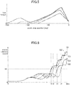
- FIG. 5 shows a relationship between a crank stop position before the engine start control and a loss torque in the engine 2 during the engine start control.
- a horizontal axis shows the crank stop position [deg] and a vertical axis shows the loss torque.
- the loss torque corresponds to a torque required to start the engine 2, i.e., a torque required to rotate the crankshaft of the engine 2.
- each line in FIG. 5 indicates how the loss torque changes according to an advance of the crank position for each of a plurality of specific crank stop positions (-180 deg, -150 deg, -120 deg, -90 deg). In other words, each line in FIG. 5 indicates a locus of the loss torque during the rotation of the crankshaft.
- the solid line graph shows the change of the loss torque when the crank stop position is -180 deg.
- the loss torque as shown in FIG. 5 is defined for each cylinder of the engine 2 (multi-cylinder engine) having a plurality of cylinders. In this case, the sum of the loss torques of all cylinders is the torque required to start the engine 2.
- the torque (loss torque) required to start the engine 2 changes in accordance with the crank stop position before the engine start control. Therefore, the optimum value of the torque (clutch transmission torque) transmitted from the electric motor 4 to the engine 2 via the first clutch CL1 at the time of starting engine 2, that is, the optimum clutch engagement pressure to be applied to the first clutch CL1 at the time of starting engine 2 changes depending on the crank stop position before the engine start control.
- the controller 20 sets the clutch engagement pressure in accordance with the crank stop position before the engine start control in order to efficiently start the engine 2 while ensuring the fuel efficiency at the time of starting the engine 2.
- the controller 20 makes the clutch engagement pressure applied to the first clutch CL1 large, at the crank stop position where the loss torque is high.
- the controller 20 sums up the loss torques of all cylinders, and makes the clutch engagement pressure applied to the first clutch CL1 large, at the crank stop position where the total value is large.
- the optimum clutch engagement pressure (the clutch engagement pressure that can efficiently start the engine 2 while ensuring the fuel efficiency at the time of starting the engine 2) according to the crank stop position is preliminarily obtained by experiments or simulations, so as to create a map in which the optimum clutch engagement pressure is associated with the crank stop position, and the controller 20 reads the clutch engagement pressure according to the crank stop position before the engine start control by using the map, so as to perform the control for applying the read clutch engagement pressure to the first clutch CL1.
- FIG. 6 is an explanatory diagram of a difference in start time of the engine 2 due to a difference in the crank stop positions before the engine start control.
- a horizontal axis shows time
- a vertical axis shows an engine rotation speed.
- graphs G1 to G5 in FIG. 6 show time changes of the engine rotation speed when the engine start control is performed for different crank stop positions.
- the graphs G1, G2, G3, G4 and G5 show the time changes of the engine rotation speed due to the engine start control when the crank stop position is 160 deg, 170 deg, 180 deg, 190 deg, and 200 deg, respectively.
- the time (start time) when the engine 2 is started by the engine start control that is, the time at which the engine rotation speed reaches the predetermined rotation speed N1 changes depending on the difference in the crank stop position.
- the engine 2 is started at time t1 at the crank stop position of the graphs G1 and G2, and the engine 2 is started at time t2 at the crank stop position of the graph G3, and the engine 2 is started at time t3 at the crank stop position of the graph G4, and the engine 2 is started at time t4 at the crank stop position of the graph G5 (t1 ⁇ t2 ⁇ t3 ⁇ t4).
- the start time of the engine 2 changes depending on the crank stop position. This is because, as shown in FIG.
- the loss torque (torque required to start the engine 2) changes depending on the crank stop position.
- the start time of the engine 2 becomes long, at the crank stop position where the loss torque is high.
- the controller 20 obtains the predicted start time and the actual start time as for the start time by the engine start control that changes depending on the crank stop position, and corrects the clutch engagement pressure according to the crank stop position based on the time difference between the predicted start time and the actual start time.
- FIG. 7 is an explanatory diagram of the predicted start time by the engine start control in the present embodiment.
- a horizontal axis shows time
- a vertical axis shows an engine rotation speed.
- FIG. 7 shows an example of time change when it is predicted that the engine 2 starts after time T1 has elapsed from the start of engine start control (i.e., the engine rotation speed reaches the predetermined rotation speed N1), that is, when the time T1 is calculated as the predicted start time.
- the start time of the engine 2 changes in accordance with the crank stop position ( FIG. 6 ), and this is because the loss torque (torque required to start the engine 2) changes in accordance with the crank stop position ( FIG. 5 ).
- the controller 20 calculates the predicted start time based on the crank stop position before the engine start control. Basically, the controller 20 calculates a long predicted start time at the crank stop position where the loss torque is high. When the loss torque is defined for each cylinder as described above, the controller 20 sums up the loss torques of all cylinders, and calculates a long predicted start time at the crank stop position where the total value is large.
- the predicted start time according to the crank stop position is preliminarily obtained by experiments or simulations (i.e., the predicted start time for which the optimum clutch engagement pressure according to the crank stop position is used is preliminarily obtained), so as to create a map in which the predicted start time is associated with the crank stop position, and the controller 20 reads the predicted start time according to the crank stop position before the engine start control by using the map.
- the time change of the engine rotation speed shown in FIG. 7 corresponds to the predicted time change of the engine rotation speed.
- the predicted start time may be calculated directly from the crank stop position.
- FIG. 8 is an explanatory diagram of the actual start time by the engine start control in the present embodiment.
- a horizontal axis shows time
- a vertical axis shows an engine rotation speed.
- FIG. 8 shows such a situation that the engine 2 is actually started after time T2 has elapsed from the start of the engine start control, that is, T2 is obtained as the actual start time.
- the controller 20 obtains the time from the start of performing the engine start control to the time when the engine rotation speed detected by the engine rotation speed sensor SN1 reaches the predetermined speed N1, as the actual start time T2.
- FIG. 9 is an explanatory diagram of a time difference between the predicted start time and the actual start time by the engine start control, in the present embodiment.
- a horizontal axis shows time
- a vertical axis shows an engine rotation speed.
- FIG. 9 is a diagram in which the predicted start time T1 shown in FIG. 7 and the actual start time T2 shown in FIG. 8 are overlapped.
- the controller 20 obtains the time difference T3 between the predicted start time T1 and the actual start time T2, and corrects the clutch engagement pressure applied to the first clutch CL1 at the time of starting the engine 2 next time, based on the said time difference T3.
- the predicted start time T1 is calculated by appropriately taking the crank stop position into consideration.
- the time difference T3 between the predicted start time T1 and the actual start time T2 may occur. It is considered that this is due to the accuracy of the sensors used for the engine start, the assembly accuracy of the engine parts, the secular change and the parts variation. Therefore, in the present embodiment, in order to properly consider such various factors, the time difference T3 between the predicted start time T1 and the actual start time T2 corresponding to the crank stop position is obtained at any time, and the clutch engagement pressure applied to the first clutch CL1 is appropriately corrected according to the time difference T3.
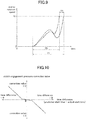
- FIG. 10 shows a correction value of the clutch engagement pressure (clutch engagement pressure correction value) according to the time difference between the predicted start time and the actual start time (predicted start time - actual start time), in the present embodiment.
- a horizontal axis shows the time difference between the predicted start time and the actual start time
- a vertical axis shows the clutch engagement pressure correction value.
- FIG. 10 corresponds to a map of the clutch engagement pressure correction value defined in accordance with the time difference between the predicted start time and the actual start time.
- the clutch engagement pressure correction value is a value for obtaining the clutch engagement pressure which is applied when the engine 2 is started next time.
- the map shown in FIG. 10 defines a negative clutch engagement pressure correction value ( ⁇ 0) in a region where the predicted start time is longer than the actual start time (time difference > 0). Therefore, when the predicted start time is longer than the actual start time, the clutch engagement pressure at the time of starting the engine 2 next time is decreased.
- the map defines a positive clutch engagement pressure correction value (> 0) in a region where the predicted start time is shorter than the actual start time (time difference ⁇ 0). Therefore, when the predicted start time is shorter than the actual start time, the clutch engagement pressure at the time of starting the engine 2 next time is increased.
- the map is defined such that an absolute value of the clutch engagement pressure correction value increases as an absolute value of the time difference between the predicted start time and the actual start time increases. Accordingly, as a deviation of the predicted start time with respect to the actual start time becomes larger, the clutch engagement pressure at the time of starting the engine 2 next time is greatly corrected by the clutch engagement pressure correction value.
- FIG. 11 is a flowchart showing an engine start control process in the present embodiment.
- the engine start control process is repeatedly executed by the controller 20 at a predetermined cycle.
- step S11 the controller 20 obtains the various information of the hybrid vehicle 1, including the information corresponding to the detection signals by the above sensors SN1 to SN5. Then, the controller 20 goes to step S12.
- step S12 the controller 20 determines whether or not the current traveling mode is the first traveling mode (EV traveling mode). For example, the controller 20 makes the determination based on the control signals output to the electric motor 4, the first clutch CL1 and the second clutch CL2. In this example, the controller 20 determines that the current traveling mode is the first traveling mode when the first clutch CL1 is released, the second clutch CL2 is engaged, and the torque is output from the electric motor 4.
- the controller 20 determines that the current traveling mode is the first traveling mode (step S12: Yes)
- the controller 20 goes to step S13.
- step S12: No typically when the current traveling mode is the second traveling mode, the controller 20 ends the engine start control process. In this case, since the engine 2 has been already operated, it is not necessary to start the engine 2 by performing the engine start control.
- step S13 the controller 20 determines whether or not a request for switching from the first traveling mode to the second traveling mode is issued, in other words, whether or not a request for starting the engine 2 is issued.
- the controller 20 determines that the request for switching to the second traveling mode is issued, when the SOC of the battery 5 detected by the SOC sensor SN5 is less than a predetermined value (for example, a lower limit value of the SOC at which the battery 5 should be charged, or the SOC at which the electric power of the battery 5 is prohibited from being taken out, which are defined from the viewpoint of protection of the battery 5).
- a predetermined value for example, a lower limit value of the SOC at which the battery 5 should be charged, or the SOC at which the electric power of the battery 5 is prohibited from being taken out, which are defined from the viewpoint of protection of the battery 5.
- the controller 20 determines that the request for switching to the second traveling mode is issued, when an air conditioner switch of the hybrid vehicle 1 is turned on by the driver.
- the controller 20 determines that the request for switching to the second traveling mode is issued, when a relatively strong request for accelerating is issued by the driver (for example, when the accelerator pedal is greatly depressed by the driver).
- the controller 20 determines that the request for switching from the first traveling mode to the second traveling mode is issued (step S13: Yes)
- the controller 20 goes to step S14.
- the controller 20 determines that the request for switching from the first traveling mode to the second traveling mode is not issued (step S13: No)
- the controller 20 ends the engine start control process. In this case, since the first traveling mode is maintained, it is not necessary to start the engine 2 by performing the engine start control.
- step S14 the controller 20 determines whether or not a request for accelerating is not issued by the driver. Specifically, the controller 20 determines the request for accelerating by determining whether or not the amount of change in the relative position of the accelerator pedal detected by the accelerator position sensor SN3 is equal to or greater than a predetermined amount. As a result, when the controller 20 determines that the request for accelerating is not issued (step S14: Yes), the controller 20 goes to step S15.
- step S15 the controller 20 obtains the crank position (crank stop position) during the engine stop before the engine start control based on the signal from the engine rotation speed sensor SN1 as the crank angle sensor.
- step S16 the controller 20 sets the clutch engagement pressure applied to the first clutch CL1 based on the crank stop position obtained in step S15.
- the controller 20 refers to the preliminarily created map in which the optimum clutch engagement pressure is associated with the crank stop position, and reads the clutch engagement pressure corresponding to the crank stop position obtained in step S15, so as to set the said clutch engagement pressure to the first clutch CL1.
- This map is created by preliminarily obtaining the optimum clutch engagement pressure according to the crank stop position, especially, the clutch engagement pressure that can efficiently start the engine 2 while ensuring the fuel efficiency at the time of starting the engine 2, by the experiments or the simulations.
- the map is defined such that the clutch engagement pressure becomes large at the crank stop position where the loss torque is high.
- step S17 the controller 20 calculates the time (predicted start time) from the start of the engine start control until the engine 2 is started by the engine start control, based on the crank stop position obtained in step S15.
- the controller 20 refers to the preliminarily created map in which the predicted start time is associated with the crank stop position, and obtains the predicted start time corresponding to the crank stop position obtained in step S15.
- This map is created by preliminarily obtaining the predicted start time according to the crank stop position, especially, the predicted start time acquired when the optimum clutch engagement pressure (i.e., the clutch engagement pressure that can efficiently start the engine 2 while ensuring the fuel efficiency at the time of starting the engine 2) according to the crank stop position is applied, by the experiments or the simulations.
- the map is defied such that the predicted start time becomes long at the crank stop position where the loss torque is high.
- the above process in step S17 may be performed after the start of the engine start control in step S18 described below.
- step S18 the controller 20 performs the engine start control for starting (restarting) the engine 2. Specifically, the controller 20 performs the control to apply the clutch engagement pressure set in step S16 to the first clutch CL1 so as to change the first clutch CL1 from the disengaged state to the engaged state, and performs the control to crank the engine 2 by the torque of the electric motor 4.
- step S19 the controller 20 obtains the time (actual start time) from the start of the engine start control until the engine 2 is actually started by the engine start control. Specifically, the controller 20 obtains the time from the start of performing the engine start control, to the time when the engine rotation speed detected by the engine rotation speed sensor SN1 reaches the predetermined rotation speed N1, as the actual start time.
- step S20 the controller 20 corrects the clutch engagement pressure applied at the time of staring the engine 2 next time, based on the time difference between the predicted start time calculated in step S17 and the actual start time obtained in step S19.
- the controller 20 refers to the preliminarily created map in which the clutch engagement pressure correction value is associated with the time difference between the predicted start time and the actual start time ( FIG. 10 ), and reads the clutch engagement pressure correction value corresponding to the time difference between the predicted start time calculated in step S17 and the actual start time obtained in step S19. Then, the controller 20 corrects the clutch engagement pressure which is used at the time of staring the engine 2 next time, based on the clutch engagement pressure correction value.
- the controller 20 uses the negative clutch engagement pressure correction value so as to decrease the clutch engagement pressure at the time of staring the engine 2 next time.
- the controller 20 uses the positive clutch engagement pressure correction value so as to increase the clutch engagement pressure at the time of staring the engine 2 next time.
- the controller 20 makes the clutch engagement pressure correction value (absolute value) larger as the time difference (absolute value) between the predicted start time and the actual start time becomes larger, so as to greatly correct the clutch engagement pressure which is used at the time of staring the engine 2 next time.
- the controller 20 ends the engine start control process.
- the clutch engagement pressure corrected in the above-mentioned way is used when the clutch engagement pressure is set in step S16 in the next engine start control process. Specifically, as described above, since the clutch engagement pressure is obtained by using the map defined in accordance with the crank stop position, the correction by the clutch engagement pressure correction value may be applied to the map. On the other hand, since the predicted start time is calculated based on the crank stop position (step S17), the predicted start time may also be corrected in accordance with the correction of the clutch engagement pressure by the clutch engagement pressure correction value. In particular, the map in which the predicted start time is associated with the crank stop position may be corrected in accordance with the clutch engagement pressure correction value. Therefore, the time difference between the predicted start time and the actual start time which is calculated in the future will be decreased.
- step S14 when the controller 20 determines in step S14 that the request for accelerating is issued by the driver (step S14: No), the controller 20 goes to step S21.
- step S21 the controller 20 sets the clutch engagement pressure used for the acceleration (clutch engagement pressure for acceleration) to the first clutch CL1 and performs the engine start control.
- the controller 20 uses the clutch engagement pressure for acceleration which is larger than the above clutch engagement pressure according to the crank stop position (i.e., the clutch engagement pressure that can efficiently start the engine 2 while ensuring the fuel efficiency at the time of starting the engine 2).
- the clutch engagement pressure for acceleration is a clutch engagement pressure that is effective for promptly starting the engine 2 in order to appropriately satisfy the acceleration request from the driver, and is defined by experiments or simulations in advance.
- the controller 20 performs the control to apply the above clutch engagement pressure for acceleration to the first clutch CL1 and performs the control to crank the engine 2 by the torque of the electric motor 4, in order to start the engine 2. After step S21, the controller 20 ends the engine start control process.
- the controller 20 when the controller 20 starts the engine 2 in order to switch the traveling mode of the hybrid vehicle 1 from the first traveling mode to the second traveling mode, the controller 20 obtains the predicted start time and the actual start time by the engine start control, and corrects the clutch engagement pressure so as to decrease the clutch engagement pressure applied to the first clutch CL1 at the time of staring the engine 2 next time, when the actual start time is shorter than the predicted start time.
- the controller 20 calculates the predicted start time in consideration of various states, and corrects the clutch engagement pressure applied to the first clutch CL1 by the learning according to the time difference between the predicted start time and the actual start time, specifically, corrects the clutch engagement pressure to decrease the said pressure when the actual start time is shorter than the predicted start time. Therefore, it is possible to optimize the clutch engagement pressure used for starting the engine 2 at the time of switching from the first travel mode to the second travel mode, thereby suppressing the deterioration of the fuel efficiency due to the application of the clutch engagement pressure more than necessary.
- the controller 20 calculates the predicted start time based on the crank position (crank stop position) during the engine stop before the switch from the first travel mode to the second travel mode.
- the start time of the engine 2 greatly changes depending on the crank stop position (see FIG. 6 ). This is because the torque (loss torque) required to start the engine 2 changes depending on the crank stop position (see FIG. 5 ). Therefore, in the present embodiment, the controller 20 calculates the predicted start time in consideration of the above change of the start time depending on the crank stop position. Therefore, it is possible to appropriately calculate the predicted start time in which the influence of the crank stop position is taken into consideration, in other words, the predicted start time can be obtained with high accuracy.
- the controller 20 when the request for accelerating the hybrid vehicle 1 is issued by the driver at the time of switching from the first traveling mode to the second traveling mode, the controller 20 makes the clutch engagement pressure applied to the first clutch CL1 larger than when the request is not issued. Therefore, the quick start of the engine 2 can be appropriately prioritized. In other words, by starting the engine 2 quickly, the acceleration request from the driver can be appropriately realized.
- the controller 20 makes the decreased amount (absolute value) of the clutch engagement pressure by the correction, as the difference (absolute value) between the actual start time and the predicted start time becomes larger. Therefore, the clutch engagement pressure can be effectively optimized.
- the controller 20 determines that the engine start ends when the engine rotation speed reaches the predetermined rotation speed N1, and obtains the predicted start time and the actual start time. Therefore, the accuracy of the predicted start time and the actual start time can be appropriately ensured.
Abstract
Description
- The present invention relates to a hybrid vehicle control system comprising an engine, an electric motor and a clutch configured to switch between a transmission of torque between the engine and the electric motor, and a non-transmission of the torque.
- Heretofore, in a hybrid vehicle which includes an engine and an electric motor as a power source and which is driven by at least one of a driving force of the engine and a driving force of the electric motor, there has been provided a technique in which the engine is cranked by the electric motor to start the engine.
- For example, Patent Document 1 (Japanese Laid-Open Patent Publication
2012-86662 A - In the meanwhile, the hybrid vehicle, which includes the clutch for switching between the transmission of the torque between the engine and the electric motor and the non-transmission of the torque, comprises a traveling mode (hereinafter referred to as "first traveling mode") in which the clutch is set to a disengaged state and the hybrid vehicle travels by using the torque of the electric motor without using the torque of the engine, and a traveling mode (hereinafter referred to as "second traveling mode") in which the clutch is set to an engaged state and the hybrid vehicle travels by using at least the torque of the engine. The hybrid vehicle starts the engine by applying an engagement pressure (hereinafter referred to as "clutch engagement pressure") to the clutch so as to change the clutch from the disengaged state to the engaged state, and by cranking the engine by the electric motor, when the traveling mode of the hybrid vehicle is switched from the first traveling mode to the second traveling mode.
- When the engine is started in order to switch the traveling mode from the first traveling mode to the second traveling mode as described above, it is desirable to apply an appropriate engagement pressure to the clutch. This is because it takes a long time to start the engine (the engine may not start in some cases) if the clutch engagement pressure is too low, while a fuel efficiency deteriorates due to a wasteful consumption of energy if the clutch engagement pressure is too high. That is, there is an optimum clutch engagement pressure for properly starting the engine.
- It is thought that the optimum clutch engagement pressure varies depending on a crank position during the engine stop before the engine start, accuracy of the sensors used for the engine start, assembly accuracy of engine parts, a secular change and parts variation. Therefore, it is difficult to accurately obtain the optimum clutch engagement pressure. Accordingly, the conventional techniques prioritize the engine start by applying the clutch engagement pressure that is considered to be sufficient to start the engine (in other words, the clutch engagement pressure that is higher than the optimum engagement pressure), without obtaining the optimum clutch engagement pressure. As a result, the above deterioration of the fuel efficiency occurs due to the application of unnecessarily high clutch engagement pressure.
- The present invention has been made to solve the above conventional problem, and an object thereof is to provide a hybrid vehicle control system capable of applying an appropriate engagement pressure to a clutch provided between an engine and an electric motor, when the engine is started in order to switch from a traveling mode using the electric motor to a traveling mode using the engine.
- In order to achieve the above object, the present invention provides a hybrid vehicle control system, which is applied to a hybrid vehicle including an engine, an electric motor and a clutch configured to switch between a transmission of torque between the engine and the electric motor, and a non-transmission of the torque, wherein the hybrid vehicle control system includes: a traveling mode determining means for determining whether or not to switch a traveling mode of the hybrid vehicle from a first traveling mode in which the clutch is set to a disengaged state and the hybrid vehicle travels by using torque of the electric motor without using torque of the engine, to a second traveling mode in which the clutch is set to an engaged state and the hybrid vehicle travels by using at least the torque of the engine; an engine start controlling means for performing a control for an engine start by applying an engagement pressure to the clutch so as to change the clutch from the disengaged state to the engaged state, and by cranking the engine by the motor, when the traveling mode determining means determines to switch the traveling mode of the hybrid vehicle from the first traveling mode to the second traveling mode; a predicted start time calculating means for calculating a predicted start time from a start of the control for the engine start by the engine start controlling means to an end of the engine start; an actual start time obtaining means for obtaining an actual start time from the start of the control for the engine start by the engine start controlling means to an actual end of the engine start; and an engagement pressure correcting means for correcting the engagement pressure so as to decrease the engagement pressure which is applied to the clutch at the time of performing the control for the engine start by the engine start controlling means next time, when the actual start time obtained by the actual start time obtaining means is shorter than the predicted start time predicted by the predicted start time calculating means.
- In the present invention, when the engine is started in order to switch the traveling mode of the hybrid vehicle from the first traveling mode to the second traveling mode, the hybrid vehicle control system obtains the predicted start time and the actual start time by the engine start controlling means, and corrects the clutch engagement pressure so as to decrease the clutch engagement pressure applied to the clutch at the time of staring the engine next time, when the actual start time is shorter than the predicted start time. In other words, the hybrid vehicle control system calculates the predicted start time in consideration of various states, and corrects the clutch engagement pressure applied to the clutch by learning, in accordance with a time difference between the predicted start time and the actual start time, specifically, corrects the clutch engagement pressure to decrease the said pressure when the actual start time is shorter than the predicted start time. Therefore, it is possible to optimize the clutch engagement pressure used for starting the engine at the time of switching from the first travel mode to the second travel mode, thereby suppressing deterioration of fuel efficiency due to an application of the clutch engagement pressure more than necessary.
- Preferably, in the hybrid vehicle control system of the present invention, the predicted start time calculating means is configured to calculate the predicted start time based on a crank position during an engine stop before the control for the engine start by the engine start controlling means.
- A start time of the engine greatly changes depending on a crank position (crank stop position) during the engine stop before the switch from the first travel mode to the second travel mode. This is because a torque (loss torque) required to start the engine changes depending on the crank stop position. Therefore, in the present invention, the predicted start time calculating means calculates the predicted start time in consideration of the above change of the start time depending on the crank stop position. Therefore, it is possible to appropriately calculate the predicted start time in which an influence of the crank stop position is taken into consideration. Hence, the predicted start time can be obtained with high accuracy.
- Preferably, in the hybrid vehicle control system of the present invention, when a request for accelerating the hybrid vehicle is issued by a driver, the engine start controlling means is configured to make the engagement pressure applied to the clutch larger than when the request for accelerating the hybrid vehicle is not issued by the driver, in order to shorten a start time of the engine, under the condition that the traveling mode determining means determines to switch the traveling mode of the hybrid vehicle from the first traveling mode to the second traveling mode.
- According to the above present invention, when the request for accelerating is issued by the driver, a quick start of the engine can be appropriately prioritized. In other words, by starting the engine quickly, an acceleration request from the driver can be appropriately realized.
- Preferably, in the hybrid vehicle control system of the present invention, the engagement pressure correcting means is configured to correct the engagement pressure so as to make a decreased amount of the engagement pressure larger, as an absolute value of a difference between the actual start time and the predicted start time becomes larger.
- According to the above present invention, the clutch engagement pressure can be effectively optimized.
- Preferably, in the hybrid vehicle control system of the present invention, when an engine rotation speed reaches a given value, the predicted start time calculating means and the actual start time obtaining means are configured to determine that the engine start ends, and to calculate the predicted start time and obtain the actual start time, respectively.
- According to the above present invention, the predicted start time calculating means and the actual start time obtaining means respectively obtains the predicted start time and the actual start time by using a timing when the engine rotation speed reaches the given value, as a timing when the engine start ends. Therefore, the accuracy of the predicted start time and the actual start time can be appropriately ensured.
- The above hybrid vehicle control system of the present invention can apply an appropriate engagement pressure to a clutch provided between an engine and an electric motor, when the engine is started in order to switch from a traveling mode using the electric motor to a traveling mode using the engine.
-
-
FIG. 1 is a schematic diagram depicting a configuration of a hybrid vehicle employing a hybrid vehicle control system in an embodiment of the present invention. -
FIG. 2 is a block diagram depicting an electrical configuration of the hybrid vehicle control system in the present embodiment. -
FIG. 3 is an explanatory diagram of an outline of a correction of a clutch engagement pressure in the present embodiment. -
FIG. 4 shows an example of the clutch engagement pressure applied to a first clutch during an engine start control, in the present embodiment. -
FIG. 5 is an explanatory diagram of a relationship between a crank stop position before the engine start control and a loss torque during the engine start control. -
FIG. 6 is an explanatory diagram of a difference in a start time of the engine due to a difference in the crank stop positions before the engine start control. -
FIG. 7 is an explanatory diagram of a predicted start time by the engine start control in the present embodiment. -
FIG. 8 is an explanatory diagram of an actual start time by the engine start control in the present embodiment. -
FIG. 9 is an explanatory diagram of a time difference between the predicted start time and the actual start time by the engine start control, in the present embodiment. -
FIG. 10 is an explanatory diagram of a clutch engagement pressure correction value according to the time difference between the predicted start time and the actual start time, in the present embodiment. -
FIG. 11 is a flowchart showing an engine start control process in the present embodiment. - With reference to the accompanying drawings, a hybrid vehicle control system in one embodiment of the present invention will now be described.
-
FIG. 1 is a schematic diagram depicting a configuration of a hybrid vehicle employing a hybrid vehicle control system in an embodiment of the present invention. - As shown in
FIG. 1 , thehybrid vehicle 1 comprises: an engine 2 (for example, a gasoline engine) which generates a torque for driving thehybrid vehicle 1; anelectric motor 4 which is provided downstream side of theengine 2 on a driving force transmitting path of thehybrid vehicle 1, and which generates a torque for driving thehybrid vehicle 1; a battery 5 which exchanges an electric power with theelectric motor 4 via an inverter (not shown): atransmission 6 which is provided on the downstream side of theelectric motor 4 on the driving force transmitting path of thehybrid vehicle 1, and which changes rotation speed of theengine 2 and/or theelectric motor 4; a drivingforce transmitting system 8 which transmits the torque from thetransmission 6 to the downstream side; adrive shaft 10 which drivesdrive wheels 12 by the torque from the drivingforce transmitting system 8; and thedrive wheels 12. - An output shaft of the
engine 2 and a rotation shaft of theelectric motor 4 are coaxially connected by a shaft AX1 via a first clutch CL1. By the first clutch CL1, it is possible to switch between a transmission of the torque between theengine 2 and theelectric motor 4, and a non-transmission of the said torque. For example, the first clutch CL1 is configured by a dry multi-plate clutch capable of changing a transmission torque capacity by continuously or stepwisely controlling a clutch operating oil flow rate and a clutch operating oil pressure by using a motor (not shown). - The rotation shaft of the
electric motor 4 and a rotation shaft of thetransmission 6 are coaxially connected by a shaft AX2. Typically, thetransmission 6 has one or more planetary gears provided therein, and corresponds to an automatic transmission which has a function of automatically switching gear stages (gear ratios) in accordance with a vehicle speed and an engine rotation speed. Further, thetransmission 6 is provided with a second clutch CL2, and the second clutch CL2 can switch between a transmission of a torque between the upstream side of the transmission 6 (theengine 2 and the electric motor 4) and the downstream side of the transmission 6 (the drive wheels 12), and a non-transmission of the said torque. For example, the second clutch CL2 is also configured by the dry multi-plate clutch capable of changing the transmission torque capacity by continuously or stepwisely controlling the clutch operating oil flow rate and the clutch operating oil pressure by using the motor (not shown). Actually, the second clutch CL2 is configured by a number of clutches used to switch various gear stages in thetransmission 6. - The torque is input to the driving
force transmitting system 8 via an output shaft AX3 of thetransmission 6. The drivingforce transmitting system 8 includes a differential gear which distributes the driving force to a pair ofdriving wheels 12, and a final gear. - The
above hybrid vehicle 1 can switch a traveling mode by switching between an engagement and a disengagement of the first clutch CL1. Thehybrid vehicle 1 comprises a first traveling mode in which the first clutch CL1 is set to a disengaged state and thehybrid vehicle 1 travels by using the torque of theelectric motor 4 without using the torque of theengine 2, and a second traveling mode in which the first clutch CL1 is set to an engaged state and thehybrid vehicle 1 travels by using at least the torque of theengine 2. The first traveling mode is a so-called EV traveling mode. The second traveling mode is an engine traveling mode using only the torque of theengine 2, or a hybrid traveling mode using both the torque of theengine 2 and the torque of theelectric motor 4. The second clutch CL2 is basically set to the engaged state in both the first traveling mode and the second traveling mode, but is set to the disengaged state (specifically, a ship state) at the time of switching between the first traveling mode and the second traveling mode. - Next,
FIG. 2 is a block diagram depicting an electrical configuration of the hybrid vehicle control system in this embodiment. - As shown in
FIG. 2 , acontroller 20 receives various input signals as follows: a signal from an engine rotationspeed sensor SN 1 for detecting an engine rotation speed of theengine 2; a signal from a motor rotation speed sensor SN2 for detecting a motor rotation speed of theelectric motor 4; a signal from an accelerator position sensor SN3 for detecting a relative position of an accelerator pedal which corresponds to a degree of depression of the accelerator pedal; a signal for a vehicle speed sensor SN4 for detecting a vehicle speed of thehybrid vehicle 1; and a signal from a SOC sensor SN5 for detecting a state of charge (SOC) of the battery 5. Specifically, the engine rotation speed sensor SN1 is configured by a crank angle sensor for detecting a crank position (crank angle) of a crankshaft in theengine 2. - The
controller 20 is a controller comprised of a circuitry and based on a well-known microcomputer, and comprises: a microprocessor serving as a central processing unit (CPU) for executing a program; a memory composed of, e.g., a random access memory (RAM) and a read only memory (ROM) and capable of storing therein a program and data; and an input-output bus for inputting and outputting electric signals. Thecontroller 20 corresponds to the "hybrid vehicle control system" in the present invention. - In particular, the
controller 20 provides control signals to theengine 2, theelectric motor 4, the first clutch CL1 and the second clutch CL2 to control them, based on the detected signal by the above sensors SN1 to SN5. For example, thecontroller 20 performs a control for adjusting an ignition timing, a fuel injection timing and a fuel injection amount, and a control for adjusting a rotation speed and a torque of theelectric motor 4, and a control for switching between the engagement and disengagement of the first and second clutches CL1, CL2 (including a control for adjusting the engagement pressure (clutch engagement pressure) applied to the first and second clutches CL1. CL2). Actually, thecontroller 20 controls an ignition plug, a fuel injector and a throttle valve in theengine 2, and controls theelectric motor 4 via the inverter, and control the first and second clutches CL1, CL2 via a hydraulic control circuit. - Further, in the present embodiment, the
controller 20 comprises a travelingmode determining part 20a, an enginestart controlling part 20b, a predicted starttime calculating part 20c, an actual starttime obtaining part 20d and an engagementpressure correcting part 20e, as functional components. The travelingmode determining part 20a determines whether or not to switch the traveling mode of thehybrid vehicle 1 from the first traveling mode to the second traveling mode, based on the detected signals by the above sensors SN1 to SN5. The engine start controllingpart 20b perform a control for an engine start by applying the engagement pressure to the first clutch CL1 so as to change the first clutch CL1 from the disengaged state to the engaged state, and by cranking theengine 2 by theelectric motor 4, when the travelingmode determining part 20a determines to switch the traveling mode of thehybrid vehicle 1 from the first traveling mode to the second traveling mode. Hereinafter, the above control for the engine start is referred to as "engine start control". - The predicted start
time calculating part 20c predicts, based on the crank position during the engine stop before the engine start control, the time from the start of the engine start control until theengine 2 is started by the engine start control (i.e., the predicted starttime calculating part 20c calculates the predicted start time). The actual starttime obtaining part 20d obtains, based on the detected signal by the engine rotation speed sensor SN1, the time from the start of the engine start control until theengine 2 is actually started by the engine start control (i.e., the actual starttime obtaining part 20d obtains the actual start time). The engagementpressure correcting part 20e corrects the engagement pressure (clutch engagement pressure) which is applied to the clutch at the time of performing the engine start control by the engine start controllingpart 20b next time, based on the time difference between the actual start time and the predicted start time. In other words, the engagementpressure correcting part 20e learns the clutch engagement pressure of the first clutch CL1 based on the time difference. Typically, the engagementpressure correcting part 20e corrects the clutch engagement pressure so as to decrease the clutch engagement pressure at the time of starting theengine 2 next time, when the actual start time is shorter than the predicted start time. - Next, the control content performed by the
controller 20 in the present embodiment will be described. In the present embodiment, when theengine 2 starts in order to switch the traveling mode of thehybrid vehicle 1 from the first traveling mode to the second traveling mode, thecontroller 20 performs the control for applying a predetermined engagement pressure (clutch engagement pressure) to the first clutch CL1 so as to change the first clutch CL1 from the disengaged state to the engaged state. Specifically, in the present embodiment, thecontroller 20 corrects the clutch engagement pressure by the learning, so as to apply an optimum clutch engagement pressure to the first clutch CL1. - First, an outline of the correction of the clutch engagement pressure in the present embodiment will be described with reference to
FIG. 3 . InFIG. 3 , a horizontal axis shows time, and a vertical axis shows an engine rotation speed. Specifically,FIG. 3 shows an example of time change of the engine rotation speed when the engine start control is performed in order to switch the traveling mode of thehybrid vehicle 1 from the first traveling mode to the second traveling mode. - In the present embodiment, as shown in
FIG. 3 , thecontroller 20 obtains the predicted start time and the actual start time by the engine start control, and then corrects the clutch engagement pressure of the first clutch CL1 at the time of starting theengine 2, based on the time difference between the actual start time and the predicted start time. Specifically, thecontroller 20 corrects (learns) the clutch engagement pressure by a feedback control based on the magnitude of the time difference between the actual start time and the predicted start time. The reason for correcting the clutch engagement pressure in this way is as follows. - When the
engine 2 is started in order to switch the traveling mode from the first traveling mode to the second traveling mode, it is desirable to apply an appropriate engagement pressure to the first clutch CL1. This is because it takes a long time to start the engine 2 (theengine 2 may not start in some cases) if the clutch engagement pressure is too low, while a fuel efficiency deteriorates due to a wasteful consumption of energy if the clutch engagement pressure is too high. That is, there is an optimum clutch engagement pressure for properly starting theengine 2. It is thought that the optimum clutch engagement pressure varies depending on the crank position (crank stop position) during the engine stop before the engine start, accuracy of the sensors used for the engine start, assembly accuracy of engine parts, a secular change and parts variation. Therefore, it is difficult to accurately obtain the optimum clutch engagement pressure. Accordingly, the conventional techniques prioritize the engine start by applying the clutch engagement pressure that is considered to be sufficient to start the engine 2 (in other words, the clutch engagement pressure that is higher than the optimum engagement pressure), without obtaining the optimum clutch engagement pressure. As a result, the above deterioration of the fuel efficiency occurs due to the application of unnecessarily high clutch engagement pressure. - Accordingly, in the present embodiment, in order to suppress the deterioration of the fuel efficiency, the
controller 20 corrects the clutch engagement pressure by the learning, so as to optimize the clutch engagement pressure applied to the first clutch CL1. Specifically, thecontroller 20 corrects the clutch engagement pressure which is applied when theengine 2 starts next time, based on the time difference between the predicted start time and the actual start time by the engine start control. As shown inFIG. 3 , thecontroller 20 uses the timing at which the engine rotation speed reaches a predetermined rotation speed N1, as the timing at which the start of theengine 2 ends, in order to obtain the predicted start time and the actual start time. In consideration of the characteristic that the detection accuracy of the engine rotation speed sensor SN1 is difficult to be ensured in the low speed range, the rotation speed at which the detection accuracy of the engine rotation speed sensor SN1 can be ensured is applied to the predetermined rotation speed N1. For example, about 400 to 600 rpm is applied to the predetermined rotation speed N1. - Next, with reference to
FIGS. 4 to 10 , the control of the clutch engagement pressure in the present embodiment will be described in detail. - First,
FIG. 4 shows an example of the clutch engagement pressure applied to the first clutch CL1 during the engine start control, in the present embodiment. InFIG. 4 , a horizontal axis shows time, and a vertical axis shows a clutch engagement pressure. The clutch engagement pressure corresponds to a torque (clutch transmission torque) transmitted from theelectric motor 4 to theengine 2 via the first clutch CL1 when theengine 2 is started. As shown inFIG. 4 , in the present embodiment, thecontroller 20 rapidly increases the clutch engagement pressure at the start of the engine start control, and then gradually increases the clutch engagement pressure. The control of the clutch engagement pressure is performed in order to ensure a quick start of theengine 2 by quickly applying the clutch engagement pressure to the first clutch CL1 first, and in order to ensure the detection accuracy of the engine rotation speed sensor SN1 when the clutch engagement pressure is being gradually increased, i.e., in order to obtain the accurate engine rotation speed based on the signal from the engine rotation speed sensor SN1 (the engine rotation speed is used for obtaining the actual start time by the engine start control). - Next,
FIG. 5 shows a relationship between a crank stop position before the engine start control and a loss torque in theengine 2 during the engine start control. InFIG. 5 , a horizontal axis shows the crank stop position [deg] and a vertical axis shows the loss torque. The loss torque corresponds to a torque required to start theengine 2, i.e., a torque required to rotate the crankshaft of theengine 2. Further, each line inFIG. 5 indicates how the loss torque changes according to an advance of the crank position for each of a plurality of specific crank stop positions (-180 deg, -150 deg, -120 deg, -90 deg). In other words, each line inFIG. 5 indicates a locus of the loss torque during the rotation of the crankshaft. For example, the solid line graph shows the change of the loss torque when the crank stop position is -180 deg. In a typical example, the loss torque as shown inFIG. 5 is defined for each cylinder of the engine 2 (multi-cylinder engine) having a plurality of cylinders. In this case, the sum of the loss torques of all cylinders is the torque required to start theengine 2. - As shown in
FIG. 5 , it can be seen that the torque (loss torque) required to start theengine 2 changes in accordance with the crank stop position before the engine start control. Therefore, the optimum value of the torque (clutch transmission torque) transmitted from theelectric motor 4 to theengine 2 via the first clutch CL1 at the time of startingengine 2, that is, the optimum clutch engagement pressure to be applied to the first clutch CL1 at the time of startingengine 2 changes depending on the crank stop position before the engine start control. - Therefore, in the present embodiment, the
controller 20 sets the clutch engagement pressure in accordance with the crank stop position before the engine start control in order to efficiently start theengine 2 while ensuring the fuel efficiency at the time of starting theengine 2. Basically, thecontroller 20 makes the clutch engagement pressure applied to the first clutch CL1 large, at the crank stop position where the loss torque is high. When the loss torque is defined for each cylinder as described above, thecontroller 20 sums up the loss torques of all cylinders, and makes the clutch engagement pressure applied to the first clutch CL1 large, at the crank stop position where the total value is large. In a typical example, the optimum clutch engagement pressure (the clutch engagement pressure that can efficiently start theengine 2 while ensuring the fuel efficiency at the time of starting the engine 2) according to the crank stop position is preliminarily obtained by experiments or simulations, so as to create a map in which the optimum clutch engagement pressure is associated with the crank stop position, and thecontroller 20 reads the clutch engagement pressure according to the crank stop position before the engine start control by using the map, so as to perform the control for applying the read clutch engagement pressure to the first clutch CL1. - Next,
FIG. 6 is an explanatory diagram of a difference in start time of theengine 2 due to a difference in the crank stop positions before the engine start control. InFIG. 6 , a horizontal axis shows time, and a vertical axis shows an engine rotation speed. Specifically, graphs G1 to G5 inFIG. 6 show time changes of the engine rotation speed when the engine start control is performed for different crank stop positions. For example, the graphs G1, G2, G3, G4 and G5 show the time changes of the engine rotation speed due to the engine start control when the crank stop position is 160 deg, 170 deg, 180 deg, 190 deg, and 200 deg, respectively. - As shown in
FIG. 6 , it can be seen that the time (start time) when theengine 2 is started by the engine start control, that is, the time at which the engine rotation speed reaches the predetermined rotation speed N1 changes depending on the difference in the crank stop position. Specifically, theengine 2 is started at time t1 at the crank stop position of the graphs G1 and G2, and theengine 2 is started at time t2 at the crank stop position of the graph G3, and theengine 2 is started at time t3 at the crank stop position of the graph G4, and theengine 2 is started at time t4 at the crank stop position of the graph G5 (t1 <t2<t3<t4). Thus, the start time of theengine 2 changes depending on the crank stop position. This is because, as shown inFIG. 5 , the loss torque (torque required to start the engine 2) changes depending on the crank stop position. The start time of theengine 2 becomes long, at the crank stop position where the loss torque is high. In the present embodiment, thecontroller 20 obtains the predicted start time and the actual start time as for the start time by the engine start control that changes depending on the crank stop position, and corrects the clutch engagement pressure according to the crank stop position based on the time difference between the predicted start time and the actual start time. - Next,
FIG. 7 is an explanatory diagram of the predicted start time by the engine start control in the present embodiment. InFIG. 7 , a horizontal axis shows time, and a vertical axis shows an engine rotation speed. Specifically,FIG. 7 shows an example of time change when it is predicted that theengine 2 starts after time T1 has elapsed from the start of engine start control (i.e., the engine rotation speed reaches the predetermined rotation speed N1), that is, when the time T1 is calculated as the predicted start time. As described above, the start time of theengine 2 changes in accordance with the crank stop position (FIG. 6 ), and this is because the loss torque (torque required to start the engine 2) changes in accordance with the crank stop position (FIG. 5 ). - Therefore, in the present embodiment, the
controller 20 calculates the predicted start time based on the crank stop position before the engine start control. Basically, thecontroller 20 calculates a long predicted start time at the crank stop position where the loss torque is high. When the loss torque is defined for each cylinder as described above, thecontroller 20 sums up the loss torques of all cylinders, and calculates a long predicted start time at the crank stop position where the total value is large. In a typical example, the predicted start time according to the crank stop position is preliminarily obtained by experiments or simulations (i.e., the predicted start time for which the optimum clutch engagement pressure according to the crank stop position is used is preliminarily obtained), so as to create a map in which the predicted start time is associated with the crank stop position, and thecontroller 20 reads the predicted start time according to the crank stop position before the engine start control by using the map. - The time change of the engine rotation speed shown in
FIG. 7 corresponds to the predicted time change of the engine rotation speed. When the above predicted start time is calculated, it is not necessary to predict the time change of the engine speed as shown inFIG. 7 , and the predicted start time may be calculated directly from the crank stop position. - Next,
FIG. 8 is an explanatory diagram of the actual start time by the engine start control in the present embodiment. InFIG. 8 , a horizontal axis shows time, and a vertical axis shows an engine rotation speed. Specifically,FIG. 8 shows such a situation that theengine 2 is actually started after time T2 has elapsed from the start of the engine start control, that is, T2 is obtained as the actual start time. In the present embodiment, thecontroller 20 obtains the time from the start of performing the engine start control to the time when the engine rotation speed detected by the engine rotation speed sensor SN1 reaches the predetermined speed N1, as the actual start time T2. - Next,
FIG. 9 is an explanatory diagram of a time difference between the predicted start time and the actual start time by the engine start control, in the present embodiment. InFIG. 9 , a horizontal axis shows time, and a vertical axis shows an engine rotation speed. Specifically,FIG. 9 is a diagram in which the predicted start time T1 shown inFIG. 7 and the actual start time T2 shown inFIG. 8 are overlapped. As shown inFIG. 9 , thecontroller 20 obtains the time difference T3 between the predicted start time T1 and the actual start time T2, and corrects the clutch engagement pressure applied to the first clutch CL1 at the time of starting theengine 2 next time, based on the said time difference T3. - In the present embodiment, since the start time of the
engine 2 changes depending on the crank stop position, the predicted start time T1 is calculated by appropriately taking the crank stop position into consideration. However, even though the predicted start time T1 is calculated in this way, the time difference T3 between the predicted start time T1 and the actual start time T2 may occur. It is considered that this is due to the accuracy of the sensors used for the engine start, the assembly accuracy of the engine parts, the secular change and the parts variation. Therefore, in the present embodiment, in order to properly consider such various factors, the time difference T3 between the predicted start time T1 and the actual start time T2 corresponding to the crank stop position is obtained at any time, and the clutch engagement pressure applied to the first clutch CL1 is appropriately corrected according to the time difference T3. - Next,
FIG. 10 shows a correction value of the clutch engagement pressure (clutch engagement pressure correction value) according to the time difference between the predicted start time and the actual start time (predicted start time - actual start time), in the present embodiment. InFIG. 10 , a horizontal axis shows the time difference between the predicted start time and the actual start time, and a vertical axis shows the clutch engagement pressure correction value.FIG. 10 corresponds to a map of the clutch engagement pressure correction value defined in accordance with the time difference between the predicted start time and the actual start time. The clutch engagement pressure correction value is a value for obtaining the clutch engagement pressure which is applied when theengine 2 is started next time. - The map shown in
FIG. 10 defines a negative clutch engagement pressure correction value (< 0) in a region where the predicted start time is longer than the actual start time (time difference > 0). Therefore, when the predicted start time is longer than the actual start time, the clutch engagement pressure at the time of starting theengine 2 next time is decreased. On the other hand, the map defines a positive clutch engagement pressure correction value (> 0) in a region where the predicted start time is shorter than the actual start time (time difference < 0). Therefore, when the predicted start time is shorter than the actual start time, the clutch engagement pressure at the time of starting theengine 2 next time is increased. Further, in both the region where the predicted start time is longer than the actual start time and the region where the predicted start time is shorter than the actual start time, the map is defined such that an absolute value of the clutch engagement pressure correction value increases as an absolute value of the time difference between the predicted start time and the actual start time increases. Accordingly, as a deviation of the predicted start time with respect to the actual start time becomes larger, the clutch engagement pressure at the time of starting theengine 2 next time is greatly corrected by the clutch engagement pressure correction value. - Next, with reference to
FIG. 11 , a specific process performed in the engine start control (including the above-mentioned clutch engagement pressure control) in the present embodiment will be described.FIG. 11 is a flowchart showing an engine start control process in the present embodiment. The engine start control process is repeatedly executed by thecontroller 20 at a predetermined cycle. - First, when the engine start control process shown in
FIG. 11 is started, in step S11, thecontroller 20 obtains the various information of thehybrid vehicle 1, including the information corresponding to the detection signals by the above sensors SN1 to SN5. Then, thecontroller 20 goes to step S12. - In step S12, the
controller 20 determines whether or not the current traveling mode is the first traveling mode (EV traveling mode). For example, thecontroller 20 makes the determination based on the control signals output to theelectric motor 4, the first clutch CL1 and the second clutch CL2. In this example, thecontroller 20 determines that the current traveling mode is the first traveling mode when the first clutch CL1 is released, the second clutch CL2 is engaged, and the torque is output from theelectric motor 4. When thecontroller 20 determines that the current traveling mode is the first traveling mode (step S12: Yes), thecontroller 20 goes to step S13. On the other hand, when thecontroller 20 determines that the current traveling mode is not the first traveling mode (step S12: No), typically when the current traveling mode is the second traveling mode, thecontroller 20 ends the engine start control process. In this case, since theengine 2 has been already operated, it is not necessary to start theengine 2 by performing the engine start control. - In step S13, the
controller 20 determines whether or not a request for switching from the first traveling mode to the second traveling mode is issued, in other words, whether or not a request for starting theengine 2 is issued. As one example, thecontroller 20 determines that the request for switching to the second traveling mode is issued, when the SOC of the battery 5 detected by the SOC sensor SN5 is less than a predetermined value (for example, a lower limit value of the SOC at which the battery 5 should be charged, or the SOC at which the electric power of the battery 5 is prohibited from being taken out, which are defined from the viewpoint of protection of the battery 5). As another example, thecontroller 20 determines that the request for switching to the second traveling mode is issued, when an air conditioner switch of thehybrid vehicle 1 is turned on by the driver. As still another example, thecontroller 20 determines that the request for switching to the second traveling mode is issued, when a relatively strong request for accelerating is issued by the driver (for example, when the accelerator pedal is greatly depressed by the driver). When thecontroller 20 determines that the request for switching from the first traveling mode to the second traveling mode is issued (step S13: Yes), thecontroller 20 goes to step S14. In contrast, when thecontroller 20 determines that the request for switching from the first traveling mode to the second traveling mode is not issued (step S13: No), thecontroller 20 ends the engine start control process. In this case, since the first traveling mode is maintained, it is not necessary to start theengine 2 by performing the engine start control. - In step S14, the
controller 20 determines whether or not a request for accelerating is not issued by the driver. Specifically, thecontroller 20 determines the request for accelerating by determining whether or not the amount of change in the relative position of the accelerator pedal detected by the accelerator position sensor SN3 is equal to or greater than a predetermined amount. As a result, when thecontroller 20 determines that the request for accelerating is not issued (step S14: Yes), thecontroller 20 goes to step S15. - In step S15, the
controller 20 obtains the crank position (crank stop position) during the engine stop before the engine start control based on the signal from the engine rotation speed sensor SN1 as the crank angle sensor. - Next, in step S16, the
controller 20 sets the clutch engagement pressure applied to the first clutch CL1 based on the crank stop position obtained in step S15. Specifically, thecontroller 20 refers to the preliminarily created map in which the optimum clutch engagement pressure is associated with the crank stop position, and reads the clutch engagement pressure corresponding to the crank stop position obtained in step S15, so as to set the said clutch engagement pressure to the first clutch CL1. This map is created by preliminarily obtaining the optimum clutch engagement pressure according to the crank stop position, especially, the clutch engagement pressure that can efficiently start theengine 2 while ensuring the fuel efficiency at the time of starting theengine 2, by the experiments or the simulations. In particular, the map is defined such that the clutch engagement pressure becomes large at the crank stop position where the loss torque is high. - Next, in step S17, the
controller 20 calculates the time (predicted start time) from the start of the engine start control until theengine 2 is started by the engine start control, based on the crank stop position obtained in step S15. Specifically, thecontroller 20 refers to the preliminarily created map in which the predicted start time is associated with the crank stop position, and obtains the predicted start time corresponding to the crank stop position obtained in step S15. This map is created by preliminarily obtaining the predicted start time according to the crank stop position, especially, the predicted start time acquired when the optimum clutch engagement pressure (i.e., the clutch engagement pressure that can efficiently start theengine 2 while ensuring the fuel efficiency at the time of starting the engine 2) according to the crank stop position is applied, by the experiments or the simulations. In particular, the map is defied such that the predicted start time becomes long at the crank stop position where the loss torque is high. The above process in step S17 may be performed after the start of the engine start control in step S18 described below. - Next, in step S18, the
controller 20 performs the engine start control for starting (restarting) theengine 2. Specifically, thecontroller 20 performs the control to apply the clutch engagement pressure set in step S16 to the first clutch CL1 so as to change the first clutch CL1 from the disengaged state to the engaged state, and performs the control to crank theengine 2 by the torque of theelectric motor 4. - Next, in step S19, the
controller 20 obtains the time (actual start time) from the start of the engine start control until theengine 2 is actually started by the engine start control. Specifically, thecontroller 20 obtains the time from the start of performing the engine start control, to the time when the engine rotation speed detected by the engine rotation speed sensor SN1 reaches the predetermined rotation speed N1, as the actual start time. - Next, in step S20, the
controller 20 corrects the clutch engagement pressure applied at the time of staring theengine 2 next time, based on the time difference between the predicted start time calculated in step S17 and the actual start time obtained in step S19. Specifically, thecontroller 20 refers to the preliminarily created map in which the clutch engagement pressure correction value is associated with the time difference between the predicted start time and the actual start time (FIG. 10 ), and reads the clutch engagement pressure correction value corresponding to the time difference between the predicted start time calculated in step S17 and the actual start time obtained in step S19. Then, thecontroller 20 corrects the clutch engagement pressure which is used at the time of staring theengine 2 next time, based on the clutch engagement pressure correction value. In particular, when the predicted start time is longer than the actual start time, thecontroller 20 uses the negative clutch engagement pressure correction value so as to decrease the clutch engagement pressure at the time of staring theengine 2 next time. On the other hand, when the predicted start time is shorter than the actual start time, thecontroller 20 uses the positive clutch engagement pressure correction value so as to increase the clutch engagement pressure at the time of staring theengine 2 next time. Further, thecontroller 20 makes the clutch engagement pressure correction value (absolute value) larger as the time difference (absolute value) between the predicted start time and the actual start time becomes larger, so as to greatly correct the clutch engagement pressure which is used at the time of staring theengine 2 next time. After step S20, thecontroller 20 ends the engine start control process. - The clutch engagement pressure corrected in the above-mentioned way is used when the clutch engagement pressure is set in step S16 in the next engine start control process. Specifically, as described above, since the clutch engagement pressure is obtained by using the map defined in accordance with the crank stop position, the correction by the clutch engagement pressure correction value may be applied to the map. On the other hand, since the predicted start time is calculated based on the crank stop position (step S17), the predicted start time may also be corrected in accordance with the correction of the clutch engagement pressure by the clutch engagement pressure correction value. In particular, the map in which the predicted start time is associated with the crank stop position may be corrected in accordance with the clutch engagement pressure correction value. Therefore, the time difference between the predicted start time and the actual start time which is calculated in the future will be decreased.
- On the other hand, when the
controller 20 determines in step S14 that the request for accelerating is issued by the driver (step S14: No), thecontroller 20 goes to step S21. In step S21, thecontroller 20 sets the clutch engagement pressure used for the acceleration (clutch engagement pressure for acceleration) to the first clutch CL1 and performs the engine start control. In this case, in order to prioritize the acceleration request from the driver and promptly start theengine 2, thecontroller 20 uses the clutch engagement pressure for acceleration which is larger than the above clutch engagement pressure according to the crank stop position (i.e., the clutch engagement pressure that can efficiently start theengine 2 while ensuring the fuel efficiency at the time of starting the engine 2). The clutch engagement pressure for acceleration is a clutch engagement pressure that is effective for promptly starting theengine 2 in order to appropriately satisfy the acceleration request from the driver, and is defined by experiments or simulations in advance. Thecontroller 20 performs the control to apply the above clutch engagement pressure for acceleration to the first clutch CL1 and performs the control to crank theengine 2 by the torque of theelectric motor 4, in order to start theengine 2. After step S21, thecontroller 20 ends the engine start control process. - Next, functions/effects of the present embodiment will be described.
- In the present embodiment, when the
controller 20 starts theengine 2 in order to switch the traveling mode of thehybrid vehicle 1 from the first traveling mode to the second traveling mode, thecontroller 20 obtains the predicted start time and the actual start time by the engine start control, and corrects the clutch engagement pressure so as to decrease the clutch engagement pressure applied to the first clutch CL1 at the time of staring theengine 2 next time, when the actual start time is shorter than the predicted start time. In other words, thecontroller 20 calculates the predicted start time in consideration of various states, and corrects the clutch engagement pressure applied to the first clutch CL1 by the learning according to the time difference between the predicted start time and the actual start time, specifically, corrects the clutch engagement pressure to decrease the said pressure when the actual start time is shorter than the predicted start time. Therefore, it is possible to optimize the clutch engagement pressure used for starting theengine 2 at the time of switching from the first travel mode to the second travel mode, thereby suppressing the deterioration of the fuel efficiency due to the application of the clutch engagement pressure more than necessary. - Further, in the present embodiment, the
controller 20 calculates the predicted start time based on the crank position (crank stop position) during the engine stop before the switch from the first travel mode to the second travel mode. The start time of theengine 2 greatly changes depending on the crank stop position (seeFIG. 6 ). This is because the torque (loss torque) required to start theengine 2 changes depending on the crank stop position (seeFIG. 5 ). Therefore, in the present embodiment, thecontroller 20 calculates the predicted start time in consideration of the above change of the start time depending on the crank stop position. Therefore, it is possible to appropriately calculate the predicted start time in which the influence of the crank stop position is taken into consideration, in other words, the predicted start time can be obtained with high accuracy. - Further, in the present embodiment, when the request for accelerating the
hybrid vehicle 1 is issued by the driver at the time of switching from the first traveling mode to the second traveling mode, thecontroller 20 makes the clutch engagement pressure applied to the first clutch CL1 larger than when the request is not issued. Therefore, the quick start of theengine 2 can be appropriately prioritized. In other words, by starting theengine 2 quickly, the acceleration request from the driver can be appropriately realized. - Further, in the present embodiment, the
controller 20 makes the decreased amount (absolute value) of the clutch engagement pressure by the correction, as the difference (absolute value) between the actual start time and the predicted start time becomes larger. Therefore, the clutch engagement pressure can be effectively optimized. - Further, in the present embodiment, the
controller 20 determines that the engine start ends when the engine rotation speed reaches the predetermined rotation speed N1, and obtains the predicted start time and the actual start time. Therefore, the accuracy of the predicted start time and the actual start time can be appropriately ensured. -
- 1:
- hybrid vehicle
- 2:
- engine
- 4:
- electric motor
- 6:
- transmission
- 12:
- drive wheels
- 20:
- controller
- 20a:
- raveling mode determining part
- 20b:
- engine start controlling part
- 20c:
- predicted start time calculating part
- 20d:
- actual start time obtaining part
- 20e:
- engagement pressure correcting part
- CL1:
- first clutch
- CL2:
- second clutch
Claims (5)
- A hybrid vehicle control system, which is applied to a hybrid vehicle (1) including an engine (2), an electric motor (4) and a clutch (CL1) configured to switch between a transmission of torque between the engine (2) and the electric motor (4), and a non-transmission of the torque,
wherein the hybrid vehicle control system comprises:a traveling mode determining means (20a) for determining whether or not to switch a traveling mode of the hybrid vehicle (1) from a first traveling mode in which the clutch (CL1) is set to a disengaged state and the hybrid vehicle (1) travels by using torque of the electric motor (4) without using torque of the engine (2), to a second traveling mode in which the clutch (CL1) is set to an engaged state and the hybrid vehicle (1) travels by using at least the torque of the engine (2);an engine start controlling means (20b) for performing a control for an engine start by applying an engagement pressure to the clutch (CL1) so as to change the clutch (CL1) from the disengaged state to the engaged state, and by cranking the engine (2) by the motor (4), when the traveling mode determining means (20a) determines to switch the traveling mode of the hybrid vehicle (1) from the first traveling mode to the second traveling mode;a predicted start time calculating means (20c) for calculating a predicted start time from a start of the control for the engine start by the engine start controlling means (20b) to an end of the engine start;an actual start time obtaining means (20d) for obtaining an actual start time from the start of the control for the engine start by the engine start controlling means (20b) to an actual end of the engine start; andan engagement pressure correcting means (20e) for correcting the engagement pressure so as to decrease the engagement pressure which is applied to the clutch (CL1) at the time of performing the control for the engine start by the engine start controlling means (20b) next time, when the actual start time obtained by the actual start time obtaining means (20d) is shorter than the predicted start time predicted by the predicted start time calculating means (20c). - A hybrid vehicle control system according to claim 1, wherein the predicted start time calculating means (20c) is configured to calculate the predicted start time based on a crank position during an engine stop before the control for the engine start by the engine start controlling means (20b).
- A hybrid vehicle control system according to claim 1 or 2, wherein, when a request for accelerating the hybrid vehicle (1) is issued by a driver, the engine start controlling means (20b) is configured to make the engagement pressure applied to the clutch (CL1) larger than when the request for accelerating the hybrid vehicle (1) is not issued by the driver, in order to shorten a start time of the engine (2), under the condition that the traveling mode determining means (20a) determines to switch the traveling mode of the hybrid vehicle (1) from the first traveling mode to the second traveling mode.
- A hybrid vehicle control system according to any one of claims 1 to 3, wherein the engagement pressure correcting means (20e) is configured to correct the engagement pressure so as to make a decreased amount of the engagement pressure larger, as an absolute value of a difference between the actual start time and the predicted start time becomes larger.
- A hybrid vehicle control system according to any one of claims 1 to 4, wherein, when an engine rotation speed reaches a given value, the predicted start time calculating means (20c) and the actual start time obtaining means (20d) are configured to determine that the engine start ends, and to calculate the predicted start time and obtain the actual start time, respectively.
Applications Claiming Priority (1)
| Application Number | Priority Date | Filing Date | Title |
|---|---|---|---|
| JP2019156340A JP7381998B2 (en) | 2019-08-29 | 2019-08-29 | Hybrid vehicle control device |
Publications (1)
| Publication Number | Publication Date |
|---|---|
| EP3785964A1 true EP3785964A1 (en) | 2021-03-03 |
Family
ID=71620153
Family Applications (1)
| Application Number | Title | Priority Date | Filing Date |
|---|---|---|---|
| EP20185511.1A Pending EP3785964A1 (en) | 2019-08-29 | 2020-07-13 | Hybrid vehicle control system |
Country Status (4)
| Country | Link |
|---|---|
| US (1) | US11518365B2 (en) |
| EP (1) | EP3785964A1 (en) |
| JP (1) | JP7381998B2 (en) |
| CN (1) | CN112519749B (en) |
Families Citing this family (2)
| Publication number | Priority date | Publication date | Assignee | Title |
|---|---|---|---|---|
| DE102019124922A1 (en) * | 2019-09-17 | 2021-03-18 | Bayerische Motoren Werke Aktiengesellschaft | Control unit and method for operating an electric machine of a hybrid drive |
| JP2022041440A (en) * | 2020-09-01 | 2022-03-11 | マツダ株式会社 | Control device of hybrid vehicle |
Citations (3)
| Publication number | Priority date | Publication date | Assignee | Title |
|---|---|---|---|---|
| JP2012086662A (en) | 2010-10-19 | 2012-05-10 | Toyota Motor Corp | Engine start control device for vehicle |
| EP2525078A2 (en) * | 2011-05-19 | 2012-11-21 | Nissan Motor Co., Ltd. | Engine start control system for hybrid electric vehicle |
| US20180208173A1 (en) * | 2015-07-17 | 2018-07-26 | Ford Global Technologies, Llc | Hybrid vehicle and method of controlling an engine disconnect clutch for engine start-up |
Family Cites Families (11)
| Publication number | Priority date | Publication date | Assignee | Title |
|---|---|---|---|---|
| JP2008179283A (en) | 2007-01-25 | 2008-08-07 | Nissan Motor Co Ltd | Mode switching controller for hybrid car |
| KR100941239B1 (en) * | 2008-03-14 | 2010-02-10 | 현대자동차주식회사 | Method for conrolling torque of HEV |
| JP5239819B2 (en) | 2008-12-17 | 2013-07-17 | 日産自動車株式会社 | Control device for hybrid vehicle |
| JP2011178285A (en) | 2010-03-01 | 2011-09-15 | Toyota Motor Corp | Power transmission control device |
| JP5168600B2 (en) * | 2010-03-31 | 2013-03-21 | アイシン・エィ・ダブリュ株式会社 | Control device |
| US9283955B2 (en) * | 2012-05-07 | 2016-03-15 | Ford Global Technologies, Llc | Method and apparatus for starting an engine of a modular hybrid transmission based upon demanded torque |
| WO2014054724A1 (en) * | 2012-10-04 | 2014-04-10 | 日産自動車株式会社 | Startup control device for hybrid vehicle |
| EP3050766A4 (en) * | 2013-09-26 | 2017-05-03 | Nissan Motor Co., Ltd | Startup control device and startup control method for hybrid vehicle |
| US10183663B2 (en) * | 2014-08-18 | 2019-01-22 | Ford Global Technologies, Llc | Methods and systems for starting an engine |
| DE102016203260A1 (en) * | 2016-02-29 | 2017-08-31 | Schaeffler Technologies AG & Co. KG | Method for starting an internal combustion engine of a hybrid vehicle and control unit for operating the method |
| JP2020040614A (en) * | 2018-09-13 | 2020-03-19 | マツダ株式会社 | Engine start control device for hybrid vehicle |
-
2019
- 2019-08-29 JP JP2019156340A patent/JP7381998B2/en active Active
-
2020
- 2020-07-13 EP EP20185511.1A patent/EP3785964A1/en active Pending
- 2020-07-20 CN CN202010696981.3A patent/CN112519749B/en active Active
- 2020-07-20 US US16/933,552 patent/US11518365B2/en active Active
Patent Citations (3)
| Publication number | Priority date | Publication date | Assignee | Title |
|---|---|---|---|---|
| JP2012086662A (en) | 2010-10-19 | 2012-05-10 | Toyota Motor Corp | Engine start control device for vehicle |
| EP2525078A2 (en) * | 2011-05-19 | 2012-11-21 | Nissan Motor Co., Ltd. | Engine start control system for hybrid electric vehicle |
| US20180208173A1 (en) * | 2015-07-17 | 2018-07-26 | Ford Global Technologies, Llc | Hybrid vehicle and method of controlling an engine disconnect clutch for engine start-up |
Also Published As
| Publication number | Publication date |
|---|---|
| US11518365B2 (en) | 2022-12-06 |
| JP7381998B2 (en) | 2023-11-16 |
| CN112519749B (en) | 2024-01-02 |
| CN112519749A (en) | 2021-03-19 |
| US20210061258A1 (en) | 2021-03-04 |
| JP2021031005A (en) | 2021-03-01 |
Similar Documents
| Publication | Publication Date | Title |
|---|---|---|
| US6973383B2 (en) | Control apparatus and method for automatically stopping and starting internal combustion engine mounted in vehicle | |
| US7967091B2 (en) | Hybrid electric vehicle powertrain with engine start and transmission shift arbitration | |
| US9616878B2 (en) | Control apparatus for hybrid vehicle | |
| US9056610B2 (en) | Transmission downshift input torque modulation for a hybrid electric vehicle | |
| US9381911B2 (en) | Hybrid vehicle and method of controlling same for engine auto-stop at non-zero vehicle speed | |
| US9114805B2 (en) | Engine startup system | |
| EP3785964A1 (en) | Hybrid vehicle control system | |
| US9803569B2 (en) | Internal combustion engine start control device and control method | |
| US9518508B2 (en) | Control device of a hybrid vehicle and method for operating same | |
| JP6561490B2 (en) | Drive control device | |
| US8706367B2 (en) | Control apparatus for internal combustion engine | |
| JP2017001530A (en) | Clutch control system | |
| KR102450785B1 (en) | Methods and systems for engine clutch control on P2 type parallel hybrid vehicles | |
| US11370291B2 (en) | Method and system for gear shifting in a hybrid powertrain | |
| EP3974225A1 (en) | Control device for hybrid vehicle | |
| JP2020104614A (en) | Motor torque controller for hybrid vehicle | |
| KR20180060372A (en) | Method for controlling auto transmission of hybrid vehicle | |
| JP2000023312A (en) | Control device of hybrid vehicle | |
| JP2020075653A (en) | Engine start control device for hybrid vehicle | |
| JP7302254B2 (en) | Drive system for hybrid vehicle | |
| KR102636159B1 (en) | Engine torque control method and system during kickdown shift during variable hydraulic control of engine clutch in P2 type parallel hybrid vehicle | |
| JP2012086781A (en) | Control device of hybrid vehicle | |
| KR20170073014A (en) | Apparatus for controlling electric oil pump of automatic transmission and method thereof | |
| JP2023091911A (en) | Control device for vehicle | |
| KR20140097013A (en) | Internal combustion control system |
Legal Events
| Date | Code | Title | Description |
|---|---|---|---|
| PUAI | Public reference made under article 153(3) epc to a published international application that has entered the european phase |
Free format text: ORIGINAL CODE: 0009012 |
|
| STAA | Information on the status of an ep patent application or granted ep patent |
Free format text: STATUS: THE APPLICATION HAS BEEN PUBLISHED |
|
| AK | Designated contracting states |
Kind code of ref document: A1 Designated state(s): AL AT BE BG CH CY CZ DE DK EE ES FI FR GB GR HR HU IE IS IT LI LT LU LV MC MK MT NL NO PL PT RO RS SE SI SK SM TR |
|
| AX | Request for extension of the european patent |
Extension state: BA ME |
|
| STAA | Information on the status of an ep patent application or granted ep patent |
Free format text: STATUS: REQUEST FOR EXAMINATION WAS MADE |
|
| 17P | Request for examination filed |
Effective date: 20210819 |
|
| RBV | Designated contracting states (corrected) |
Designated state(s): AL AT BE BG CH CY CZ DE DK EE ES FI FR GB GR HR HU IE IS IT LI LT LU LV MC MK MT NL NO PL PT RO RS SE SI SK SM TR |
|
| STAA | Information on the status of an ep patent application or granted ep patent |
Free format text: STATUS: EXAMINATION IS IN PROGRESS |
|
| 17Q | First examination report despatched |
Effective date: 20221215 |