EP2525052A2 - Abwärmenutzungsvorrichtung - Google Patents
Abwärmenutzungsvorrichtung Download PDFInfo
- Publication number
- EP2525052A2 EP2525052A2 EP12167881A EP12167881A EP2525052A2 EP 2525052 A2 EP2525052 A2 EP 2525052A2 EP 12167881 A EP12167881 A EP 12167881A EP 12167881 A EP12167881 A EP 12167881A EP 2525052 A2 EP2525052 A2 EP 2525052A2
- Authority
- EP
- European Patent Office
- Prior art keywords
- heat
- evaporator
- waste heat
- working medium
- condenser
- Prior art date
- Legal status (The legal status is an assumption and is not a legal conclusion. Google has not performed a legal analysis and makes no representation as to the accuracy of the status listed.)
- Granted
Links
Images


Classifications
-
- F—MECHANICAL ENGINEERING; LIGHTING; HEATING; WEAPONS; BLASTING
- F01—MACHINES OR ENGINES IN GENERAL; ENGINE PLANTS IN GENERAL; STEAM ENGINES
- F01K—STEAM ENGINE PLANTS; STEAM ACCUMULATORS; ENGINE PLANTS NOT OTHERWISE PROVIDED FOR; ENGINES USING SPECIAL WORKING FLUIDS OR CYCLES
- F01K23/00—Plants characterised by more than one engine delivering power external to the plant, the engines being driven by different fluids
- F01K23/02—Plants characterised by more than one engine delivering power external to the plant, the engines being driven by different fluids the engine cycles being thermally coupled
- F01K23/06—Plants characterised by more than one engine delivering power external to the plant, the engines being driven by different fluids the engine cycles being thermally coupled combustion heat from one cycle heating the fluid in another cycle
- F01K23/065—Plants characterised by more than one engine delivering power external to the plant, the engines being driven by different fluids the engine cycles being thermally coupled combustion heat from one cycle heating the fluid in another cycle the combustion taking place in an internal combustion piston engine, e.g. a diesel engine
-
- F—MECHANICAL ENGINEERING; LIGHTING; HEATING; WEAPONS; BLASTING
- F01—MACHINES OR ENGINES IN GENERAL; ENGINE PLANTS IN GENERAL; STEAM ENGINES
- F01K—STEAM ENGINE PLANTS; STEAM ACCUMULATORS; ENGINE PLANTS NOT OTHERWISE PROVIDED FOR; ENGINES USING SPECIAL WORKING FLUIDS OR CYCLES
- F01K15/00—Adaptations of plants for special use
- F01K15/02—Adaptations of plants for special use for driving vehicles, e.g. locomotives
-
- F—MECHANICAL ENGINEERING; LIGHTING; HEATING; WEAPONS; BLASTING
- F01—MACHINES OR ENGINES IN GENERAL; ENGINE PLANTS IN GENERAL; STEAM ENGINES
- F01K—STEAM ENGINE PLANTS; STEAM ACCUMULATORS; ENGINE PLANTS NOT OTHERWISE PROVIDED FOR; ENGINES USING SPECIAL WORKING FLUIDS OR CYCLES
- F01K3/00—Plants characterised by the use of steam or heat accumulators, or intermediate steam heaters, therein
- F01K3/08—Use of accumulators and the plant being specially adapted for a specific use
- F01K3/10—Use of accumulators and the plant being specially adapted for a specific use for vehicle drive, e.g. for accumulator locomotives
-
- F—MECHANICAL ENGINEERING; LIGHTING; HEATING; WEAPONS; BLASTING
- F01—MACHINES OR ENGINES IN GENERAL; ENGINE PLANTS IN GENERAL; STEAM ENGINES
- F01N—GAS-FLOW SILENCERS OR EXHAUST APPARATUS FOR MACHINES OR ENGINES IN GENERAL; GAS-FLOW SILENCERS OR EXHAUST APPARATUS FOR INTERNAL-COMBUSTION ENGINES
- F01N5/00—Exhaust or silencing apparatus combined or associated with devices profiting by exhaust energy
- F01N5/02—Exhaust or silencing apparatus combined or associated with devices profiting by exhaust energy the devices using heat
-
- F—MECHANICAL ENGINEERING; LIGHTING; HEATING; WEAPONS; BLASTING
- F28—HEAT EXCHANGE IN GENERAL
- F28D—HEAT-EXCHANGE APPARATUS, NOT PROVIDED FOR IN ANOTHER SUBCLASS, IN WHICH THE HEAT-EXCHANGE MEDIA DO NOT COME INTO DIRECT CONTACT
- F28D20/00—Heat storage plants or apparatus in general; Regenerative heat-exchange apparatus not covered by groups F28D17/00 or F28D19/00
-
- F—MECHANICAL ENGINEERING; LIGHTING; HEATING; WEAPONS; BLASTING
- F28—HEAT EXCHANGE IN GENERAL
- F28D—HEAT-EXCHANGE APPARATUS, NOT PROVIDED FOR IN ANOTHER SUBCLASS, IN WHICH THE HEAT-EXCHANGE MEDIA DO NOT COME INTO DIRECT CONTACT
- F28D21/00—Heat-exchange apparatus not covered by any of the groups F28D1/00 - F28D20/00
- F28D21/0001—Recuperative heat exchangers
- F28D21/0003—Recuperative heat exchangers the heat being recuperated from exhaust gases
-
- F—MECHANICAL ENGINEERING; LIGHTING; HEATING; WEAPONS; BLASTING
- F02—COMBUSTION ENGINES; HOT-GAS OR COMBUSTION-PRODUCT ENGINE PLANTS
- F02G—HOT GAS OR COMBUSTION-PRODUCT POSITIVE-DISPLACEMENT ENGINE PLANTS; USE OF WASTE HEAT OF COMBUSTION ENGINES; NOT OTHERWISE PROVIDED FOR
- F02G5/00—Profiting from waste heat of combustion engines, not otherwise provided for
- F02G5/02—Profiting from waste heat of exhaust gases
-
- Y—GENERAL TAGGING OF NEW TECHNOLOGICAL DEVELOPMENTS; GENERAL TAGGING OF CROSS-SECTIONAL TECHNOLOGIES SPANNING OVER SEVERAL SECTIONS OF THE IPC; TECHNICAL SUBJECTS COVERED BY FORMER USPC CROSS-REFERENCE ART COLLECTIONS [XRACs] AND DIGESTS
- Y02—TECHNOLOGIES OR APPLICATIONS FOR MITIGATION OR ADAPTATION AGAINST CLIMATE CHANGE
- Y02E—REDUCTION OF GREENHOUSE GAS [GHG] EMISSIONS, RELATED TO ENERGY GENERATION, TRANSMISSION OR DISTRIBUTION
- Y02E60/00—Enabling technologies; Technologies with a potential or indirect contribution to GHG emissions mitigation
- Y02E60/14—Thermal energy storage
-
- Y—GENERAL TAGGING OF NEW TECHNOLOGICAL DEVELOPMENTS; GENERAL TAGGING OF CROSS-SECTIONAL TECHNOLOGIES SPANNING OVER SEVERAL SECTIONS OF THE IPC; TECHNICAL SUBJECTS COVERED BY FORMER USPC CROSS-REFERENCE ART COLLECTIONS [XRACs] AND DIGESTS
- Y02—TECHNOLOGIES OR APPLICATIONS FOR MITIGATION OR ADAPTATION AGAINST CLIMATE CHANGE
- Y02T—CLIMATE CHANGE MITIGATION TECHNOLOGIES RELATED TO TRANSPORTATION
- Y02T10/00—Road transport of goods or passengers
- Y02T10/10—Internal combustion engine [ICE] based vehicles
- Y02T10/12—Improving ICE efficiencies
Definitions
- the present invention relates to a waste heat utilization device for an internal combustion engine, in particular a motor vehicle, having the features of the preamble of claim 1.
- the invention also relates to an associated operating method.
- a waste heat utilization device is known.
- This includes a waste heat recovery circuit in which circulates a working fluid.
- an evaporator for evaporating the working medium which can be acted upon with exhaust gas of the internal combustion engine, an expansion machine for relaxing the working medium, a condenser for condensing the working medium and a conveyor for driving the working medium are arranged in the waste heat utility circuit.
- a heat accumulator is provided in the known waste heat recovery device, which is incorporated in a leading exhaust path to the evaporator.
- the exhaust gas flow can now be split between the heat reservoir and the evaporator depending on a value representing the available heat energy of the exhaust gas.
- the evaporator is exposed to exhaust gas. If more exhaust heat is available than is necessary for the evaporation, a partial exhaust stream can be supplied to the heat accumulator. If, on the other hand, less exhaust gas heat is available than is required for the evaporation and if the temperature of the heat accumulator is higher than the temperature of the exhaust gas, the exhaust gas stream can first be passed through the heat accumulator and then to the evaporator.
- heat recovery device thus integrated into the exhaust system of the internal combustion engine heat storage is used as needed for preheating the exhaust gas.
- the present invention is concerned with the problem of providing for a waste heat recovery device of the type mentioned in an improved or at least another embodiment, which is characterized in particular by an increased utility value or by an additional functionality of the waste heat recovery circuit. Additionally or alternatively, the energy efficiency of the equipped with the waste heat recovery device internal combustion engine should be increased.
- the invention is based on the general idea to provide the heat capacity of the waste heat recovery circuit to the exhaust system, if the exhaust system has a heat demand phase, that has an operating phase with an increased heat demand.
- heat demand phases are for example during a cold start phase of the internal combustion engine or during interruption times of engine operation, especially in hybrid applications, or operating conditions of the engine with low engine load or in a stop-and-go operation.
- the invention proposes to integrate a heat storage in the waste heat recovery circuit, such that it can be acted upon by the working medium of the waste heat recovery circuit.
- the heat storage device according to the invention is integrated directly into the waste heat recovery circuit, whereby the heat storage capacity of the waste heat recovery circuit can be significantly increased overall.
- the integration of the heat storage in the waste heat recovery circuit can be achieved in a particular embodiment in particular that the exhaust gas must flow through both the evaporator and the heat storage at any time. As a result, the exhaust back pressure in the exhaust system can be significantly reduced, which increases the energy efficiency of the internal combustion engine.
- the heat accumulator can be connected via a flow and a return to the waste heat recovery circuit.
- a flow valve device may be provided for controlling the flow.
- a return valve device may be provided for controlling the return.
- the flow between the evaporator and the expansion machine connected to the waste heat recovery circuit so that hot, superheated, vaporous working medium can be used to charge the heat storage.
- the return line between the expander and the condenser is connected to the waste heat recovery circuit.
- the heat storage is completely located on the steam side of the waste heat recovery circuit, which simplifies integration.
- a capacitor bypass for bypassing the capacitor may be provided, which is connected on the one hand between the expander and the condenser and on the other hand between the condenser and the conveyor to the waste heat recovery circuit.
- the condenser which represents a heat sink within the waste heat recovery circuit, can be bypassed.
- the evaporator serves as a heat sink of the waste heat recovery circuit.
- a bypass valve may be provided for controlling the bypass of the capacitor. Particularly useful is an embodiment in which the bypass valve is integrated in the aforementioned return valve device. This results in a particularly compact design.
- the condenser may be coupled heat-transmitting to a cooling circuit, which is also heat-coupled to an internal combustion engine, which generates the exhaust gas for charging the evaporator.
- a cooling circuit which is also heat-coupled to an internal combustion engine, which generates the exhaust gas for charging the evaporator.
- an evaporator bypass for exhaust gas bypassing the evaporator may be provided.
- the waste heat utilization device is not needed, it is possible to reduce the exhaust gas back pressure by bypassing the evaporator.
- the heat accumulator is designed as a latent heat storage, which operates with a phase change material.
- Such latent heat storage are characterized by a comparatively high heat storage capacity.
- a desired phase change temperature can be set, which is suitable for the particular use in a special way.
- a pressure adjusting device is provided for adjusting the pressure in the phase change material. By changing the pressure in the phase change material, the phase change temperature can be varied and thus the storage capacity.
- a pressure adjusting means may be provided for adjusting the pressure in the working medium. This makes it particularly possible for operating conditions in which the waste heat recovery circuit is used to heat the exhaust gas to adjust the pressure in the working fluid so that the vapor phase is temporarily eliminated for this operating condition, so that circulates throughout the waste heat recovery circuit only liquid working fluid. This significantly improves the heat transfer.
- an accumulator may be provided, which may also serve to store the working medium in particular. With the help of the accumulator pressure fluctuations in the working medium can be better absorbed.
- the pressure accumulator can be configured as a vapor gas storage and be connected to the gas side of the waste heat recovery circuit to this.
- the accumulator can be configured as a liquid gas storage or as a hydropneumatic pressure accumulator, which expediently arranged on the liquid side of the waste heat recovery circuit and connected thereto is.
- the pressure accumulator can be integrated in the heat accumulator.
- the heat accumulator can be integrated into the evaporator.
- the evaporator is designed as a heat storage. This gives the evaporator additional functionality. At the same time results in a high functional density in a compact design.
- separate paths for exhaust gas and working fluid are then provided within the heat storage, which are coupled heat transfer with the heat storage material of the heat storage.
- the exhaust gas path and the working medium path are each heat-coupled to the heat storage medium.
- the exhaust gas path and the working medium path can also be coupled to one another in a heat-transmitting manner.
- the above-mentioned evaporator bypass can be integrated into the evaporator, which additionally increases the functional density of the evaporator.
- the evaporator bypass in the event that the heat accumulator is integrated into the evaporator and that the heat accumulator is also integrated in the exhaust path, in particular be arranged so that it also bypasses the heat accumulator on the exhaust side.
- the evaporator may comprise a housing containing a heat exchanger block.
- This heat exchanger block can couple a working medium path and an exhaust path heat-transmitting together.
- the evaporator bypass is connected upstream and downstream of the heat exchanger block to the exhaust path.
- the aforementioned heat exchanger block When integrated in the evaporator heat storage, the aforementioned heat exchanger block may have an evaporator section and a heat storage section.
- the exhaust gas path In the evaporator section, the exhaust gas path is then coupled with the working medium path in a heat-transmitting manner.
- the exhaust gas path and the working medium path are expediently coupled in a heat-transferring manner to a heat storage material of the heat accumulator.
- the evaporator bypass may be arranged to bypass only the evaporator section or to bypass both the evaporator section and the heat storage section.
- a valve device with a corresponding interconnection can also be provided for connecting and disconnecting the heat storage section to or from the bypass or from the exhaust gas line.
- a chemical heat storage can be used.
- a chemical heat storage is based on the principle of dissolving a chemical compound between several substances under the influence of heat. During this endothermic reaction heat is thus absorbed, ie stored. With appropriate selection of the substances, this endothermic reaction can be reversible, in which case the previously used heat is released again in the reverse reaction, in which the previously separated substances reconnect with each other, so it can be discharged. This exothermic back reaction can thus be used to provide heat.
- For the storage of heat is advantageously carried out a spatial or physical separation of the reagents, ie the aforementioned, in the Hinre risk separated substances.
- the substances or the reagents are brought together again.
- At least a partial flow of the working medium can be guided through the heat accumulator for charging the heat accumulator.
- heat can now be taken from the heat accumulator and supplied via the condenser and via the cooling circuit of the internal combustion engine.
- it is generally possible to increase the temperature of the exhaust gas that is to say in particular during any heat demand phase, such as, for example, during a heat demand phase.
- heat is removed from the heat accumulator and fed to the exhaust gas via the evaporator.
- the temperature increase of the exhaust gas can be carried out, for example, during a partial load operation or during a stop-and-go operation of the internal combustion engine, if the exhaust gas temperature is no longer sufficient to provide the operating temperatures of exhaust gas purification components.
- the operating method of the heat accumulator may be connected bypassing the expansion machine on the one hand between the evaporator and the expansion machine and on the other hand between the expander and the condenser to the waste heat recovery circuit.
- heat can now be removed from the heat accumulator and fed to the exhaust gas via the evaporator, for which purpose the conveying direction of the conveyor is reversed. This measure results in extremely short line lengths between heat storage and evaporator, which favors the heat input into the exhaust.
- a waste heat utilization device 1 includes a waste heat recovery circuit 2 that is heat-coupled to an internal combustion engine 3.
- the internal combustion engine 3 comprises an exhaust tract 4 for this purpose.
- the waste heat recovery circuit 2 circulates a working fluid according to a direction of rotation arrow 5, provided that the waste heat recovery device 1 is properly in operation.
- the waste heat recovery circuit 2 contains the Waste heat recovery circuit 2 in succession, an evaporator 6, an expansion machine 7, a condenser 8 and a conveyor 9.
- the evaporator 6 serves to evaporate the working medium.
- the expansion machine 7 is used to relax the working medium, the expansion machine 7 here, for example, a generator 10 drives.
- the condenser 8 serves to condense the working medium, for which purpose the condenser 8 is connected, for example, to a cooling circuit 11.
- the conveyor 9 serves to drive the working medium in the waste heat recovery circuit. 2
- the evaporator 6 is designed as a heat exchanger and integrated into the exhaust line 4, so that the evaporator 6 can be acted upon with exhaust gas of the internal combustion engine 3.
- the waste heat utilization device 1 is also equipped with a heat accumulator 12, which is integrated into the waste heat recovery circuit 2, such that it can be acted upon by the working medium.
- a heat storage material 13 of the heat accumulator 12 is heat-transmitting coupled to the working medium, so that heat between the working medium and the heat storage medium 13 is interchangeable.
- the heat storage 12 is connected via a flow 14 and a return 15 to the waste heat recovery circuit 2.
- a flow valve device 16 and a return valve device 17 are provided, via which in each case the flow through the heat accumulator 12 can be controlled with working medium.
- the flow valve device 16 controls the flow 14, while the return valve device 17 controls the return line 15.
- the flow 14 is connected between the evaporator 6 and the expansion machine 7 to the waste heat recovery circuit 2, so that superheated, vaporous working medium for charging the heat storage 12 can be used.
- the return 15 is suitably connected between the expansion machine 7 and the condenser 8 to the waste heat recovery circuit 2.
- the heat accumulator 12 remains on a steam side of the waste heat recovery circuit 2, which extends in the flow direction of the working medium from the evaporator 6 to the condenser 8.
- a liquid side of the waste heat recovery circuit 2 extends in the flow direction of the working medium from the condenser 8 to the evaporator. 6
- a capacitor bypass 18 is provided which bypasses the condenser 8 within the waste heat recovery circuit 2.
- the condenser bypass 18 is for this purpose connected between the expansion machine 7 and the condenser 8 on the one hand and between the condenser 8 and the conveyor 9 on the other hand to the waste heat recovery circuit 2.
- a bypass valve 19 may be provided, which is integrated here in the return valve device 17.
- the cooling circuit 11 provided for cooling the condenser 9 can be coupled with the internal combustion engine 3 in a heat-transmitting manner in accordance with an advantageous embodiment.
- the cooling circuit 11 is therefore a component of an engine cooling circuit 20, which is only partially illustrated here.
- an evaporator bypass 21 is provided which bypasses the evaporator 6 on the exhaust side.
- a corresponding bypass valve 22 may be provided.
- the waste heat recovery device 1 is also equipped with a pressure accumulator 23 which is connected to the liquid side of the waste heat recovery circuit 3.
- the pressure accumulator 23 is connected between condenser 8 and conveyor 9 to the waste heat recovery circuit 2.
- such a pressure accumulator 23 may also be integrated into the heat accumulator 12, which is in FIG. 2 is indicated.
- the heat accumulator 23 is located on the steam side of the waste heat recovery circuit. 2
- the heat storage 12 is expediently designed as a latent heat storage.
- the heat storage material 13 is then suitably a phase change material.
- a pressure adjustment means 24 is indicated, with the aid of which the pressure in the phase change material, that is in the heat storage material 13 can be adjusted.
- the phase change temperature can be varied.
- the heat accumulator 12 can be adapted particularly easily to the current heat situation of the waste heat utilization device 1 or the internal combustion engine 3.
- FIG. 1 indicated is a (other) pressure adjustment means 25, with the aid of which the pressure in the working medium of the waste heat recovery circuit 2 can be adjusted.
- the pressure in the working medium can be adjusted on the one hand via the conveyor 9 and on the other hand via the expansion machine 7.
- it may be expedient to change the pressure in the working medium for example in order to reduce the proportion of the steam side in the waste heat recovery circuit 2.
- a controller 26 can also be provided. This controller 26 may be hardware integrated into a control unit 27 of the internal combustion engine 3 and / or be implemented by software in the control unit 27.
- the evaporator 6 may have a housing 28 in which a heat transfer block 29 is arranged.
- the heat transfer block 29 has an indicated by arrows exhaust path 30, a working medium path 31, indicated by a brace evaporator section 32 and also indicated by a brace heat storage section 33.
- the exhaust gas path 30 and the working medium path 31 are coupled to one another in a heat-transmitting manner.
- the exhaust gas path 30 and the working medium path 31 are heat-coupled to the heat storage material 13, that is accommodated within the heat storage section 33 in a heat storage structure 34.
- the exhaust gas path 30 and the working medium path 31 can also be coupled to one another in a heat-transmitting manner within the heat storage section 33.
- the evaporator section 32 and the heat storage section 33 are axially adjacent to each other with respect to a longitudinal direction of the heat transfer block 29.
- an integrated design is conceivable.
- FIG. 3 In the example of FIG. 3 is in the evaporator 6 also the aforementioned evaporator bypass 21 is integrated, such that the evaporator bypass 21 extends within the housing 28.
- the evaporator bypass 21 is connected via a first port 35 upstream of the heat transfer block 29 to the exhaust path 30 and connected downstream of the heat transfer block 29 via a second port 36 to the exhaust path 30.
- the bypass valve 22 for controlling the evaporator bypass 21 is in FIG. 3 not shown, but may for example be integrated into one of the terminals 35, 36.
- the controller 26 may be suitably configured or programmed so that it can perform the method described below for operating the internal combustion engine 3 or the waste heat utilization device 1.
- a normal operation of the waste heat utilization device 1 is also sought, in which waste heat carried in the exhaust gas is used in the evaporator 6 for vaporizing the working medium, wherein the vaporized working medium is used in the expansion machine 7 for driving the generator 10.
- the condenser 8 is then the condensation of the relaxed and partially cooled working medium.
- the conveyor 9 drives the working medium again through the evaporator 6.
- heat is thus also available for charging the heat accumulator 12. This is expediently carried out in that a partial flow of the working medium is passed through the heat accumulator 12.
- the cooling circuit 11 can be temporarily disabled. It is also possible to temporarily reverse the conveying direction of the conveyor 9, so as to promote the shortest possible way hot working fluid from the heat storage 12 to the evaporator 6.
- Such a temperature increase of the exhaust gas is particularly desirable when the internal combustion engine 3 is cold-started and accordingly first passes through a cold start phase.
- a cold start is present when the internal combustion engine 3 has substantially ambient temperature.
- heat can be conveyed from the heat accumulator 12 via the working medium to the evaporator 6 and fed via the evaporator 6 to the exhaust gas in order to bring the exhaust gas treatment components to operating temperature more rapidly.
Landscapes
- Engineering & Computer Science (AREA)
- Chemical & Material Sciences (AREA)
- Combustion & Propulsion (AREA)
- Mechanical Engineering (AREA)
- General Engineering & Computer Science (AREA)
- Physics & Mathematics (AREA)
- Thermal Sciences (AREA)
- Engine Equipment That Uses Special Cycles (AREA)
- Air-Conditioning For Vehicles (AREA)
- Control Of Turbines (AREA)
Abstract
Description
- Die vorliegende Erfindung betrifft eine Abwärmenutzungsvorrichtung für eine Brennkraftmaschine, insbesondere eines Kraftfahrzeugs, mit den Merkmalen des Oberbegriffs des Anspruchs 1. Die Erfindung betrifft außerdem ein zugehöriges Betriebsverfahren.
- Aus der
DE 10 2007 033 611 A1 ist eine Abwärmenutzungsvorrichtung bekannt. Diese umfasst einen Abwärmenutzungskreis, in dem ein Arbeitsmedium zirkuliert. In der Fließrichtung des Arbeitsmediums sind im Abwärmnutzungskreis hintereinander angeordnet ein Verdampfer zum Verdampfen des Arbeitsmediums, der mit Abgas der Brennkraftmaschine beaufschlagbar ist, eine Expansionsmaschine zum Entspannen des Arbeitsmediums, ein Kondensator zum Kondensieren des Arbeitsmediums sowie eine Fördereinrichtung zum Antreiben des Arbeitsmediums. Des Weiteren ist bei der bekannten Abwärmenutzungsvorrichtung ein Wärmespeicher vorgesehen, der in einen zum Verdampfer führenden Abgaspfad eingebunden ist. Mit Hilfe einer Ventileinrichtung lässt sich nun der Abgasstrom abhängig von einem die verfügbare Wärmeenergie des Abgases repräsentierenden Wert auf den Wärmespeicher und auf den Verdampfer aufteilen. Beispielsweise wird grundsätzlich der Verdampfer mit Abgas beaufschlagt. Falls mehr Abgaswärme zur Verfügung steht als für die Verdampfung erforderlich ist, kann ein Abgasteilstrom dem Wärmespeicher zugeführt werden. Steht dagegen weniger Abgaswärme zur Verfügung als für die Verdampfung erforderlich ist und liegt die Temperatur des Wärmespeichers höher als die Temperatur des Abgases, kann der Abgasstrom zunächst durch den Wärmespeicher und anschließend zum Verdampfer geführt werden. Bei der bekannten Abwärmenutzungsvorrichtung wird somit ein in die Abgasanlage der Brennkraftmaschine eingebundener Wärmespeicher bedarfsabhängig zum Vorheizen des Abgases verwendet. - Die vorliegende Erfindung beschäftigt sich mit dem Problem, für eine Abwärmenutzungsvorrichtung der eingangs genannten Art eine verbesserte oder zumindest eine andere Ausführungsform anzugeben, die sich insbesondere durch einen erhöhten Gebrauchswert bzw. durch eine zusätzliche Funktionalität des Abwärmenutzungskreises auszeichnet. Zusätzlich oder alternativ soll der energetische Wirkungsgrad der mit der Abwärmenutzungsvorrichtung ausgestatteten Brennkraftmaschine erhöht werden.
- Dieses Problem wird erfindungsgemäß durch die Gegenstände der unabhängigen Ansprüche gelöst. Vorteilhafte Ausführungsformen sind Gegenstand der abhängigen Ansprüche.
- Die Erfindung beruht auf dem allgemeinen Gedanken, die Wärmekapazität des Abwärmenutzungskreises dem Abgasstrang zur Verfügung zu stellen, falls der Abgasstrang eine Wärmebedarfsphase besitzt, also eine Betriebsphase mit einem erhöhten Wärmebedarf besitzt. Derartige Wärmebedarfsphasen liegen zum Beispiel während einer Kaltstartphase der Brennkraftmaschine oder während Unterbrechungszeiten des Motorbetriebs, insbesondere bei Hybridanwendungen, oder bei Betriebszuständen der Brennkraftmaschine mit niedriger Motorlast oder bei einem stop-and-go-Betrieb vor. Hierzu schlägt die Erfindung vor, in den Abwärmenutzungskreis einen Wärmespeicher einzubinden, derart, dass er vom Arbeitsmedium des Abwärmenutzungskreises beaufschlagbar ist. Mit anderen Worten, der Wärmespeicher ist erfindungsgemäß unmittelbar in den Abwärmenutzungskreis integriert, wodurch die Wärmespeicherkapazität des Abwärmenutzungskreises insgesamt deutlich erhöht werden kann. Hierdurch besteht unter anderem die Möglichkeit, während eines Kaltstarts der Brennkraftmaschine Wärme des Abwärmenutzungskreises, z.B. über das Arbeitsmedium dem Verdampfer zuzuführen und über den Verdampfer auf das den Verdampfer durchströmende Abgas zu übertragen. Somit können die im Abgasstrang stromab des Verdampfers angeordneten Komponenten der Abgasanlage aufgeheizt werden, beispielsweise um während der Kaltstartphase rascher eine Betriebstemperatur zu erreichen.
- Durch die Integration des Wärmespeichers in den Abwärmenutzungskreis lässt sich bei einer speziellen Ausführungsform insbesondere erreichen, dass das Abgas zu keinem Zeitpunkt sowohl den Verdampfer als auch den Wärmespeicher durchströmen muss. Hierdurch kann der Abgasgegendruck in der Abgasanlage signifikant reduziert werden, was den energetischen Wirkungsgrad der Brennkraftmaschine erhöht.
- Gemäß einer vorteilhaften Ausführungsform kann der Wärmespeicher über einen Vorlauf und einen Rücklauf an den Abwärmenutzungskreis angeschlossen sein. Somit ist es möglich, den Wärmespeicher abhängig von der im Arbeitsmedium zur Verfügung stehenden Wärme aufzuladen bzw. abhängig vom Wärmebedarf des Arbeitsmediums eine Beheizung des Arbeitsmediums über den Wärmespeicher durchzuführen. Zweckmäßig kann eine Vorlaufventileinrichtung zum Steuern des Vorlaufs vorgesehen sein. Zusätzlich oder alternativ kann eine Rücklaufventileinrichtung zum Steuern des Rücklaufs vorgesehen sein.
- Besonders zweckmäßig ist der Vorlauf zwischen dem Verdampfer und der Expansionsmaschine an den Abwärmenutzungskreis angeschlossen, so dass heißes, überhitztes, dampfförmiges Arbeitsmedium zum Aufladen des Wärmespeichers verwendet werden kann. Zweckmäßig ist der Rücklauf zwischen der Expansionsmaschine und dem Kondensator an den Abwärmenutzungskreis angeschlossen. In diesem Fall ist der Wärmespeicher vollständig auf der Dampfseite des Abwärmenutzungskreises angeordnet, was die Integration vereinfacht. Gemäß einer vorteilhaften Ausführungsform kann ein Kondensatorbypass zur Umgehung des Kondensators vorgesehen sein, der einerseits zwischen der Expansionsmaschine und dem Kondensator und andererseits zwischen dem Kondensator und der Fördereinrichtung an den Abwärmenutzungskreis angeschlossen ist. Über diesen Kondensatorbypass kann für den Fall, dass über den Verdampfer Wärme in das Abgas übertragen werden soll, der Kondensator umgangen werden, der innerhalb des Abwärmenutzungskreises eine Wärmesenke repräsentiert. Während dieses Betriebszustands, in dem Wärme vom Abwärmenutzungskreis auf das Abgas der Abgasanlage übertragen wird, dient der Verdampfer als Wärmesenke des Abwärmenutzungskreises. Zweckmäßig kann ein Bypassventil zum Steuern des Kondensatorbypasses vorgesehen sein. Besonders zweckmäßig ist dabei eine Ausführungsform, in welcher das Bypassventil in die zuvor genannte Rücklaufventileinrichtung integriert ist. Hierdurch ergibt sich eine besonders kompakte Bauform.
- Bei einer anderen vorteilhaften Ausführungsform kann der Kondensator mit einem Kühlkreis wärmeübertragend gekoppelt sein, der außerdem mit einer Brennkraftmaschine wärmeübertragend gekoppelt ist, die das Abgas zum Beaufschlagen des Verdampfers erzeugt. In diesem Fall ist es außerdem möglich, für den Fall, dass während einer Kaltstartphase außerdem die Brennkraftmaschine rascher auf Betriebstemperatur gebracht werden soll, Wärme über den Kondensator dem Kühlkreis zuzuführen, so dass über den Kühlkreis die Brennkraftmaschine aufgewärmt werden kann.
- Gemäß einer anderen vorteilhaften Ausführungsform kann ein Verdampferbypass zur abgasseitigen Umgehung des Verdampfers vorgesehen sein. Somit ist es für Betriebsphasen, in denen die Abwärmenutzungsvorrichtung nicht benötigt wird, möglich, den Abgasgegendruck durch Umgehung des Verdampfers zu reduzieren.
- Bei einer anderen vorteilhaften Ausführungsform ist der Wärmespeicher als Latentwärmespeicher ausgestaltet, der mit einem Phasenwechselmaterial arbeitet. Derartige Latentwärmespeicher zeichnen sich durch eine vergleichsweise hohe Wärmespeicherkapazität aus. Durch gezielte Auswahl der Zusammensetzung des jeweiligen Phasenwechselmaterials kann eine gewünschte Phasenwechseltemperatur eingestellt werden, die sich für die jeweilige Verwendung in besonderer Weise eignet. Besonders vorteilhaft ist eine Ausführungsform, bei welcher eine Druckeinstelleinrichtung zum Einstellen des Drucks im Phasenwechselmaterial vorgesehen ist. Durch Verändern des Drucks im Phasenwechselmaterial lässt sich die Phasenwechseltemperatur variieren und somit die Speicherfähigkeit.
- Bei einer anderen Ausführungsform kann eine Druckeinstelleinrichtung zum Einstellen des Drucks im Arbeitsmedium vorgesehen sein. Hierdurch ist es insbesondere möglich, für Betriebszustände, in denen der Abwärmenutzungskreis zum Aufheizen des Abgases genutzt wird, den Druck im Arbeitsmedium so einzustellen, dass für diesen Betriebszustand die Dampfphase vorübergehend eliminiert ist, so dass im gesamten Abwärmenutzungskreis nur flüssiges Arbeitsmedium zirkuliert. Hierdurch verbessert sich die Wärmeübertragung signifikant.
- Bei einer anderen vorteilhaften Ausführungsform kann ein Druckspeicher vorgesehen sein, der insbesondere auch zur Bevorratung des Arbeitsmediums dienen kann. Mit Hilfe des Druckspeichers lassen sich Druckschwankungen im Arbeitsmedium besser abfangen. Der Druckspeicher kann als Dampf-Gasspeicher ausgestaltet sein und auf der Gasseite des Abwärmenutzungskreis an diesen angeschlossen sein. Ebenso kann der Druckspeicher als Flüssigkeit-Gasspeicher oder als hydropneumatischer Druckspeicher ausgestaltet sein, der zweckmäßig auf der Flüssigseite des Abwärmenutzungskreises angeordnet und daran angeschlossen ist. Zweckmäßig kann der Druckspeicher in den Wärmespeicher integriert sein.
- Bei einer anderen vorteilhaften Ausführungsform kann der Wärmespeicher in den Verdampfer integriert sein. Mit anderen Worten, in diesem Fall ist der Verdampfer als Wärmespeicher ausgestaltet. Hierdurch erhält der Verdampfer eine zusätzliche Funktionalität. Gleichzeitig ergibt sich eine hohe Funktionsdichte bei kompakter Bauform. Gemäß einer besonders vorteilhaften Ausführungsform ist es hierbei möglich, den Wärmespeicher so in den Verdampfer zu integrieren, dass der Wärmespeicher direkt vom Abgas beaufschlagbar ist. Zweckmäßig sind dann innerhalb des Wärmespeichers getrennte Pfade für Abgas und Arbeitsmedium vorgesehen, die mit dem Wärmespeichermaterial des Wärmespeichers wärmeübertragend gekoppelt sind. Zweckmäßig sind Abgaspfad und Arbeitsmediumpfad jeweils mit dem Wärmespeichermedium wärmeübertragend gekoppelt. Ferner können Abgaspfad und Arbeitsmediumpfad auch miteinander wärmeübertragend gekoppelt sein.
- Gemäß einer vorteilhaften Ausführungsform kann der vorstehend bereits genannte Verdampferbypass in den Verdampfer integriert sein, was die Funktionsdichte des Verdampfers zusätzlich erhöht. Der Verdampferbypass kann für den Fall, dass der Wärmespeicher in den Verdampfer integriert ist und dass der Wärmespeicher außerdem in den Abgaspfad integriert ist, insbesondere so angeordnet sein, dass er auch den Wärmespeicher abgasseitig umgeht.
- Zweckmäßig kann der Verdampfer ein Gehäuse aufweisen, das einen Wärmeübertragerblock enthält. Dieser Wärmeübertragerblock kann einen Arbeitsmediumpfad und einen Abgaspfad wärmeübertragend miteinander koppeln. Innerhalb des Gehäuses ist der Verdampferbypass stromauf und stromab des Wärmeübertragerblocks an den Abgaspfad angeschlossen.
- Bei in den Verdampfer integrierten Wärmespeicher kann der zuvor genannte Wärmeübertragerblock einen Verdampferabschnitt und einen Wärmespeicherabschnitt aufweisen. Im Verdampferabschnitt ist dann der Abgaspfad mit dem Arbeitsmediumpfad wärmeübertragend gekoppelt. Im Wärmespeicherabschnitt sind zweckmäßig der Abgaspfad und der Arbeitsmediumpfad mit einem Wärmespeichermaterial des Wärmespeichers wärmeübertragend gekoppelt. Der Verdampferbypass kann so angeordnet sein, dass er nur den Verdampferabschnitt umgeht oder dass er sowohl den Verdampferabschnitt als auch den Wärmespeicherabschnitt umgeht. Insbesondere kann auch eine Ventileinrichtung mit entsprechender Verschaltung ein Zuschalten und Wegschalten des Wärmespeicherabschnitts zum bzw. vom Bypass bzw. vom Abgasstrang vorgesehen sein.
- Alternativ zum hier bevorzugten Latentwärmespeicher sind grundsätzlich auch andere Wärmespeicher verwendbar. Beispielsweise kann auch ein chemischer Wärmespeicher verwendet werden. Ein chemischer Wärmespeicher beruht auf dem Prinzip, eine chemische Verbindung zwischen mehreren Stoffen unter Einwirkung von Wärme aufzulösen. Während dieser endothermen Reaktion wird somit Wärme aufgenommen, also gespeichert. Bei entsprechender Auswahl der Stoffe kann diese endotherme Reaktion reversibel sein, wobei dann bei der Rückreaktion, bei welcher sich die zuvor getrennten Stoffe wieder miteinander verbinden, die zuvor eingesetzte Wärme wieder freigesetzt, also abgegeben werden kann. Diese exotherme Rückreaktion kann somit zum Bereitstellen von Wärme genutzt werden. Für die Speicherung der Wärme erfolgt zweckmäßig eine räumliche bzw. körperliche Trennung der Reagenten, also der zuvor genannten, bei der Hinreaktion voneinander getrennten Stoffe. Für die Rückreaktion werden die Stoffe bzw. die Reagenten wieder zusammengeführt.
- Entsprechend einem vorteilhaften Betriebsverfahren gemäß der hier vorgestellten Erfindung kann zum Aufladen des Wärmespeichers zumindest ein Teilstrom des Arbeitsmediums durch den Wärmespeicher geführt werden. Während einer Kaltstartphase der Brennkraftmaschine kann nun dem Wärmespeicher Wärme entnommen und über den Kondensator und über den Kühlkreis der Brennkraftmaschine zugeführt werden. Zusätzlich oder alternativ kann allgemein zur Temperaturerhöhung des Abgases, also insbesondere während einer beliebigen Wärmebedarfsphase, wie z.B. während einer Kaltstartphase der Brennkraftmaschine, dem Wärmespeicher Wärme entnommen und über den Verdampfer dem Abgas zugeführt werden. Die Temperaturerhöhung des Abgases kann beispielsweise auch während eines Teillastbetriebs oder während eines stop-and-go-Betriebs der Brennkraftmaschine durchgeführt werden, falls die Abgastemperatur nicht mehr ausreicht, die Betriebstemperaturen von Abgasreinigungskomponenten bereitzustellen.
- Bei einer anderen zweckmäßigen Ausführungsform des Betriebsverfahrens kann der Wärmespeicher unter Umgehung der Expansionsmaschine einerseits zwischen dem Verdampfer und der Expansionsmaschine und andererseits zwischen der Expansionsmaschine und dem Kondensator an den Abwärmenutzungskreis angeschlossen sein. Zur Temperaturerhöhung des Abgases kann nun dem Wärmespeicher Wärme entnommen und über den Verdampfer dem Abgas zugeführt werden, wobei hierzu die Förderrichtung der Fördereinrichtung umgekehrt wird. Durch diese Maßnahme ergeben sich extrem kurze Leitungslängen zwischen Wärmespeicher und Verdampfer, was die Wärmeeinleitung in das Abgas begünstigt.
- Weitere wichtige Merkmale und Vorteile der Erfindung ergeben sich aus den Unteransprüchen, aus den Zeichnungen und aus der zugehörigen Figurenbeschreibung anhand der Zeichnungen.
- Es versteht sich, dass die vorstehend genannten und die nachstehend noch zu erläuternden Merkmale nicht nur in der jeweils angegebenen Kombination, sondern auch in anderen Kombinationen oder in Alleinstellung verwendbar sind, ohne den Rahmen der vorliegenden Erfindung zu verlassen.
- Bevorzugte Ausführungsbeispiele der Erfindung sind in den Zeichnungen dargestellt und werden in der nachfolgenden Beschreibung näher erläutert, wobei sich gleiche Bezugszeichen auf gleiche oder ähnliche oder funktional gleiche Bauteile beziehen.
- Es zeigen, jeweils schematisch,
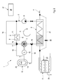
- Fig. 1 und 2
- jeweils eine stark vereinfachte, schaltplanartige Prinzipdarstellung einer Brennkraftmaschine mit einer Abwärmenutzungsvorrichtung bei verschiedenen Ausführungsformen,
- Fig. 3
- eine stark vereinfachte schaltplanartige Prinzipdarstellung eines Verdampfers der Abwärmenutzungsvorrichtung bei einer speziellen Ausführungsform.
- Entsprechend den
Figuren 1 und2 umfasst eine Abwärmenutzungsvorrichtung 1 einen Abwärmenutzungskreis 2, der mit einer Brennkraftmaschine 3 wärmeübertragend gekoppelt ist. Die Brennkraftmaschine 3 umfasst hierzu einen Abgasstrang 4. - Im Abwärmenutzungskreis 2 zirkuliert ein Arbeitsmedium entsprechend einem Drehrichtungspfeil 5, sofern die Abwärmenutzungsvorrichtung 1 ordnungsgemäß in Betrieb ist. Bezüglich der Strömungsrichtung des Arbeitsmediums enthält der Abwärmenutzungskreis 2 hintereinander einen Verdampfer 6, eine Expansionsmaschine 7, einen Kondensator 8 und eine Fördereinrichtung 9. Der Verdampfer 6 dient zum Verdampfen des Arbeitsmediums. Die Expansionsmaschine 7 dient zum Entspannen des Arbeitsmediums, wobei die Expansionsmaschine 7 hier beispielsweise einen Generator 10 antreibt. Der Kondensator 8 dient zum Kondensieren des Arbeitsmediums, wozu der Kondensator 8 beispielsweise an einen Kühlkreis 11 angeschlossen ist. Die Fördereinrichtung 9 dient zum Antreiben des Arbeitsmediums im Abwärmenutzungskreis 2.
- Der Verdampfer 6 ist als Wärmeübertrager ausgestaltet und in den Abgasstrang 4 eingebunden, so dass der Verdampfer 6 mit Abgas der Brennkraftmaschine 3 beaufschlagbar ist.
- Die Abwärmenutzungsvorrichtung 1 ist außerdem mit einem Wärmespeicher 12 ausgestattet, der in den Abwärmenutzungskreis 2 eingebunden ist, derart, dass er vom Arbeitsmedium beaufschlagbar ist. Mit anderen Worten, ein Wärmespeichermaterial 13 des Wärmespeichers 12 ist mit dem Arbeitsmedium wärmeübertragend gekoppelt, so dass Wärme zwischen dem Arbeitsmedium und dem Wärmespeichermedium 13 austauschbar ist.
- Bei den Ausführungsformen der
Figuren 1 und2 ist der Wärmespeicher 12 über einen Vorlauf 14 und einen Rücklauf 15 an den Abwärmenutzungskreis 2 angeschlossen. Im Beispiel sind eine Vorlaufventileinrichtung 16 und eine Rücklaufventileinrichtung 17 vorgesehen, über welche jeweils die Durchströmung des Wärmespeichers 12 mit Arbeitsmedium steuerbar ist. Dabei steuert die Vorlaufventileinrichtung 16 den Vorlauf 14, während die Rücklaufventileinrichtung 17 den Rücklauf 15 steuert. Zweckmäßig ist der Vorlauf 14 zwischen dem Verdampfer 6 und der Expansionsmaschine 7 an den Abwärmenutzungskreis 2 angeschlossen, so dass überhitztes, dampfförmiges Arbeitsmedium zum Aufladen des Wärmespeichers 12 genutzt werden kann. Der Rücklauf 15 ist zweckmäßig zwischen der Expansionsmaschine 7 und dem Kondensator 8 an den Abwärmenutzungskreis 2 angeschlossen. Somit verbleibt der Wärmespeicher 12 auf einer Dampfseite des Abwärmenutzungskreises 2, die sich in der Strömungsrichtung des Arbeitsmediums vom Verdampfer 6 bis zum Kondensator 8 erstreckt. Im Unterschied dazu erstreckt sich eine Flüssigseite des Abwärmenutzungskreises 2 in der Strömungsrichtung des Arbeitsmediums vom Kondensator 8 bis zum Verdampfer 6. - Bei der in
Figur 2 gezeigten Ausführungsform ist ein Kondensatorbypass 18 vorgesehen, der den Kondensator 8 innerhalb des Abwärmenutzungskreises 2 umgeht. Der Kondensatorbypass 18 ist hierzu zwischen der Expansionsmaschine 7 und dem Kondensator 8 einerseits und zwischen dem Kondensator 8 und der Fördereinrichtung 9 andererseits an den Abwärmenutzungskreis 2 angeschlossen. Zur Steuerung des Kondensatorbypasses 18 kann ein Bypassventil 19 vorgesehen sein, das hier in die Rücklaufventileinrichtung 17 integriert ist. - Der zur Kühlung des Kondensators 9 vorgesehene Kühlkreis 11 kann entsprechend einer vorteilhaften Ausführungsform mit der Brennkraftmaschine 3 wärmeübertragend gekoppelt sein. Insbesondere handelt es sich beim Kühlkreis 11 somit um einen Bestandteil eines hier nur teilweise dargestellten Motorkühlkreises 20.
- Ferner ist bei den hier gezeigten Ausführungsformen der
Figuren 1 und2 ein Verdampferbypass 21 vorgesehen, der den Verdampfer 6 abgasseitig umgeht. Zum Steuern dieses Verdampferbypasses 21 kann ein entsprechendes Bypassventil 22 vorgesehen sein. - Die in
Figur 1 gezeigte Ausführungsform der Abwärmenutzungsvorrichtung 1 ist außerdem mit einem Druckspeicher 23 ausgestattet, der an die Flüssigseite des Abwärmenutzungskreises 3 angeschlossen ist. Im Beispiel ist der Druckspeicher 23 zwischen Kondensator 8 und Fördereinrichtung 9 an den Abwärmenutzungskreis 2 angeschlossen. Insbesondere kann ein derartiger Druckspeicher 23 auch in den Wärmespeicher 12 integriert sein, was inFigur 2 angedeutet ist. In diesem Fall befindet sich der Wärmespeicher 23 auf der Dampfseite des Abwärmenutzungskreises 2. - Der Wärmespeicher 12 ist zweckmäßig als Latentwärmespeicher ausgestaltet. Das Wärmespeichermaterial 13 ist dann zweckmäßig ein Phasenwechselmaterial. In
Figur 1 ist eine Druckeinstelleinrichtung 24 angedeutet, mit deren Hilfe der Druck im Phasenwechselmaterial, also im Wärmespeichermaterial 13 eingestellt werden kann. Durch Verändern des Drucks im Phasenwechselmaterial kann die Phasenwechseltemperatur variiert werden. Hierdurch lässt sich der Wärmespeicher 12 besonders einfach an die aktuelle Wärmesituation der Abwärmenutzungsvorrichtung 1 bzw. der Brennkraftmaschine 3 anpassen. - Ebenfalls in
Figur 1 angedeutet ist eine (andere) Druckeinstelleinrichtung 25, mit deren Hilfe der Druck im Arbeitsmedium des Abwärmenutzungskreises 2 eingestellt werden kann. Während eines normalen Betriebs des Abwärmenutzungskreises 2 kann der Druck im Arbeitsmedium einerseits über die Fördereinrichtung 9 und andererseits über die Expansionsmaschine 7 eingestellt werden. In Sonderbetriebszuständen, wie sie beispielsweise während einer Aufwärmphase der Brennkraftmaschine 3 vorliegen, kann es zweckmäßig sein, den Druck im Arbeitsmedium zu verändern, beispielsweise um den Anteil der Dampfseite im Abwärmenutzungskreis 2 zu reduzieren. Insbesondere kann es zweckmäßig sein, die Dampfseite im Abwärmenutzungskreis 2 vorübergehend vollständig zu entfernen, um nur noch flüssiges Arbeitsmedium zu fördern, was die Wärmeübertragung zwischen Wärmespeicher 12 und Abgas erheblich verbessert. - Zum Betreiben der Abwärmenutzungsvorrichtung 1 bzw. zum Betätigen der verstellbaren und einstellbaren Komponenten der Abwärmenutzungseinrichtung 1 bzw. der Brennkraftmaschine 3 kann ferner eine Steuerung 26 vorgesehen sein. Diese Steuerung 26 kann hardwaremäßig in ein Steuergerät 27 der Brennkraftmaschine 3 integriert und/oder softwaremäßig in das Steuergerät 27 implementiert sein.
- Gemäß
Figur 3 kann der Verdampfer 6 gemäß einer speziellen Ausführungsform ein Gehäuse 28 aufweisen, in dem ein Wärmeübertragungsblock 29 angeordnet ist. Der Wärmeübertragungsblock 29 weist einen durch Pfeile angedeuteten Abgaspfad 30, einen Arbeitsmediumpfad 31, einen durch eine geschweifte Klammer angedeuteten Verdampferabschnitt 32 und einen ebenfalls durch eine geschweifte Klammer angedeuteten Wärmespeicherabschnitt 33 auf. Im Verdampferabschnitt 32 sind der Abgaspfad 30 und der Arbeitsmediumpfad 31 wärmeübertragend miteinander gekoppelt. Im Wärmespeicherabschnitt 33 sind der Abgaspfad 30 und der Arbeitsmediumpfad 31 mit dem Wärmespeichermaterial 13 wärmeübertragend gekoppelt, dass innerhalb des Wärmespeicherabschnitts 33 in einer Wärmespeicherstruktur 34 untergebracht ist. Zweckmäßig können Abgaspfad 30 und Arbeitsmediumpfad 31 auch innerhalb des Wärmespeicherabschnitts 33 wärmeübertragend miteinander gekoppelt sein. - Bei der in
Figur 3 gezeigten Ausführungsform sind Verdampferabschnitt 32 und Wärmespeicherabschnitt 33 bezüglich einer Längsrichtung des Wärmeübertragungsblocks 29 axial zueinander benachbart. Ebenso ist eine integrierte Bauform denkbar. - Im Beispiel der
Figur 3 ist in den Verdampfer 6 außerdem der zuvor genannte Verdampferbypass 21 integriert, derart, dass der Verdampferbypass 21 innerhalb des Gehäuses 28 verläuft. Der Verdampferbypass 21 ist dabei über einen ersten Anschluss 35 stromauf des Wärmeübertragungsblocks 29 an den Abgaspfad 30 angeschlossen und stromab des Wärmeübertragungsblocks 29 über einen zweiten Anschluss 36 an den Abgaspfad 30 angeschlossen. Das Bypassventil 22 zum Steuern des Verdampferbypasses 21 ist inFigur 3 nicht dargestellt, kann jedoch beispielsweise in einen der Anschlüsse 35, 36 integriert sein. - Die Steuerung 26 kann zweckmäßig so ausgestaltet bzw. programmiert sein, dass sie das nachfolgend beschriebene Verfahren zum Betreiben der Brennkraftmaschine 3 bzw. der Abwärmenutzungsvorrichtung 1 durchführen kann.
- Während eines Normalbetriebs der Brennkraftmaschine 3 ist auch ein Normalbetrieb der Abwärmenutzungsvorrichtung 1 angestrebt, bei welcher im Abgas mitgeführte Abwärme im Verdampfer 6 zum Verdampfen des Arbeitsmediums verwendet wird, wobei das verdampfte Arbeitsmedium in der Expansionsmaschine 7 zum Antreiben des Generators 10 genutzt wird. Über den Kondensator 8 erfolgt dann die Kondensierung des entspannten und teilweise abgekühlten Arbeitsmediums. Die Fördereinrichtung 9 treibt das Arbeitsmedium wieder durch den Verdampfer 6. Während dieses Normalbetriebs steht somit auch Wärme zum Aufladen des Wärmespeichers 12 zur Verfügung. Dies erfolgt zweckmäßig dadurch, dass ein Teilstrom des Arbeitsmediums durch den Wärmespeicher 12 geführt wird.
- Falls nun eine Temperaturerhöhung des Abgases vorgenommen werden soll, z.B. um eine stromab des Verdampfers 6 im Abgasstrang 4 angeordnete Komponente der Abgasanlage auf eine vorbestimmte Betriebstemperatur zu bringen, kann dem Wärmespeicher 12 Wärme entnommen und diese über den Verdampfer 6 dem Abgas zugeführt werden. Hierzu kann beispielsweise gemäß
Figur 2 der Kondensator 8 vorübergehend über den Kondensatorbypass 18 umgangen werden, um heißes Arbeitsmedium dem Verdampfer 6 zuzuführen. - Falls jedoch entsprechend der in
Figur 1 gezeigten Ausführungsform kein derartiger Kondensatorbypass 18 vorgesehen ist, kann beispielsweise der Kühlkreis 11 vorübergehend deaktiviert werden. Ebenso ist es möglich, vorübergehend die Förderrichtung der Fördereinrichtung 9 umzukehren, um so auf möglichst kurzem Weg heißes Arbeitsmedium vom Wärmespeicher 12 zum Verdampfer 6 zu fördern. - Eine derartige Temperaturerhöhung des Abgases ist insbesondere dann erwünscht, wenn die Brennkraftmaschine 3 kaltgestartet wird und dementsprechend zunächst eine Kaltstartphase durchläuft. Ein Kaltstart liegt dann vor, wenn die Brennkraftmaschine 3 im Wesentlichen Umgebungstemperatur besitzt.
- Während dieser Kaltstartphase kann wie zuvor beschrieben Wärme aus dem Wärmespeicher 12 über das Arbeitsmedium zum Verdampfer 6 gefördert werden und über den Verdampfer 6 dem Abgas zugeführt werden, um die Abgasbehandlungskomponenten rascher auf Betriebstemperatur zu bringen.
- Zusätzlich ist es während dieser Kaltstartphase außerdem möglich, über den Kühlkreis 11 Wärme der Brennkraftmaschine 3 zuzuführen, sofern es sich beim Kühlkreis 11 um einen Bestandteil des Motorkühlkreises 20 handelt. Falls ein Kondensatorbypass 18 vorgesehen ist, ist er für diesen Fall deaktiviert.
Claims (14)
- Abgaswärmenutzungsvorrichtung für eine Brennkraftmaschine (3), insbesondere eines Fahrzeugs,- mit einem Abwärmenutzungskreis (2), in dem ein Arbeitsmedium zirkuliert,- mit einem im Abwärmenutzungskreis (2) angeordneten Verdampfer (6) zum Verdampfen des Arbeitsmediums, der mit Abgas der Brennkraftmaschine (3) beaufschlagbar ist,- mit einer im Abwärmenutzungskreis (2) stromab des Verdampfers (6) angeordneten Expansionsmaschine (7) zum Entspannen des Arbeitsmediums,- mit einem im Abwärmenutzungskreis (2) stromab der Expansionsmaschine (7) angeordneten Kondensator (8) zum Kondensieren des Arbeitsmediums,- mit einer im Abwärmenutzungskreis (2) stromab des Kondensators (8) angeordneten Fördereinrichtung (9) zum Antreiben des Arbeitsmediums im Abwärmenutzungskreis (2),- mit einem Wärmespeicher (12),
dadurch gekennzeichnet,
dass der Wärmespeicher (12) in den Abwärmenutzungskreis (2) eingebunden und vom Arbeitsmedium beaufschlagbar ist. - Abwärmenutzungsvorrichtung nach Anspruch 1,
dadurch gekennzeichnet,
dass der Wärmespeicher (12) über einen Vorlauf (14) und einen Rücklauf (15) an den Abwärmenutzungskreis (2) angeschlossen ist, wobei insbesondere vorgesehen sein kann, dass eine Vorlaufventileinrichtung (16) zum Steuern des Vorlaufs (14) und/oder eine Rücklaufventileinrichtung (17) zum Steuern des Rücklaufs (15) vorgesehen ist/sind. - Wärmenutzungsvorrichtung nach Anspruch 2,
dadurch gekennzeichnet,
dass der Vorlauf (14) zwischen Verdampfer (6) und Expansionsmaschine (7) an den Abwärmenutzungskreis (2) angeschlossen ist, wobei der Rücklauf (15) zwischen der Expansionsmaschine (7) und Kondensator (8) an den Abwärmenutzungskreis (2) angeschlossen ist. - Abwärmenutzungsvorrichtung nach einem der Ansprüche 1 bis 3,
dadurch gekennzeichnet,
dass ein Kondensatorbypass (18) zur Umgehung des Kondensators (8) vorgesehen ist, der einerseits zwischen der Expansionsmaschine (7) und Kondensator (8) und andererseits zwischen Kondensator (8) und Fördereinrichtung (9) an den Abwärmenutzungskreis (2) angeschlossen ist, wobei insbesondere vorgesehen sein kann, dass ein Bypassventil (19) zum Steuern des Kondensatorbypasses (18) vorgesehen ist. - Abwärmenutzungsvorrichtung nach einem der Ansprüche 1 bis 4,
dadurch gekennzeichnet,
dass der Kondensator (8) mit einem Kühlkreis (11) wärmeübertragend gekoppelt ist, der außerdem mit einer Brennkraftmaschine (3) wärmeübertragend gekoppelt ist, die das Abgas zum Beaufschlagen des Verdampfers (6) erzeugt. - Wärmenutzungsvorrichtung nach einem der Ansprüche 1 bis 5,
dadurch gekennzeichnet,
dass ein Verdampferbypass (21) zur abgasseitigen Umgehung des Verdampfers (6) vorgesehen ist, wobei insbesondere ein Bypassventil (22) zum Steuern des Verdampferbypasses (21) vorgesehen sein kann. - Abwärmenutzungsvorrichtung nach einem der Ansprüche 1 bis 6,
dadurch gekennzeichnet,- dass der Wärmespeicher (12) als Latentwärmespeicher ausgestaltet ist, der mit einem Phasenwechselmaterial arbeitet, und/oder- dass eine Druckeinstelleinrichtung (24) zum Einstellen des Drucks im Phasenwechselmaterial vorgesehen ist, und/oder- dass eine Druckeinstelleinrichtung (25) zum Einstellen des Drucks im Arbeitsmedium vorgesehen ist. - Abwärmenutzungsvorrichtung nach einem der Ansprüche 1 und 4-7,
dadurch gekennzeichnet,
dass der Wärmespeicher (12) in den Verdampfer (6) integriert ist. - Abwärmenutzungsvorrichtung nach den Ansprüchen 6 und 8,
dadurch gekennzeichnet,
dass der Verdampferbypass (21) in den Verdampfer (6) integriert ist. - Wärmenutzungsvorrichtung nach Anspruch 8 oder 9,
dadurch gekennzeichnet,
dass der Verdampfer (6) einen Wärmeübertragungsblock (29) aufweist, der einen Abgaspfad (30), einen Arbeitsmediumpfad (31), einen Verdampferabschnitt (32) und einen Wärmespeicherabschnitt (33) aufweist, wobei im Verdampferabschnitt (32) der Abgaspfad (30) und der Arbeitsmediumpfad (31) wärmeübertragend gekoppelt sind, während im Wärmespeicherabschnitt (33) der Abgaspfad (30) und der Arbeitsmediumpfad (31) mit dem Wärmespeichermaterial (13) des Wärmespeichers (12) wärmeübertragend gekoppelt sind. - Verfahren zum Betreiben einer Brennkraftmaschine (3), insbesondere eines Kraftfahrzeugs, die mit einer Abwärmenutzungsvorrichtung (1) nach einem der Ansprüche 1 bis 10 ausgestattet ist, bei dem zum Aufladen des Wärmespeichers (12) zumindest ein Teilstrom des Arbeitsmediums durch den Wärmespeicher (12) geführt wird.
- Verfahren nach Anspruch 11, bei dem während einer Kaltstartphase der Brennkraftmaschine (3) dem Wärmespeicher (12) Wärme entnommen und über den Kondensator (8) und über den Kühlkreis (11) der Brennkraftmaschine (3) zugeführt wird.
- Verfahren nach Anspruch 11 oder 12, bei dem zur Temperaturerhöhung des Abgases dem Wärmespeicher (12) Wärme entnommen und über den Verdampfer (6) dem Abgas zugeführt wird.
- Verfahren nach einem der Ansprüche 11 bis 13, wobei der Wärmespeicher (12) unter Umgehung der Expansionsmaschine (7) einerseits zwischen Verdampfer (6) und Expansionsmaschine (7) und andererseits zwischen Expansionsmaschine (7) und Kondensator (8) an den Abwärmenutzungskreis (2) angeschlossen ist, bei dem zur Temperaturerhöhung des Abgases dem Wärmespeicher (12) Wärme entnommen und über den Verdampfer (6) dem Abgas zugeführt wird, wobei hierzu die Förderrichtung der Fördereinrichtung (9) umgekehrt wird.
Applications Claiming Priority (1)
| Application Number | Priority Date | Filing Date | Title |
|---|---|---|---|
| DE102011076054A DE102011076054B4 (de) | 2011-05-18 | 2011-05-18 | Abwärmenutzungsvorrichtung |
Publications (3)
| Publication Number | Publication Date |
|---|---|
| EP2525052A2 true EP2525052A2 (de) | 2012-11-21 |
| EP2525052A3 EP2525052A3 (de) | 2014-06-18 |
| EP2525052B1 EP2525052B1 (de) | 2017-05-03 |
Family
ID=46148636
Family Applications (1)
| Application Number | Title | Priority Date | Filing Date |
|---|---|---|---|
| EP12167881.7A Not-in-force EP2525052B1 (de) | 2011-05-18 | 2012-05-14 | Abwärmenutzungsvorrichtung |
Country Status (5)
| Country | Link |
|---|---|
| US (1) | US9494055B2 (de) |
| EP (1) | EP2525052B1 (de) |
| JP (1) | JP5480933B2 (de) |
| CN (1) | CN102787944B (de) |
| DE (1) | DE102011076054B4 (de) |
Cited By (5)
| Publication number | Priority date | Publication date | Assignee | Title |
|---|---|---|---|---|
| EP2824300A1 (de) * | 2013-07-09 | 2015-01-14 | Volkswagen Aktiengesellschaft | Antriebseinheit für ein Kraftfahrzeug |
| EP2832340A1 (de) * | 2013-08-02 | 2015-02-04 | Astrium GmbH | Isolierbehältervorrichtung |
| WO2015043949A1 (de) * | 2013-09-24 | 2015-04-02 | Siemens Aktiengesellschaft | Verfahren zum betreiben einer dampfturbinenanlage |
| WO2015067434A1 (de) * | 2013-11-06 | 2015-05-14 | Robert Bosch Gmbh | Verfahren zum betreiben eines systems zur energierückgewinnung aus einem abwärmestrom einer brennkraftmaschine |
| WO2018050407A1 (de) * | 2016-09-13 | 2018-03-22 | Robert Bosch Gmbh | Vorrichtung zur rückgewinnung von wärme aus dem abgasstrom einer brennkraftmaschine |
Families Citing this family (46)
| Publication number | Priority date | Publication date | Assignee | Title |
|---|---|---|---|---|
| US20210063836A1 (en) | 2017-04-26 | 2021-03-04 | View, Inc. | Building network |
| US10303035B2 (en) | 2009-12-22 | 2019-05-28 | View, Inc. | Self-contained EC IGU |
| DE102010042401A1 (de) * | 2010-10-13 | 2012-04-19 | Robert Bosch Gmbh | Vorrichtung und Verfahren zur Abwärmenutzung einer Brennkraftmaschine |
| DE102012000100A1 (de) * | 2011-01-06 | 2012-07-12 | Cummins Intellectual Property, Inc. | Rankine-kreisprozess-abwärmenutzungssystem |
| US10989977B2 (en) | 2011-03-16 | 2021-04-27 | View, Inc. | Onboard controller for multistate windows |
| US11054792B2 (en) | 2012-04-13 | 2021-07-06 | View, Inc. | Monitoring sites containing switchable optical devices and controllers |
| DE102011105709A1 (de) * | 2011-06-22 | 2012-12-27 | Man Truck & Bus Ag | Verfahren und Vorrichtung zur Rückgewinnung von Wärme und deren Umwandlung in mechanische Leistung in einem Antriebssystem für Kraftfahrzeuge |
| EP3223532B1 (de) | 2012-04-13 | 2019-10-09 | View, Inc. | Anwendungen zur steuerung optisch schaltbarer vorrichtungen |
| DE102012222082B4 (de) * | 2012-12-03 | 2017-05-18 | Robert Bosch Gmbh | Vorrichtung und Verfahren zur Abwärmenutzung einer Brennkraftmaschine |
| JP6064575B2 (ja) * | 2012-12-17 | 2017-01-25 | いすゞ自動車株式会社 | 内燃機関の排熱回収装置と内燃機関の排熱回収方法 |
| CN103967543B (zh) * | 2013-01-24 | 2017-08-11 | 基准涡轮动力(广州)有限公司 | 一种储能蒸汽循环系统 |
| KR101434908B1 (ko) | 2013-05-23 | 2014-08-29 | 포스코에너지 주식회사 | 중저온 폐열을 활용한 난방 열원 또는 전기 생산 시스템, 및 그 제어방법 |
| DE102013211410B4 (de) * | 2013-06-18 | 2017-05-18 | Robert Bosch Gmbh | Abwärmerückgewinnungssystem |
| DE102013011519A1 (de) | 2013-07-09 | 2015-01-15 | Volkswagen Ag | Wärmetauschvorrichtung und Antriebseinheit für ein Kraftfahrzeug |
| DE102013011478B4 (de) | 2013-07-09 | 2022-09-15 | Volkswagen Aktiengesellschaft | Antriebseinheit für ein Kraftfahrzeug |
| DE102013011477A1 (de) | 2013-07-09 | 2015-01-15 | Volkswagen Aktiengesellschaft | Antriebseinheit für ein Kraftfahrzeug |
| DE102013107251B4 (de) * | 2013-07-09 | 2019-12-24 | Deutsches Zentrum für Luft- und Raumfahrt e.V. | Dampfkraftvorrichtung und Verfahren zum Betreiben einer Dampfkraftvorrichtung |
| DE102013011520A1 (de) | 2013-07-09 | 2015-01-15 | Volkswagen Aktiengesellschaft | Antriebseinheit für ein Kraftfahrzeug |
| US9169751B2 (en) * | 2013-10-02 | 2015-10-27 | Ford Global Technologies, Llc | Methods and systems for utilizing waste heat for a hybrid vehicle |
| WO2015058370A1 (en) * | 2013-10-23 | 2015-04-30 | General Electric Company | Combined cycle power plant with heat storage device |
| US9783025B2 (en) * | 2013-11-13 | 2017-10-10 | Mahle International Gmbh | Method for cooling and/or heating media, preferably in a motor vehicle, and a sorptive heat and cold storage system |
| US11868103B2 (en) | 2014-03-05 | 2024-01-09 | View, Inc. | Site monitoring system |
| KR102336168B1 (ko) | 2014-03-05 | 2021-12-07 | 뷰, 인크. | 스위칭가능한 광 디바이스들 및 제어기들을 포함하는 사이트들 모니터링 |
| US10481459B2 (en) | 2014-06-30 | 2019-11-19 | View, Inc. | Control methods and systems for networks of optically switchable windows during reduced power availability |
| JP6295913B2 (ja) * | 2014-10-08 | 2018-03-20 | 株式会社デンソー | 蓄熱システム |
| CA2970300A1 (en) | 2014-12-08 | 2016-06-16 | View, Inc. | Multiple interacting systems at a site |
| US11740948B2 (en) | 2014-12-08 | 2023-08-29 | View, Inc. | Multiple interacting systems at a site |
| DE102014018955A1 (de) * | 2014-12-18 | 2016-06-23 | Daimler Ag | Kraftfahrzeug und Verfahren zu dessen Betrieb |
| US9784141B2 (en) * | 2015-01-14 | 2017-10-10 | Ford Global Technologies, Llc | Method and system of controlling a thermodynamic system in a vehicle |
| DE102015214728A1 (de) * | 2015-08-03 | 2017-02-09 | Robert Bosch Gmbh | Abwärmenutzungsanordnung einer Brennkraftmaschine und Verfahren zum Betrieb der Abwärmenutzungsanordnung |
| US11384596B2 (en) | 2015-09-18 | 2022-07-12 | View, Inc. | Trunk line window controllers |
| US12366111B2 (en) | 2015-09-18 | 2025-07-22 | View Operating Corporation | Trunk line window controllers |
| DE102016206801A1 (de) * | 2016-04-21 | 2017-10-26 | Mtu Friedrichshafen Gmbh | System zur Durchführung eines thermodynamischen Kreisprozesses, Anordnung mit einem solchen System sowie Kraftfahrzeug mit einer solchen Anordnung |
| CN105781788B (zh) * | 2016-04-29 | 2017-04-12 | 吉林大学 | 车用内燃机余热复合利用系统 |
| CN105986865B (zh) * | 2016-06-02 | 2019-01-18 | 浙江工商大学 | 一种基于船舶主机尾气热能的发电系统 |
| JP6741619B2 (ja) * | 2017-03-30 | 2020-08-19 | 日野自動車株式会社 | 廃熱回収装置 |
| TW201907213A (zh) | 2017-04-26 | 2019-02-16 | 美商唯景公司 | 可著色窗系統計算平台 |
| US12603091B2 (en) | 2017-04-26 | 2026-04-14 | View Operating Corporation | Immersive collaboration of remote participants via media displays |
| US12147142B2 (en) | 2017-04-26 | 2024-11-19 | View, Inc. | Remote management of a facility |
| US11092041B2 (en) | 2017-09-22 | 2021-08-17 | Tenneco Gmbh | Condenser assembly and control method for use with Rankine power system |
| CN109973242B (zh) * | 2019-04-23 | 2024-08-06 | 沪东重机有限公司 | 一种基于相变蓄热的发动机余热利用装置及使用方法 |
| JP7644501B2 (ja) | 2019-05-09 | 2025-03-12 | ビュー オペレーティング コーポレーション | 建物内の制御されたカバレッジのためのアンテナシステム |
| US11631493B2 (en) | 2020-05-27 | 2023-04-18 | View Operating Corporation | Systems and methods for managing building wellness |
| CN111002837A (zh) * | 2019-12-25 | 2020-04-14 | 金跃祖 | 一种变速器能量回收系统 |
| CN111441837B (zh) * | 2020-03-19 | 2022-05-10 | 天津大学 | 一种内燃机余热回收装置及其回收方法 |
| TW202206925A (zh) | 2020-03-26 | 2022-02-16 | 美商視野公司 | 多用戶端網路中之存取及傳訊 |
Citations (1)
| Publication number | Priority date | Publication date | Assignee | Title |
|---|---|---|---|---|
| DE102007033611A1 (de) | 2007-07-17 | 2009-01-22 | Amovis Gmbh | Anordnung zur Abgaswärmenutzung |
Family Cites Families (23)
| Publication number | Priority date | Publication date | Assignee | Title |
|---|---|---|---|---|
| JPS62167811U (de) * | 1986-04-15 | 1987-10-24 | ||
| JPH08319805A (ja) * | 1995-05-24 | 1996-12-03 | Toshiba Corp | 火力発電プラントおよびその運転方法 |
| JP3230799B2 (ja) * | 1996-10-11 | 2001-11-19 | 日野自動車株式会社 | ディーゼル機関の排ガス浄化装置 |
| US20020014329A1 (en) * | 1998-06-29 | 2002-02-07 | Peter Carr | Integrated heating and cooling system for a vehicle |
| CN2395216Y (zh) * | 1999-07-23 | 2000-09-06 | 浙江大学 | 组合相变材料蓄热设备 |
| JP2002115506A (ja) * | 2000-10-11 | 2002-04-19 | Honda Motor Co Ltd | ランキンサイクル装置 |
| JP2005016326A (ja) * | 2003-06-23 | 2005-01-20 | Denso Corp | 発熱体の廃熱利用装置 |
| JP4546788B2 (ja) * | 2004-08-25 | 2010-09-15 | サンデン株式会社 | ランキンシステム |
| JP2007032561A (ja) * | 2005-06-20 | 2007-02-08 | Sango Co Ltd | 排気熱回収装置 |
| DE102006043139B4 (de) * | 2006-09-14 | 2015-02-12 | Man Truck & Bus Ag | Vorrichtung zur Gewinnung von mechanischer oder elektrischer Energie aus der Abwärme eines Verbrennungsmotors eines Kraftfahrzeugs |
| JP4281789B2 (ja) * | 2006-12-06 | 2009-06-17 | トヨタ自動車株式会社 | 排気熱回収装置 |
| JP2009133266A (ja) * | 2007-11-30 | 2009-06-18 | Sanden Corp | 内燃機関の廃熱利用装置 |
| JP2009185773A (ja) * | 2008-02-08 | 2009-08-20 | Sanden Corp | 廃熱利用装置 |
| JP2009191624A (ja) * | 2008-02-12 | 2009-08-27 | Toyota Motor Corp | エンジンの廃熱回収装置 |
| DE202008002781U1 (de) * | 2008-02-27 | 2008-07-24 | Krah, Benjamin | PCM-KFZ-Abgaswärmespeicher zur Anbindung an häusliche Warmwasser- und Heizsysteme |
| JP2010112198A (ja) | 2008-11-04 | 2010-05-20 | Toyota Motor Corp | 内燃機関の排気浄化装置 |
| JP4957707B2 (ja) * | 2008-11-14 | 2012-06-20 | 株式会社デンソー | 蓄熱装置 |
| DE102009035522B4 (de) * | 2009-07-31 | 2013-09-19 | Iav Gmbh Ingenieurgesellschaft Auto Und Verkehr | Verfahren und Vorrichtung zur verbesserten Energieausnutzung der Wärmeenergie von Brennkraftmaschinen |
| RU2012116504A (ru) * | 2009-09-25 | 2013-10-27 | ДАУ ГЛОБАЛ ТЕКНОЛОДЖИЗ ЭлЭлСи | Система теплопередачи, использующая материалы, аккумулирующие тепловую энергию |
| US8161949B2 (en) * | 2009-10-15 | 2012-04-24 | International Engine Intellectual Property Company, Llc | Exhaust gas recirculation cooler system |
| US20110185726A1 (en) * | 2010-02-04 | 2011-08-04 | Cleanpower Technology, Inc. | Energy separation and recovery system for mobile application |
| JP5397314B2 (ja) * | 2010-05-14 | 2014-01-22 | トヨタ自動車株式会社 | 車両の熱管理システム |
| DE102011105709A1 (de) * | 2011-06-22 | 2012-12-27 | Man Truck & Bus Ag | Verfahren und Vorrichtung zur Rückgewinnung von Wärme und deren Umwandlung in mechanische Leistung in einem Antriebssystem für Kraftfahrzeuge |
-
2011
- 2011-05-18 DE DE102011076054A patent/DE102011076054B4/de not_active Expired - Fee Related
-
2012
- 2012-05-14 EP EP12167881.7A patent/EP2525052B1/de not_active Not-in-force
- 2012-05-17 US US13/474,173 patent/US9494055B2/en not_active Expired - Fee Related
- 2012-05-17 JP JP2012113243A patent/JP5480933B2/ja active Active
- 2012-05-18 CN CN201210154997.7A patent/CN102787944B/zh not_active Expired - Fee Related
Patent Citations (1)
| Publication number | Priority date | Publication date | Assignee | Title |
|---|---|---|---|---|
| DE102007033611A1 (de) | 2007-07-17 | 2009-01-22 | Amovis Gmbh | Anordnung zur Abgaswärmenutzung |
Cited By (6)
| Publication number | Priority date | Publication date | Assignee | Title |
|---|---|---|---|---|
| EP2824300A1 (de) * | 2013-07-09 | 2015-01-14 | Volkswagen Aktiengesellschaft | Antriebseinheit für ein Kraftfahrzeug |
| EP2832340A1 (de) * | 2013-08-02 | 2015-02-04 | Astrium GmbH | Isolierbehältervorrichtung |
| WO2015043949A1 (de) * | 2013-09-24 | 2015-04-02 | Siemens Aktiengesellschaft | Verfahren zum betreiben einer dampfturbinenanlage |
| US9982569B2 (en) | 2013-09-24 | 2018-05-29 | Siemens Aktiengesellschaft | Method for operating a steam turbine plant |
| WO2015067434A1 (de) * | 2013-11-06 | 2015-05-14 | Robert Bosch Gmbh | Verfahren zum betreiben eines systems zur energierückgewinnung aus einem abwärmestrom einer brennkraftmaschine |
| WO2018050407A1 (de) * | 2016-09-13 | 2018-03-22 | Robert Bosch Gmbh | Vorrichtung zur rückgewinnung von wärme aus dem abgasstrom einer brennkraftmaschine |
Also Published As
| Publication number | Publication date |
|---|---|
| JP5480933B2 (ja) | 2014-04-23 |
| EP2525052A3 (de) | 2014-06-18 |
| JP2012241718A (ja) | 2012-12-10 |
| US9494055B2 (en) | 2016-11-15 |
| DE102011076054A1 (de) | 2012-11-22 |
| CN102787944B (zh) | 2015-07-01 |
| DE102011076054B4 (de) | 2013-12-05 |
| EP2525052B1 (de) | 2017-05-03 |
| US20120291418A1 (en) | 2012-11-22 |
| CN102787944A (zh) | 2012-11-21 |
Similar Documents
| Publication | Publication Date | Title |
|---|---|---|
| EP2525052B1 (de) | Abwärmenutzungsvorrichtung | |
| EP3454401B1 (de) | Kraftfahrzeug mit einem kühlsystem | |
| EP3146160B1 (de) | Verfahren zur rückgewinnung von wärme aus verbrennungsmotoren sowie zur umwandlung der rückgewonnenen wärme in mechanische energie | |
| EP1925806A2 (de) | System mit einem Organic-Rankine-Kreislauf zum Antrieb zumindest einer Expansionsmaschine, Wärmetauscher zum Antrieb einer Expansionsmaschine, Verfahren zum Betreiben zumindest einer Expansionsmaschine | |
| DE102005012399B4 (de) | Wärmerückgewinnungssystem | |
| EP2863022B1 (de) | Antriebseinheit für ein Kraftfahrzeug | |
| EP2983928B1 (de) | Heizsystem und verfahren zum heizen eines fahrzeuginnenraums eines eine brennkraftmaschine aufweisenden fahrzeugs | |
| EP2846017B1 (de) | Wärmetauschvorrichtung und Antriebseinheit für ein Kraftfahrzeug | |
| DE102017125409A1 (de) | Abwärmerückgewinnung für energieerzeugung und motorwarmlauf | |
| DE102016100296A1 (de) | Verfahren und System zum Steuern eines thermodynamischen Systems in einem Fahrzeug | |
| DE102010033124A1 (de) | Brennkraftmaschine mit einer Wärmerückgewinnungsvorrichtung und Verfahren zum Betrieb einer Brennkraftmaschine | |
| EP2824300B1 (de) | Antriebseinheit für ein Kraftfahrzeug | |
| EP1331113A1 (de) | Einrichtung zum Kühlen und/oder Heizen eines Raumes, mit einem Adsorptionskühlkreis | |
| EP2527635A2 (de) | Energierückgewinnungssystem | |
| EP2345803A1 (de) | Kühlkreislauf einer Brennkraftmaschine sowie ein Arbeitsverfahren zum Betrieb eines Kühlkreislaufs | |
| DE102012222082B4 (de) | Vorrichtung und Verfahren zur Abwärmenutzung einer Brennkraftmaschine | |
| DE102015016783A1 (de) | Vorrichtung zur Gewinnung von Energie aus Abwärme einer Verbrennungskraftmaschine eines Kraftfahrzeugs | |
| DE102013224125A1 (de) | System zur Rückgewinnung von Abgaswärme | |
| WO2017178537A1 (de) | Vorrichtung und verfahren zur energierückgewinnung | |
| WO2014086442A1 (de) | Fahrzeugklimatisierungsanlage | |
| DE102018210147B4 (de) | Wärmemanagement in einem Kraftfahrzeug | |
| DE102018218065A1 (de) | Abwärmenutzungseinrichtung, insbesondere für eine Brennkraftmaschine eines Kraftfahrzeugs | |
| DE102010025185A1 (de) | Abwärmenutzungsvorrichtung | |
| DE102018210146A1 (de) | Wärmemanagement in einem Kraftfahrzeug | |
| WO2016162118A1 (de) | Vorrichtung zur abwärmerückgewinnung und verfahren zu deren betrieb |
Legal Events
| Date | Code | Title | Description |
|---|---|---|---|
| PUAI | Public reference made under article 153(3) epc to a published international application that has entered the european phase |
Free format text: ORIGINAL CODE: 0009012 |
|
| AK | Designated contracting states |
Kind code of ref document: A2 Designated state(s): AL AT BE BG CH CY CZ DE DK EE ES FI FR GB GR HR HU IE IS IT LI LT LU LV MC MK MT NL NO PL PT RO RS SE SI SK SM TR |
|
| AX | Request for extension of the european patent |
Extension state: BA ME |
|
| RAP1 | Party data changed (applicant data changed or rights of an application transferred) |
Owner name: EBERSPAECHER EXHAUST TECHNOLOGY GMBH & CO. KG |
|
| PUAL | Search report despatched |
Free format text: ORIGINAL CODE: 0009013 |
|
| AK | Designated contracting states |
Kind code of ref document: A3 Designated state(s): AL AT BE BG CH CY CZ DE DK EE ES FI FR GB GR HR HU IE IS IT LI LT LU LV MC MK MT NL NO PL PT RO RS SE SI SK SM TR |
|
| AX | Request for extension of the european patent |
Extension state: BA ME |
|
| RIC1 | Information provided on ipc code assigned before grant |
Ipc: F01K 3/10 20060101AFI20140515BHEP Ipc: F01K 23/06 20060101ALI20140515BHEP Ipc: F01K 15/02 20060101ALI20140515BHEP Ipc: F01N 5/02 20060101ALI20140515BHEP Ipc: F02G 5/02 20060101ALI20140515BHEP Ipc: F28D 20/02 20060101ALI20140515BHEP |
|
| 17P | Request for examination filed |
Effective date: 20141215 |
|
| RBV | Designated contracting states (corrected) |
Designated state(s): AL AT BE BG CH CY CZ DE DK EE ES FI FR GB GR HR HU IE IS IT LI LT LU LV MC MK MT NL NO PL PT RO RS SE SI SK SM TR |
|
| REG | Reference to a national code |
Ref country code: DE Ref legal event code: R079 Ref document number: 502012010219 Country of ref document: DE Free format text: PREVIOUS MAIN CLASS: F01K0023060000 Ipc: F01K0003100000 |
|
| GRAP | Despatch of communication of intention to grant a patent |
Free format text: ORIGINAL CODE: EPIDOSNIGR1 |
|
| RIC1 | Information provided on ipc code assigned before grant |
Ipc: F01K 3/10 20060101AFI20161111BHEP Ipc: F28D 20/02 20060101ALI20161111BHEP Ipc: F01K 23/06 20060101ALI20161111BHEP Ipc: F28D 21/00 20060101ALI20161111BHEP Ipc: F28D 20/00 20060101ALI20161111BHEP Ipc: F02G 5/02 20060101ALI20161111BHEP Ipc: F01N 5/02 20060101ALI20161111BHEP Ipc: F01K 15/02 20060101ALI20161111BHEP |
|
| INTG | Intention to grant announced |
Effective date: 20161207 |
|
| GRAS | Grant fee paid |
Free format text: ORIGINAL CODE: EPIDOSNIGR3 |
|
| GRAA | (expected) grant |
Free format text: ORIGINAL CODE: 0009210 |
|
| AK | Designated contracting states |
Kind code of ref document: B1 Designated state(s): AL AT BE BG CH CY CZ DE DK EE ES FI FR GB GR HR HU IE IS IT LI LT LU LV MC MK MT NL NO PL PT RO RS SE SI SK SM TR |
|
| REG | Reference to a national code |
Ref country code: GB Ref legal event code: FG4D Free format text: NOT ENGLISH |
|
| REG | Reference to a national code |
Ref country code: AT Ref legal event code: REF Ref document number: 890238 Country of ref document: AT Kind code of ref document: T Effective date: 20170515 Ref country code: CH Ref legal event code: EP |
|
| REG | Reference to a national code |
Ref country code: IE Ref legal event code: FG4D Free format text: LANGUAGE OF EP DOCUMENT: GERMAN |
|
| REG | Reference to a national code |
Ref country code: DE Ref legal event code: R096 Ref document number: 502012010219 Country of ref document: DE |
|
| REG | Reference to a national code |
Ref country code: FR Ref legal event code: PLFP Year of fee payment: 6 |
|
| REG | Reference to a national code |
Ref country code: SE Ref legal event code: TRGR |
|
| REG | Reference to a national code |
Ref country code: NL Ref legal event code: MP Effective date: 20170503 |
|
| REG | Reference to a national code |
Ref country code: LT Ref legal event code: MG4D |
|
| PG25 | Lapsed in a contracting state [announced via postgrant information from national office to epo] |
Ref country code: LT Free format text: LAPSE BECAUSE OF FAILURE TO SUBMIT A TRANSLATION OF THE DESCRIPTION OR TO PAY THE FEE WITHIN THE PRESCRIBED TIME-LIMIT Effective date: 20170503 Ref country code: GR Free format text: LAPSE BECAUSE OF FAILURE TO SUBMIT A TRANSLATION OF THE DESCRIPTION OR TO PAY THE FEE WITHIN THE PRESCRIBED TIME-LIMIT Effective date: 20170804 Ref country code: FI Free format text: LAPSE BECAUSE OF FAILURE TO SUBMIT A TRANSLATION OF THE DESCRIPTION OR TO PAY THE FEE WITHIN THE PRESCRIBED TIME-LIMIT Effective date: 20170503 Ref country code: HR Free format text: LAPSE BECAUSE OF FAILURE TO SUBMIT A TRANSLATION OF THE DESCRIPTION OR TO PAY THE FEE WITHIN THE PRESCRIBED TIME-LIMIT Effective date: 20170503 Ref country code: NO Free format text: LAPSE BECAUSE OF FAILURE TO SUBMIT A TRANSLATION OF THE DESCRIPTION OR TO PAY THE FEE WITHIN THE PRESCRIBED TIME-LIMIT Effective date: 20170803 Ref country code: ES Free format text: LAPSE BECAUSE OF FAILURE TO SUBMIT A TRANSLATION OF THE DESCRIPTION OR TO PAY THE FEE WITHIN THE PRESCRIBED TIME-LIMIT Effective date: 20170503 |
|
| PG25 | Lapsed in a contracting state [announced via postgrant information from national office to epo] |
Ref country code: NL Free format text: LAPSE BECAUSE OF FAILURE TO SUBMIT A TRANSLATION OF THE DESCRIPTION OR TO PAY THE FEE WITHIN THE PRESCRIBED TIME-LIMIT Effective date: 20170503 Ref country code: PL Free format text: LAPSE BECAUSE OF FAILURE TO SUBMIT A TRANSLATION OF THE DESCRIPTION OR TO PAY THE FEE WITHIN THE PRESCRIBED TIME-LIMIT Effective date: 20170503 Ref country code: IS Free format text: LAPSE BECAUSE OF FAILURE TO SUBMIT A TRANSLATION OF THE DESCRIPTION OR TO PAY THE FEE WITHIN THE PRESCRIBED TIME-LIMIT Effective date: 20170903 Ref country code: RS Free format text: LAPSE BECAUSE OF FAILURE TO SUBMIT A TRANSLATION OF THE DESCRIPTION OR TO PAY THE FEE WITHIN THE PRESCRIBED TIME-LIMIT Effective date: 20170503 Ref country code: LV Free format text: LAPSE BECAUSE OF FAILURE TO SUBMIT A TRANSLATION OF THE DESCRIPTION OR TO PAY THE FEE WITHIN THE PRESCRIBED TIME-LIMIT Effective date: 20170503 Ref country code: BG Free format text: LAPSE BECAUSE OF FAILURE TO SUBMIT A TRANSLATION OF THE DESCRIPTION OR TO PAY THE FEE WITHIN THE PRESCRIBED TIME-LIMIT Effective date: 20170803 |
|
| REG | Reference to a national code |
Ref country code: CH Ref legal event code: PL |
|
| PG25 | Lapsed in a contracting state [announced via postgrant information from national office to epo] |
Ref country code: EE Free format text: LAPSE BECAUSE OF FAILURE TO SUBMIT A TRANSLATION OF THE DESCRIPTION OR TO PAY THE FEE WITHIN THE PRESCRIBED TIME-LIMIT Effective date: 20170503 Ref country code: RO Free format text: LAPSE BECAUSE OF FAILURE TO SUBMIT A TRANSLATION OF THE DESCRIPTION OR TO PAY THE FEE WITHIN THE PRESCRIBED TIME-LIMIT Effective date: 20170503 Ref country code: DK Free format text: LAPSE BECAUSE OF FAILURE TO SUBMIT A TRANSLATION OF THE DESCRIPTION OR TO PAY THE FEE WITHIN THE PRESCRIBED TIME-LIMIT Effective date: 20170503 Ref country code: SK Free format text: LAPSE BECAUSE OF FAILURE TO SUBMIT A TRANSLATION OF THE DESCRIPTION OR TO PAY THE FEE WITHIN THE PRESCRIBED TIME-LIMIT Effective date: 20170503 Ref country code: CZ Free format text: LAPSE BECAUSE OF FAILURE TO SUBMIT A TRANSLATION OF THE DESCRIPTION OR TO PAY THE FEE WITHIN THE PRESCRIBED TIME-LIMIT Effective date: 20170503 |
|
| REG | Reference to a national code |
Ref country code: DE Ref legal event code: R097 Ref document number: 502012010219 Country of ref document: DE |
|
| REG | Reference to a national code |
Ref country code: IE Ref legal event code: MM4A |
|
| PG25 | Lapsed in a contracting state [announced via postgrant information from national office to epo] |
Ref country code: CH Free format text: LAPSE BECAUSE OF NON-PAYMENT OF DUE FEES Effective date: 20170531 Ref country code: IT Free format text: LAPSE BECAUSE OF FAILURE TO SUBMIT A TRANSLATION OF THE DESCRIPTION OR TO PAY THE FEE WITHIN THE PRESCRIBED TIME-LIMIT Effective date: 20170503 Ref country code: SM Free format text: LAPSE BECAUSE OF FAILURE TO SUBMIT A TRANSLATION OF THE DESCRIPTION OR TO PAY THE FEE WITHIN THE PRESCRIBED TIME-LIMIT Effective date: 20170503 Ref country code: LI Free format text: LAPSE BECAUSE OF NON-PAYMENT OF DUE FEES Effective date: 20170531 |
|
| PLBE | No opposition filed within time limit |
Free format text: ORIGINAL CODE: 0009261 |
|
| STAA | Information on the status of an ep patent application or granted ep patent |
Free format text: STATUS: NO OPPOSITION FILED WITHIN TIME LIMIT |
|
| PG25 | Lapsed in a contracting state [announced via postgrant information from national office to epo] |
Ref country code: LU Free format text: LAPSE BECAUSE OF NON-PAYMENT OF DUE FEES Effective date: 20170514 |
|
| 26N | No opposition filed |
Effective date: 20180206 |
|
| REG | Reference to a national code |
Ref country code: BE Ref legal event code: MM Effective date: 20170531 |
|
| PG25 | Lapsed in a contracting state [announced via postgrant information from national office to epo] |
Ref country code: IE Free format text: LAPSE BECAUSE OF NON-PAYMENT OF DUE FEES Effective date: 20170514 |
|
| REG | Reference to a national code |
Ref country code: FR Ref legal event code: PLFP Year of fee payment: 7 |
|
| PG25 | Lapsed in a contracting state [announced via postgrant information from national office to epo] |
Ref country code: SI Free format text: LAPSE BECAUSE OF FAILURE TO SUBMIT A TRANSLATION OF THE DESCRIPTION OR TO PAY THE FEE WITHIN THE PRESCRIBED TIME-LIMIT Effective date: 20170503 |
|
| REG | Reference to a national code |
Ref country code: AT Ref legal event code: MM01 Ref document number: 890238 Country of ref document: AT Kind code of ref document: T Effective date: 20170514 |
|
| PG25 | Lapsed in a contracting state [announced via postgrant information from national office to epo] |
Ref country code: AT Free format text: LAPSE BECAUSE OF NON-PAYMENT OF DUE FEES Effective date: 20170514 Ref country code: BE Free format text: LAPSE BECAUSE OF NON-PAYMENT OF DUE FEES Effective date: 20170531 |
|
| PG25 | Lapsed in a contracting state [announced via postgrant information from national office to epo] |
Ref country code: MT Free format text: LAPSE BECAUSE OF FAILURE TO SUBMIT A TRANSLATION OF THE DESCRIPTION OR TO PAY THE FEE WITHIN THE PRESCRIBED TIME-LIMIT Effective date: 20170503 |
|
| PG25 | Lapsed in a contracting state [announced via postgrant information from national office to epo] |
Ref country code: HU Free format text: LAPSE BECAUSE OF FAILURE TO SUBMIT A TRANSLATION OF THE DESCRIPTION OR TO PAY THE FEE WITHIN THE PRESCRIBED TIME-LIMIT; INVALID AB INITIO Effective date: 20120514 Ref country code: MC Free format text: LAPSE BECAUSE OF FAILURE TO SUBMIT A TRANSLATION OF THE DESCRIPTION OR TO PAY THE FEE WITHIN THE PRESCRIBED TIME-LIMIT Effective date: 20170503 |
|
| PG25 | Lapsed in a contracting state [announced via postgrant information from national office to epo] |
Ref country code: CY Free format text: LAPSE BECAUSE OF NON-PAYMENT OF DUE FEES Effective date: 20170503 |
|
| PG25 | Lapsed in a contracting state [announced via postgrant information from national office to epo] |
Ref country code: MK Free format text: LAPSE BECAUSE OF FAILURE TO SUBMIT A TRANSLATION OF THE DESCRIPTION OR TO PAY THE FEE WITHIN THE PRESCRIBED TIME-LIMIT Effective date: 20170503 |
|
| PG25 | Lapsed in a contracting state [announced via postgrant information from national office to epo] |
Ref country code: TR Free format text: LAPSE BECAUSE OF FAILURE TO SUBMIT A TRANSLATION OF THE DESCRIPTION OR TO PAY THE FEE WITHIN THE PRESCRIBED TIME-LIMIT Effective date: 20170503 |
|
| PG25 | Lapsed in a contracting state [announced via postgrant information from national office to epo] |
Ref country code: PT Free format text: LAPSE BECAUSE OF FAILURE TO SUBMIT A TRANSLATION OF THE DESCRIPTION OR TO PAY THE FEE WITHIN THE PRESCRIBED TIME-LIMIT Effective date: 20170503 |
|
| PG25 | Lapsed in a contracting state [announced via postgrant information from national office to epo] |
Ref country code: AL Free format text: LAPSE BECAUSE OF FAILURE TO SUBMIT A TRANSLATION OF THE DESCRIPTION OR TO PAY THE FEE WITHIN THE PRESCRIBED TIME-LIMIT Effective date: 20170503 |
|
| REG | Reference to a national code |
Ref country code: DE Ref legal event code: R081 Ref document number: 502012010219 Country of ref document: DE Owner name: PUREM GMBH, DE Free format text: FORMER OWNER: EBERSPAECHER EXHAUST TECHNOLOGY GMBH & CO. KG, 66539 NEUNKIRCHEN, DE |
|
| PGFP | Annual fee paid to national office [announced via postgrant information from national office to epo] |
Ref country code: SE Payment date: 20220523 Year of fee payment: 11 |
|
| PGFP | Annual fee paid to national office [announced via postgrant information from national office to epo] |
Ref country code: FR Payment date: 20230517 Year of fee payment: 12 Ref country code: DE Payment date: 20230519 Year of fee payment: 12 |
|
| PGFP | Annual fee paid to national office [announced via postgrant information from national office to epo] |
Ref country code: GB Payment date: 20230515 Year of fee payment: 12 |
|
| REG | Reference to a national code |
Ref country code: SE Ref legal event code: EUG |
|
| PG25 | Lapsed in a contracting state [announced via postgrant information from national office to epo] |
Ref country code: SE Free format text: LAPSE BECAUSE OF NON-PAYMENT OF DUE FEES Effective date: 20230515 |
|
| REG | Reference to a national code |
Ref country code: DE Ref legal event code: R119 Ref document number: 502012010219 Country of ref document: DE |
|
| GBPC | Gb: european patent ceased through non-payment of renewal fee |
Effective date: 20240514 |
|
| PG25 | Lapsed in a contracting state [announced via postgrant information from national office to epo] |
Ref country code: DE Free format text: LAPSE BECAUSE OF NON-PAYMENT OF DUE FEES Effective date: 20241203 |
|
| PG25 | Lapsed in a contracting state [announced via postgrant information from national office to epo] |
Ref country code: FR Free format text: LAPSE BECAUSE OF NON-PAYMENT OF DUE FEES Effective date: 20240531 |
|
| PG25 | Lapsed in a contracting state [announced via postgrant information from national office to epo] |
Ref country code: GB Free format text: LAPSE BECAUSE OF NON-PAYMENT OF DUE FEES Effective date: 20240514 |