EP2524831A1 - Bauteil mit einer Befestigungseinrichtung zur Befestigung von externen Komponenten an einer Außenseite des Bauteils - Google Patents
Bauteil mit einer Befestigungseinrichtung zur Befestigung von externen Komponenten an einer Außenseite des Bauteils Download PDFInfo
- Publication number
- EP2524831A1 EP2524831A1 EP12167610A EP12167610A EP2524831A1 EP 2524831 A1 EP2524831 A1 EP 2524831A1 EP 12167610 A EP12167610 A EP 12167610A EP 12167610 A EP12167610 A EP 12167610A EP 2524831 A1 EP2524831 A1 EP 2524831A1
- Authority
- EP
- European Patent Office
- Prior art keywords
- component
- contact surface
- structural element
- cavity
- outer side
- Prior art date
- Legal status (The legal status is an assumption and is not a legal conclusion. Google has not performed a legal analysis and makes no representation as to the accuracy of the status listed.)
- Granted
Links
- 239000002184 metal Substances 0.000 claims abstract description 4
- 239000002905 metal composite material Substances 0.000 claims abstract description 4
- 238000002347 injection Methods 0.000 claims description 2
- 239000007924 injection Substances 0.000 claims description 2
- 238000005266 casting Methods 0.000 abstract description 5
- 230000002787 reinforcement Effects 0.000 description 3
- 230000007797 corrosion Effects 0.000 description 2
- 238000005260 corrosion Methods 0.000 description 2
- 238000013016 damping Methods 0.000 description 2
- 238000005452 bending Methods 0.000 description 1
- 230000000295 complement effect Effects 0.000 description 1
- 230000001419 dependent effect Effects 0.000 description 1
- 238000011161 development Methods 0.000 description 1
- 230000018109 developmental process Effects 0.000 description 1
- 230000009977 dual effect Effects 0.000 description 1
- 238000009434 installation Methods 0.000 description 1
- 230000035515 penetration Effects 0.000 description 1
- 238000004080 punching Methods 0.000 description 1
- 239000000243 solution Substances 0.000 description 1
- 230000007704 transition Effects 0.000 description 1
- 238000003466 welding Methods 0.000 description 1
Images


Classifications
-
- B—PERFORMING OPERATIONS; TRANSPORTING
- B60—VEHICLES IN GENERAL
- B60J—WINDOWS, WINDSCREENS, NON-FIXED ROOFS, DOORS, OR SIMILAR DEVICES FOR VEHICLES; REMOVABLE EXTERNAL PROTECTIVE COVERINGS SPECIALLY ADAPTED FOR VEHICLES
- B60J5/00—Doors
- B60J5/04—Doors arranged at the vehicle sides
- B60J5/042—Reinforcement elements
- B60J5/0422—Elongated type elements, e.g. beams, cables, belts or wires
- B60J5/0423—Elongated type elements, e.g. beams, cables, belts or wires characterised by position in the lower door structure
- B60J5/0436—Elongated type elements, e.g. beams, cables, belts or wires characterised by position in the lower door structure the elements being arranged at the mirror area
Definitions
- the invention relates to a component, in particular a body component, having at least one cavity and a fastening device for fastening external components to an outer side of the component according to claim 1, a fastening device therefor according to claim 13 and a vehicle having such a body component according to claim 14.
- a body component in the form of a vehicle door with an aggregate carrier comprises a security element for absorbing forces in a frontal impact.
- the DE 196 16 788 A1 shows a vehicle door, which is modular, ie lock carrier, hinge support and lower flange are made of individual components, which are then connected, for example by means of a rivet connection.
- a recess may be provided on the hinge support, which serves for fastening a mirror triangle.
- the EP 1 203 678 A2 describes the possibility of providing thin-walled body components by means of a casting as a point of introduction of force specifically for the large-scale introduction of force.
- the casting is for this purpose connected by suitable means with the body part and can provide a contact surface through a recess in the body part, where other components, such as a hinge, a lock, a rearview mirror, etc. are attachable.
- body components must be sufficiently stable to provide sufficient protection to the occupants of a vehicle in the event of an accident, and to allow safe and permanent assembly of external components such as mirrors and, on the other hand, to be as light as possible for economic reasons. It is obvious that these are conflicting requirements. If external components, such as rear view mirrors, are fastened to body components, in particular to doors, the door frame must be reinforced in the region of the fastening device so that the mirror can be permanently and stably mounted. The reinforcement in the region of the fastening device leads to an increased weight.
- the present invention provides a component, in particular a body component, having at least one cavity and a fastening device for fastening external components to an outer side of the component, with a structural element fastened in the at least one cavity, one through an opening in the outside of the component Having accessible first contact surface.
- a holding block is provided on which the external component can be fastened and which has a second and third contact surface. The second contact surface abuts the first contact surface and the third contact surface abuts the outside of the component.
- a connecting element for connecting the structural element and the holding block in the region of the first and second contact surface is used, wherein in a connection of the structural element and the holding block by means of the connecting element, the holding bracket is clamped over the third contact surface against the outside of the component.
- the structural part extends into a cavity of the component and is secured in the cavity to the component by means of welding, riveting, etc., the structural part is connected by force and form fit to the component and additionally reinforces the structural part in the cavity of the component ,
- the structural part thus fulfills a dual function, namely it is a mounting part for the retaining block and serves as a reinforcement or stiffening of the component with a cavity.
- the structural part is designed specifically for the function of stiffening and reinforcement of the component.
- the first and second contact surface are arranged by the connecting element to each other in the desired position.
- the holding block is thus automatically positioned with respect to the structural part and thus to the component during assembly.
- the self-positioning of the structural part and the holding block with respect to one another during assembly is advantageously reinforced by the positive engagement.
- the two components pull themselves into the "correct" position.
- the opening in the component may or may not be covered by the mounting block. As a result, the penetration of moisture into the cavity of the component and thus the risk of corrosion damage can be reduced. Also for design reasons, covering the opening is desirable.
- the mechanical and electrical connection is provided in an assembly step.
- the structural element may be designed vibration damping.
- dampened by a self-supporting rear-view mirror vibrations further damped.
- at least one cavity of the component can be sealed liquid-tight by first and second contact surface and by the third contact surface in contact with the outside of the component.
- the structural element may be formed as a sheet metal component, plastic injection molded component, die-cast component, hybrid component (plastic-metal composite, organic sheet) or foamed plastic component, wherein an inner part of the structural part located in the cavity is welded, riveted, glued or screwed to the component.
- the invention is particularly suitable for body components, in particular vehicle doors - claim 12.
- Claim 13 is directed to the fastening device itself, which allows in cooperation with the component with cavity the necessary stability and vibration resistance of the fastening device for external components.
- FIGS. 1 to 3 show schematically a first embodiment of the invention.
- a vehicle door 2 has a tubular cavity 6 in the upper vehicle door frame 4 in the region of the A pillar.
- a structural part 8 which has a groove-shaped part 10 extending in the cavity 6 and a part 16 which protrudes outwardly through an opening 12 in the outside 14 of the vehicle door 2, extends.
- the channel-shaped inner part 10 of the structural part 8 is located in sections at two angularly extending inner sides 18 and 20 of the cavity 6 flat and is welded to the inner sides 18, 20.
- a first contact surface 22 with a structured surface is formed at the free end of the outer part 16 of the structural part 8.
- a screw receptacle 24 is provided.
- a cup-shaped holding block 26 can be mounted with a cup rim and a cup bottom.
- a second contact surface 28 is formed, which has a complementary to the first contact surface 22 surface, whereby the two contact surfaces 22, 28 and thus holding block 26 and structural part 8 are positioned to each other.
- a third contact surface 30 is formed, which bears against the outside 14 of the vehicle door 2.
- a screw hole 32 is formed, which passes through the second contact surface 28.
- a connecting element in the form of a connecting screw 34 is inserted and screwed to the screw receptacle 24 in the first contact surface 22.
- the holding block 26 is fastened with only one screw to the structural part 8 and thus to the vehicle door 2.
- the support bracket further includes a support member 36 which extends away from the cup bottom and to which a device for indirect vision, for. B. a rearview mirror 38, can attach.
- the cup-shaped holding block 26 covers the opening 12 in the outer side 14 of the vehicle door 2 and the outer part 16 of the structural part 8 protruding therefrom, so that only the holding block 26 can be seen.
- FIG. 4 and 5 shows a second embodiment of the invention, which has substantially the same structure as the first embodiment.
- the difference from the first embodiment is only that the outer part 16 of the structural part 8 has a vertically still upstanding retaining hook 40, on which the support bracket 26 can be mounted with rearview mirror 38 during assembly. In this way, a one-man assembly is possible.
- the structural component 8 may be a sheet-metal component which is brought into the desired shape by punching and bending, a plastic injection-molded component, a die-cast component, a hybrid component (plastic-metal composite, organic sheet) or a foamed plastic component.
- the structural component 8 can be screwed, welded, glued or riveted to the inner sides 18, 20 of the cavity 6.
- the inner part 10 of the structural part 8 may extend in the cavity 8 over the entire vehicle door frame or over a part thereof.
- the inner part 10 of the structural part 8 can also be used as a subframe according to DE 10 2005 014 570 A1 be used.
- the structural part does not protrude out of the opening in the outside of the vehicle door, but the holding block protrudes through the opening into the cavity.
Landscapes
- Engineering & Computer Science (AREA)
- Mechanical Engineering (AREA)
- Rear-View Mirror Devices That Are Mounted On The Exterior Of The Vehicle (AREA)
- Body Structure For Vehicles (AREA)
- Connection Of Plates (AREA)
Abstract
Description
- Die Erfindung betrifft ein Bauteil, insbesondere ein Karosseriebauteil, mit wenigstens einem Hohlraum und einer Befestigungseinrichtung zur Befestigung von externen Komponenten an einer Außenseite des Bauteils nach Anspruch 1, eine Befestigungseinrichtung hierfür nach Anspruch 13 sowie ein Fahrzeug mit einem solchen Karosseriebauteil nach Anspruch 14.
- Aus der
DE 10 2005 014 570 A1 ist ein Karosseriebauteil in Form einer Fahrzeugtür mit einem Aggregatträger bekannt. Der Aggregatträger umfasst ein Sicherheitselement zur Aufnahme von Kräften bei einem Frontalaufprall. - Die
DE 196 16 788 A1 zeigt eine Fahrzeugtür, welche modular aufgebaut ist, d.h. Schlossträger, Scharnierträger und Untergurtprofil sind aus einzelnen Bauteilen gefertigt, welche dann z.B. mittels einer Nietverbindung verbindbar sind. Hierbei kann am Scharnierträger eine Aussparung vorgesehen sein, welche zur Befestigung eines Spiegeldreiecks dient. - Die
EP 1 203 678 A2 beschreibt sie Möglichkeit, dünnwandige Karosseriebauteile mittels eines Gussteils als Krafteinleitungsstelle gezielt zur großflächigen Krafteinleitung zu versehen. Das Gussteil wird hierzu über geeignete Mittel mit dem Karosserieteil verbunden und kann hierbei durch eine Aussparung im Karosserieteil eine Kontaktfläche bieten, an welcher weitere Bauteile, z.B. ein Scharnier, ein Schloss, ein Rückspiegel etc. anbringbar sind. - Als nachteilig beim Gegenstand der
EP 1 203 678 A2 wird die Tatsache erachtet, dass mit der dortigen direkten Anbringmöglichkeit an dem Gussteil aufwendige Maßnahmen ergriffen werden müssen, um Fahrzeugvibrationen an einem Übergang vom Gussteil auf das dort befestigte weitere Bauteil zu hindern. Besonders relevant ist dies bei Rückspiegeln, welche weitestgehend vibrationsfrei zu halten sind. Auch macht die frei vorliegende Aussparung in dem Karosserieteil Behandlungsmaßnahmen insbesondere an den Aussparungsrändern notwendig, damit diese gratfrei und korrosionsbeständig sind. - Allgemein gesagt, müssen Karosseriebauteile einerseits ausreichend stabil sein, um im Falle eines Unfalls den Insassen eines Fahrzeugs genügend Schutz zu bieten und um die sichere und dauerhafte Montage von externen Komponenten wie Spiegeln zu ermöglichen und andererseits sollen sie aus ökonomischen Gründen möglichst leicht sein. Es ist offensichtlich, dass es sich hierbei um widerstreitende Anforderungen handelt. Wenn externe Bauteile, wie Rückspiegel, an Karosseriebauteilen, insbesondere an Türen befestigt werden, muss der Türrahmen im Bereich der Befestigungsvorrichtung verstärkt ausgeführt sein, damit der Spiegel dauerhaft und stabil montiert werden kann. Die Verstärkung im Bereich der Befestigungsvorrichtung führt zu einem erhöhten Gewicht.
- Demgegenüber ist es Aufgabe der vorliegenden Erfindung ein Bauteil mit Befestigungseinrichtung für externe Komponenten zu schaffen, bei dem die vorgenannten widersprüchlichen Anforderungen gleichzeitig erfüllt sind. Besonderer Wert soll hierbei auf eine weitestgehend vibrationsfrei Anbringung oder Befestigung der externen Komponenten gelegt werden. Weiter ist es Aufgabe der Erfindung eine Befestigungseinrichtung für und ein Fahrzeug mit einem solchen Bauteil anzugeben.
- Die Lösung dieser Aufgabe erfolgt durch die Merkmale nach Anspruch 1 bzw. 13 bzw. 14.
- Die vorliegende Erfindung schafft demnach ein Bauteil, insbesondere ein Karosseriebauteil, mit wenigstens einem Hohlraum und einer Befestigungseinrichtung zur Befestigung von externen Komponenten an einer Außenseite des Bauteils, mit einem in dem wenigstens einen Hohlraum befestigten Strukturelement, das eine durch eine Öffnung in der Außenseite des Bauteils zugängliche erste Kontaktfläche aufweist. Erfindungsgemäß ist hierbei ein Haltebock vorgesehen, an dem die externe Komponente befestigbar ist und der eine zweite und dritte Kontaktfläche aufweist. Die zweite Kontaktfläche liegt an der ersten Kontaktfläche an und die dritte Kontaktfläche liegt an der Außenseite des Bauteils an. Weiterhin dient ein Verbindungselement zur Verbindung von Strukturelement und Haltebock im Bereich von erster und zweiter Kontaktfläche, wobei bei einer Verbindung von Strukturelement und Haltebock mittels des Verbindungselements der Haltebock über die dritte Kontaktfläche gegen die Außenseite des Bauteils verspannt ist.
- Dadurch, dass sich das Strukturteil in einen Hohlraum des Bauteils erstreckt und in dem Hohlraum an dem Bauteil mittels Schweißen, Nieten usw. befestigt ist, ist das Strukturteil mittels Kraft- und Formschluss mit dem Bauteil verbunden und zusätzlich verstärkt das Strukturteil in dem Hohlraum das Bauteil. Das Strukturteil erfüllt somit eine Doppelfunktion, nämlich es ist Montageteil für den Haltebock und dient als Verstärkung bzw. Versteifung des Bauteils mit Hohlraum. Durch das Aufeinanderpressen von erster und zweiter Kontaktfläche wird der Haltebock über die dritte Kontaktfläche gegen die Außenseite des Bauteils verspannt. Hierdurch ist eine ausgezeichnete Vibrationsbeständigkeit gegeben, da sowohl das Strukturteil selbst, als auch die Verspannung des Haltebocks eine inhärente Elastizität haben bzw. bereitstellen, welche vibrationsdämpfend wirkt.
- Gemäß der vorteilhaften Ausgestaltung der Erfindung nach Anspruch 2 ist das Strukturteil speziell für die Funktion der Versteifung und Verstärkung des Bauteils ausgelegt.
- Durch die flächige Verbindung von Strukturelement und Hohlrauminnenseite - Anspruch 3 - erhöht sich die Kontaktfläche zwischen Bauteil und Strukturelement und damit die Stabilität der Verbindung von Bauteil und Strukturelement.
- Durch die vorteilhafte Ausgestaltung der Erfindung nach Anspruch 4 oder 5 werden die erste und zweite Kontaktfläche durch das Verbindungselement zueinander in der gewünschten Position angeordnet. Der Haltebock wird folglich in Bezug auf das Strukturteil und damit auf das Bauteil automatisch bei der Montage positioniert. Hierbei wird vorteilhafterweise durch den Formschlusseingriff die Selbstpositionierung von Strukturteil und Haltebock zueinander bei der Montage noch verstärkt. Bei der Montage des Haltebocks an dem Strukturteil ziehen sich die beiden Komponenten selbsttätig in die "richtige" Position.
- Die Öffnung in dem Bauteil kann von dem Montagebock abgedeckt sein oder werden. Hierdurch kann das Eindringen von Feuchtigkeit in den Hohlraum des Bauteils und damit die Gefahr von Korrosionsschäden verringert werden. Auch aus Designgründen ist das Abdecken der Öffnung wünschenswert.
- Durch die vorteilhaften Ausgestaltungen der Erfindung nach Anspruch 6 wird auf einfache und formschöne Weise eine Abdeckung der Öffnung in der Außenseite des Bauteils erreicht.
- Durch die vorteilhaften Ausgestaltungen der Erfindung nach Anspruch 7 vereinfacht sich die Montage des Haltebocks an dem Strukturteil und damit die Montage externer Komponenten an dem Bauteil.
- Durch die vorteilhafte Ausgestaltung der Erfindung nach Anspruch 8 wird die mechanische und elektrische Verbindung in einem Montageschritt bereit gestellt.
- Das Strukturelement kann schwingungsdämpfend ausgebildet sein. Damit werden z.B. von einem freitragenden Rückspiegel herrührende Schwingungen noch weiter gedämpft. Auch kann durch erste und zweite Kontaktfläche und durch die dritte Kontaktfläche in Anlage an der Außenseite des Bauteils der wenigstens eine Hohlraum des Bauteils flüssigkeitsdicht abgedichtet sein.
- Durch die vorteilhafte Ausgestaltung der Erfindung nach Anspruch 9 wird die Stabilität des Bauteils erhöht.
- Das Strukturelement kann als Blechbauteil, Kunststoffspritzgussbauteil, Druckgussbauteil, Hybridbauteil (Kunststoff-Metall-Verbund, Organoblech) oder geschäumtes Kunststoffbauteil ausgebildet sein, wobei ein in dem Hohlraum liegendes inneres Teil des Strukturteils mit dem Bauteil verschweißt, vernietet, verklebt oder verschraubt ist.
- Die Erfindung eignet sich insbesondere für Karosseriebauteile, insbesondere Fahrzeugtüren - Anspruch 12.
- Anspruch 13 richtet sich auf die Befestigungseinrichtung an sich, die im Zusammenwirken mit dem Bauteil mit Hohlraum die nötige Stabilität und Vibrationsbeständigkeit der Befestigungseinrichtung für externe Komponenten ermöglicht. Die Weiterbildungen in den Unteransprüchen, die sich auf die Befestigungseinrichtung beziehen, gelten auch für Anspruch 13.
- Weitere Einzelheiten, Aspekte und Vorteile der Erfindung ergeben sich aus der nachfolgenden Beschreibung bevorzugter Ausführungsformen anhand der Zeichnung.
- Es zeigt:
-
Fig. 1 eine schematische Darstellung einer ersten Ausführungsform der Erfindung in Form einer Fahrzeugtür mit einer Befestigungseinrichtung für Rückspiegel; -
Fig. 2 eine Detaildarstellung ausFig. 1 ; -
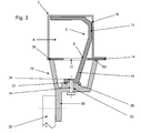
Fig. 3 eine schematische Schnittdarstellung entlang der Linie A - A inFig. 2 ; -
Fig. 4 eine schematische Darstellung einer zweiten Ausführungsform der Erfindung in Form einer Fahrzeugtür mit einer Befestigungseinrichtung für Rückspiegel; und -
Fig. 5 eine Schnittdarstellung entlang der Linie B - B inFig. 4 . - Die
Figuren 1 bis 3 zeigen schematisch eine erste Ausführungsform der Erfindung. Eine Fahrzeugtür 2 weist im oberen Fahrzeugtürrahmen 4 im Bereich der A-Säule einen rohrförmiger Hohlraum 6 auf. In dem Hohlraum 6 erstreckt sich ein Strukturteil 8, das ein sich im Hohlraum 6 erstreckendes, rinnenförmiges Teil 10 und ein sich durch eine Öffnung 12 in der Außenseite 14 der Fahrzeugtür 2 nach außen hervortretendes Teil 16 aufweist. Das rinnenförmige innere Teil 10 des Strukturteils 8 liegt an zwei im Winkel zueinander verlaufenden Innenseiten 18 und 20 des Hohlraums 6 abschnittsweise flächig an und ist mit den Innenseiten 18, 20 verschweißt. An dem freien Ende des äußeren Teils 16 des Strukturteils 8 ist eine erste Kontaktfläche 22 mit strukturierter Oberfläche ausgebildet. - In der ersten Kontaktfläche 22 ist eine Schraubaufnahme 24 vorgesehen. An dem freien Ende des äußeren Teils 16 des Strukturteils 8 lässt sich ein becherförmiger Haltebock 26 mit einem Becherrand und einem Becherboden montieren. Auf dem Becherboden ist eine zweite Kontaktfläche 28 ausgebildet, die eine zu der ersten Kontaktfläche 22 komplementäre Oberfläche aufweist, wodurch die beiden Kontaktflächen 22, 28 und damit Haltebock 26 und Strukturteil 8 zueinander positioniert werden. Auf dem Becherrand ist eine dritte Kontaktfläche 30 ausgebildet, die an der Außenseite 14 der Fahrzeugtür 2 anliegt. In dem Becherboden des Haltebocks 26 ist ein Schraubloch 32 ausgebildet, das die zweite Kontaktfläche 28 durchsetzt. In das Schraubloch 32 wird ein Verbindungselement in Form einer Verbindungsschraube 34 eingeführt und mit der Schraubaufnahme 24 in der ersten Kontaktfläche 22 verschraubt. Hierdurch wird der Haltebock 26 mit nur einer Schraube an dem Strukturteil 8 und damit an der Fahrzeugtür 2 befestigt.
- Der Haltebock weist ferner ein Trägerteil 36 auf, das sich von dem Becherboden weg erstreckt und an dem sich eine Einrichtung für indirekte Sicht, z. B. ein Rückspiegel 38, befestigen lässt. Der becherförmige Haltebock 26 überdeckt die Öffnung 12 in der Außenseite14 der Fahrzeugtür 2 und das daraus hervortretenden äußere Teil 16 des Strukturteils 8, so dass nur der Haltebock 26 zu sehen ist.
-
Fig. 4 und 5 zeigt eine zweite Ausführungsform der Erfindung, die im Wesentlichen den gleichen Aufbau wie die erste Ausführungsform aufweist. Der Unterschied zur ersten Ausführungsform besteht lediglich darin, dass das äußere Teil 16 des Strukturteils 8 einen vertikal noch oben stehenden Haltehaken 40 aufweist, an dem der Haltebock 26 mit Rückspiegel 38 bei der Montage eingehängt werden können. Auf diese Weise ist eine Ein-Mann-Montage möglich. - Das Strukturbauteil 8 kann ein Blechbauteil, das durch Stanzen und Biegen in die gewünschte Form gebracht wird, ein Kunststoffspritzgussbauteil, ein Druckgussbauteil, eine Hybridbauteil (Kunststoff-Metall-Verbund, Organoblech) oder ein geschäumtes Kunststoffbauteil sein. Das Strukturbauteil 8 kann mit den Innenseiten 18, 20 des Hohlraums 6 verschraubt, verschweißt, verklebt oder vernietet sein. Das innere Teil 10 des Strukturteils 8 kann sich in dem Hohlraum 8 über den gesamten Fahrzeugtürrahmen oder über einen Teil davon erstrecken. Das innere Teil 10 des Strukturteils 8 kann zusätzlich auch als Aggregateträger entsprechend der
DE 10 2005 014 570 A1 genutzt werden. - In einer nicht dargestellten alternativen Ausgestaltung der Erfindung ragt das Strukturteil nicht aus der Öffnung in der Außenseite der Fahrzeugtür heraus, sondern der Haltebock ragt durch die Öffnung in den Hohlraum hinein.
-
- 2
- Fahrzeugtür
- 4
- oberer Bereich von 2, Seite A-Säule
- 6
- Hohlraum
- 8
- Strukturteil
- 10
- inneres Teil von 8
- 12
- Öffnung in 2
- 14
- Außenseite von 2
- 16
- äußeres Teil von 8
- 18
- erste Innenseite von 6
- 20
- zweite Innenseite von 6
- 22
- erste Kontaktfläche
- 24
- Schraubaufnahme
- 26
- Haltebock
- 28
- zweite Kontaktfläche
- 30
- dritte Kontaktfläche
- 32
- Schraubloch
- 34
- Verbindungsschraube
- 36
- Trägerteil
- 38
- Einrichtung für indirekte Sicht, Rückspiegel
- 40
- Haltehaken
Claims (14)
- Bauteil (2), insbesondere Karosseriebauteil, mit wenigstens einem Hohlraum (6) und einer Befestigungseinrichtung zur Befestigung von externen Komponenten (38) an einer Außenseite (14) des Bauteils (2), mit
einem in dem wenigstens einen Hohlraum (6) befestigten Strukturelement (8), das eine durch eine Öffnung (12) in der Außenseite (14) des Bauteils zugängliche erste Kontaktfläche (22) aufweist,
gekennzeichnet durch
einen Haltebock (26), an dem die externe Komponente (38) befestigbar ist und der eine zweite und dritte Kontaktfläche (28, 30) aufweist,
wobei die zweite Kontaktfläche (28) an der ersten Kontaktfläche (22) anliegt und wobei die dritte Kontaktfläche (30) an der Außenseite (14) des Bauteils (2) anliegt, und
ein Verbindungselement (34) zur Verbindung von Strukturelement (8) und Haltebock (26) im Bereich von erster und zweiter Kontaktfläche (22, 28), wobei weiterhin bei einer Verbindung von Strukturelement (8) und Haltebock (26) mittels des Verbindungselements (34) der Haltebock (26) über die dritte Kontaktfläche (30) gegen die Außenseite (14) des Bauteils (2) verspannt ist. - Bauteil nach Anspruch 1, dadurch gekennzeichnet, dass das Strukturelement (8) zur Aussteifung des Bauteils (2) ausgelegt ist.
- Bauteil nach Anspruch 1 oder 2, dadurch gekennzeichnet, dass das Strukturelement (8) wenigstens abschnittsweise flächig an einer Innenseite (18, 20) des Hohlraums (6) befestigt ist.
- Bauteil nach einem der vorhergehenden Ansprüche, dadurch gekennzeichnet, dass das Verbindungselement (34) die erste und zweite Kontaktfläche (22, 28) durchsetzt.
- Bauteil nach einem der vorhergehenden Ansprüche, dadurch gekennzeichnet, dass das Verbindungselement eine Schraube (34) ist, die den Haltebock (26) im Bereich der zweiten Kontaktfläche (28) durchsetzt und in eine Schraubaufnahme (24) im Bereich der ersten Kontaktfläche (22) des Strukturelements (8) eingreift, wobei die erste und die zweite Kontaktfläche (22, 28) formschlüssig ineinander greifen.
- Bauteil nach einem der vorhergehenden Ansprüche, dadurch gekennzeichnet, dass der Haltebock (26) becherförmig mit einem Becherrand und einem Becherboden ausgebildet ist, wobei
der Becherrand die dritte Kontaktfläche (30) bildet und an der Außenseite (14) des Bauteils aufliegt, und
die zweite Kontaktfläche (28) auf dem Becherboden ausgebildet ist. - Bauteil nach einem der vorhergehenden Ansprüche, dadurch gekennzeichnet, dass ein aus der Öffnung (12) in der Außenseite (14) des Bauteils hervorstehendes Teil (16) des Strukturelements (8) hakenförmig ausgebildet ist und einen Haltehaken (40) für den Haltebock (26) bei der Montage aufweist.
- Bauteil nach einem der vorhergehenden Ansprüche, dadurch gekennzeichnet, dass über das Strukturelement (8) und den Haltebock (26) eine elektrische Verbindung zwischen der externen Komponente (38) und dem wenigstens einen Hohlraum (6) bereitgestellt ist.
- Bauteil nach einem der vorhergehenden Ansprüche, dadurch gekennzeichnet, dass sich das Strukturelement (8) in dem wenigstens einen Hohlraum (6) über einen Bereich des Hohlraums (6) erstreckt, der größer ist als die Öffnung (12) in der Außenseite (14) des Bauteils (2).
- Bauteil nach einem der vorhergehenden Ansprüche, dadurch gekennzeichnet, dass das Strukturelement als Blechbauteil, Kunststoffspritzgussbauteil, Druckgussbauteil, Hybridbauteil (Kunststoff-Metall-Verbund, Organoblech) oder geschäumtes Kunststoffbauteil ausgebildet ist.
- Bauteil nach einem der vorhergehenden Ansprüche, dadurch gekennzeichnet, dass ein in dem Hohlraum (6) liegendes inneres Teil (10) des Strukturteils (8) mit dem Bauteil (2) verschweißt, vernietet, verklebt oder verschraubt ist.
- Bauteil nach einem der vorhergehenden Ansprüche, dadurch gekennzeichnet, dass es eine Fahrzeugtür ist.
- Befestigungseinrichtung für ein Bauteil nach einem der vorhergehenden Ansprüche, mit
einem Strukturelement (8), das ein inneres Teil (10) umfasst, das in einem Hohlraum (6) anzuordnen ist, und einem äußeren Teil (16), das sich quer von dem inneren Teil (10) wegerstreckt und eine erste Kontaktfläche (22) aufweist,
einem Haltebock (26) an dem eine externe Komponente (38) befestigbar ist und der eine zweite und eine dritte Kontaktfläche (28, 30) aufweist,
wobei die zweite Kontaktfläche (28) an der ersten Kontaktfläche (22) anliegt und wobei die dritte Kontaktfläche (30) zur Anlage an einer Außenseite (14) des Bauteils (2) ausgelegt ist, und
einem Verbindungselement (34) zur Verbindung von Strukturelement (8) und Haltebock (26) im Bereich von erster und zweiter Kontaktfläche (22, 28), wobei bei einer Verbindung von Strukturelement (8) und Haltebock (26) mittels des Verbindungselements (34) der Haltebock (26) über die dritte Kontaktfläche (30) gegen die Außenseite (14) des Bauteils (2) verspannt ist. - Fahrzeug mit wenigstens einem Karosseriebauteil (2) nach einem der vorhergehenden Ansprüche und einer Einrichtung (38) für indirekte Sicht, die an dem Haltebock (26) befestigt ist.
Applications Claiming Priority (1)
| Application Number | Priority Date | Filing Date | Title |
|---|---|---|---|
| DE102011076198.5A DE102011076198B4 (de) | 2011-05-20 | 2011-05-20 | Befestigungseinrichtung für ein Bauteil, insbesondere Karosseriebauteil, zur Befestigung von externen Komponenten an einer Aussenseite des Bauteils sowie Fahrzeug mit einer solchen Befestigungseinrichtung |
Publications (2)
| Publication Number | Publication Date |
|---|---|
| EP2524831A1 true EP2524831A1 (de) | 2012-11-21 |
| EP2524831B1 EP2524831B1 (de) | 2016-05-04 |
Family
ID=46245808
Family Applications (1)
| Application Number | Title | Priority Date | Filing Date |
|---|---|---|---|
| EP12167610.0A Not-in-force EP2524831B1 (de) | 2011-05-20 | 2012-05-11 | Bauteil mit einer Befestigungseinrichtung zur Befestigung von externen Komponenten an einer Außenseite des Bauteils |
Country Status (4)
| Country | Link |
|---|---|
| EP (1) | EP2524831B1 (de) |
| BR (1) | BR102012011840B1 (de) |
| DE (1) | DE102011076198B4 (de) |
| ES (1) | ES2580954T3 (de) |
Citations (6)
| Publication number | Priority date | Publication date | Assignee | Title |
|---|---|---|---|---|
| GB2063412A (en) * | 1979-10-26 | 1981-06-03 | Nissan Motor | Retainer |
| JPH07215058A (ja) * | 1994-02-04 | 1995-08-15 | Araco Corp | 車両のドアフレーム構造 |
| DE19616788A1 (de) | 1996-04-26 | 1997-11-06 | Bayerische Motoren Werke Ag | Fahrzeugtür |
| EP1203678A2 (de) | 2000-11-03 | 2002-05-08 | Bayerische Motoren Werke Aktiengesellschaft | Gussteil als Krafteinleitungsstelle zur Befestigung einer tragenden Struktur für Karosseriebauteile |
| EP1598227A1 (de) * | 2004-05-18 | 2005-11-23 | DURA Automotive Plettenberg Entwicklungs- und Vertriebs GmbH | Rohbautür eines Fahrzeugs |
| DE102005014570A1 (de) | 2005-03-31 | 2006-10-05 | Man Nutzfahrzeuge Ag | Fahrzeugtür für ein Nutzfahrzeug |
Family Cites Families (2)
| Publication number | Priority date | Publication date | Assignee | Title |
|---|---|---|---|---|
| DE1480338A1 (de) * | 1965-07-01 | 1971-02-18 | Yorck Talbot | Haltevorrichtung fuer Kraftfahrzeug-Aussenrueckblickspiegel |
| DE2324452C3 (de) * | 1973-05-11 | 1975-10-02 | Yorck 1000 Berlin Talbot | Befestigungsvorrichtung für außen an der Karosserie eines Kraftfahrzeuges anzubringende Bau- oder Zubehörteile, insbesondere für AuBenrückblickspiegel |
-
2011
- 2011-05-20 DE DE102011076198.5A patent/DE102011076198B4/de not_active Expired - Fee Related
-
2012
- 2012-05-11 ES ES12167610.0T patent/ES2580954T3/es active Active
- 2012-05-11 EP EP12167610.0A patent/EP2524831B1/de not_active Not-in-force
- 2012-05-17 BR BR102012011840-8A patent/BR102012011840B1/pt not_active IP Right Cessation
Patent Citations (6)
| Publication number | Priority date | Publication date | Assignee | Title |
|---|---|---|---|---|
| GB2063412A (en) * | 1979-10-26 | 1981-06-03 | Nissan Motor | Retainer |
| JPH07215058A (ja) * | 1994-02-04 | 1995-08-15 | Araco Corp | 車両のドアフレーム構造 |
| DE19616788A1 (de) | 1996-04-26 | 1997-11-06 | Bayerische Motoren Werke Ag | Fahrzeugtür |
| EP1203678A2 (de) | 2000-11-03 | 2002-05-08 | Bayerische Motoren Werke Aktiengesellschaft | Gussteil als Krafteinleitungsstelle zur Befestigung einer tragenden Struktur für Karosseriebauteile |
| EP1598227A1 (de) * | 2004-05-18 | 2005-11-23 | DURA Automotive Plettenberg Entwicklungs- und Vertriebs GmbH | Rohbautür eines Fahrzeugs |
| DE102005014570A1 (de) | 2005-03-31 | 2006-10-05 | Man Nutzfahrzeuge Ag | Fahrzeugtür für ein Nutzfahrzeug |
Also Published As
| Publication number | Publication date |
|---|---|
| BR102012011840A8 (pt) | 2018-04-17 |
| DE102011076198B4 (de) | 2015-10-08 |
| ES2580954T3 (es) | 2016-08-30 |
| EP2524831B1 (de) | 2016-05-04 |
| BR102012011840B1 (pt) | 2020-12-08 |
| DE102011076198A1 (de) | 2012-11-22 |
| BR102012011840A2 (pt) | 2014-04-01 |
Similar Documents
| Publication | Publication Date | Title |
|---|---|---|
| DE19925840B4 (de) | Karosserieteil für Kraftfahrzeuge sowie Verfahren zu dessen Herstellung | |
| EP2496428B1 (de) | Strukturrahmenmodul für eine fahrzeugtür | |
| DE102013018079A1 (de) | Scharnier für ein Kraftfahrzeug | |
| DE102010036475B4 (de) | Stoßfängeraufsatz, Stoßfängeranordnung und Kraftfahrzeug | |
| DE19962988A1 (de) | Fahrzeugtür und Montageverfahren für eine Fahrzeugtür | |
| DE102010060488A1 (de) | Kraftfahrzeug mit einem Außenrückspiegel | |
| EP1517808B1 (de) | Kraftfahrzeugtür mit einer von dem modulträger gehaltenen fensterhebeschiene | |
| EP2977298B1 (de) | Frontendmodul | |
| DE102011051699A1 (de) | Kraftfahrzeug | |
| DE102005012969B4 (de) | Verstärkungsaufbau für Türfensterscheibenführung | |
| DE102005014570B4 (de) | Fahrzeugtür für ein Nutzfahrzeug | |
| EP2524831B1 (de) | Bauteil mit einer Befestigungseinrichtung zur Befestigung von externen Komponenten an einer Außenseite des Bauteils | |
| DE102009036714A1 (de) | Karosserieabschnitt einer Rohbaukarosserie eines Kraftfahrzeuges | |
| DE10351446B4 (de) | Gewindeplatte | |
| DE102012023588A1 (de) | Verbindungsanordnung eines Türmoduls an einem Rohbauteil einer Tür eines Kraftwagens | |
| DE19711598B4 (de) | Kraftfahrzeugtür | |
| DE19821077B4 (de) | Fahrzeugtür | |
| DE102010036985A1 (de) | Deformationselement | |
| EP2368760B1 (de) | Träger für eine Sondersignalanlage für einen Dach eines Kraftfahrzeugs | |
| EP3536653B1 (de) | Flurförderzeug mit einem hydraulikflüssigkeitstank | |
| DE102008010490A1 (de) | Emblemanordnung | |
| EP2289772B1 (de) | Vorrichtung zur Verbindung eines Trägerlements mit einem Gussbauteil | |
| DE10354293B4 (de) | Träger für eine Tragstruktur | |
| DE10024454A1 (de) | Vorrichtung zur Befestigung des Außenspiegels an der Seitentür eines Kraftfahrzeugs | |
| DE102023119721B3 (de) | Seitenaufprallverstärkung einer Fahrzeugkarosserie |
Legal Events
| Date | Code | Title | Description |
|---|---|---|---|
| PUAI | Public reference made under article 153(3) epc to a published international application that has entered the european phase |
Free format text: ORIGINAL CODE: 0009012 |
|
| AK | Designated contracting states |
Kind code of ref document: A1 Designated state(s): AL AT BE BG CH CY CZ DE DK EE ES FI FR GB GR HR HU IE IS IT LI LT LU LV MC MK MT NL NO PL PT RO RS SE SI SK SM TR |
|
| AX | Request for extension of the european patent |
Extension state: BA ME |
|
| 17P | Request for examination filed |
Effective date: 20130130 |
|
| GRAP | Despatch of communication of intention to grant a patent |
Free format text: ORIGINAL CODE: EPIDOSNIGR1 |
|
| INTG | Intention to grant announced |
Effective date: 20151013 |
|
| GRAS | Grant fee paid |
Free format text: ORIGINAL CODE: EPIDOSNIGR3 |
|
| GRAR | Information related to intention to grant a patent recorded |
Free format text: ORIGINAL CODE: EPIDOSNIGR71 |
|
| GRAA | (expected) grant |
Free format text: ORIGINAL CODE: 0009210 |
|
| RAP1 | Party data changed (applicant data changed or rights of an application transferred) |
Owner name: MEKRA LANG GMBH & CO. KG |
|
| INTG | Intention to grant announced |
Effective date: 20160316 |
|
| AK | Designated contracting states |
Kind code of ref document: B1 Designated state(s): AL AT BE BG CH CY CZ DE DK EE ES FI FR GB GR HR HU IE IS IT LI LT LU LV MC MK MT NL NO PL PT RO RS SE SI SK SM TR |
|
| REG | Reference to a national code |
Ref country code: GB Ref legal event code: FG4D Free format text: NOT ENGLISH |
|
| REG | Reference to a national code |
Ref country code: CH Ref legal event code: EP |
|
| REG | Reference to a national code |
Ref country code: AT Ref legal event code: REF Ref document number: 796579 Country of ref document: AT Kind code of ref document: T Effective date: 20160515 |
|
| REG | Reference to a national code |
Ref country code: IE Ref legal event code: FG4D Free format text: LANGUAGE OF EP DOCUMENT: GERMAN |
|
| REG | Reference to a national code |
Ref country code: DE Ref legal event code: R096 Ref document number: 502012006981 Country of ref document: DE |
|
| REG | Reference to a national code |
Ref country code: FR Ref legal event code: PLFP Year of fee payment: 5 |
|
| REG | Reference to a national code |
Ref country code: SE Ref legal event code: TRGR |
|
| REG | Reference to a national code |
Ref country code: NL Ref legal event code: FP |
|
| REG | Reference to a national code |
Ref country code: ES Ref legal event code: FG2A Ref document number: 2580954 Country of ref document: ES Kind code of ref document: T3 Effective date: 20160830 |
|
| REG | Reference to a national code |
Ref country code: LT Ref legal event code: MG4D |
|
| PG25 | Lapsed in a contracting state [announced via postgrant information from national office to epo] |
Ref country code: LT Free format text: LAPSE BECAUSE OF FAILURE TO SUBMIT A TRANSLATION OF THE DESCRIPTION OR TO PAY THE FEE WITHIN THE PRESCRIBED TIME-LIMIT Effective date: 20160504 Ref country code: FI Free format text: LAPSE BECAUSE OF FAILURE TO SUBMIT A TRANSLATION OF THE DESCRIPTION OR TO PAY THE FEE WITHIN THE PRESCRIBED TIME-LIMIT Effective date: 20160504 Ref country code: NO Free format text: LAPSE BECAUSE OF FAILURE TO SUBMIT A TRANSLATION OF THE DESCRIPTION OR TO PAY THE FEE WITHIN THE PRESCRIBED TIME-LIMIT Effective date: 20160804 |
|
| PG25 | Lapsed in a contracting state [announced via postgrant information from national office to epo] |
Ref country code: HR Free format text: LAPSE BECAUSE OF FAILURE TO SUBMIT A TRANSLATION OF THE DESCRIPTION OR TO PAY THE FEE WITHIN THE PRESCRIBED TIME-LIMIT Effective date: 20160504 Ref country code: RS Free format text: LAPSE BECAUSE OF FAILURE TO SUBMIT A TRANSLATION OF THE DESCRIPTION OR TO PAY THE FEE WITHIN THE PRESCRIBED TIME-LIMIT Effective date: 20160504 Ref country code: PT Free format text: LAPSE BECAUSE OF FAILURE TO SUBMIT A TRANSLATION OF THE DESCRIPTION OR TO PAY THE FEE WITHIN THE PRESCRIBED TIME-LIMIT Effective date: 20160905 Ref country code: LV Free format text: LAPSE BECAUSE OF FAILURE TO SUBMIT A TRANSLATION OF THE DESCRIPTION OR TO PAY THE FEE WITHIN THE PRESCRIBED TIME-LIMIT Effective date: 20160504 Ref country code: GR Free format text: LAPSE BECAUSE OF FAILURE TO SUBMIT A TRANSLATION OF THE DESCRIPTION OR TO PAY THE FEE WITHIN THE PRESCRIBED TIME-LIMIT Effective date: 20160805 |
|
| PG25 | Lapsed in a contracting state [announced via postgrant information from national office to epo] |
Ref country code: BE Free format text: LAPSE BECAUSE OF NON-PAYMENT OF DUE FEES Effective date: 20160531 |
|
| REG | Reference to a national code |
Ref country code: CH Ref legal event code: PL |
|
| PG25 | Lapsed in a contracting state [announced via postgrant information from national office to epo] |
Ref country code: LI Free format text: LAPSE BECAUSE OF NON-PAYMENT OF DUE FEES Effective date: 20160531 Ref country code: CZ Free format text: LAPSE BECAUSE OF FAILURE TO SUBMIT A TRANSLATION OF THE DESCRIPTION OR TO PAY THE FEE WITHIN THE PRESCRIBED TIME-LIMIT Effective date: 20160504 Ref country code: CH Free format text: LAPSE BECAUSE OF NON-PAYMENT OF DUE FEES Effective date: 20160531 Ref country code: RO Free format text: LAPSE BECAUSE OF FAILURE TO SUBMIT A TRANSLATION OF THE DESCRIPTION OR TO PAY THE FEE WITHIN THE PRESCRIBED TIME-LIMIT Effective date: 20160504 Ref country code: DK Free format text: LAPSE BECAUSE OF FAILURE TO SUBMIT A TRANSLATION OF THE DESCRIPTION OR TO PAY THE FEE WITHIN THE PRESCRIBED TIME-LIMIT Effective date: 20160504 Ref country code: SK Free format text: LAPSE BECAUSE OF FAILURE TO SUBMIT A TRANSLATION OF THE DESCRIPTION OR TO PAY THE FEE WITHIN THE PRESCRIBED TIME-LIMIT Effective date: 20160504 Ref country code: EE Free format text: LAPSE BECAUSE OF FAILURE TO SUBMIT A TRANSLATION OF THE DESCRIPTION OR TO PAY THE FEE WITHIN THE PRESCRIBED TIME-LIMIT Effective date: 20160504 |
|
| REG | Reference to a national code |
Ref country code: DE Ref legal event code: R097 Ref document number: 502012006981 Country of ref document: DE |
|
| REG | Reference to a national code |
Ref country code: IE Ref legal event code: MM4A |
|
| PG25 | Lapsed in a contracting state [announced via postgrant information from national office to epo] |
Ref country code: SM Free format text: LAPSE BECAUSE OF FAILURE TO SUBMIT A TRANSLATION OF THE DESCRIPTION OR TO PAY THE FEE WITHIN THE PRESCRIBED TIME-LIMIT Effective date: 20160504 Ref country code: PL Free format text: LAPSE BECAUSE OF FAILURE TO SUBMIT A TRANSLATION OF THE DESCRIPTION OR TO PAY THE FEE WITHIN THE PRESCRIBED TIME-LIMIT Effective date: 20160504 |
|
| PLBE | No opposition filed within time limit |
Free format text: ORIGINAL CODE: 0009261 |
|
| STAA | Information on the status of an ep patent application or granted ep patent |
Free format text: STATUS: NO OPPOSITION FILED WITHIN TIME LIMIT |
|
| PG25 | Lapsed in a contracting state [announced via postgrant information from national office to epo] |
Ref country code: MC Free format text: LAPSE BECAUSE OF FAILURE TO SUBMIT A TRANSLATION OF THE DESCRIPTION OR TO PAY THE FEE WITHIN THE PRESCRIBED TIME-LIMIT Effective date: 20160504 |
|
| 26N | No opposition filed |
Effective date: 20170207 |
|
| REG | Reference to a national code |
Ref country code: FR Ref legal event code: PLFP Year of fee payment: 6 |
|
| PG25 | Lapsed in a contracting state [announced via postgrant information from national office to epo] |
Ref country code: SI Free format text: LAPSE BECAUSE OF FAILURE TO SUBMIT A TRANSLATION OF THE DESCRIPTION OR TO PAY THE FEE WITHIN THE PRESCRIBED TIME-LIMIT Effective date: 20160504 Ref country code: IE Free format text: LAPSE BECAUSE OF NON-PAYMENT OF DUE FEES Effective date: 20160511 |
|
| PGFP | Annual fee paid to national office [announced via postgrant information from national office to epo] |
Ref country code: NL Payment date: 20170522 Year of fee payment: 6 |
|
| PGFP | Annual fee paid to national office [announced via postgrant information from national office to epo] |
Ref country code: FR Payment date: 20170522 Year of fee payment: 6 Ref country code: GB Payment date: 20170524 Year of fee payment: 6 |
|
| PGFP | Annual fee paid to national office [announced via postgrant information from national office to epo] |
Ref country code: SE Payment date: 20170523 Year of fee payment: 6 Ref country code: IT Payment date: 20170524 Year of fee payment: 6 Ref country code: ES Payment date: 20170601 Year of fee payment: 6 |
|
| PG25 | Lapsed in a contracting state [announced via postgrant information from national office to epo] |
Ref country code: CY Free format text: LAPSE BECAUSE OF FAILURE TO SUBMIT A TRANSLATION OF THE DESCRIPTION OR TO PAY THE FEE WITHIN THE PRESCRIBED TIME-LIMIT Effective date: 20160504 Ref country code: HU Free format text: LAPSE BECAUSE OF FAILURE TO SUBMIT A TRANSLATION OF THE DESCRIPTION OR TO PAY THE FEE WITHIN THE PRESCRIBED TIME-LIMIT; INVALID AB INITIO Effective date: 20120511 |
|
| PG25 | Lapsed in a contracting state [announced via postgrant information from national office to epo] |
Ref country code: IS Free format text: LAPSE BECAUSE OF FAILURE TO SUBMIT A TRANSLATION OF THE DESCRIPTION OR TO PAY THE FEE WITHIN THE PRESCRIBED TIME-LIMIT Effective date: 20160504 Ref country code: LU Free format text: LAPSE BECAUSE OF NON-PAYMENT OF DUE FEES Effective date: 20160511 Ref country code: MT Free format text: LAPSE BECAUSE OF FAILURE TO SUBMIT A TRANSLATION OF THE DESCRIPTION OR TO PAY THE FEE WITHIN THE PRESCRIBED TIME-LIMIT Effective date: 20160504 Ref country code: MK Free format text: LAPSE BECAUSE OF FAILURE TO SUBMIT A TRANSLATION OF THE DESCRIPTION OR TO PAY THE FEE WITHIN THE PRESCRIBED TIME-LIMIT Effective date: 20160504 Ref country code: TR Free format text: LAPSE BECAUSE OF FAILURE TO SUBMIT A TRANSLATION OF THE DESCRIPTION OR TO PAY THE FEE WITHIN THE PRESCRIBED TIME-LIMIT Effective date: 20160504 |
|
| REG | Reference to a national code |
Ref country code: AT Ref legal event code: MM01 Ref document number: 796579 Country of ref document: AT Kind code of ref document: T Effective date: 20170511 |
|
| PG25 | Lapsed in a contracting state [announced via postgrant information from national office to epo] |
Ref country code: BG Free format text: LAPSE BECAUSE OF FAILURE TO SUBMIT A TRANSLATION OF THE DESCRIPTION OR TO PAY THE FEE WITHIN THE PRESCRIBED TIME-LIMIT Effective date: 20160504 |
|
| PG25 | Lapsed in a contracting state [announced via postgrant information from national office to epo] |
Ref country code: AT Free format text: LAPSE BECAUSE OF NON-PAYMENT OF DUE FEES Effective date: 20170511 |
|
| PG25 | Lapsed in a contracting state [announced via postgrant information from national office to epo] |
Ref country code: AL Free format text: LAPSE BECAUSE OF FAILURE TO SUBMIT A TRANSLATION OF THE DESCRIPTION OR TO PAY THE FEE WITHIN THE PRESCRIBED TIME-LIMIT Effective date: 20160504 |
|
| REG | Reference to a national code |
Ref country code: SE Ref legal event code: EUG Ref country code: NL Ref legal event code: MM Effective date: 20180601 |
|
| GBPC | Gb: european patent ceased through non-payment of renewal fee |
Effective date: 20180511 |
|
| PG25 | Lapsed in a contracting state [announced via postgrant information from national office to epo] |
Ref country code: SE Free format text: LAPSE BECAUSE OF NON-PAYMENT OF DUE FEES Effective date: 20180512 |
|
| PG25 | Lapsed in a contracting state [announced via postgrant information from national office to epo] |
Ref country code: GB Free format text: LAPSE BECAUSE OF NON-PAYMENT OF DUE FEES Effective date: 20180511 Ref country code: NL Free format text: LAPSE BECAUSE OF NON-PAYMENT OF DUE FEES Effective date: 20180601 Ref country code: FR Free format text: LAPSE BECAUSE OF NON-PAYMENT OF DUE FEES Effective date: 20180531 Ref country code: IT Free format text: LAPSE BECAUSE OF NON-PAYMENT OF DUE FEES Effective date: 20180511 |
|
| REG | Reference to a national code |
Ref country code: ES Ref legal event code: FD2A Effective date: 20190913 |
|
| PG25 | Lapsed in a contracting state [announced via postgrant information from national office to epo] |
Ref country code: ES Free format text: LAPSE BECAUSE OF NON-PAYMENT OF DUE FEES Effective date: 20180512 |
|
| PGFP | Annual fee paid to national office [announced via postgrant information from national office to epo] |
Ref country code: DE Payment date: 20200511 Year of fee payment: 9 |
|
| REG | Reference to a national code |
Ref country code: DE Ref legal event code: R119 Ref document number: 502012006981 Country of ref document: DE |
|
| PG25 | Lapsed in a contracting state [announced via postgrant information from national office to epo] |
Ref country code: DE Free format text: LAPSE BECAUSE OF NON-PAYMENT OF DUE FEES Effective date: 20211201 |