EP2521507B1 - Uncalibrated visual servoing using real-time velocity optimization - Google Patents
Uncalibrated visual servoing using real-time velocity optimization Download PDFInfo
- Publication number
- EP2521507B1 EP2521507B1 EP10793050.5A EP10793050A EP2521507B1 EP 2521507 B1 EP2521507 B1 EP 2521507B1 EP 10793050 A EP10793050 A EP 10793050A EP 2521507 B1 EP2521507 B1 EP 2521507B1
- Authority
- EP
- European Patent Office
- Prior art keywords
- tracking
- robotic
- effector
- robot
- vector
- Prior art date
- Legal status (The legal status is an assumption and is not a legal conclusion. Google has not performed a legal analysis and makes no representation as to the accuracy of the status listed.)
- Active
Links
- 230000000007 visual effect Effects 0.000 title claims description 46
- 238000005457 optimization Methods 0.000 title description 4
- 239000013598 vector Substances 0.000 claims description 118
- 239000012636 effector Substances 0.000 claims description 62
- 238000000034 method Methods 0.000 claims description 61
- 230000033001 locomotion Effects 0.000 claims description 23
- 238000013507 mapping Methods 0.000 claims description 18
- 230000003287 optical effect Effects 0.000 claims description 17
- 238000005070 sampling Methods 0.000 claims description 11
- 239000000523 sample Substances 0.000 claims description 3
- 230000008569 process Effects 0.000 description 23
- 238000003780 insertion Methods 0.000 description 13
- 230000037431 insertion Effects 0.000 description 13
- 238000003384 imaging method Methods 0.000 description 7
- 210000000056 organ Anatomy 0.000 description 5
- 230000033228 biological regulation Effects 0.000 description 4
- 230000001276 controlling effect Effects 0.000 description 4
- 238000006073 displacement reaction Methods 0.000 description 4
- 230000008859 change Effects 0.000 description 3
- 230000003247 decreasing effect Effects 0.000 description 3
- 238000011156 evaluation Methods 0.000 description 3
- 230000006641 stabilisation Effects 0.000 description 3
- 238000011105 stabilization Methods 0.000 description 3
- 206010044565 Tremor Diseases 0.000 description 2
- 230000003044 adaptive effect Effects 0.000 description 2
- 230000004075 alteration Effects 0.000 description 2
- 210000003484 anatomy Anatomy 0.000 description 2
- 238000013459 approach Methods 0.000 description 2
- 230000008901 benefit Effects 0.000 description 2
- 210000004204 blood vessel Anatomy 0.000 description 2
- 238000007675 cardiac surgery Methods 0.000 description 2
- 238000010276 construction Methods 0.000 description 2
- 238000002674 endoscopic surgery Methods 0.000 description 2
- 238000002324 minimally invasive surgery Methods 0.000 description 2
- 238000012986 modification Methods 0.000 description 2
- 230000004048 modification Effects 0.000 description 2
- 238000000926 separation method Methods 0.000 description 2
- 230000003068 static effect Effects 0.000 description 2
- 238000001356 surgical procedure Methods 0.000 description 2
- 238000012084 abdominal surgery Methods 0.000 description 1
- 238000010009 beating Methods 0.000 description 1
- 238000002192 cholecystectomy Methods 0.000 description 1
- 238000004590 computer program Methods 0.000 description 1
- 210000004351 coronary vessel Anatomy 0.000 description 1
- 238000009795 derivation Methods 0.000 description 1
- 238000001839 endoscopy Methods 0.000 description 1
- 239000000835 fiber Substances 0.000 description 1
- 238000002357 laparoscopic surgery Methods 0.000 description 1
- 239000003550 marker Substances 0.000 description 1
- 238000012978 minimally invasive surgical procedure Methods 0.000 description 1
- 210000004115 mitral valve Anatomy 0.000 description 1
- 230000010355 oscillation Effects 0.000 description 1
- 230000008447 perception Effects 0.000 description 1
- 238000012545 processing Methods 0.000 description 1
- 238000011471 prostatectomy Methods 0.000 description 1
- 230000001105 regulatory effect Effects 0.000 description 1
- 230000009466 transformation Effects 0.000 description 1
Images


Classifications
-
- B—PERFORMING OPERATIONS; TRANSPORTING
- B25—HAND TOOLS; PORTABLE POWER-DRIVEN TOOLS; MANIPULATORS
- B25J—MANIPULATORS; CHAMBERS PROVIDED WITH MANIPULATION DEVICES
- B25J9/00—Programme-controlled manipulators
- B25J9/16—Programme controls
- B25J9/1694—Programme controls characterised by use of sensors other than normal servo-feedback from position, speed or acceleration sensors, perception control, multi-sensor controlled systems, sensor fusion
- B25J9/1697—Vision controlled systems
-
- A—HUMAN NECESSITIES
- A61—MEDICAL OR VETERINARY SCIENCE; HYGIENE
- A61B—DIAGNOSIS; SURGERY; IDENTIFICATION
- A61B34/00—Computer-aided surgery; Manipulators or robots specially adapted for use in surgery
- A61B34/30—Surgical robots
-
- G—PHYSICS
- G06—COMPUTING; CALCULATING OR COUNTING
- G06T—IMAGE DATA PROCESSING OR GENERATION, IN GENERAL
- G06T7/00—Image analysis
- G06T7/20—Analysis of motion
- G06T7/246—Analysis of motion using feature-based methods, e.g. the tracking of corners or segments
-
- A—HUMAN NECESSITIES
- A61—MEDICAL OR VETERINARY SCIENCE; HYGIENE
- A61B—DIAGNOSIS; SURGERY; IDENTIFICATION
- A61B34/00—Computer-aided surgery; Manipulators or robots specially adapted for use in surgery
- A61B34/20—Surgical navigation systems; Devices for tracking or guiding surgical instruments, e.g. for frameless stereotaxis
-
- A—HUMAN NECESSITIES
- A61—MEDICAL OR VETERINARY SCIENCE; HYGIENE
- A61B—DIAGNOSIS; SURGERY; IDENTIFICATION
- A61B90/00—Instruments, implements or accessories specially adapted for surgery or diagnosis and not covered by any of the groups A61B1/00 - A61B50/00, e.g. for luxation treatment or for protecting wound edges
- A61B90/36—Image-producing devices or illumination devices not otherwise provided for
- A61B90/361—Image-producing devices, e.g. surgical cameras
-
- G—PHYSICS
- G06—COMPUTING; CALCULATING OR COUNTING
- G06T—IMAGE DATA PROCESSING OR GENERATION, IN GENERAL
- G06T2207/00—Indexing scheme for image analysis or image enhancement
- G06T2207/10—Image acquisition modality
- G06T2207/10068—Endoscopic image
-
- Y—GENERAL TAGGING OF NEW TECHNOLOGICAL DEVELOPMENTS; GENERAL TAGGING OF CROSS-SECTIONAL TECHNOLOGIES SPANNING OVER SEVERAL SECTIONS OF THE IPC; TECHNICAL SUBJECTS COVERED BY FORMER USPC CROSS-REFERENCE ART COLLECTIONS [XRACs] AND DIGESTS
- Y10—TECHNICAL SUBJECTS COVERED BY FORMER USPC
- Y10S—TECHNICAL SUBJECTS COVERED BY FORMER USPC CROSS-REFERENCE ART COLLECTIONS [XRACs] AND DIGESTS
- Y10S901/00—Robots
- Y10S901/14—Arm movement, spatial
- Y10S901/15—Jointed arm
-
- Y—GENERAL TAGGING OF NEW TECHNOLOGICAL DEVELOPMENTS; GENERAL TAGGING OF CROSS-SECTIONAL TECHNOLOGIES SPANNING OVER SEVERAL SECTIONS OF THE IPC; TECHNICAL SUBJECTS COVERED BY FORMER USPC CROSS-REFERENCE ART COLLECTIONS [XRACs] AND DIGESTS
- Y10—TECHNICAL SUBJECTS COVERED BY FORMER USPC
- Y10S—TECHNICAL SUBJECTS COVERED BY FORMER USPC CROSS-REFERENCE ART COLLECTIONS [XRACs] AND DIGESTS
- Y10S901/00—Robots
- Y10S901/46—Sensing device
- Y10S901/47—Optical
Definitions
- the present invention generally relates to a visual servoing of a robot during a robotic procedure.
- the present invention specifically relates to a visual servoing of an endoscopic robot during a minimally invasive surgery.
- a minimally invasive surgery utilizes an endoscope, which is a long, flexible or rigid tube having an imaging capability.
- the endoscope Upon insertion into a body through a natural orifice or a small incision, the endoscope provides an image of the region of interest that may be viewed through an eyepiece or on a screen as a surgeon performs the operation.
- Visual servoing is a robot control method using a visual input (images) to set robot movement parameters. This method is used for robotic following of targets, for autonomous robots, etc.
- visual servoing is used in the control loops with medical images to guide robots towards some specific anatomical (e.g., organs) or surgical targets (e.g., instruments).
- a standard imaging modality for visual servoing in this domain is a rigid endoscope. The camera feed of the endoscope is connected to the robot control loop providing steering information.
- Image Jacobian a mathematical transformation between image coordinates and robotic joint space has to be established (referred to as Image Jacobian).
- the entire process is referred to as the system calibration and requires various steps such as camera calibration and robot calibration.
- camera calibration and robot calibration steps such as camera calibration and robot calibration.
- depth between the camera and the organ/object under consideration needs to be measured either from images or from using special sensors.
- camera calibration is a process to establish inherent camera parameters such as, for example, the optical center of the image, focal lengths in both directions and the pixel size. This is usually done preoperatively and involves acquisition of several images of a calibration object (usually a chessboard-like object) and computation of parameters from those images. If some of the parameters are changed during the surgery (e.g., camera focus is changed), then the camera calibration needs to be repeated.
- Robot calibration is a process of establishing the mathematical relation between the joint space of the robot and the end-effector, an endoscope in this domain. This process is a straightforward procedure, well established in practice. However, it usually requires a technical expert to perform the calibration. If the user/surgeon moves an endoscope relative to the robot, then the robot calibration needs to be repeated.
- the International Patent Application WO2009/045827 discloses a method and system for tool locating and tool tracking in robotic surgical systems. This includes generating kinematics information for the robotic instrument within a field of view of a camera, capturing image information in the field of view of the camera and adaptively fusing the kinematics information and the image information together to determine pose information of the robotic instrument.
- the present invention provides a visual servoing technique that does not rely on Image Jacobian or depth perception from endoscopy images. More particularly, the visual servoing technique of the present invention involves a robot holding an endoscope that eliminates the need for calibrating the endoscope or for obtaining relative position of the endoscope image to the robot.
- the visual servoing technique of the present invention further allows a robotic system to be used with a standard endoscope without any adjustments to the hardware and without additional procedures in the surgery workflow.
- the visual servoing of the present invention further allows an intra-operative change of endoscopes (e.g., forward looking to oblique or vice versa).
- One form of the present invention is a robotic system employing a camera (e.g., an endoscope), a robot and a robot controller.
- the camera has an optical view (e.g., forward or oblique) for acquiring a digital video frame illustrating an image.
- the robot includes an end-effector and one or more joints for maneuvering the end-effector.
- the robot controller includes a visual servo for controlling a pose of the end-effector relative to an image feature within the digital video frame.
- the visual servo identifies a tracking vector within an image coordinate system of the digital video frame extending from a tracking point to a target point associated with the image feature, maps the tracking vector within a configuration space constructed from a robotic coordinate system associated with the end-effector, and derives a pose of the end-effector within the robotic coordinate system from the mapping of the tracking vector within the configuration space.
- a second form of the present invention is a robotic control method including a camera having an optical view and a robot having an end-effector and one or more joints for maneuvering the end-effector.
- the robotic control method involves an acquisition of a digital video frame illustrating an image as optically viewed by the camera, and an execution of a visual servoing for controlling a pose of the end-effector relative to an image feature within the digital video frame.
- the visual servoing involves an identification of a tracking vector within an image coordinate system of the digital video frame extending from a tracking point to a target point associated with the image feature, a mapping of the tracking vector within a configuration space constructed from a robotic coordinate system associated with the end-effector, and a derivation of a pose of the end-effector within the robotic coordinate system from the mapping of the tracking vector within the configuration space.
- a robotic system 20 employs a camera 30, a robot 40 and a robot controller 50 for any robotic procedure involving automatic motion capability of robot 40.
- robotic procedures include, but are not limited to, medical procedures, assembly line procedures and procedures involving mobile robots.
- robotic system 20 may be utilized for medical procedures including, but are not limited to, minimally invasive cardiac surgery (e.g., coronary artery bypass grafting or mitral valve replacement), minimally invasive abdominal surgery (laparoscopy) (e.g., prostatectomy or cholecystectomy), and natural orifice translumenal endoscopic surgery.
- Camera 30 may be any type of camera having a forward optical view or an oblique optical view, and employing a frame grabber 31 of any type that is capable of acquiring a sequence of two-dimensional digital video frames 32 at a predefined frame rate (e.g., 30 frames per second).
- camera 30 is an endoscope broadly defined herein as any device structurally configured for imaging an anatomical region of a body (e.g., human or animal) via an imaging device (e.g., fiber optics, lenses, miniaturized CCD based imaging systems, etc) having a forward optical view or an oblique optical view and employing a digital frame grabber capable of providing each digital video frame 32 to robot controller 50.
- an imaging device e.g., fiber optics, lenses, miniaturized CCD based imaging systems, etc
- the endoscope examples include, but are not limited to, any type of imaging scope (e.g., a bronchoscope, a colonoscope, a laparoscope, an arthroscope, etc.) and any device similar to a scope that is equipped with an image system (e.g., an imaging cannula).
- imaging scope e.g., a bronchoscope, a colonoscope, a laparoscope, an arthroscope, etc.
- an imaging cannula e.g., an imaging cannula
- Robot 40 is broadly defined herein as any robotic device structurally configured with motorized control of one or more joints 41 for maneuvering an end-effector 42 of robot 40 as desired for the particular robotic procedure.
- robot 40 may have a minimum of four (4) degrees-of-freedom, preferably six (6) or seven (7) degrees-of-freedom.
- a pose of end-effector 42 is a position and an orientation of end-effector 42 within a coordinate system of robot 40, and any given pose of end-effector 42 dictates a pose of the optical view of camera 40 within the coordinate system of robot 40.
- camera 30 may be mounted to end-effector 42 (e.g., an endoscope mounted on robot 40 for providing a view of an anatomical region of a body during a medical procedure).
- robot 40 may allow for any provisory orientation of camera 30 (e.g., an intra-operative manual rotation of camera 30 about a longitudinal axis of camera 30).
- robot 40 may have a specific joint for rotating camera 30 about a longitudinal axis of camera 30.
- Robot controller 50 is broadly defined herein as any controller structurally configured to provide one or more robot control commands (“RCC") 52 to robot 40 for controlling a pose of end-effector 42 as desired for a particular robotic procedure by commanding definitive movements of each robotic joint(s) 41 as needed to achieve the desired pose of end-effector 42.
- RRC robot control commands
- robot control command(s) 52 may move one or more robotic joint(s) 41 as needed for facilitating a tracking of an instrument tip of a surgical tool by the endoscope to provide a consistent view of the tip for a surgeon, or for steering the endoscope toward a specific anatomical feature such as blood vessels in cardiac surgery, or for coinciding physiological movement of the endoscope with an organ to provide a stable image of an anatomical view of the organ.
- robot controller 50 For robotic tracking of a feature of an image within digital video frames 32, robot controller 50 includes a visual servo 51 for controlling the pose of end-effector 42 relative to a feature of an image within each digital video frame 32.
- visual servo 51 implements a static or dynamic robotic tracking of a defined target point (e.g., one or more pixels) of a particular image feature within digital video frames 32 by an execution of an adaptive algorithm that automatically identifies a tracking vector extending from a tracking point (e.g., one or more pixels) to the target point within digital video frames 32.
- the adaptive algorithm updates the tracking vector as needed for each digital video frame 32 or at any specified frame-rate of digital video frames 32.
- visual servo 51 implements a feature tracking process 53, a direction setting process 55 and an inverse kinematics process 57 in a closed robot control loop 21 with an image acquisition 33 implemented by frame grabber 31 and controlled movement(s) 43 of robotic joint(s) 41.
- processes 53, 55 and 57 may be implemented by modules of visual servo 51 (not shown) that are embodied by hardware, software and/or firmware installed on any platform (e.g., a general computer, ASIC board, etc.)
- feature tracking process 53 involves an individual processing of each digital video frame 32 to identify the target point of a particular image feature within digital video frames 32 as known in the art.
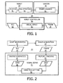
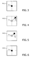
- FIGS. 3-6 show four (4) digital video frames 32 of a target point TG of a particular image feature symbolized by a black X.
- the particular feature may be an instrument tip of a surgical tool with camera 30 being an endoscope for providing a consistent view of the tip for a surgeon, or the particular feature may be a definitive portion of a specific anatomical feature such as blood vessels or an organ.
- feature tracking 53 generates two-dimensional image data ("2DID") 54 indicating the tracked movements of the target point within each digital video frame 32, and direction setting process 55 in turn processes 2D data 54 to identify a tracking vector (e.g., tracking direction and a tracking speed) extending from a tracking point to the target point for each digital video frame 32.
- the identification of the tracking vector sets a fixed tracking direction extending from the tracking point to the target point, and sets a tracking speed that may also be fixed or alternatively adjusted to optimize a tracking of the target point.
- direction setting process 55 For each digital video frame 32 having a tracking vector of any magnitude or of a minimum magnitude, direction setting process 55 generates three-dimensional robot data ("3DRD") 56 indicating the desired pose of end-effector 42 of robot 40 relative to the image feature within digital video frames 32.
- Inverse kinematics process 57 processes 3D data 56 as known in the art for generating one or more robot control command(s) 52 as needed for the appropriate joint movement(s) 43 of robotic joint(s) 41 to thereby achieve the desired pose of end-effector 42 relative to the image feature within the digital video frame 32.
- FIGS. 3-6 illustrate an identification of a tracking vector extending from a tracking point TR symbolized by a white X to target point TG.
- FIG. 3 shows a digital video frame 32(1) having the target point TG initialized at the tracking point TR.
- direction setting process 55 identifies a tracking vector symbolized by the arrow pointing from tracking point TR to the target point TG.
- direction setting process 55 sets the tracking direction for moving tracking point TR within digital video frame 32(2) in a direction of target point TG for digital video frame 32(3) and utilizes the tracking direction and the tracking speed of tracking vector to determine a desired pose of end-effector 42 of robot 40 relative to the image feature within the digital video frame 32(2).
- inverse kinematics process 57 generates robot control command(s) 52 as needed for the appropriate joint movement(s) 43 of robotic joint(s) 41 to thereby achieve the desired pose of end-effector 42 relative to the image feature within the digital video frame 32(2).
- digital video frame 32(3) illustrates tracking point TR being moved in the direction of target point TG, but target point TG is still displaced from tracking point TR.
- Direction setting process 55 again identifies a tracking vector symbolized by the arrow pointing from tracking point TR to the target point TG. From the identification of the tracking vector, direction setting process 55 sets a tracking direction for moving tracking point TR within digital video frame 32(4) in a direction of target point TG for digital video frame 32(5) (not shown) and utilizes the tracking direction and the tracking speed of the tracking vector to determine a desired pose of end-effector 42 relative to the image feature within the digital video frame 32(3).
- inverse kinematics process 57 generates robot control command(s) 52 as needed for the appropriate joint movement(s) 43 of robotic joint(s) 41 to thereby achieve the desired pose of end-effector 42 of robot 40 relative to the image feature within the digital video frame 32(4).
- digital video frame 32(4) illustrates tracking point TR and target point TG once again coincide.
- the tracking vector for digital video frame 32(4) is zero and robot controller 50 will maintain robotic joint(s) 41 in a fixed state until such time subsequent digital video frames 32 indicate a non-zero tracking vector or a tracking vector of a minimum magnitude between tracking point TR and target point TG.
- FIGS. 1-6 facilitates a general understanding of visual servo 51.
- the following description of an exemplary embodiment of visual servo 51 as shown in FIGS. 8-16 facilitates a more detailed understanding of visual servo 51.
- the tracking velocity is adjusted as needed in each video frame or at any specified frame-rate until the best tracking velocity is locked.
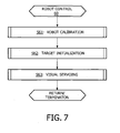
- FIG. 7 illustrates a flowchart 60 representative of a robot control method executed by robotic system 20 ( FIG. 1 ) on behalf of visual servo 51.
- flowchart 60 includes robot calibration stage S61 and a target initialization stage S62 as pre-requisites for a visual servoing stage S63.
- stage S61 upon an initial implementation of stage S61, only stages S62 and S63 may need to be executed for new image features to be tracked as would be appreciated by those skilled in the art.
- Stage S61 encompasses a robot calibration of robot 40 as known in the art involving an establishment of a mathematical relation between a joint space of robot 40 and end-effector 42.
- Stage 62 encompasses a target initialization of a particular feature of an image within digital video frames 32 as known in the art.
- vertical motion (insertion) of camera 30 within a particular environment is a parameter settable by a user of system 20 and therefore is beyond automatic control by visual servo 51.
- automatic control of robot 40 by visual servo 51 may be performed in two (2) end-effector 42 degrees of freedom including a theta angle ⁇ and a phi angle ⁇ for defining a two-dimensional spherical cap for robot 40.
- This may involve an establishment of a virtual remote-center-of-rotation ("RCM") for robot 40 upon an insertion of camera 30 within the environment whereby the virtual RCM fixes movements of robot 40 around a specified pivot point that defines a spherical conic workspace for robot 40 (e.g., an insertion point of an endoscope through a small incision in a patient's body during a minimally invasive surgical procedure).
- RCM virtual remote-center-of-rotation
- the spherical conic workspace is transformed into a two-dimensional spherical cap based on the theta angle ⁇ and the phi ⁇ angle as would be appreciated by one skilled in the art.
- the RCM point relative to the endoscope may be defined by (1) a utilization of a marker arranged along a shaft of the endoscope at a fixed distance from a tip the endoscope; (2) a user specification via a computer program of a distance between the RCM point and a tip of the endoscope; (3) a positioning of the tip of the endoscope scope at the desired insertion point followed by setting of the insertion point as the RCM and an insertion of the endoscope to the desired depth; or (4) a utilization of a predetermined point in space relative to robot 40 and a positioning of robot 40 whereby the predetermined point coincides with the desired insertion point.
- RCM-based motion of robot 40 will be the typical mode of operation implemented by robot controller 50 for the visual servoing of stage S63 of flowchart 60.
- robot controller 50 may implement an initial positioning of camera 40 for the visual servoing of stage S63 that defines the spherical conic workspace for camera 40.
- stage S63 encompasses a visual servoing involving feature tracking process 53 and inverse kinematics process 57 as previously described herein in connection with the description of FIG. 2 , and involves an exemplary embodiment of direction process setting 55 as shown in FIGS. 8-16 .
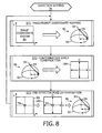
- FIG. 8 illustrates a flowchart 70 representative of a direction setting method of the present invention.
- end-effector 42 is represented by an endoscopic end-effector 93.
- endoscopic end-effector 93 is an endoscope having a proximal end coupled to robot 40 by any means known in the art.
- stage S71 of flowchart 70 encompasses a mapping of a two-dimensional image coordinate system 80 of each digital video frame 32 to a three-dimensional, two degrees-of-freedom robot coordinate system 90 of robot 40.
- image coordinate system 80 has an x axis and a y axis
- robot coordinate system 90 is a spherical cap having an axis symbolized by a dashed line extending from a pivot point 91 (e.g., a virtual RCM) to a two-dimensional plane 92 outlined by a full rotation of a endoscopic end-effector 93 about pivot point 91.
- theta angle ⁇ explicitly quantifies the degree of rotation of the distal tip of endoscopic end-effector 93 about the axis of the spherical cap relative to an origin point along a periphery of plane 92
- the phi angle ⁇ explicitly quantifies the degree of separation between the distal tip of endoscopic end-effector 93 from the axis of the spherical cap.
- theta angle ⁇ implicitly indicates the degree of rotation of the distal tip of endoscopic end-effector 93 about the axis of the spherical cap relative to an origin point along a periphery of plane 92
- the phi angle ⁇ implicitly indicates the degree of separation between the distal tip of endoscopic end-effector 93 from the axis of the spherical cap.
- a stage S72 of flowchart 70 encompasses a construction of a two-dimensional configuration space 100 of robot coordinate system 90 with respect to the possible ranges of the theta angle ⁇ and the phi angle ⁇ as defined by robot coordinate system 90.
- the configuration space construction involves a spherical projection of plane 92 of robot coordinate system 90 into a two-dimensional plane serving as configuration space 100.
- the resulting configuration space 100 represents a full configuration space of a tip of endoscopic end-effector 93 with respect to two settable parameters.
- a stage S73 of flowchart 70 encompasses a pose determination of endoscopic end-effector 93 relative robotic coordinate system 90 involving a mapping of a robot vector in configuration space 100 based on a mapping of a tracking vector in image coordinate system 80. Specifically, motion of an image within the image coordinate system 80 over multiple digital video frames is mapped within configuration space 100. This mapping is qualitative with an unknown scale in view of the fact that a position in pixels (implicitly millimeters) within image coordinate system 80 is transferred to pose of endoscopic end-effector 93 in two angles (radians) within robotic coordinate system 90 as represented by configuration space 100.
- an identification of a tracking vector (vtrk) of a minimum magnitude as represented by the circle around the tracking point (white X) enables a mapping of the tracking vector (vtrk) as a robot vector (vrob) within configuration space 100. While the mapping scale is unknown, the position of the target point TG within image coordinate system 80 is transformed to a pose of endoscopic end-effector 93 in two angles (radians) within robotic coordinate system 90 as represented by configuration space 100.
- the tracking direction of tracking vector (vtrk) within image coordinate system 80 dictates a robotic direction of robot vector (vrob) within robotic coordinate system 90, which in turn is processed via inverse kinematics to move robotic joint(s) 41 to achieve the pose of endoscopic end-effector 93 within robotic coordinate system 90.
- an identification of a tracking vector (vtrk) of a minimum magnitude enables a mapping of the tracking vector (vtrk) as a robot vector (vrob) within configuration space 100.
- the mapping scale is unknown, the position of the target point TG within image coordinate system 80 is transformed into a pose of endoscopic end-effector 93 in two angles (radians) within robotic coordinate system 90 as represented by configuration space 100.
- the tracking direction of tracking vector (vtrk) within image coordinate system 80 dictates a robotic direction of robot vector (vrob) within robotic coordinate system 90, which in turn is processed via inverse kinematics to move the joint(s) 41 of robot 40 to achieve the pose of endoscopic end-effector 93 within robotic coordinate system 90.
- tracking vector (vtrk) is normalized (i.e., length set to one) and transferred as robot vector (vrob) to configuration space 100.
- the values of the theta angle ⁇ and the phi angle ⁇ associated with robot vector (vrob) therefore define a unit robot displacement in a given direction of robot vector (vrob).
- robot 40 may be velocity-controlled whereby the unit robot displacement is defined in radians/second in both the theta angle ⁇ and the phi angle ⁇ directions.
- robot vector (vrob) Since robot vector (vrob) is normalized, velocities in the theta angle ⁇ and the phi angle ⁇ directions should be ⁇ 1 radian/second. However, depending on other parameters (e.g.; depth of feature in digital video frames 32, relative speed of the tracking point in digital video frames 32, etc.), the velocity of robot vector (vrob) may be insufficient for tracking point TR to reach target point TG, or may be too fast whereby tracking point TR overshoots the target point TG.
- other parameters e.g.; depth of feature in digital video frames 32, relative speed of the tracking point in digital video frames 32, etc.
- FIG. 15 illustrates a flowchart 110 and FIG. 16 illustrates a flowchart 120 with both being representative of an optimal visual servoing method that may be implemented during stage S73 to optimize the tracking speed component of a tracking vector.
- stage S111 of flowchart 110 involves an initialization of a speed factor (s) and an identification of a tracking vector (vtrk) in image coordinate system 80 whenever the target point has been displaced from the tracking point between two (2) successive sampling frames of digital video frames 32.
- the initial value of speed factor (s) may be any dimensionless empirical value (e.g., ⁇ 1 ⁇ ).
- Stage S111 further involves an initialization of a reference vector (vref) equaling tracking vector (vtrk).
- a stage S112 of flowchart 110 involves an identification of a robot vector (vrob) within configuration workspace 100 that involves a mapping of tracking vector (vtrk) within configuration workspace 100.
- Stage S 112 further involves setting a tracking velocity as a product of speed factor (s) and robot vector (vrob) whereby speed factor (s) adjusts the radians/second value of the theta angle ⁇ and the phi angle ⁇ associated with robot vector (vrob).
- Tracking velocity (s*vrob) is mapped to robot coordinate space 100 to thereby use the corresponding theta angle ⁇ and phi ⁇ angle to generate 3D robot data as an indication of the robot movement needed for implementing tracking velocity (s*vrob).
- any displacement between the tracking point and the target point must be updated from subsequent frames of digital video frames 32 in view of the facts that (1) the target point may be moving in image coordinate system 80 of successive sampling digital image frames 32 due to any movement of end-effector 42 and (2) the target point may be moving in a coordinate system of the environment.
- Stages S113-S117 of flowchart 110 are therefore utilized to adjust the tracking velocity at the sampling rate of digital video frames 32 (e.g., every frame of digital video frames 32 or at a specified frame-rate of digital video frames 32).
- stage S 113 involves an updating of tracking vector (vtrk) between the tracking point and the target point in a successive sampling frame of digital video frames 32.
- Stage S114 determines whether tracking vector (vtrk) is less than an accuracy threshold that is established to maintain a stable positioning of robot 40 in the presence of insignificant noise within the successive sampling frame of digital video frames 32. If tracking vector (vtrk) is less than the accuracy threshold, then flowchart 110 returns to stage S113 to update tracking vector (vtrk) within the next successive sampling frame of digital video frames 32. Otherwise, flowchart 110 proceeds to stage S 115 to determine if an angle between tracking vector (vtrk) and reference vector (vref) is less than an angular threshold X° (e.g., 90°).
- an angle between tracking vector (vtrk) and reference vector (vref) is less than an angular threshold X° (e.g., 90°).
- flowchart 110 proceeds to stage S116 to update reference vector (vref) equal to the tracking vector (vtrk) and to increment speed factor (s), and thereafter returns to stage S112 to repeat the loop as needed for additional sampling frames of digital video frames 32. If the angle between tracking vector (vtrk) and reference vector (vref) is equal to or greater than the angular threshold X°, then flowchart 110 proceeds to stage S 117 to update reference vector (vref) equal to the tracking vector (vtrk) and to decrement speed factor (s), and thereafter returns to stage S112 to repeat the loop as needed for additional sampling frames of digital video frames 32.
- tracking vector (vtrk) and reference vector (vref) may change orientation if the user of system 20 rotates camera 30 (e.g., a rotation of an endoscope around its shaft or a rotation of a CCD camera at the proximal end of the endoscope). If that kind of motion is not allowed by the system, then stage S 117 may be omitted.
- stage S115 evaluates an angular displacement between a newly updated tracking vector (S113) and a previously updated reference vector (vref) to determine if the newly updated tracking vector (vtrk) is in the same general direction as the previously updated reference vector (vref) (e.g., angle (vtrk, vref) ⁇ 90°) or if the newly updated tracking vector (vtrk) is pointing in a different direction as the previously updated reference vector (vref) (e.g., angle (e.g., (vtrk,vref) ⁇ 90°).
- the change of direction may be accomplished at any angle larger than 0° and smaller than 90 °.
- robot 40 is assumed to be moving in the correct direction for moving the tracking point in a direction of the target point in digital video frames 32 without having overshot the target point.
- the reference vector (vref) is updated and speed factor (s) is increased during stage S116 and the tracking of the target point continues during another loop of stages S112-S117.
- an initial tracking vector (vtrk) is identified within a first frame of image coordinate system 80(1) and utilized to map robot vector (vrob) in configuration workspace 100(1). Tracking velocity (s*vrob) is set for robot vector (vrob) whereby robot 40 is moved accordingly and tracking vector (vtrk) is updated within a second frame of image coordinate system 80(2) as shown in FIG.
- Tracking vector (vtrk) of FIG. 10 is in the same general direction as tracking vector (vtrk) shown in FIG. 9 .
- reference vector (vref) is updated as tracking vector (vtrk) shown in image coordinate system 80(1) and speed factor (s) is increased.
- the updated tracking vector (vtrk) within the second frame of image coordinate system 80(2) is utilized to map robot vector (vrob) in configuration workspace 100(2).
- Tracking velocity (s*vrob) is then updated for robot vector (vrob) whereby robot 40 is moved accordingly and a new tracking vector (vtrk) is identified within a third frame of image coordinate system 80(3) as shown in FIG. 11 .
- Tracking vector (vtrk) (not shown in FIG. 11 ) is less than the accuracy threshold of stage S 114 as symbolized by the circle surrounding the tracking point and robot 40 is set in a fixed position until the next updated tracking vector (vtrk) is equal to or greater than the accuracy threshold.
- robot 40 is assumed to be moving in the correct direction for moving the tracking point in a direction of the target point in digital video frames 32 but overshoots the target point, or the target point has changed directions in a successive sampling frame of digital video frames 32.
- reference vector (vref) is updated and speed factor (s) is decreased during stage S116 and the tracking of the target point continues during another loop of stages S112-S117.
- an initial tracking vector (vtrk) identified within a fourth frame of image coordinate system 80(4) is utilized to map robot vector (vrob) in configuration workspace 100(4).
- Tracking velocity (s*vrob) is generated for robot vector (vrob) whereby robot 40 is moved accordingly and a new tracking vector (vtrk) is identified within a fifth frame of image coordinate system 80(5) as shown in FIG. 13 .
- Tracking vector (vtrk) of FIG. 13 is in a different direction as compared to the direction of the tracking vector (vtrk) shown in FIG. 12 .
- reference vector (vref) is updated as tracking vector (vtrk) of image coordinate system 80(4) and speed factor (s) is decreased.
- the updated tracking vector (vtrk) within the fifth frame of image coordinate system 80(5) is utilized to map robot vector (vrob) in configuration workspace 100(5).
- Tracking velocity (s*vrob) is then updated for robot vector (vrob) whereby robot 40 is moved accordingly and a new tracking vector (vtrk) is identified within a sixth frame of image coordinate system 80(6) as shown in FIG. 14 .
- Tracking vector (vtrk) (not shown in FIG. 14 ) is less than the accuracy threshold of stage S114 as symbolized by the circle surrounding the tracking point and robot 40 is set in a fixed position until the next tracking vector (vtrk) is equal to or greater than the accuracy threshold.
- flowchart 120 is synonymous with flowchart 110 ( FIG. 14 ) with the exception of an implementation of proportional control using a length factor (1) of the tracking vector in the image coordinate system 80.
- Length factor (1) is indicative of how far the tracking point is from the target point and may be expressed in pixels.
- length factor (1) is initialized accordingly during stage S121 of flowchart 120, and tracking velocity of robot vector (vrob) may be expressed as (s*1*vrob) in stage S 122 of flowchart 120.
- the dimension of the speed factor (s) is mm/(s*pixel).
- a proportional control of length factor (1) during stages S126 and S127 may enhanced with derivative and integral factors of the length factor (1), similar as in PID (proportional-integral-derivative) control known in art.
- FIGS. 9-14 illustrate two simple examples of an optimization of speed factor (s).
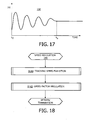
- an advantage of stages S112-S117 ( FIG. 15 ) and stages S122-S127 ( FIG. 16 ) is that visual servo 51 is learning an optimal speed factor (s) in real time. If the target point is moving with a constant velocity, an initial variation of speed factor (s) will stabilize after multiple frames of digital video frames 32 as shown in FIG. 17 with the stabilization of speed factor (s) after a time t s covering the frames. Otherwise, if the tracking point is moving with a varying velocity, an initial variation of speed factor (s) will stabilize after multiple frames of digital video frames 32 with some amount of noise.
- FIG. 18 illustrates a flowchart 140 representative of a speed regulation method of the present invention.
- a stage S 141 of flowchart 140 encompasses an evaluation of the speed of the tracking velocity (s*rob) or (s*1*rob) in view of a tracking latency of the tracking point or in view of the application of system 20.
- the control of robot 40 is attempting to track the tracking point at its maximum speed of robot 40 possible at any given time.
- the stabilization of speed factor (s) and the tracking latency are evaluated for purposes of regulating speed factor (s) during a stage S 142 of flowchart 140 in an attempt to track the tracking point at its maximum speed possible at any given time.
- the increment value and the decrement value of speed factor (s) is decreased during stage S 142 for a stable speed factor (s) having a low tracking latency or for an unstable speed factor (s) (e.g., target point overshoot tracking point).
- the increment value and the decrement value of speed factor (s) are increased during stage S 142 of flowchart 140 for a stable speed factor (s) having a high tracking latency.
- parameters affecting the tracking latency other than inherent robot speed includes, but is not limited to, distance between the tracking point and the target point, an insertion depth of camera 30, a distance between a tip of camera 30 and a RCM insertion point. Nonetheless, regulation of speed factor (s) maintains an optimization of tracking velocity (s*rob) or (s*1*vrob) despite any changes in the parameters.
- the control of robot 40 is not attempting to track the tracking point within digital video frames 32 at a maximum speed of robot 40, but at a speed appropriate for the application.
- a speed range of tracking velocity (s*rob) or (s*1*vrob) is evaluated in view of a predicted motion of the tracking point determined by visual servo 51 from digital video frames 32 or supplied to visual servo 51 by an operator of system 20.
- Speed factor (s) is set accordingly during stage S 142. For example, a static tracking of a surgical tool would ignore small tremors and speed factor (s) therefore would be set for ignoring small tremors. Also by example, a dynamic tracking of a beating heart involves fast changes in motion of the heart and speed factor (s) therefore would be set to follow the fast changes in the motion of the heart.
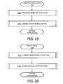
- FIG. 19 illustrates a flowchart 150 representative of a direction evaluation of the present invention for correcting a potential oscillation of robot 40 around the target point.
- a stage S151 of flowchart 150 encompasses an evaluation of a tracking direction of tracking velocity (s*rob) or (s*1*vrob) involving a counting of a number of consecutive directions changes between two given frames of digital video frames 32.
- flowchart 150 Upon the counter reaching a specified number of consecutive direction changes (preferably 2 or 3 consecutive direction changes), flowchart 150 proceeds to stage S 152 to rotate the robot vector (vrob) as mapped in the configuration workspace 100 relative to tracking vector (vtrk) as mapped in the image coordinate system 80 prior to moving robot 40.
- the fastest technique for reaching convergence is to divide the configuration workspace into four (4) quadrants for rotation of 90°, 180° or 270°.
- Flowchart 150 is implemented during stage S112 whereby, upon detecting the correct quadrant, further divisions of the quadrant may be needed as the tracking direction is further evaluated.
- robot 40 may be controlled to automatically find and track a particular feature within digital video frames 32 once an insertion point (e.g., a RCM point) has been defined for an oblique optical viewing camera 30.
- FIG. 20 illustrates a flowchart 160 representative of a target probe method for the automatic finding and tracking of a particular feature within image 40.
- a stage S161 of flowchart 160 encompasses a camera sweep involving a rotation of camera 30 about is axis relative to the insertion point.
- robot controller 50 locks the configuration of the sweep during a stage S162 of flowchart 160 as the robot coordinate system 90 for purposes of direction setting as previously described herein.
Applications Claiming Priority (2)
| Application Number | Priority Date | Filing Date | Title |
|---|---|---|---|
| US29322210P | 2010-01-08 | 2010-01-08 | |
| PCT/IB2010/055245 WO2011083374A1 (en) | 2010-01-08 | 2010-11-17 | Uncalibrated visual servoing using real-time velocity optimization |
Publications (2)
| Publication Number | Publication Date |
|---|---|
| EP2521507A1 EP2521507A1 (en) | 2012-11-14 |
| EP2521507B1 true EP2521507B1 (en) | 2015-01-14 |
Family
ID=43498595
Family Applications (1)
| Application Number | Title | Priority Date | Filing Date |
|---|---|---|---|
| EP10793050.5A Active EP2521507B1 (en) | 2010-01-08 | 2010-11-17 | Uncalibrated visual servoing using real-time velocity optimization |
Country Status (5)
| Country | Link |
|---|---|
| US (2) | US8934003B2 (zh) |
| EP (1) | EP2521507B1 (zh) |
| JP (1) | JP5814938B2 (zh) |
| CN (1) | CN102791214B (zh) |
| WO (1) | WO2011083374A1 (zh) |
Families Citing this family (72)
| Publication number | Priority date | Publication date | Assignee | Title |
|---|---|---|---|---|
| US8923602B2 (en) * | 2008-07-22 | 2014-12-30 | Comau, Inc. | Automated guidance and recognition system and method of the same |
| GB201003883D0 (en) * | 2010-03-09 | 2010-04-21 | Univ Southampton | Apparatus and method for measurement of hand joint movement |
| EP2369899A1 (en) | 2010-03-25 | 2011-09-28 | Koninklijke Philips Electronics N.V. | Method for controlling an outdoor lighting system, a computer program product, a controlling device and an outdoor lighting system |
| WO2011123758A1 (en) * | 2010-04-03 | 2011-10-06 | Centeye, Inc. | Vision based hover in place |
| US10231787B2 (en) * | 2012-01-12 | 2019-03-19 | Brainlab Ag | Method and system for medical tracking using a plurality of camera positions |
| WO2013132501A1 (en) * | 2012-03-07 | 2013-09-12 | M.S.T. Medical Surgery Technologies Ltd. | Overall endoscopic control system |
| US9616573B2 (en) * | 2012-05-25 | 2017-04-11 | The Ritsumeikan Trust | Robot control apparatus, robot control method, program, recording medium and robot system |
| JP5766150B2 (ja) * | 2012-05-29 | 2015-08-19 | 国立大学法人東京工業大学 | 内視鏡操作システム |
| RU2686954C2 (ru) | 2012-06-28 | 2019-05-06 | Конинклейке Филипс Н.В. | Навигация с помощью оптоволоконного датчика для визуализации и мониторинга сосудов |
| US9220570B2 (en) | 2012-06-29 | 2015-12-29 | Children's National Medical Center | Automated surgical and interventional procedures |
| CN104298244B (zh) * | 2013-07-17 | 2016-12-28 | 刘永 | 一种工业机器人三维实时高精度定位装置的定位方法 |
| US9295372B2 (en) * | 2013-09-18 | 2016-03-29 | Cerner Innovation, Inc. | Marking and tracking an area of interest during endoscopy |
| CN103544701B (zh) * | 2013-10-15 | 2016-03-02 | 中国科学院自动化研究所 | 一种多路显微视觉标定系统及方法 |
| JP6000928B2 (ja) * | 2013-10-24 | 2016-10-05 | オリンパス株式会社 | 医療用マニピュレータおよび医療用マニピュレータの初期化方法 |
| CN105934216B (zh) * | 2014-01-24 | 2019-09-17 | 皇家飞利浦有限公司 | 机器人引导系统、控制单元和装置 |
| EP3104804B1 (en) | 2014-02-12 | 2021-12-15 | Koninklijke Philips N.V. | Robotic control of surgical instrument visibility |
| JP6364836B2 (ja) * | 2014-03-14 | 2018-08-01 | セイコーエプソン株式会社 | ロボット、ロボットシステム、及び制御装置 |
| US9841749B2 (en) | 2014-04-01 | 2017-12-12 | Bot & Dolly, Llc | Runtime controller for robotic manufacturing system |
| US9701018B2 (en) | 2014-04-01 | 2017-07-11 | Bot & Dolly, Llc | Software interface for authoring robotic manufacturing process |
| US9278449B1 (en) | 2014-05-21 | 2016-03-08 | Bot & Dolly, Llc | Closed-loop control system for robotic operation |
| US9555545B2 (en) | 2014-05-21 | 2017-01-31 | Bot & Dolly, Llc | Systems and methods for time-based parallel robotic operation |
| US9308647B2 (en) * | 2014-06-03 | 2016-04-12 | Bot & Dolly, Llc | Systems and methods for instructing robotic operation |
| CN106572887B (zh) * | 2014-07-15 | 2020-05-12 | 皇家飞利浦有限公司 | X射线套件中的图像整合和机器人内窥镜控制 |
| DE102014226240A1 (de) * | 2014-12-17 | 2016-06-23 | Kuka Roboter Gmbh | System zur roboterunterstützten medizinischen Behandlung |
| JP6433389B2 (ja) * | 2015-08-04 | 2018-12-05 | キヤノン株式会社 | 画像処理装置、画像処理方法およびプログラム |
| JP6871929B2 (ja) * | 2015-09-29 | 2021-05-19 | コーニンクレッカ フィリップス エヌ ヴェKoninklijke Philips N.V. | ロボット支援低侵襲手術のための器具コントローラ |
| US10893913B2 (en) * | 2015-12-10 | 2021-01-19 | Covidien Lp | Robotic surgical systems with independent roll, pitch, and yaw scaling |
| US11209954B2 (en) | 2015-12-10 | 2021-12-28 | Cmr Surgical Limited | Surgical robotic system using dynamically generated icons to represent orientations of instruments |
| WO2017114834A1 (en) * | 2015-12-29 | 2017-07-06 | Koninklijke Philips N.V. | System, controller and method using virtual reality device for robotic surgery |
| US10786319B2 (en) * | 2015-12-29 | 2020-09-29 | Koninklijke Philips N.V. | System, control unit and method for control of a surgical robot |
| EP3397187A1 (en) | 2015-12-30 | 2018-11-07 | Koninklijke Philips N.V. | Image based robot guidance |
| US11399901B2 (en) | 2016-03-31 | 2022-08-02 | Koninklijke Philips N.V. | Image guided robotic system for tumor aspiration |
| CN105643607A (zh) * | 2016-04-08 | 2016-06-08 | 深圳市中科智敏机器人科技有限公司 | 一种具备感知和认知能力的智能工业机器人 |
| CN106256310B (zh) * | 2016-08-18 | 2018-04-13 | 中国科学院深圳先进技术研究院 | 自动调节鼻内镜位姿的方法和系统 |
| CN106239520A (zh) * | 2016-08-23 | 2016-12-21 | 深圳市中科智敏机器人科技有限公司 | 具备认知能力的智能工业机器人运动控制系统 |
| CN110678141A (zh) * | 2017-03-31 | 2020-01-10 | 皇家飞利浦有限公司 | 无标记机器人跟踪系统、控制器和方法 |
| EP3648674A1 (en) | 2017-07-07 | 2020-05-13 | Koninklijke Philips N.V. | Robotic instrument guide integration with an acoustic probe |
| US11406255B2 (en) | 2018-01-03 | 2022-08-09 | Koninklijke Philips N.V. | System and method for detecting abnormal tissue using vascular features |
| US11833696B2 (en) | 2018-01-15 | 2023-12-05 | Technische Universität München | Vision-based sensor system and control method for robot arms |
| CN110051436B (zh) * | 2018-01-18 | 2020-04-17 | 上海舍成医疗器械有限公司 | 自动化协同工作组件及其在手术器械中的应用 |
| EP3781363B1 (en) * | 2018-04-17 | 2023-06-07 | ABB Schweiz AG | Method for controlling a robot arm |
| US20200015904A1 (en) | 2018-07-16 | 2020-01-16 | Ethicon Llc | Surgical visualization controls |
| JP7325173B2 (ja) * | 2018-10-06 | 2023-08-14 | シスメックス株式会社 | 手術支援ロボットの遠隔支援方法、および遠隔支援システム |
| CN109454639A (zh) * | 2018-11-02 | 2019-03-12 | 广东人励智能工程有限公司 | 一种智能制造生产线中机器人臂调整的方法及系统 |
| US10926416B2 (en) * | 2018-11-21 | 2021-02-23 | Ford Global Technologies, Llc | Robotic manipulation using an independently actuated vision system, an adversarial control scheme, and a multi-tasking deep learning architecture |
| US20200205911A1 (en) * | 2019-01-01 | 2020-07-02 | Transenterix Surgical, Inc. | Determining Relative Robot Base Positions Using Computer Vision |
| JP6898374B2 (ja) * | 2019-03-25 | 2021-07-07 | ファナック株式会社 | ロボット装置の動作を調整する動作調整装置およびロボット装置の動作を調整する動作調整方法 |
| CN110039542B (zh) * | 2019-06-13 | 2022-04-12 | 东北大学 | 具有速度方向控制的视觉伺服跟踪控制方法及机器人系统 |
| IT201900009354A1 (it) | 2019-06-18 | 2020-12-18 | Hiro Robotics S R L | Robot con controllo di inseguimento pezzo e metodo di controllo di un end effector corrispondentemente ad un pezzo da trattare spostabile nello spazio |
| GB2585691B (en) * | 2019-07-11 | 2024-03-20 | Cmr Surgical Ltd | Anonymising robotic data |
| US11173610B2 (en) | 2019-11-13 | 2021-11-16 | Vicarious Fpc, Inc. | Method and system for robot control using visual feedback |
| CN111179308B (zh) * | 2019-12-17 | 2022-10-11 | 清华大学 | 一种基于视觉伺服的果蝇跟踪方法及系统 |
| US11832996B2 (en) | 2019-12-30 | 2023-12-05 | Cilag Gmbh International | Analyzing surgical trends by a surgical system |
| US20210196384A1 (en) * | 2019-12-30 | 2021-07-01 | Ethicon Llc | Dynamic surgical visualization systems |
| US11896442B2 (en) | 2019-12-30 | 2024-02-13 | Cilag Gmbh International | Surgical systems for proposing and corroborating organ portion removals |
| US11219501B2 (en) | 2019-12-30 | 2022-01-11 | Cilag Gmbh International | Visualization systems using structured light |
| US11776144B2 (en) | 2019-12-30 | 2023-10-03 | Cilag Gmbh International | System and method for determining, adjusting, and managing resection margin about a subject tissue |
| US11759283B2 (en) | 2019-12-30 | 2023-09-19 | Cilag Gmbh International | Surgical systems for generating three dimensional constructs of anatomical organs and coupling identified anatomical structures thereto |
| US11284963B2 (en) | 2019-12-30 | 2022-03-29 | Cilag Gmbh International | Method of using imaging devices in surgery |
| US11744667B2 (en) | 2019-12-30 | 2023-09-05 | Cilag Gmbh International | Adaptive visualization by a surgical system |
| US11648060B2 (en) | 2019-12-30 | 2023-05-16 | Cilag Gmbh International | Surgical system for overlaying surgical instrument data onto a virtual three dimensional construct of an organ |
| US11409091B2 (en) * | 2019-12-31 | 2022-08-09 | Carl Zeiss Meditec Ag | Method of operating a surgical microscope and surgical microscope |
| US11607287B2 (en) * | 2019-12-31 | 2023-03-21 | Carl Zeiss Meditec Ag | Method of operating a surgical microscope and surgical microscope |
| US11864841B2 (en) | 2019-12-31 | 2024-01-09 | Carl Zeiss Meditec Ag | Method of operating a surgical microscope and surgical microscope |
| US20210244485A1 (en) * | 2020-02-12 | 2021-08-12 | Medtech S.A. | Robotic guided 3d structured light-based camera |
| US11969218B2 (en) | 2020-07-05 | 2024-04-30 | Asensus Surgical Us, Inc. | Augmented reality surgery set-up for robotic surgical procedures |
| USD1022197S1 (en) | 2020-11-19 | 2024-04-09 | Auris Health, Inc. | Endoscope |
| CN112947569B (zh) * | 2021-03-09 | 2022-08-12 | 中南大学 | 基于预设性能四旋翼无人机视觉伺服目标跟踪控制方法 |
| CN113601498B (zh) * | 2021-07-11 | 2024-02-02 | 西北工业大学 | 基于权重分配的机器人视觉伺服与人机交互混合操控方法 |
| CN113848908B (zh) * | 2021-09-27 | 2024-04-05 | 浙江工业大学 | 一种全方位移动机器人视觉伺服系统的建模与控制方法 |
| CN113814986B (zh) * | 2021-11-23 | 2022-04-26 | 广东隆崎机器人有限公司 | 一种基于机器视觉控制scara机器人的方法及系统 |
| CN115082518B (zh) * | 2022-05-30 | 2024-03-26 | 华南理工大学 | 视觉伺服的在线轨迹生成系统及其方法 |
Family Cites Families (13)
| Publication number | Priority date | Publication date | Assignee | Title |
|---|---|---|---|---|
| JP3236070B2 (ja) * | 1992-06-04 | 2001-12-04 | オリンパス光学工業株式会社 | スコープ保持装置およびスコープ装置 |
| US5762458A (en) * | 1996-02-20 | 1998-06-09 | Computer Motion, Inc. | Method and apparatus for performing minimally invasive cardiac procedures |
| US5855583A (en) * | 1996-02-20 | 1999-01-05 | Computer Motion, Inc. | Method and apparatus for performing minimally invasive cardiac procedures |
| JP2000042960A (ja) * | 1998-07-29 | 2000-02-15 | Gifu Prefecture | マニピュレータの遠隔操作装置 |
| US6278906B1 (en) | 1999-01-29 | 2001-08-21 | Georgia Tech Research Corporation | Uncalibrated dynamic mechanical system controller |
| JP2006289531A (ja) | 2005-04-07 | 2006-10-26 | Seiko Epson Corp | ロボット位置教示のための移動制御装置、ロボットの位置教示装置、ロボット位置教示のための移動制御方法、ロボットの位置教示方法及びロボット位置教示のための移動制御プログラム |
| EP1769769A1 (en) * | 2005-09-28 | 2007-04-04 | DePuy Orthopädie GmbH | Tracking surgical items |
| US7819859B2 (en) * | 2005-12-20 | 2010-10-26 | Intuitive Surgical Operations, Inc. | Control system for reducing internally generated frictional and inertial resistance to manual positioning of a surgical manipulator |
| ES2298051B2 (es) | 2006-07-28 | 2009-03-16 | Universidad De Malaga | Sistema robotico de asistencia a la cirugia minimamente invasiva capaz de posicionar un instrumento quirurgico en respueta a las ordenes de un cirujano sin fijacion a la mesa de operaciones ni calibracion previa del punto de insercion. |
| WO2008113957A1 (fr) * | 2007-02-23 | 2008-09-25 | UNIVERSITE DE STRASBOURG (Etablissement Public à Caractère Scientifique, Culturel et Professionnel) | Dispositif d'endoscope flexible a asservissement visuel et procede de stabilisation d'un tel dispositif |
| WO2009045827A2 (en) * | 2007-09-30 | 2009-04-09 | Intuitive Surgical, Inc. | Methods and systems for tool locating and tool tracking robotic instruments in robotic surgical systems |
| KR20110097140A (ko) * | 2010-02-24 | 2011-08-31 | 삼성전자주식회사 | 이동 로봇의 위치 추정 장치 및 방법 |
| US9411037B2 (en) * | 2010-08-18 | 2016-08-09 | RetailNext, Inc. | Calibration of Wi-Fi localization from video localization |
-
2010
- 2010-11-17 WO PCT/IB2010/055245 patent/WO2011083374A1/en active Application Filing
- 2010-11-17 EP EP10793050.5A patent/EP2521507B1/en active Active
- 2010-11-17 CN CN201080065226.XA patent/CN102791214B/zh active Active
- 2010-11-17 US US13/519,383 patent/US8934003B2/en active Active
- 2010-11-17 JP JP2012547558A patent/JP5814938B2/ja active Active
-
2014
- 2014-12-18 US US14/574,637 patent/US9205564B2/en active Active
Also Published As
| Publication number | Publication date |
|---|---|
| US20150094856A1 (en) | 2015-04-02 |
| JP5814938B2 (ja) | 2015-11-17 |
| CN102791214A (zh) | 2012-11-21 |
| CN102791214B (zh) | 2016-01-20 |
| EP2521507A1 (en) | 2012-11-14 |
| WO2011083374A1 (en) | 2011-07-14 |
| JP2013516264A (ja) | 2013-05-13 |
| US20120307027A1 (en) | 2012-12-06 |
| US9205564B2 (en) | 2015-12-08 |
| US8934003B2 (en) | 2015-01-13 |
Similar Documents
| Publication | Publication Date | Title |
|---|---|---|
| EP2521507B1 (en) | Uncalibrated visual servoing using real-time velocity optimization | |
| JP2013516264A5 (zh) | ||
| US10675105B2 (en) | Controller definition of a robotic remote center of motion | |
| US11963666B2 (en) | Overall endoscopic control system | |
| US10945796B2 (en) | Robotic control of surgical instrument visibility | |
| JP7229319B2 (ja) | 手術支援装置、その制御方法、プログラム並びに手術支援システム | |
| US10786319B2 (en) | System, control unit and method for control of a surgical robot | |
| CN113180828B (zh) | 基于旋量理论的手术机器人约束运动控制方法 | |
| US20200261155A1 (en) | Image based robot guidance | |
| US20190069955A1 (en) | Control unit, system and method for controlling hybrid robot having rigid proximal portion and flexible distal portion | |
| WO2022054428A1 (ja) | 医療システムおよび制御方法 | |
| Popovic et al. | An approach to robotic guidance of an uncalibrated endoscope in beating heart surgery | |
| WO2015110929A1 (en) | Robotic control of an endoscope orientation |
Legal Events
| Date | Code | Title | Description |
|---|---|---|---|
| PUAI | Public reference made under article 153(3) epc to a published international application that has entered the european phase |
Free format text: ORIGINAL CODE: 0009012 |
|
| 17P | Request for examination filed |
Effective date: 20120808 |
|
| AK | Designated contracting states |
Kind code of ref document: A1 Designated state(s): AL AT BE BG CH CY CZ DE DK EE ES FI FR GB GR HR HU IE IS IT LI LT LU LV MC MK MT NL NO PL PT RO RS SE SI SK SM TR |
|
| DAX | Request for extension of the european patent (deleted) | ||
| RAP1 | Party data changed (applicant data changed or rights of an application transferred) |
Owner name: KONINKLIJKE PHILIPS N.V. |
|
| GRAP | Despatch of communication of intention to grant a patent |
Free format text: ORIGINAL CODE: EPIDOSNIGR1 |
|
| INTG | Intention to grant announced |
Effective date: 20140801 |
|
| GRAS | Grant fee paid |
Free format text: ORIGINAL CODE: EPIDOSNIGR3 |
|
| GRAA | (expected) grant |
Free format text: ORIGINAL CODE: 0009210 |
|
| AK | Designated contracting states |
Kind code of ref document: B1 Designated state(s): AL AT BE BG CH CY CZ DE DK EE ES FI FR GB GR HR HU IE IS IT LI LT LU LV MC MK MT NL NO PL PT RO RS SE SI SK SM TR |
|
| REG | Reference to a national code |
Ref country code: GB Ref legal event code: FG4D |
|
| REG | Reference to a national code |
Ref country code: CH Ref legal event code: EP |
|
| REG | Reference to a national code |
Ref country code: IE Ref legal event code: FG4D |
|
| REG | Reference to a national code |
Ref country code: AT Ref legal event code: REF Ref document number: 706586 Country of ref document: AT Kind code of ref document: T Effective date: 20150215 |
|
| REG | Reference to a national code |
Ref country code: DE Ref legal event code: R096 Ref document number: 602010021855 Country of ref document: DE Effective date: 20150226 |
|
| REG | Reference to a national code |
Ref country code: NL Ref legal event code: VDEP Effective date: 20150114 |
|
| REG | Reference to a national code |
Ref country code: AT Ref legal event code: MK05 Ref document number: 706586 Country of ref document: AT Kind code of ref document: T Effective date: 20150114 |
|
| REG | Reference to a national code |
Ref country code: LT Ref legal event code: MG4D |
|
| PG25 | Lapsed in a contracting state [announced via postgrant information from national office to epo] |
Ref country code: NO Free format text: LAPSE BECAUSE OF FAILURE TO SUBMIT A TRANSLATION OF THE DESCRIPTION OR TO PAY THE FEE WITHIN THE PRESCRIBED TIME-LIMIT Effective date: 20150414 Ref country code: SE Free format text: LAPSE BECAUSE OF FAILURE TO SUBMIT A TRANSLATION OF THE DESCRIPTION OR TO PAY THE FEE WITHIN THE PRESCRIBED TIME-LIMIT Effective date: 20150114 Ref country code: BG Free format text: LAPSE BECAUSE OF FAILURE TO SUBMIT A TRANSLATION OF THE DESCRIPTION OR TO PAY THE FEE WITHIN THE PRESCRIBED TIME-LIMIT Effective date: 20150414 Ref country code: HR Free format text: LAPSE BECAUSE OF FAILURE TO SUBMIT A TRANSLATION OF THE DESCRIPTION OR TO PAY THE FEE WITHIN THE PRESCRIBED TIME-LIMIT Effective date: 20150114 Ref country code: FI Free format text: LAPSE BECAUSE OF FAILURE TO SUBMIT A TRANSLATION OF THE DESCRIPTION OR TO PAY THE FEE WITHIN THE PRESCRIBED TIME-LIMIT Effective date: 20150114 Ref country code: ES Free format text: LAPSE BECAUSE OF FAILURE TO SUBMIT A TRANSLATION OF THE DESCRIPTION OR TO PAY THE FEE WITHIN THE PRESCRIBED TIME-LIMIT Effective date: 20150114 Ref country code: LT Free format text: LAPSE BECAUSE OF FAILURE TO SUBMIT A TRANSLATION OF THE DESCRIPTION OR TO PAY THE FEE WITHIN THE PRESCRIBED TIME-LIMIT Effective date: 20150114 |
|
| PG25 | Lapsed in a contracting state [announced via postgrant information from national office to epo] |
Ref country code: PL Free format text: LAPSE BECAUSE OF FAILURE TO SUBMIT A TRANSLATION OF THE DESCRIPTION OR TO PAY THE FEE WITHIN THE PRESCRIBED TIME-LIMIT Effective date: 20150114 Ref country code: GR Free format text: LAPSE BECAUSE OF FAILURE TO SUBMIT A TRANSLATION OF THE DESCRIPTION OR TO PAY THE FEE WITHIN THE PRESCRIBED TIME-LIMIT Effective date: 20150415 Ref country code: LV Free format text: LAPSE BECAUSE OF FAILURE TO SUBMIT A TRANSLATION OF THE DESCRIPTION OR TO PAY THE FEE WITHIN THE PRESCRIBED TIME-LIMIT Effective date: 20150114 Ref country code: AT Free format text: LAPSE BECAUSE OF FAILURE TO SUBMIT A TRANSLATION OF THE DESCRIPTION OR TO PAY THE FEE WITHIN THE PRESCRIBED TIME-LIMIT Effective date: 20150114 Ref country code: NL Free format text: LAPSE BECAUSE OF FAILURE TO SUBMIT A TRANSLATION OF THE DESCRIPTION OR TO PAY THE FEE WITHIN THE PRESCRIBED TIME-LIMIT Effective date: 20150114 Ref country code: RS Free format text: LAPSE BECAUSE OF FAILURE TO SUBMIT A TRANSLATION OF THE DESCRIPTION OR TO PAY THE FEE WITHIN THE PRESCRIBED TIME-LIMIT Effective date: 20150114 Ref country code: IS Free format text: LAPSE BECAUSE OF FAILURE TO SUBMIT A TRANSLATION OF THE DESCRIPTION OR TO PAY THE FEE WITHIN THE PRESCRIBED TIME-LIMIT Effective date: 20150514 |
|
| REG | Reference to a national code |
Ref country code: DE Ref legal event code: R097 Ref document number: 602010021855 Country of ref document: DE |
|
| PG25 | Lapsed in a contracting state [announced via postgrant information from national office to epo] |
Ref country code: DK Free format text: LAPSE BECAUSE OF FAILURE TO SUBMIT A TRANSLATION OF THE DESCRIPTION OR TO PAY THE FEE WITHIN THE PRESCRIBED TIME-LIMIT Effective date: 20150114 Ref country code: CZ Free format text: LAPSE BECAUSE OF FAILURE TO SUBMIT A TRANSLATION OF THE DESCRIPTION OR TO PAY THE FEE WITHIN THE PRESCRIBED TIME-LIMIT Effective date: 20150114 Ref country code: RO Free format text: LAPSE BECAUSE OF FAILURE TO SUBMIT A TRANSLATION OF THE DESCRIPTION OR TO PAY THE FEE WITHIN THE PRESCRIBED TIME-LIMIT Effective date: 20150114 Ref country code: EE Free format text: LAPSE BECAUSE OF FAILURE TO SUBMIT A TRANSLATION OF THE DESCRIPTION OR TO PAY THE FEE WITHIN THE PRESCRIBED TIME-LIMIT Effective date: 20150114 Ref country code: SK Free format text: LAPSE BECAUSE OF FAILURE TO SUBMIT A TRANSLATION OF THE DESCRIPTION OR TO PAY THE FEE WITHIN THE PRESCRIBED TIME-LIMIT Effective date: 20150114 |
|
| PLBE | No opposition filed within time limit |
Free format text: ORIGINAL CODE: 0009261 |
|
| STAA | Information on the status of an ep patent application or granted ep patent |
Free format text: STATUS: NO OPPOSITION FILED WITHIN TIME LIMIT |
|
| 26N | No opposition filed |
Effective date: 20151015 |
|
| PG25 | Lapsed in a contracting state [announced via postgrant information from national office to epo] |
Ref country code: IT Free format text: LAPSE BECAUSE OF FAILURE TO SUBMIT A TRANSLATION OF THE DESCRIPTION OR TO PAY THE FEE WITHIN THE PRESCRIBED TIME-LIMIT Effective date: 20150114 |
|
| PG25 | Lapsed in a contracting state [announced via postgrant information from national office to epo] |
Ref country code: SI Free format text: LAPSE BECAUSE OF FAILURE TO SUBMIT A TRANSLATION OF THE DESCRIPTION OR TO PAY THE FEE WITHIN THE PRESCRIBED TIME-LIMIT Effective date: 20150114 |
|
| PG25 | Lapsed in a contracting state [announced via postgrant information from national office to epo] |
Ref country code: BE Free format text: LAPSE BECAUSE OF FAILURE TO SUBMIT A TRANSLATION OF THE DESCRIPTION OR TO PAY THE FEE WITHIN THE PRESCRIBED TIME-LIMIT Effective date: 20150114 |
|
| PG25 | Lapsed in a contracting state [announced via postgrant information from national office to epo] |
Ref country code: LU Free format text: LAPSE BECAUSE OF FAILURE TO SUBMIT A TRANSLATION OF THE DESCRIPTION OR TO PAY THE FEE WITHIN THE PRESCRIBED TIME-LIMIT Effective date: 20151117 Ref country code: MC Free format text: LAPSE BECAUSE OF FAILURE TO SUBMIT A TRANSLATION OF THE DESCRIPTION OR TO PAY THE FEE WITHIN THE PRESCRIBED TIME-LIMIT Effective date: 20150114 |
|
| REG | Reference to a national code |
Ref country code: CH Ref legal event code: PL |
|
| PG25 | Lapsed in a contracting state [announced via postgrant information from national office to epo] |
Ref country code: CH Free format text: LAPSE BECAUSE OF NON-PAYMENT OF DUE FEES Effective date: 20151130 Ref country code: LI Free format text: LAPSE BECAUSE OF NON-PAYMENT OF DUE FEES Effective date: 20151130 |
|
| REG | Reference to a national code |
Ref country code: IE Ref legal event code: MM4A |
|
| REG | Reference to a national code |
Ref country code: FR Ref legal event code: ST Effective date: 20160729 |
|
| PG25 | Lapsed in a contracting state [announced via postgrant information from national office to epo] |
Ref country code: IE Free format text: LAPSE BECAUSE OF NON-PAYMENT OF DUE FEES Effective date: 20151117 |
|
| PG25 | Lapsed in a contracting state [announced via postgrant information from national office to epo] |
Ref country code: FR Free format text: LAPSE BECAUSE OF NON-PAYMENT OF DUE FEES Effective date: 20151130 |
|
| PG25 | Lapsed in a contracting state [announced via postgrant information from national office to epo] |
Ref country code: HU Free format text: LAPSE BECAUSE OF FAILURE TO SUBMIT A TRANSLATION OF THE DESCRIPTION OR TO PAY THE FEE WITHIN THE PRESCRIBED TIME-LIMIT; INVALID AB INITIO Effective date: 20101117 Ref country code: SM Free format text: LAPSE BECAUSE OF FAILURE TO SUBMIT A TRANSLATION OF THE DESCRIPTION OR TO PAY THE FEE WITHIN THE PRESCRIBED TIME-LIMIT Effective date: 20150114 |
|
| PG25 | Lapsed in a contracting state [announced via postgrant information from national office to epo] |
Ref country code: CY Free format text: LAPSE BECAUSE OF FAILURE TO SUBMIT A TRANSLATION OF THE DESCRIPTION OR TO PAY THE FEE WITHIN THE PRESCRIBED TIME-LIMIT Effective date: 20150114 |
|
| PG25 | Lapsed in a contracting state [announced via postgrant information from national office to epo] |
Ref country code: MT Free format text: LAPSE BECAUSE OF FAILURE TO SUBMIT A TRANSLATION OF THE DESCRIPTION OR TO PAY THE FEE WITHIN THE PRESCRIBED TIME-LIMIT Effective date: 20150114 |
|
| PG25 | Lapsed in a contracting state [announced via postgrant information from national office to epo] |
Ref country code: PT Free format text: LAPSE BECAUSE OF FAILURE TO SUBMIT A TRANSLATION OF THE DESCRIPTION OR TO PAY THE FEE WITHIN THE PRESCRIBED TIME-LIMIT Effective date: 20150114 Ref country code: MK Free format text: LAPSE BECAUSE OF FAILURE TO SUBMIT A TRANSLATION OF THE DESCRIPTION OR TO PAY THE FEE WITHIN THE PRESCRIBED TIME-LIMIT Effective date: 20150114 Ref country code: TR Free format text: LAPSE BECAUSE OF FAILURE TO SUBMIT A TRANSLATION OF THE DESCRIPTION OR TO PAY THE FEE WITHIN THE PRESCRIBED TIME-LIMIT Effective date: 20150114 |
|
| PG25 | Lapsed in a contracting state [announced via postgrant information from national office to epo] |
Ref country code: AL Free format text: LAPSE BECAUSE OF FAILURE TO SUBMIT A TRANSLATION OF THE DESCRIPTION OR TO PAY THE FEE WITHIN THE PRESCRIBED TIME-LIMIT Effective date: 20150114 |
|
| PGFP | Annual fee paid to national office [announced via postgrant information from national office to epo] |
Ref country code: GB Payment date: 20231121 Year of fee payment: 14 |
|
| PGFP | Annual fee paid to national office [announced via postgrant information from national office to epo] |
Ref country code: DE Payment date: 20231127 Year of fee payment: 14 |