EP2520810A2 - Vorrichtung mit einer Leitstruktur - Google Patents
Vorrichtung mit einer Leitstruktur Download PDFInfo
- Publication number
- EP2520810A2 EP2520810A2 EP12002240A EP12002240A EP2520810A2 EP 2520810 A2 EP2520810 A2 EP 2520810A2 EP 12002240 A EP12002240 A EP 12002240A EP 12002240 A EP12002240 A EP 12002240A EP 2520810 A2 EP2520810 A2 EP 2520810A2
- Authority
- EP
- European Patent Office
- Prior art keywords
- flange
- guide structure
- vacuum pump
- high vacuum
- pump
- Prior art date
- Legal status (The legal status is an assumption and is not a legal conclusion. Google has not performed a legal analysis and makes no representation as to the accuracy of the status listed.)
- Granted
Links
Images


Classifications
-
- F—MECHANICAL ENGINEERING; LIGHTING; HEATING; WEAPONS; BLASTING
- F04—POSITIVE - DISPLACEMENT MACHINES FOR LIQUIDS; PUMPS FOR LIQUIDS OR ELASTIC FLUIDS
- F04D—NON-POSITIVE-DISPLACEMENT PUMPS
- F04D29/00—Details, component parts, or accessories
- F04D29/70—Suction grids; Strainers; Dust separation; Cleaning
- F04D29/701—Suction grids; Strainers; Dust separation; Cleaning especially adapted for elastic fluid pumps
-
- B—PERFORMING OPERATIONS; TRANSPORTING
- B01—PHYSICAL OR CHEMICAL PROCESSES OR APPARATUS IN GENERAL
- B01D—SEPARATION
- B01D45/00—Separating dispersed particles from gases or vapours by gravity, inertia, or centrifugal forces
- B01D45/04—Separating dispersed particles from gases or vapours by gravity, inertia, or centrifugal forces by utilising inertia
- B01D45/08—Separating dispersed particles from gases or vapours by gravity, inertia, or centrifugal forces by utilising inertia by impingement against baffle separators
-
- B—PERFORMING OPERATIONS; TRANSPORTING
- B01—PHYSICAL OR CHEMICAL PROCESSES OR APPARATUS IN GENERAL
- B01D—SEPARATION
- B01D53/00—Separation of gases or vapours; Recovering vapours of volatile solvents from gases; Chemical or biological purification of waste gases, e.g. engine exhaust gases, smoke, fumes, flue gases, aerosols
- B01D53/24—Separation of gases or vapours; Recovering vapours of volatile solvents from gases; Chemical or biological purification of waste gases, e.g. engine exhaust gases, smoke, fumes, flue gases, aerosols by centrifugal force
-
- F—MECHANICAL ENGINEERING; LIGHTING; HEATING; WEAPONS; BLASTING
- F04—POSITIVE - DISPLACEMENT MACHINES FOR LIQUIDS; PUMPS FOR LIQUIDS OR ELASTIC FLUIDS
- F04D—NON-POSITIVE-DISPLACEMENT PUMPS
- F04D19/00—Axial-flow pumps
- F04D19/02—Multi-stage pumps
- F04D19/04—Multi-stage pumps specially adapted to the production of a high vacuum, e.g. molecular pumps
- F04D19/042—Turbomolecular vacuum pumps
-
- F—MECHANICAL ENGINEERING; LIGHTING; HEATING; WEAPONS; BLASTING
- F04—POSITIVE - DISPLACEMENT MACHINES FOR LIQUIDS; PUMPS FOR LIQUIDS OR ELASTIC FLUIDS
- F04D—NON-POSITIVE-DISPLACEMENT PUMPS
- F04D29/00—Details, component parts, or accessories
- F04D29/70—Suction grids; Strainers; Dust separation; Cleaning
Definitions
- the invention relates to a device according to the preamble of claim 1.
- High vacuum pumps are indispensable in the process industry.
- the generation of vacuum by means of turbomolecular pumps in semiconductor production may be mentioned.
- the gases to be pumped often contain components that can condense to form layers. It is important to reduce the penetration of such components in the turbomolecular pump, because precipitation on the rapidly rotating rotor lead to an increasing imbalance. This in turn can lead to premature failure of the pump.
- baffles are provided, which should reduce deposits in the high vacuum pump to a tolerable level.
- the advantage of the claimed device is that the number of critical gas molecules that make it up to the high vacuum pump is significantly reduced by performing at least two impacts with a wall.
- the impact with a wall surface of the device increases the likelihood of condensation of critical molecules, such as metallic vapors or non-metals such as selenium and sulfur, in the device.
- Danger for the high vacuum pump is averted so that the deposited molecules in the Voutter can no longer deposit in the high vacuum pump. This results in an optimal protection of the high vacuum pump with low losses of pumping through the limited conductance of the device.
- claims 2 and 3 bring additional benefits in terms of maintenance.
- the material is deposited on an accessible part of the device, which facilitates cleaning.
- cleaning is facilitated with a maintenance flange according to claims 6 and 7.
- the features of claims 4 and 5 provide the additional advantage that the deposition rate on cooled surfaces is higher, which in combination with the number of wall joints enhances deposition and thus protection the high vacuum pump is increased.
- the feature of claim 8 allows a structurally simple and inexpensive construction, since a T-piece with three pipe sections can be used.
- the high vacuum pump and chamber are not on a line of sight.
- the guide structure comprises guide plates according to claim 9.
- the device cooperates with such high-vacuum pumps, which have a rapidly rotating rotor, in particular by turbomolecular design, since Deposits on this impact particularly seriously.
- Fast rotation here means a few tens of thousands of revolutions per minute.
- FIG. 1 an arrangement with a high vacuum pump 2, a chamber 10 and a device 30.
- the chamber has an interior 12 in which run processes, such as the production of solar cells.
- the interior may contain corresponding internals or be connected to the interiors of other chambers in which the internals are included.
- the processes create vapors and gases, which are extracted by the high vacuum pump together with the atmosphere.
- a chamber flange 18 is provided, which is mounted in the example shown on a pipe section 16. In some applications, however, this pipe section is dispensed with, in other cases, other components such as gate valves and the like are provided.
- the high vacuum pump is designed as a turbomolecular pump and has a rotor turbomolekularer type 4.
- the pumped gas is passed from her to a not shown, arranged downstream in the gas flow pump, which compresses to atmospheric pressure.
- the high-vacuum pump has a pump flange 6.
- a device 30 In the gas flow between the high vacuum pump and the chamber is a device 30. It has a first flange 32 which is detachably connected to the chamber flange, and passes through the gas into the device. A second flange 34 is provided which is releasably connected to the pump flange of the vacuum pump.
- a guide structure 50 In the housing of the device is a guide structure 50. This is arranged and designed so that each passing directly from the interior 12 of the chamber through the first flange molecule on the way between the first and second flange performs at least two shocks with the device.
- Fig. 1 Trajectory sections of two molecules are given as an example. On the first trajectory 112 moves a molecule which passes directly from the interior of the first flange and until then no impact, for example with the pipe section 16, has performed. On the second trajectory 114 this leads Molecule first a shock with the inner wall of the pipe section through, before it passes through the first flange.
- the lead structure is designed so that the molecule can fly from the inner wall of the pipe section only along the line shown through the guide structure. On every other trajectory it hits the device.
- the allowable trajectory is sized to make a second impact with the device.
- the lead structure may be arranged and configured such that each molecule passing through the first flange performs at least two impacts with the device on the path between the first and second flanges. This means a further increase in the probability of condensation within the device. It also simplifies the design, since only geometric sizes of the device must be considered.
- the guide structure may be connected to a cooling circuit comprising a coolant inlet 40, a coolant tube 42 and a coolant outlet 44.
- a cooling circuit comprising a coolant inlet 40, a coolant tube 42 and a coolant outlet 44.
- Part of the cooled portion of the device may be an inner body 52 that substantially covers the inner walls of the device.
- Inner body and guide structure can be removed for cleaning or replacement by a maintenance flange 36 closed by a cover 38.
- Coolant inlet and coolant outlet can be arranged on the lid.
- Fig. 2 is the section marked by a dashed circle Fig. 1 shown in more detail.
- the lead structure includes baffles divided into three legs 80, 82 and 84.
- the baffles are arranged offset from one another so that angled channels 86 are formed between the legs of the baffles. Of the Offset is chosen so that the line of sight 106 is just blocked so a molecule therefore can not pass through the lead structure without bumping with the guide structure.
- the in Fig. 1 note the condition shown. This is that the line of sight intersects on the one hand a wall between the interior and the guide structure and on the other hand a wall between the device and the rotor. Because chambers and high vacuum pumps are not standardized, it is advantageous for usability in any equipment to alter the condition such that the line of sight intersects a wall of the device on both sides of the conductive structure.
- a slightly different embodiment of the lead structure shows Fig. 3 ,
- 32 angle plates 54 are provided with apprisschenkligem cross-section in front of the second flange.
- the leg lengths, the angle between the legs and the distance of the angle plates to each other are chosen so that the guide structure is optically dense, so there is no direct line of sight connection between both sides of the guide structure.
- Apertures 56 may be used for some sections of the lead structure.
- a molecule passes through the first flange 34 in a first flight phase 116 and strikes an inner wall of the inner body 52 at point A. After a short dwell time, the second flight phase 118 begins, at the end of which it grabs the guide structure 50. Due to their optical tightness, the molecule can not without shock of Coming point A coming through the guide structure to the second flange 32.
- baffles are divided into two levels.
- a first set of baffle 58 is provided within the device in the gas flow past the first flange 32.
- the baffles have a single-sided cross-section, whereby a straight channel 88 is formed.
- a second set of baffles 60 is provided, between which straight channels 90 are formed.
- Length, angle of inclination and distance of the baffles of each baffle set and angle between the straight channels 88 and 90 are sized as follows.
- As a first condition it is satisfied that there is no way for a molecule to fly through both channels 88 and 90 without impact with one of the baffles.
- the abovementioned parameters of the conductive structure are now chosen such that it is satisfied as a second condition that no molecule starting from the impact zone 110 can exit the second flange 34 without impact with the second baffle set.
- Fig. 5 is presented as an opportunity to design the interaction of a baffle and a level with baffles.
- the baffles 64 are arranged so that only such molecules can reach an impingement zone 110 provided in the gas flow behind the guide structure, which start from a baffle 62 arranged in the gas flow between the first flange 32 and the guide structure.
- Baffle and Conductor structure are also designed and arranged so that no molecule can fly directly or with a shock through the first and second flange 34. Each molecule passing through the conductive structure without impact will make at least two impacts with the device, one with the baffle wall and one with the landing zone on the inner body 52.
- the device 30 according to Fig. 6 has a substantially tubular housing.
- a power structure 50 is provided which comprises a plurality of annular and concentrically arranged sheets.
- the cross-section of the sheets is multi-legged, wherein the interconnected legs 66 and 68 are at a first and a second angle to each other.
- the legs and angles are designed so that a molecule that moves along a first trajectory 112 parallel to the longitudinal axis 108 of the tube can not move directly through the guide structure but must perform with this two shocks. This takes place after the in Fig. 2 described principle.
- the guide structure may be attached to a cover 38, with which together they can be removed from the device, for example for maintenance.
- the lead structure 50 includes apertures.
- the diaphragms 70 and 72 are advantageously rotationally symmetrical.
- Aperture 70 may be a circular disk or a cone, the tip of which is oriented in the direction of the first flange 32 and whose base points in the direction of aperture 72. This can be designed as a pinhole.
- the diameter of the circular disc, the aperture in the aperture and the distance between the diaphragms are as follows: a Molecule can not pass directly or by impact through the lead structure. In addition, only molecules that have previously been impacted by the device and that have landed on a part of the device after the passage must pass through the guide structure.
Landscapes
- Engineering & Computer Science (AREA)
- Chemical & Material Sciences (AREA)
- Mechanical Engineering (AREA)
- General Engineering & Computer Science (AREA)
- Chemical Kinetics & Catalysis (AREA)
- Analytical Chemistry (AREA)
- General Chemical & Material Sciences (AREA)
- Oil, Petroleum & Natural Gas (AREA)
- Non-Positive Displacement Air Blowers (AREA)
Abstract
Description
- Die Erfindung betrifft eine Vorrichtung nach dem Oberbegriff des Anspruchs 1.
- Hochvakuumpumpen sind aus der Prozessindustrie nicht wegzudenken. Beispielhaft sei die Erzeugung von Vakuum mittels Turbomolekularpumpen in der Halbleiterherstellung genannt. Die abzupumpenden Gase enthalten häufig Bestandteile, die zu Schichten auskondensieren können. Es gilt, das Eindringen solcher Bestandteile in die Turbomolekularpumpe zu reduzieren, denn Niederschläge auf dem sich schnell drehenden Rotor führen zu einer anwachsenden Unwucht. Diese wiederum kann zu einem vorzeitigen Ausfall der Pumpe führen.
- Zum Schutz von Hochvakuumpumpen sind Vorrichtungen bekannt, die im Gasstrom vor dem Einlass der Hochvakuumpumpe angeordnet sind. Im Gehäuse der Vorrichtung sind Leitbleche vorgesehen, die Abscheidungen in der Hochvakuumpumpe auf ein tolerierbares Maß reduzieren sollen.
- Bei der Gestaltung solcher Schutzeinrichtungen sind sich widersprechende Anforderungen zu erfüllen: einerseits sollen möglichst viele kritische Gase aus dem Gasstrom entfernt werden. Andererseits darf das Saugvermögen der Hochvakuumpumpe nicht zu stark gesenkt werden, da sonst erhebliche Mehrkosten entstehen.
- Es ist daher Aufgabe der Erfindung, eine Vorrichtung vorzustellen, die die Bildung von Ablagerungen in der Hochvakuumpumpe reduziert.
- Diese Aufgabe wird gelöst durch eine Vorrichtung mit den Merkmalen des ersten Anspruchs. Die abhängigen Ansprüche 2 bis 10 geben vorteilhafte Weiterbildungen an.
- Der Vorteil der beanspruchten Vorrichtung ist, dass die Zahl der Moleküle kritischer Gase, die es bis zur Hochvakuumpumpe schaffen, durch das Ausführen von mindestens zwei Stößen mit einer Wand deutlich reduziert wird. Der Stoß mit einer Wandfläche der Vorrichtung führt erhöht die Wahrscheinlichkeit der Kondensation kritischer Moleküle, beispielsweise metallischer Dämpfe oder Nichtmetalle wie Selen und Schwefel, in der Vorrichtung. Gefahr für die Hochvakuumpumpe wird so abgewendet, da sich die in der Vorichtung abgelagerten Moleküle nicht mehr in der Hochvakuumpumpe ablagern können. Es ergibt sich auf diese Weise ein optimaler Schutz der Hochvakuumpumpe bei geringen Einbußen an Saugvermögen durch den begrenzten Leitwert der Vorrichtung.
- Die Merkmale der Ansprüche 2 und 3 bringen zusätzliche Vorteile im Hinblick auf die Wartung. Durch Ablagerung auf der Leitstruktur wird das Material auf einem zugänglichen Teil der Vorrichtung abgeschieden, was die Reinigung erleichtert. Zusätzlich erleicht wird die Reinigung mit einem Wartungsflansch nach Anspruch 6 und 7. Die Merkmale der Ansprüche 4 und 5 bringen den zusätzlichen Vorteil, dass die Abscheidungsrate auf gekühlten Flächen höher ist, wodurch im Zusammenwirken mit der Zahl der Wandstöße die Abscheidung verstärkt und so der Schutz der Hochvakuumpumpe erhöht wird. Das Merkmal nach Anspruch 8 erlaubt einen konstruktiv einfachen und kostengünstigen Aufbau, da ein T-Stück mit drei Rohrabschnitten zum Einsatz kommen kann. Außerdem befinden sich durch die winklige Anordnung von erstem und zweitem Flansch Hochvakuumpumpe und Kammer nicht auf einer Sichtlinie. Dies vereinfacht die Gestaltung der Leitstruktur, da die Symmetrie der Anordnung reduziert ist und ein notwendiger Stoß während der Passage des Winkels ausgenutzt werden kann. Es ist kostengünstig, wenn die Leitstruktur Leitbleche nach Anspruch 9 umfasst. Besonders vorteilhaft wirkt die Vorrichtung mit solchen Hochvakuumpumpen zusammen, die einen sich schnell drehenden Rotor, insbesondere nach turbomolekularer Bauart, aufweisen, da sich Ablagerungen auf diesem besonders gravierend auswirken. Schnelle Drehung bedeutet hier einige Zigtausend Umdrehungen pro Minute.
- An Hand eines Ausführungsbeispiels und seiner Weiterbildungen sollen die Darstellung der Erfindung vertieft und die Vorteile herausgearbeitet werden. Es zeigen:
- Fig. 1:
- Teilschnitt durch eine Anordnung mit einem Rezipienten, einer Vorrichtung und einer Hochvakuumpumpe;
- Fig. 2:
- Darstellung des Wirkprinzips der Leitstruktur aus
Fig.1 ; - Fig. 3:
- Schematische Darstellung einer winkligen Anordnung von Rezipient und Hochvakuumpumpe mit einer Vorrichtung, die eine chevronförmige Leitstruktur an einem Flansch aufweist;
- Fig. 4:
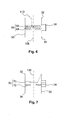
- Schematische Darstellung einer winkligen Anordnung von Rezipient und Hochvakuumpumpe mit einer Vorrichtung, die eine Leitstruktur mit in zwei Ebenen angeordneten Leitbleche aufweist;
- Fig. 5:
- Schematische Darstellung einer winkligen Anordnung von Rezipient und Hochvakuumpumpe mit einer Vorrichtung, die eine Leitstruktur mit Kanalabschnitten aufweist, die nur von Vorrichtungswand zugänglich sind und auf eine solche führen;
- Fig. 6:
- Schematische Darstellung einer geraden Anordnung von Rezipient, Vorrichtung und Hochvakuumpumpe, wobei die Leitstruktur Leitbleche in einer doppelten Chevronanordnung umfasst;
- Fig. 7:
- Schematische Darstellung einer geraden Anordnung von Rezipient, Vorrichtung und Hochvakuumpumpe, wobei die Leitstruktur rotationssymmetrische Blenden umfasst.
- In einem Teilschnitt zeigt
Fig. 1 eine Anordnung mit einer Hochvakuumpumpe 2, einer Kammer 10 und einer Vorrichtung 30. Die Kammer besitzt einen Innenraum 12, in welchem Prozesse ablaufen, beispielsweise die Herstellung von Solarzellen. - Der Innenraum kann entsprechende Einbauten enthalten oder mit den Innenräumen weiterer Kammern verbunden sein, in denen die Einbauten enthalten sind. Durch die Prozesse entstehen Dämpfe und Gase, die zusammen mit der Atmosphäre von der Hochvakuumpumpe abgesaugt werden. Um die Absaugung zur ermöglichen, ist ein Kammerflansch 18 vorgesehen, der im gezeigten Beispiel an einem Rohrstück 16 angebracht ist. In einigen Anwendungen wird jedoch auf dieses Rohrstück verzichtet, in anderen wiederum sind weitere Bauteile wie Sperrschieber und dergleichen vorgesehen.
- Die Hochvakuumpumpe ist als Turbomolekularpumpe ausgestaltet und weist einen Rotor turbomolekularer Bauart 4 auf. Das abgepumpte Gas wird von ihr an eine nicht dargestellte, im Gasstrom nachfolgend angeordnete Pumpe übergeben, die bis auf Atmosphärendruck verdichtet. Zur Kopplung an zu evakuierende Baugruppen weist die Hochvakuumpumpe einen Pumpenflansch 6 auf.
- Im Gasstrom zwischen Hochvakuumpumpe und Kammer befindet sich eine Vorrichtung 30. Sie weist einen ersten Flansch 32 auf, der mit dem Kammerflansch lösbar verbunden ist, und durch den Gas in die Vorrichtung gelangt. Ein zweiter Flansch 34 ist vorgesehen, der mit dem Pumpenflansch der Vakuumpumpe lösbar verbunden ist.
- Im Gehäuse der Vorrichtung befindet sich eine Leitstruktur 50. Diese ist so angeordnet und gestaltet, dass jedes direkt aus dem Innenraum 12 der Kammer durch den ersten Flansch hindurchtretende Molekül auf dem Weg zwischen erstem und zweitem Flansch wenigstens zwei Stöße mit der Vorrichtung ausführt. In
Fig. 1 sind Flugbahnabschnitte zweier Moleküle als Beispiel angegeben. Auf der ersten Trajektorie 112 bewegt sich ein Molekül, welches direkt aus dem Innenraum kommend den ersten Flansch durchtritt und bis dahin keinen Stoß, beispielsweise mit dem Rohrstück 16, durchgeführt hat. Auf der zweiten Trajektorie 114 führt das Molekül zunächst einen Stoß mit der Innenwand des Rohrstücks durch, bevor es durch den ersten Flansch hindurchtritt. Die Leitstruktur ist so gestaltet, dass das Molekül von der Innenwand des Rohrstücks nur entlang der gezeigten Linie durch die Leitstruktur hindurchfliegen kann. Bei jeder anderen Flugbahn stößt es mit der Vorrichtung. Die erlaubte Flugbahn ist so bemessen, dass es einen zweiten Stoß mit der Vorrichtung durchführt. - Die Leitstruktur kann so angeordnet und gestaltet sein, dass jedes durch den ersten Flansch hindurchtretende Molekül auf dem Weg zwischen erstem und zweitem Flansch wenigstens zwei Stöße mit der Vorrichtung ausführt. Dies bedeutet eine weitere Erhöhung der Kondensationswahrscheinlichkeit innerhalb der Vorrichtung. Es vereinfacht zudem die Konstruktion, da nur geometrische Größen der Vorrichtung beachtet werden müssen.
- Die Leitstruktur kann an einen Kühlungskreislauf angeschlossen sein, der einen Kühlmittelzulauf 40, ein Kühlmittelrohr 42 und einen Kühlmittelablauf 44 umfasst. Teil des gekühlten Bereichs der Vorrichtung kann ein Innenkörper 52 sein, der im Wesentlichen die Innenwandungen der Vorrichtung abdeckt. Innenkörper und Leitstruktur sind durch einen von einem Deckel 38 verschlossenen Wartungsflansch 36 heraus zur Reinigung oder zum Ersatz entnehmbar. Kühlmittelzulauf und Kühlmittelablauf können auf dem Deckel angeordnet sein.
- Die nachfolgenden Figuren dienen der Erläuterung des Wirkprinzips der Leitstruktur und zeigen Gestaltungswege auf.
- In
Fig. 2 ist der durch einen gestrichelten Kreis markierte Teilbereich ausFig. 1 detaillierter dargestellt. Die Leitstruktur umfasst Leitbleche, die in drei Schenkel 80, 82 und 84 aufgeteilt sind. Die Leitbleche sind so versetzt zueinander angeordnet, dass zwischen den Schenkeln der Leitbleche abgewinkelte Kanäle 86 entstehen. Der Versatz ist dabei so gewählt, dass die Sichtlinie 106 gerade so versperrt wird, ein Molekül daher nicht durch die Leitstruktur hindurchtreten kann, ohne mit der Leitstruktur zu stoßen. Sollte die Sichtlinie geöffnet werden, ist die inFig. 1 gezeigte Bedingung zu beachten. Diese lautet, dass die Sichtlinie einerseits eine Wand zwischen Innenraum und Leitstruktur und andererseits eine Wand zwischen Vorrichtung und Rotor schneidet. Da Kammern und Hochvakuumpumpen nicht genormt sind, ist es zur Verwendbarkeit in beliebigen Anlagen vorteilhaft, die Bedingung derart abzuändern, dass die Sichtlinie beidseits der Leitstruktur eine Wand der Vorrichtung schneidet. - Die Mehrheit aller Moleküle muss mehrere Stöße mit der Leitstruktur durchführen. Dies ist an dem Weg eines Moleküls gezeigt. Es kommt in einer ersten Flugphase 116 aus dem Innenraum der Kammer und trifft in Punkt A auf den Schenkel 80 eines Leitbleches. Von dort startet es, da die Vorrichtung im molekularen Strömungsbereich betrieben wird, gemäß der bekannten statistischen Kosinusverteilung. Nach einer Flugphase 118 berührt es den Schenkel 82 in Punkt B und startet von dort in die dritte Fugphase 120, mit der es die Leitstruktur verlässt.
- Eine etwas andere Ausgestaltung der Leitstruktur zeigt
Fig. 3 . Hier sind vor dem zweiten Flansch 32 Winkelbleche 54 mit zweischenkligem Querschnitt vorgesehen. Die Schenkellängen, der Winkel zwischen den Schenkeln und der Abstand der Winkelbleche zueinander sind so gewählt, dass die Leitstruktur optisch dicht ist, es also keine direkte Sichtlinienverbindung zwischen beiden Seiten der Leitstruktur gibt. Für einige Abschnitte der Leitstruktur können Blenden 56 zum Einsatz kommen. Ein Molekül tritt in einer ersten Flugphase 116 durch den ersten Flansch 34 und trifft an Punkt A auf eine innere Wand des Innenkörpers 52. Nach kurzer Verweilzeit beginnt die zweite Flugphase 118, an derem Ende er auf die Leitstruktur 50 trift. Durch deren optische Dichtheit kann das Molekül nicht ohne Stoß von Punkt A kommend durch die Leitstruktur hindurch zum zweiten Flansch 32 gelangen. - Mit der Leitstruktur nach
Fig. 4 wird eine weitere Gestaltungsmöglichkeit ausgeschöpft. Anstelle einer einzigen Ebene mit Leitblechen, sind hier die Leitbleche in zwei Ebenen aufgeteilt. Ein erster Satz Leitblech 58 ist innerhalb der Vorrichtung im Gasstrom hinter dem ersten Flansch 32 vorgesehen. Die Leitbleche weisen einen einschenkligen Querschnitt auf, wodurch ein gerader Kanal 88 entsteht. - Im Gasstrom vor dem zweiten Flansch 34 ist ein zweiter Satz Leitbleche 60 vorgesehen, zwischen denen gerade Kanäle 90 ausgebildet sind.
- Länge, Neigungswinkel und Abstand der Leitbleche eines jeden Leitblechsatzes und Winkel zwischen den geraden Kanälen 88 und 90 sind wie folgt bemessen. Als erste Bedingung ist erfüllt, dass es für ein Molekül keine Möglichkeit gibt, ohne Stoß mit einem der Leitbleche durch beide Kanäle 88 und 90 hindurchzufliegen. Ein Molekül, welches durch den ersten Flansch 32 hindurchtritt und nicht mit dem ersten Leitblechsatz stößt, kann gemäß der Trajektorien 112 und 114 nur in einer Auftreffzone 110 mit dem Innenkörper 52 stoßen. Die vorgenannten Parameter der Leitstruktur sind nun so gewählt, dass als zweite Bedingung erfüllt ist, dass kein aus der Auftreffzone 110 startendes Molekül ohne Stoß mit dem zweiten Leitblechsatz durch den zweiten Flansch 34 austreten kann.
- In
Fig. 5 ist als Gestaltungsmöglichkeit das Zusammenspiel einer Prallwand und einer Ebene mit Leitblechen vorgestellt. Die Leitbleche 64 sind so angeordnet, dass nur solche Moleküle eine im Gasstrom hinter der Leitstruktur vorgesehenen Auftreffzone 110 erreichen können, die von einer im Gasstrom zwischen erstem Flansch 32 und Leitstruktur angeordneten Prallwand 62 starten. Prallwand und Leitstruktur sind zudem so gestaltet und angeordnet, dass kein Molekül direkt oder mit einem Stoß durch ersten und zweiten Flansch 34 fliegen kann. Jedes ohne Stoß durch die Leitstruktur hindurchtretendes Molekül führt mindestens zwei Stöße mit der Vorrichtung aus, nämlich einen mit der Prallwand und einen mit der Auftreffzone auf dem Innenkörper 52. - Bisher wurden Vorrichtungen betrachtet, bei denen die Ebenen von erstem und zweitem Flansch einen Winkel miteinander bilden. Auch auf Vorrichtungen mit geradem Durchtritt, bei dem die Flanschebenen etwa parallel zueinander sind, ist der Erfindungsgedanke anwendbar. Dies ist in den
Fig. 6 und 7 dargestellt. - Die Vorrichtung 30 gemäß
Fig. 6 weist ein im Wesentlichen rohrförmiges Gehäuse auf. In diesem Gehäuse ist eine Leistruktur 50 vorgesehen, die mehrere ringförmige und konzentrisch zueinander angeordnete Bleche umfasst. Der Querschnitt der Bleche ist mehrschenklig, wobei die miteinander verbundenen Schenkel in einem ersten und einem zweiten Winkel 66 und 68 zueinander stehen. Die Schenkel und Winkel sind dabei so gestaltet, dass ein Molekül, das sich entlang einer ersten Trajektorie 112 parallel zur Längsachse 108 des Rohres bewegt, nicht auf direktem Weg durch die Leitstruktur hindurchbewegen kann sondern mit dieser zwei Stöße ausführen muss. Dies vollzieht sich nach dem inFig. 2 beschriebenen Prinzip. Die Leitstruktur kann einem Deckel 38 befestigt sein, mit dem zusammen sie von der Vorrichtung abmontiert werden kann, beispielsweise zur Wartung. - In der Vorrichtung gemäß
Fig. 7 umfasst die Leitstruktur 50 Blenden. Die Blenden 70 und 72 sind vorteilhaft rotationssymmetrisch aufgebaut. Blende 70 kann eine Kreisscheibe sind oder ein Kegel, dessen Spitze in Richtung erstem Flansch 32 orientiert ist und dessen Basis in Richtung Blende 72 zeigt. Diese kann als Lochblende gestaltet sein. Durchmesser der Kreisscheibe, der Öffnung in der Lochblende und Abstand der Blenden zueinander sind wie folgt bemessen: ein Molekül kann nicht auf direktem Wege oder mittels einem Stoß durch die Leitstruktur hindurchtreten. Zudem dürfen nur solche Moleküle durch die Leitstruktur gelangen, die zuvor einen Stoß mit der Vorrichtung durchgeführt haben und nach dem Durchtritt wieder auf einem Teil der Vorrichtung landen..
Claims (10)
- Vorrichtung (30) mit einer Leitstruktur (50) und einem Gehäuse, welches einen ersten Flansch (32) zum Verbinden der Vorrichtung mit einem einen Innenraum (12) besitzenden Rezipienten (10) und einen zweiten Flansch (6) zum Verbinden der Vorrichtung mit einer Hochvakuumpumpe (2) aufweist, dadurch gekennzeichnet, dass die Leitstruktur (50) so angeordnet und gestaltet ist, dass jedes direkt aus dem Innenraum durch den ersten Flansch hindurchtretende Molekül auf dem Weg zwischen erstem und zweitem Flansch wenigstens zwei Stöße mit der Vorrichtung (30) ausführt.
- Vorrichtung nach Anspruch 1, dadurch gekennzeichnet, dass die Leitstruktur (50) so angeordnet und gestaltet ist, dass ein Stoß mit der Leitstruktur stattfindet.
- Vorrichtung nach Anspruch 1, dadurch gekennzeichnet, dass die Leitstruktur (50) so angeordnet und gestaltet ist, dass wenigstens zwei Stöße mit der Leitstruktur stattfinden.
- Vorrichtung nach einem der vorhergehenden Ansprüche, dadurch gekennzeichnet, dass die Leitstruktur (50) mit einer Kühleinrichtung (40, 42, 44) verbunden ist.
- Vorrichtung nach einem der vorhergehenden Ansprüche, dadurch gekennzeichnet, dass sie einen Innenkörper (52) umfasst, welcher mit einer Kühleinrichtung (40, 42, 44) verbunden ist.
- Vorrichtung nach einem der vorhergehenden Ansprüche, dadurch gekennzeichnet, dass sie einen Wartungsflansch (36) umfasst, durch welchen die Leitstruktur (50) entnehmbar ist.
- Vorrichtung nach Anspruch 6, dadurch gekennzeichnet, dass Leitstruktur (50) und Innenkörper (52) durch den Wartungsflansch (36) entnehmbar sind.
- Vorrichtung nach einem der vorhergehenden Ansprüche, dadurch gekennzeichnet, dass eine Flanschebene (100) des ersten Flansches und eine Flanschebene (102) des zweiten Flansches in einem von Null verschiedenen Winkel (104), vorzugsweise einem rechten Winkel, zueinander angeordnet sind.
- Vorrichtung nach einem der vorhergehenden Ansprüche, dadurch gekennzeichnet, dass die Leitstruktur (50) wenigstens ein Leitblech (54, 58, 60, 62, 64, 66, 68, 70, 72) umfasst.
- Anordnung mit einer Vorrichtung nach einem der vorhergehenden Ansprüche, dadurch gekennzeichnet, dass die Hochvakuumpumpe (2) einen schnelldrehenden Rotor (4), insbesondere nach turbomolekularer Bauart, aufweist.
Applications Claiming Priority (1)
| Application Number | Priority Date | Filing Date | Title |
|---|---|---|---|
| DE102011100311A DE102011100311A1 (de) | 2011-05-03 | 2011-05-03 | Vorrichtung mit einer Leitstruktur |
Publications (3)
| Publication Number | Publication Date |
|---|---|
| EP2520810A2 true EP2520810A2 (de) | 2012-11-07 |
| EP2520810A3 EP2520810A3 (de) | 2017-08-02 |
| EP2520810B1 EP2520810B1 (de) | 2020-01-08 |
Family
ID=46000617
Family Applications (1)
| Application Number | Title | Priority Date | Filing Date |
|---|---|---|---|
| EP12002240.5A Active EP2520810B1 (de) | 2011-05-03 | 2012-03-28 | Vorrichtung mit einer Leitstruktur |
Country Status (2)
| Country | Link |
|---|---|
| EP (1) | EP2520810B1 (de) |
| DE (1) | DE102011100311A1 (de) |
Families Citing this family (1)
| Publication number | Priority date | Publication date | Assignee | Title |
|---|---|---|---|---|
| JP6021677B2 (ja) * | 2013-02-15 | 2016-11-09 | 株式会社神戸製鋼所 | プラズマcvd装置 |
Family Cites Families (7)
| Publication number | Priority date | Publication date | Assignee | Title |
|---|---|---|---|---|
| US5537833A (en) * | 1995-05-02 | 1996-07-23 | Helix Technology Corporation | Shielded cryogenic trap |
| US5974809A (en) * | 1998-01-21 | 1999-11-02 | Helix Technology Corporation | Cryopump with an exhaust filter |
| IT1302694B1 (it) * | 1998-10-19 | 2000-09-29 | Getters Spa | Dispositivo di schermatura mobile in funzione della temperatura trapompa getter e pompa turbomolecolare collegate in linea. |
| DE10317837A1 (de) * | 2003-04-16 | 2004-11-04 | Leybold Vakuum Gmbh | Vakuumkammer |
| JP5350598B2 (ja) * | 2007-03-28 | 2013-11-27 | 東京エレクトロン株式会社 | 排気ポンプ、連通管、排気システム及び基板処理装置 |
| DE202009006288U1 (de) * | 2009-04-28 | 2009-07-16 | Hsr Ag | Schutzvorrichtung für Hochvakuumpumpen, insbesondere Turbomolekularpumpen |
| EP2246573B1 (de) * | 2009-04-28 | 2013-02-13 | Hsr Ag | Schutzvorrichtung für Hochvakuumpumpen |
-
2011
- 2011-05-03 DE DE102011100311A patent/DE102011100311A1/de active Granted
-
2012
- 2012-03-28 EP EP12002240.5A patent/EP2520810B1/de active Active
Non-Patent Citations (1)
| Title |
|---|
| None |
Also Published As
| Publication number | Publication date |
|---|---|
| EP2520810B1 (de) | 2020-01-08 |
| DE102011100311A8 (de) | 2013-01-03 |
| EP2520810A3 (de) | 2017-08-02 |
| DE102011100311A1 (de) | 2012-11-08 |
Similar Documents
| Publication | Publication Date | Title |
|---|---|---|
| DE19940020C2 (de) | Extraktionseinrichtung | |
| DE956822C (de) | Turbinenschaufel fuer den Rotor einer Turbine | |
| EP2295812B1 (de) | Vakuumpumpe | |
| DE102009042857A1 (de) | Gasturbine mit Deckband-Labyrinthdichtung | |
| EP2025385A1 (de) | Abscheider | |
| DE102007044945A1 (de) | Vakuumpumpe | |
| EP2520810B1 (de) | Vorrichtung mit einer Leitstruktur | |
| DE102012213095A9 (de) | Gasseparation | |
| DE102008009715A1 (de) | Vakuumpump-System und Verwendung einer Mehrstufen-Vakuumpumpe | |
| EP3085963B1 (de) | Vakuumpumpe | |
| DE202015106402U1 (de) | Fluidgetriebener Antrieb und Aktuator | |
| DE69827887T2 (de) | Erosionsschutzschild in einer Luftströmung | |
| EP3180456B1 (de) | Verfahren und vorrichtung zur energieeinsparung und gleichzeitigen erhöhung der durchlaufgeschwindigkeit bei vakuum-beschichtungsanlagen | |
| DE377196C (de) | Vorrichtung zur Verhinderung von schaedlichen Gasstroemungen, welche das Ausscheiden von Unreinigkeiten mittels Zentrifugalkraft in schnell rotierenden Trommeln erschweren | |
| EP3486494B1 (de) | Radialgebläsegehäuse und radialgebläse | |
| WO2006136187A1 (de) | Vorrichtung für die sukzessive beschichtung mehrerer substrate | |
| DE102009033753A1 (de) | Verfahren und Anordnung zur Filmkühlung von Turbinenschaufeln | |
| DE202009006288U1 (de) | Schutzvorrichtung für Hochvakuumpumpen, insbesondere Turbomolekularpumpen | |
| EP3396171B1 (de) | Vakuumgerät mit wellendichtung | |
| EP2246573B1 (de) | Schutzvorrichtung für Hochvakuumpumpen | |
| DE102016116944B4 (de) | Vorrichtung zur Behandlung von Oberflächen von Kunststoffkörpern | |
| DE102013105477A1 (de) | Vorrichtung zur Minimierung der Festkörperpartikelerosion in Dampfturbinen | |
| DE102018222326A1 (de) | Kollektorspiegelanordnung für eine EUV-Lichtquelle | |
| EP3629366B1 (de) | Vakuumsystem und vakuumpumpe | |
| WO2005113157A1 (de) | Vorrichtung und verfahren zum aufteilen einer mittels einer gasströmung transportierten viskosen flüssigkeit in mindestens zwei teilströmen |
Legal Events
| Date | Code | Title | Description |
|---|---|---|---|
| PUAI | Public reference made under article 153(3) epc to a published international application that has entered the european phase |
Free format text: ORIGINAL CODE: 0009012 |
|
| AK | Designated contracting states |
Kind code of ref document: A2 Designated state(s): AL AT BE BG CH CY CZ DE DK EE ES FI FR GB GR HR HU IE IS IT LI LT LU LV MC MK MT NL NO PL PT RO RS SE SI SK SM TR |
|
| AX | Request for extension of the european patent |
Extension state: BA ME |
|
| PUAL | Search report despatched |
Free format text: ORIGINAL CODE: 0009013 |
|
| AK | Designated contracting states |
Kind code of ref document: A3 Designated state(s): AL AT BE BG CH CY CZ DE DK EE ES FI FR GB GR HR HU IE IS IT LI LT LU LV MC MK MT NL NO PL PT RO RS SE SI SK SM TR |
|
| AX | Request for extension of the european patent |
Extension state: BA ME |
|
| RIC1 | Information provided on ipc code assigned before grant |
Ipc: B01D 45/08 20060101ALI20170623BHEP Ipc: F04D 29/70 20060101AFI20170623BHEP Ipc: B01D 53/24 20060101ALI20170623BHEP |
|
| STAA | Information on the status of an ep patent application or granted ep patent |
Free format text: STATUS: REQUEST FOR EXAMINATION WAS MADE |
|
| 17P | Request for examination filed |
Effective date: 20171004 |
|
| RBV | Designated contracting states (corrected) |
Designated state(s): AL AT BE BG CH CY CZ DE DK EE ES FI FR GB GR HR HU IE IS IT LI LT LU LV MC MK MT NL NO PL PT RO RS SE SI SK SM TR |
|
| STAA | Information on the status of an ep patent application or granted ep patent |
Free format text: STATUS: EXAMINATION IS IN PROGRESS |
|
| 17Q | First examination report despatched |
Effective date: 20181122 |
|
| GRAP | Despatch of communication of intention to grant a patent |
Free format text: ORIGINAL CODE: EPIDOSNIGR1 |
|
| STAA | Information on the status of an ep patent application or granted ep patent |
Free format text: STATUS: GRANT OF PATENT IS INTENDED |
|
| RIN1 | Information on inventor provided before grant (corrected) |
Inventor name: NIESSNER, WOLFGANG Inventor name: HOFMANN, JAN |
|
| GRAJ | Information related to disapproval of communication of intention to grant by the applicant or resumption of examination proceedings by the epo deleted |
Free format text: ORIGINAL CODE: EPIDOSDIGR1 |
|
| STAA | Information on the status of an ep patent application or granted ep patent |
Free format text: STATUS: EXAMINATION IS IN PROGRESS |
|
| INTG | Intention to grant announced |
Effective date: 20190523 |
|
| GRAP | Despatch of communication of intention to grant a patent |
Free format text: ORIGINAL CODE: EPIDOSNIGR1 |
|
| STAA | Information on the status of an ep patent application or granted ep patent |
Free format text: STATUS: GRANT OF PATENT IS INTENDED |
|
| INTC | Intention to grant announced (deleted) | ||
| INTG | Intention to grant announced |
Effective date: 20190719 |
|
| GRAS | Grant fee paid |
Free format text: ORIGINAL CODE: EPIDOSNIGR3 |
|
| GRAA | (expected) grant |
Free format text: ORIGINAL CODE: 0009210 |
|
| STAA | Information on the status of an ep patent application or granted ep patent |
Free format text: STATUS: THE PATENT HAS BEEN GRANTED |
|
| AK | Designated contracting states |
Kind code of ref document: B1 Designated state(s): AL AT BE BG CH CY CZ DE DK EE ES FI FR GB GR HR HU IE IS IT LI LT LU LV MC MK MT NL NO PL PT RO RS SE SI SK SM TR |
|
| REG | Reference to a national code |
Ref country code: GB Ref legal event code: FG4D Free format text: NOT ENGLISH |
|
| REG | Reference to a national code |
Ref country code: CH Ref legal event code: EP |
|
| REG | Reference to a national code |
Ref country code: DE Ref legal event code: R096 Ref document number: 502012015680 Country of ref document: DE |
|
| REG | Reference to a national code |
Ref country code: IE Ref legal event code: FG4D Free format text: LANGUAGE OF EP DOCUMENT: GERMAN |
|
| REG | Reference to a national code |
Ref country code: AT Ref legal event code: REF Ref document number: 1223078 Country of ref document: AT Kind code of ref document: T Effective date: 20200215 |
|
| REG | Reference to a national code |
Ref country code: NL Ref legal event code: MP Effective date: 20200108 |
|
| REG | Reference to a national code |
Ref country code: LT Ref legal event code: MG4D |
|
| PG25 | Lapsed in a contracting state [announced via postgrant information from national office to epo] |
Ref country code: NO Free format text: LAPSE BECAUSE OF FAILURE TO SUBMIT A TRANSLATION OF THE DESCRIPTION OR TO PAY THE FEE WITHIN THE PRESCRIBED TIME-LIMIT Effective date: 20200408 Ref country code: FI Free format text: LAPSE BECAUSE OF FAILURE TO SUBMIT A TRANSLATION OF THE DESCRIPTION OR TO PAY THE FEE WITHIN THE PRESCRIBED TIME-LIMIT Effective date: 20200108 Ref country code: LT Free format text: LAPSE BECAUSE OF FAILURE TO SUBMIT A TRANSLATION OF THE DESCRIPTION OR TO PAY THE FEE WITHIN THE PRESCRIBED TIME-LIMIT Effective date: 20200108 Ref country code: RS Free format text: LAPSE BECAUSE OF FAILURE TO SUBMIT A TRANSLATION OF THE DESCRIPTION OR TO PAY THE FEE WITHIN THE PRESCRIBED TIME-LIMIT Effective date: 20200108 Ref country code: PT Free format text: LAPSE BECAUSE OF FAILURE TO SUBMIT A TRANSLATION OF THE DESCRIPTION OR TO PAY THE FEE WITHIN THE PRESCRIBED TIME-LIMIT Effective date: 20200531 Ref country code: NL Free format text: LAPSE BECAUSE OF FAILURE TO SUBMIT A TRANSLATION OF THE DESCRIPTION OR TO PAY THE FEE WITHIN THE PRESCRIBED TIME-LIMIT Effective date: 20200108 |
|
| PG25 | Lapsed in a contracting state [announced via postgrant information from national office to epo] |
Ref country code: BG Free format text: LAPSE BECAUSE OF FAILURE TO SUBMIT A TRANSLATION OF THE DESCRIPTION OR TO PAY THE FEE WITHIN THE PRESCRIBED TIME-LIMIT Effective date: 20200408 Ref country code: IS Free format text: LAPSE BECAUSE OF FAILURE TO SUBMIT A TRANSLATION OF THE DESCRIPTION OR TO PAY THE FEE WITHIN THE PRESCRIBED TIME-LIMIT Effective date: 20200508 Ref country code: SE Free format text: LAPSE BECAUSE OF FAILURE TO SUBMIT A TRANSLATION OF THE DESCRIPTION OR TO PAY THE FEE WITHIN THE PRESCRIBED TIME-LIMIT Effective date: 20200108 Ref country code: LV Free format text: LAPSE BECAUSE OF FAILURE TO SUBMIT A TRANSLATION OF THE DESCRIPTION OR TO PAY THE FEE WITHIN THE PRESCRIBED TIME-LIMIT Effective date: 20200108 Ref country code: HR Free format text: LAPSE BECAUSE OF FAILURE TO SUBMIT A TRANSLATION OF THE DESCRIPTION OR TO PAY THE FEE WITHIN THE PRESCRIBED TIME-LIMIT Effective date: 20200108 Ref country code: GR Free format text: LAPSE BECAUSE OF FAILURE TO SUBMIT A TRANSLATION OF THE DESCRIPTION OR TO PAY THE FEE WITHIN THE PRESCRIBED TIME-LIMIT Effective date: 20200409 |
|
| REG | Reference to a national code |
Ref country code: DE Ref legal event code: R097 Ref document number: 502012015680 Country of ref document: DE |
|
| PG25 | Lapsed in a contracting state [announced via postgrant information from national office to epo] |
Ref country code: MC Free format text: LAPSE BECAUSE OF FAILURE TO SUBMIT A TRANSLATION OF THE DESCRIPTION OR TO PAY THE FEE WITHIN THE PRESCRIBED TIME-LIMIT Effective date: 20200108 Ref country code: DK Free format text: LAPSE BECAUSE OF FAILURE TO SUBMIT A TRANSLATION OF THE DESCRIPTION OR TO PAY THE FEE WITHIN THE PRESCRIBED TIME-LIMIT Effective date: 20200108 Ref country code: SM Free format text: LAPSE BECAUSE OF FAILURE TO SUBMIT A TRANSLATION OF THE DESCRIPTION OR TO PAY THE FEE WITHIN THE PRESCRIBED TIME-LIMIT Effective date: 20200108 Ref country code: EE Free format text: LAPSE BECAUSE OF FAILURE TO SUBMIT A TRANSLATION OF THE DESCRIPTION OR TO PAY THE FEE WITHIN THE PRESCRIBED TIME-LIMIT Effective date: 20200108 Ref country code: SK Free format text: LAPSE BECAUSE OF FAILURE TO SUBMIT A TRANSLATION OF THE DESCRIPTION OR TO PAY THE FEE WITHIN THE PRESCRIBED TIME-LIMIT Effective date: 20200108 Ref country code: RO Free format text: LAPSE BECAUSE OF FAILURE TO SUBMIT A TRANSLATION OF THE DESCRIPTION OR TO PAY THE FEE WITHIN THE PRESCRIBED TIME-LIMIT Effective date: 20200108 Ref country code: ES Free format text: LAPSE BECAUSE OF FAILURE TO SUBMIT A TRANSLATION OF THE DESCRIPTION OR TO PAY THE FEE WITHIN THE PRESCRIBED TIME-LIMIT Effective date: 20200108 |
|
| REG | Reference to a national code |
Ref country code: CH Ref legal event code: PL |
|
| PLBE | No opposition filed within time limit |
Free format text: ORIGINAL CODE: 0009261 |
|
| STAA | Information on the status of an ep patent application or granted ep patent |
Free format text: STATUS: NO OPPOSITION FILED WITHIN TIME LIMIT |
|
| 26N | No opposition filed |
Effective date: 20201009 |
|
| REG | Reference to a national code |
Ref country code: BE Ref legal event code: MM Effective date: 20200331 |
|
| PG25 | Lapsed in a contracting state [announced via postgrant information from national office to epo] |
Ref country code: LU Free format text: LAPSE BECAUSE OF NON-PAYMENT OF DUE FEES Effective date: 20200328 |
|
| PG25 | Lapsed in a contracting state [announced via postgrant information from national office to epo] |
Ref country code: CH Free format text: LAPSE BECAUSE OF NON-PAYMENT OF DUE FEES Effective date: 20200331 Ref country code: LI Free format text: LAPSE BECAUSE OF NON-PAYMENT OF DUE FEES Effective date: 20200331 Ref country code: FR Free format text: LAPSE BECAUSE OF NON-PAYMENT OF DUE FEES Effective date: 20200331 Ref country code: IE Free format text: LAPSE BECAUSE OF NON-PAYMENT OF DUE FEES Effective date: 20200328 |
|
| PG25 | Lapsed in a contracting state [announced via postgrant information from national office to epo] |
Ref country code: PL Free format text: LAPSE BECAUSE OF FAILURE TO SUBMIT A TRANSLATION OF THE DESCRIPTION OR TO PAY THE FEE WITHIN THE PRESCRIBED TIME-LIMIT Effective date: 20200108 Ref country code: SI Free format text: LAPSE BECAUSE OF FAILURE TO SUBMIT A TRANSLATION OF THE DESCRIPTION OR TO PAY THE FEE WITHIN THE PRESCRIBED TIME-LIMIT Effective date: 20200108 Ref country code: BE Free format text: LAPSE BECAUSE OF NON-PAYMENT OF DUE FEES Effective date: 20200331 |
|
| REG | Reference to a national code |
Ref country code: AT Ref legal event code: MM01 Ref document number: 1223078 Country of ref document: AT Kind code of ref document: T Effective date: 20200328 |
|
| PG25 | Lapsed in a contracting state [announced via postgrant information from national office to epo] |
Ref country code: AT Free format text: LAPSE BECAUSE OF NON-PAYMENT OF DUE FEES Effective date: 20200328 |
|
| PG25 | Lapsed in a contracting state [announced via postgrant information from national office to epo] |
Ref country code: TR Free format text: LAPSE BECAUSE OF FAILURE TO SUBMIT A TRANSLATION OF THE DESCRIPTION OR TO PAY THE FEE WITHIN THE PRESCRIBED TIME-LIMIT Effective date: 20200108 Ref country code: MT Free format text: LAPSE BECAUSE OF FAILURE TO SUBMIT A TRANSLATION OF THE DESCRIPTION OR TO PAY THE FEE WITHIN THE PRESCRIBED TIME-LIMIT Effective date: 20200108 Ref country code: CY Free format text: LAPSE BECAUSE OF FAILURE TO SUBMIT A TRANSLATION OF THE DESCRIPTION OR TO PAY THE FEE WITHIN THE PRESCRIBED TIME-LIMIT Effective date: 20200108 |
|
| PG25 | Lapsed in a contracting state [announced via postgrant information from national office to epo] |
Ref country code: MK Free format text: LAPSE BECAUSE OF FAILURE TO SUBMIT A TRANSLATION OF THE DESCRIPTION OR TO PAY THE FEE WITHIN THE PRESCRIBED TIME-LIMIT Effective date: 20200108 Ref country code: AL Free format text: LAPSE BECAUSE OF FAILURE TO SUBMIT A TRANSLATION OF THE DESCRIPTION OR TO PAY THE FEE WITHIN THE PRESCRIBED TIME-LIMIT Effective date: 20200108 |
|
| PGFP | Annual fee paid to national office [announced via postgrant information from national office to epo] |
Ref country code: CZ Payment date: 20250320 Year of fee payment: 14 |
|
| PGFP | Annual fee paid to national office [announced via postgrant information from national office to epo] |
Ref country code: IT Payment date: 20250325 Year of fee payment: 14 Ref country code: GB Payment date: 20250321 Year of fee payment: 14 |
|
| PGFP | Annual fee paid to national office [announced via postgrant information from national office to epo] |
Ref country code: DE Payment date: 20250527 Year of fee payment: 14 |