EP2520806A1 - Pumpenaggregat - Google Patents
Pumpenaggregat Download PDFInfo
- Publication number
- EP2520806A1 EP2520806A1 EP11003736A EP11003736A EP2520806A1 EP 2520806 A1 EP2520806 A1 EP 2520806A1 EP 11003736 A EP11003736 A EP 11003736A EP 11003736 A EP11003736 A EP 11003736A EP 2520806 A1 EP2520806 A1 EP 2520806A1
- Authority
- EP
- European Patent Office
- Prior art keywords
- pump
- pump unit
- unit according
- motor
- swirl breaker
- Prior art date
- Legal status (The legal status is an assumption and is not a legal conclusion. Google has not performed a legal analysis and makes no representation as to the accuracy of the status listed.)
- Granted
Links
- 238000011144 upstream manufacturing Methods 0.000 claims abstract description 4
- 230000001681 protective effect Effects 0.000 claims description 8
- 238000007789 sealing Methods 0.000 claims description 6
- 210000002105 tongue Anatomy 0.000 claims description 6
- 210000002414 leg Anatomy 0.000 description 30
- 239000007788 liquid Substances 0.000 description 7
- 230000015572 biosynthetic process Effects 0.000 description 4
- 238000004519 manufacturing process Methods 0.000 description 4
- 239000010730 cutting oil Substances 0.000 description 3
- 238000010276 construction Methods 0.000 description 2
- 238000007654 immersion Methods 0.000 description 2
- 238000007373 indentation Methods 0.000 description 2
- 238000002347 injection Methods 0.000 description 2
- 239000007924 injection Substances 0.000 description 2
- 238000003754 machining Methods 0.000 description 2
- 210000000689 upper leg Anatomy 0.000 description 2
- 230000006978 adaptation Effects 0.000 description 1
- 238000004026 adhesive bonding Methods 0.000 description 1
- 238000005266 casting Methods 0.000 description 1
- 239000002826 coolant Substances 0.000 description 1
- 238000001816 cooling Methods 0.000 description 1
- 230000001419 dependent effect Effects 0.000 description 1
- 230000000694 effects Effects 0.000 description 1
- 210000003414 extremity Anatomy 0.000 description 1
- 230000002349 favourable effect Effects 0.000 description 1
- 239000002245 particle Substances 0.000 description 1
- 238000005086 pumping Methods 0.000 description 1
- 238000007493 shaping process Methods 0.000 description 1
- 239000007787 solid Substances 0.000 description 1
- 239000000243 solution Substances 0.000 description 1
- 230000003068 static effect Effects 0.000 description 1
- 238000003860 storage Methods 0.000 description 1
- 239000000126 substance Substances 0.000 description 1
- XLYOFNOQVPJJNP-UHFFFAOYSA-N water Substances O XLYOFNOQVPJJNP-UHFFFAOYSA-N 0.000 description 1
Images



Classifications
-
- F—MECHANICAL ENGINEERING; LIGHTING; HEATING; WEAPONS; BLASTING
- F04—POSITIVE - DISPLACEMENT MACHINES FOR LIQUIDS; PUMPS FOR LIQUIDS OR ELASTIC FLUIDS
- F04D—NON-POSITIVE-DISPLACEMENT PUMPS
- F04D13/00—Pumping installations or systems
- F04D13/02—Units comprising pumps and their driving means
- F04D13/06—Units comprising pumps and their driving means the pump being electrically driven
- F04D13/08—Units comprising pumps and their driving means the pump being electrically driven for submerged use
-
- F—MECHANICAL ENGINEERING; LIGHTING; HEATING; WEAPONS; BLASTING
- F04—POSITIVE - DISPLACEMENT MACHINES FOR LIQUIDS; PUMPS FOR LIQUIDS OR ELASTIC FLUIDS
- F04D—NON-POSITIVE-DISPLACEMENT PUMPS
- F04D29/00—Details, component parts, or accessories
- F04D29/40—Casings; Connections of working fluid
- F04D29/42—Casings; Connections of working fluid for radial or helico-centrifugal pumps
- F04D29/426—Casings; Connections of working fluid for radial or helico-centrifugal pumps especially adapted for liquid pumps
- F04D29/4273—Casings; Connections of working fluid for radial or helico-centrifugal pumps especially adapted for liquid pumps suction eyes
-
- F—MECHANICAL ENGINEERING; LIGHTING; HEATING; WEAPONS; BLASTING
- F04—POSITIVE - DISPLACEMENT MACHINES FOR LIQUIDS; PUMPS FOR LIQUIDS OR ELASTIC FLUIDS
- F04D—NON-POSITIVE-DISPLACEMENT PUMPS
- F04D29/00—Details, component parts, or accessories
- F04D29/40—Casings; Connections of working fluid
- F04D29/42—Casings; Connections of working fluid for radial or helico-centrifugal pumps
- F04D29/44—Fluid-guiding means, e.g. diffusers
-
- F—MECHANICAL ENGINEERING; LIGHTING; HEATING; WEAPONS; BLASTING
- F04—POSITIVE - DISPLACEMENT MACHINES FOR LIQUIDS; PUMPS FOR LIQUIDS OR ELASTIC FLUIDS
- F04D—NON-POSITIVE-DISPLACEMENT PUMPS
- F04D29/00—Details, component parts, or accessories
- F04D29/40—Casings; Connections of working fluid
- F04D29/42—Casings; Connections of working fluid for radial or helico-centrifugal pumps
- F04D29/44—Fluid-guiding means, e.g. diffusers
- F04D29/445—Fluid-guiding means, e.g. diffusers especially adapted for liquid pumps
- F04D29/448—Fluid-guiding means, e.g. diffusers especially adapted for liquid pumps bladed diffusers
-
- F—MECHANICAL ENGINEERING; LIGHTING; HEATING; WEAPONS; BLASTING
- F04—POSITIVE - DISPLACEMENT MACHINES FOR LIQUIDS; PUMPS FOR LIQUIDS OR ELASTIC FLUIDS
- F04D—NON-POSITIVE-DISPLACEMENT PUMPS
- F04D29/00—Details, component parts, or accessories
- F04D29/70—Suction grids; Strainers; Dust separation; Cleaning
-
- F—MECHANICAL ENGINEERING; LIGHTING; HEATING; WEAPONS; BLASTING
- F04—POSITIVE - DISPLACEMENT MACHINES FOR LIQUIDS; PUMPS FOR LIQUIDS OR ELASTIC FLUIDS
- F04D—NON-POSITIVE-DISPLACEMENT PUMPS
- F04D29/00—Details, component parts, or accessories
- F04D29/70—Suction grids; Strainers; Dust separation; Cleaning
- F04D29/708—Suction grids; Strainers; Dust separation; Cleaning specially for liquid pumps
Definitions
- the invention relates to a pump unit with the features specified in the preamble of claim 1.
- Pump units of the type in question which have an electric drive motor and a driven centrifugal pump, are at least pump-side designed as a submersible pump, that is, that the suction port of the pump is immersed in the liquid to be delivered. However, it may also be the entire pump unit designed as a submersible pump, as is one of the state of the art, for example in downhole pumps or basement drainage pumps.
- Such pumps for cooling and cutting oils are also referred to as immersion pumps, are offered with both upwardly directed suction mouth, as well as with bottom-side suction mouth. Only in the former, however, the molded on the motor chair swirl breaker is desired, which means that in arrangements with suction mouth down another motor chair and possibly also a structurally different pump must be provided.
- the invention has the object, a generic pump unit in such a way that it is relatively cheaper to produce, especially taking into account the different types.
- the pump unit according to the invention has an electric drive motor and a driven centrifugal pump in the form of a submersible pump.
- the submersible pump has a suction mouth and a suction crusher upstream of the suction mouth.
- the swirl breaker is formed by at least one component which is releasably attached to the pump unit.
- the basic idea of the present invention is not to design the component (s) comprising the swirl breaker with the pump housing or the motor chair, as in the prior art, but instead to form at least one or optionally also a plurality of separate components which can be fastened detachably to the pump assembly. so that they can only be applied to the construction projects in which they are required and, incidentally, that the pump set can be supplied and operated without these components.
- the basic idea of the invention is therefore to provide a pump unit which can be used optionally with and without swirl breaker, without the need for structural changes or, apart from the swirl breaker component itself, other components.
- the solution according to the invention has the advantage that, independently of pumps and motor design, the unit can be operated optionally with and without swirl breaker.
- this embodiment of the invention in which the swirl breaker is designed as a separate releasably attached to the unit component, the advantage that with a suitable design of the component no structural adaptation to the use must be done with or without swirl breaker, so that the related components can be supplied for different purposes, d. H. reduces the variety of parts and thus the manufacturing and storage costs are reduced overall.
- this swirl breaker component can be provided as a detachable component, which is advantageously attached to the motor chair or the pump or both.
- the otherwise customary Anformung a swirl breaker on the motor chair which is usually designed as a casting omitted.
- One or more such swirl crushers can be clamped in a common or separate component in the region of the suction mouth of the pump, on the pump itself or the motor chair or on both, for example.
- the motor chair has advantageous relative to the shaft axis two oppositely arranged legs, one of which forms the pressure line and the other has only support function.
- Such a two-legged design has the advantage that a comparatively stable connection between the pump and the motor is provided which makes it possible, despite a relatively long motor shaft, not to have to store it on the pump side, which is particularly favorable since a pump-side bearing often leads to problems. if the pumped liquid is not free of solid or abrasive substances.
- the arrangement of two legs has the further advantage that the attachment of a swirl breaker component can be done in a simple manner that it is clamped between the legs of the motor chair. It is therefore independent of the pump attachment possible, which may be advantageous.
- the swirl breaker component can be fastened on the pump side. Then it is particularly advantageous if this has an annular attachment portion which engages in the suction port of the pump and determines the swirl breaker component there.
- the determination of the swirl component can basically be done in a suitable manner, so for example by screwing, gluing, clamping or the like, a latching and / or clamping attachment is particularly advantageous because it can be done without tools.
- a clamp-shaped fastening section on the swirl breaker component which surrounds one leg of the motor chair at least in sections, for example with a wrap angle of 200 °.
- the annular attachment portion In order to fix the annular attachment portion in the suction mouth of the pump is provided according to a development of the invention to provide locking tongues on this annular attachment portion with which engages the spin crusher component latching in a suction mouth forming the pump housing.
- the latching tongues are advantageously formed in that recesses are provided in the annular attachment portion, which extend in the axial direction and between which locking tongues are formed.
- the swirl breaker on a flat inner leg which extends radially inwardly from the edge of the suction mouth.
- a leg in the region of the suction mouth is particularly effective because it influences the flow in the immediate region of the impeller.
- such an inner leg is integrally formed on the inside of the annular member, with which this is fixed in the suction port of the pump, ie in the corresponding opening of the pump housing. It can also be set several such legs there.
- the swirl breaker may have a flat outer leg which extends outside of the suction mouth.
- this flat outer leg is also directed towards the engine and advantageously extends radially between a leg of the motor chair and the drive shaft which projects from the engine through the suction mouth to the impeller.
- the arrangement in this area can effectively prevent the otherwise typical funnel vortex formation. It is particularly advantageous for liquids that are enriched with air to prevent additional air entry here.
- a particularly intensive effect is achieved when an inner and an outer leg are provided and they are in relation to each other with respect to the axial direction of the shaft in alignment, that is axially connect to each other. Then the Ansaugwirbel Struktur is effectively prevented from the impeller to wide areas in front of the suction port of the pump.
- the outer leg is advantageously integrally formed on the annular member, suitably on the side remote from the pump side.
- the swirl breaker according to the invention may be formed in one or more legs or in another suitable manner. It is also possible for a plurality of swirl crushers to be distributed over the circumference or over the inlet area. It is expedient to connect a plurality of swirl breakers by means of a connecting element to a swirl breaker component in order to produce and install in this way, if possible, only one component.
- the swirl breaker component can increase the seal between the suction side and the pressure side of the pump, ie at the same time as a seal be educated.
- a sealing surface is preferably the engaging in the pump housing opening part of the annular member, namely the end face of this component.
- a protective cover can be provided on the swirl body component, which is arranged at a distance from the suction mouth above it.
- a protective cover may be integrally formed on the upper end of the swirl breaker, that is, for example, the ends of the outer limbs pointing towards the engine.
- a centrifugal pump 3 located at the lower end.
- the bottom 4 of the pump 3 is formed closed, as in detail in particular Fig. 7 evident.
- the suction port 5 of the pump 3 is directed towards the drive motor 1, ie in the operating state as shown Fig. 1 up.
- the suction mouth 5 is formed by a circular opening in the top of the pump housing, which is formed here by the foot of the motor chair 2.
- a rotary wheel 6 is rotatably driven, which is fixed to the end of a shaft 7 extending from the drive motor 1 through the motor chair 2 to the pump 3.
- the shaft 7 is mounted only on the motor side, namely in an upper bearing 8 and a lower bearing 9, which is arranged in the motor chair 2 at the lower end of the drive motor 1.
- the impeller 6 is formed as an open impeller and has only a cover plate 10 which is disposed near the bottom of the pump housing.
- the structure of the impeller 6 is in detail the 4 and 5 refer to. It is attached to the front end lower end of the shaft 7 and is supported by this.
- the suction port 5 of the pump 3 is centrally penetrated by the shaft 7, bounded by the rest by the edge of the pump housing.
- the pump housing is formed in the illustrated embodiment on its upper side by the motor chair 2.
- the pump housing thus consists essentially of the in Fig. 7 shown cup-shaped structure and is completed at the top by the motor chair 2.
- the motor chair 2 has two relative to the axis of the shaft 7 offset by 180 ° arranged legs 11 and 12. While that in Fig. 1 left leg 11 has only static function, the right leg 12 is formed as a pressure channel, thus connecting the pressure side of the pump 3 with the molded also on the motor chair 2 near the drive motor 1 connecting piece 13, which serves to connect a line.
- the illustrated pump 3 is arranged so that the pump 3 is located with the suction mouth 5 within the liquid to be conveyed, whereas the drive motor 1 and the connecting piece 13 are arranged above the liquid level.
- a swirl breaker member 14 is provided in the suction 5 of the pump 3 and between the legs 11 and 12 of the motor chair 2 is fixed.
- This swirl breaker component 14 is integrally formed as a plastic injection molded part and clamped. It has two swirl crushers 15 and 16, which are integrally formed on a common annular part 17, d. H. are attached.
- the annular part 17 is cylindrical on its inside and cylindrically stepped on the outside, such that it in the suction port 5 of the pump 3, d. H. the corresponding housing recess in the pump housing, which is formed here by the corresponding recess in the foot of the motor chair 2, can be inserted.
- the stepped projecting part 18 ensures that the component rests on the edge of the opening, whereas the rest, engaging in the opening part causes a radial support.
- tongues 10 are formed by axial recesses, which are provided with locking lugs 21, which deflect when plugged into the suction mouth and lock back and thus fix the component in the axial direction.
- Each of the swirl crushers 15, 16 has an inner, on the annular part 17 radially inwardly extending flat leg 22 and an axially aligned subsequent flat outer leg which extends well beyond the annular member 17 in the direction of the drive motor and on the one hand extends to close to the leg 11 and on the other hand, namely on the pressure channel forming leg 12 by means of a molded there, in cross-section C-shaped form-fitting element 24, the leg 12 of the motor chair 2 surrounds by about 180 ° and thus rotatably secured the swirl breaker member 14.
- the swirl breakers 15 and 16 thus extend inwardly to near the Wave 7 and out to close to the leg 11 and to the leg 12 zoom.
- this swirl breaker component 14 can be fastened by simply clicking in, and then automatically remains in this position.
- the two-surface swirl breaker 15 and 16 which extend into the suction mouth 5 and extend upwards, so the drive motor 1 out flat, the unwanted spin-induced vortex formation can be effectively prevented in the intake.
- the swirl breaker member 14 may be provided with a protective cover 28, which surrounds the shaft 7 annularly extending to the legs 11, 12.
- This protective cover can be designed like a sieve, that is to say have perforations, and serves to prevent parts which accidentally fall from above in the direction of the suction mouth 5 from entering the interior of the pump.
- This protective cover which covers the suction mouth 5 at a distance, is exemplary only in Fig. 1
- the further illustrations show a swirl breaker component 14 without such a protective cover.
- the swirl breaker component 14 is dimensioned in the region of the annular part 17 such that the part engaging in the pump housing extends to just in front of the rotary wheel 5, so that the end face 27 forms a sealing surface between suction and pressure part of the pump. This brought up to the impeller 6 sealing surface 27 increases the efficiency of the pump and is part of the swirl breaker component 14. If in the region of the sealing surface 27 due to wear replacement is required, then only the cost-effective and manufactured as an injection molded spin crusher component 14 is to be replaced.
- a pump unit which has a downward suction mouth 5a.
- the bottom of the pump housing to train accordingly, ie to provide with a suction opening, as in Fig. 8 is shown.
- the gyro wheel 6a is as in FIG Fig. 6 shown, constructively adapt.
- the cover plate 10 and 10a in Fig. 6 differently form, namely with a rear ring 25, moreover, the receptacle for the end of the shaft 7 is to extend accordingly.
- the arrangement and design of the blades themselves can remain unchanged.
- the motor chair 2 can be used both for a pump version with suction mouth top as well as for a pump version with suction mouth below by the click-in swirl breaker component 14.
- the production engineering changes of pump impeller and pump housing are conceivable low.
- the swirl breaker component 14 according to the invention can also be attached to the underside, that is, to the suction mouth 5a, in order to provide a suction mouth arrangement on the underside, as they are in Fig. 9 is shown to reduce Ansaugwirbel Struktur down.
Landscapes
- Engineering & Computer Science (AREA)
- Mechanical Engineering (AREA)
- General Engineering & Computer Science (AREA)
- Structures Of Non-Positive Displacement Pumps (AREA)
Abstract
Description
- Die Erfindung betrifft ein Pumpenaggregat mit den im Oberbegriff des Anspruchs 1 angegebenen Merkmalen.
- Pumpenaggregate der in Rede stehenden Art, die einen elektrischen Antriebsmotor und eine davon angetriebene Kreiselpumpe aufweisen, sind zumindest pumpenseitig als Tauchpumpe ausgebildet, das heißt, dass der Saugmund der Pumpe in die zu fördernde Flüssigkeit eintaucht. Es kann jedoch auch das gesamte Pumpenaggregat als Tauchpumpe ausgebildet sein, wie dies beispielsweise bei Bohrlochpumpen oder Kellerentwässerungspumpen zum Stand der Technik zählt.
- Es zählt insbesondere bei Schneidöl- und Kühlmittelpumpen, wie sie in Werkzeugmaschinen eingesetzt werden, zum Stand der Technik, dem Saugmund der Pumpe einen Drallbrecher vorzuschalten und zu verhindern, dass sich bei nach oben gerichtetem Saugmund ein trichterförmiger Einzug an der Wasseroberfläche bildet und Luft mit angesaugt wird oder bei nach unten gerichtetem Saugmund in bestimmten Bereichen eine erhöhte Saugwirkung erfolgt, wodurch dort befindliche Partikel oder sonstige Ablagerungen unerwünschterweise mit angesaugt werden können. Bei bekannten Schneidölpumpen mit nach oben gerichtetem Saugmund ist hierzu am Motorstuhl ein Drallbrecher angeformt, der solche Wirbelbildung vermindert.
- Derartige Pumpen für Kühl- und Schneidöle, wie sie auch als Eintauchpumpen bezeichnet werden, werden sowohl mit nach oben gerichtetem Saugmund, als auch mit bodenseitigem Saugmund angeboten. Nur bei ersteren ist jedoch der am Motorstuhl angeformte Drallbrecher erwünscht, was dazu führt, dass bei Anordnungen mit Saugmund unten ein anderer Motorstuhl und gegebenenfalls auch eine konstruktiv andere Pumpe bereitgestellt werden muss.
- Vor diesem Hintergrund liegt der Erfindung die Aufgabe zugrunde, ein gattungsgemäßes Pumpenaggregat so auszubilden, dass es vergleichsweise kostengünstiger herstellbar ist, insbesondere unter Berücksichtigung der unterschiedlichen Bauarten.
- Diese Aufgabe wird gemäß der Erfindung durch ein Pumpenaggregat mit den in Anspruch 1 aufgeführten Merkmalen gelöst. Vorteilhafte Ausgestaltungen der Erfindung ergeben sich aus den Unteransprüchen, der nachfolgenden Beschreibung und der Zeichnung.
- Das erfindungsgemäße Pumpenaggregat weist einen elektrischen Antriebsmotor und eine davon angetriebene Kreiselpumpe in Form einer Tauchpumpe auf. Die Tauchpumpe weist einen Saugmund auf und einen dem Saugmund vorgeschalteten Drallbrecher. Gemäß der Erfindung ist der Drallbrecher durch mindestens ein Bauteil gebildet, welches lösbar am Pumpenaggregat befestigt ist.
- Grundgedanke der vorliegenden Erfindung ist es, das oder die Bauteile, welche den Drallbrecher aufweisen, nicht wie beim Stand der Technik mit dem Pumpengehäuse oder dem Motorstuhl auszubilden, sondern stattdessen mindestens ein oder gegebenenfalls auch mehrere gesonderte Bauteile auszubilden, welche lösbar am Pumpenaggregat befestigbar sind, sodass sie nur für die Bauausführungen, bei denen sie gewünscht sind, angebracht werden und im Übrigen das Pumpenaggregat auch ohne diese Bauteile geliefert und betrieben werden kann. Grundgedanke der Erfindung ist es somit, ein Pumpenaggregat bereitzustellen, das wahlweise mit und ohne Drallbrecher eingesetzt werden kann, ohne dass es hierzu konstruktiver Änderungen oder, abgesehen vom Drallbrecherbauteil selbst, sonstiger Bauteile bedarf.
- Die erfindungsgemäße Lösung hat den Vorteil, dass unabhängig von Pumpen und Motorkonstruktion das Aggregat wahlweise mit und ohne Drallbrecher betrieben werden kann. Darüber hinaus bietet diese erfindungsgemäße Ausbildung, bei der der Drallbrecher als gesondertes lösbar am Aggregat befestigtes Bauteil ausgebildet ist, den Vorteil, dass bei geeigneter Ausbildung des Bauteils keine konstruktive Anpassung an den Einsatz mit oder ohne Drallbrecher erfolgen muss, sodass die damit in Verbindung stehenden Bauteile unterschiedlichen Einsatzzwecken zugeführt werden können, d. h. die Teilevielfalt verringert und somit die Fertigungs- und Lagerhaltungskosten insgesamt reduziert werden. Auch können mit der erfindungsgemäßen Ausbildung Pumpen mit einem Drallbrecher nachgerüstet werden oder bei Pumpen mit einem Drallbrecher dieser bei Nichtgebrauch entfernt werden.
- Besonders vorteilhaft ist die Anwendung der erfindungsgemäßen Ausbildung bei einem Pumpenaggregat, bei dem Motor und Pumpe durch einen Motorstuhl beabstandet verbunden sind, wobei der Motorstuhl mindestens ein Bein aufweist, welches die Druckseite der Pumpe mit einem motornah angeordneten Leitungsanschluss des Pumpenaggregates leitungsverbindet, wobei der Saugmund der Pumpe zum Motor hin gerichtet ist und das mindestens eine Drallbrecherbauteil an dem Motorstuhl und/oder der Pumpe befestigt ist. Diese Ausbildung betrifft insbesondere die eingangs erwähnte Eintauchpumpe, bei der beim Stand der Technik Pumpen mit nach oben gerichtetem, also zum Motor weisenden Saugmund und solche mit nach unten gerichtetem Saugmund am Markt verfügbar sind. Wenn bei einer derartigen Pumpe ein Drallbrecherbauteil vorgesehen ist, wie dies bei mit nach oben gerichtetem Saugmund typisch ist, dann ist erfindungsgemäß dieses Drallbrecherbauteil als ein lösbareres Bauteil vorgesehen sein, das vorteilhaft am Motorstuhl oder der Pumpe oder beidem befestigt ist. Bei dieser Ausgestaltung entfällt die sonst übliche Anformung eines Drallbrechers am Motorstuhl, der meist als Gussteil ausgebildet ist. Einer oder mehrere solcher Drallbrecher können in einem gemeinsamen oder auch getrennten Bauteil im Bereich des Saugmunds der Pumpe, an der Pumpe selbst oder dem Motorstuhl oder an beiden beispielsweise klemmbefestigt werden.
- Der Motorstuhl weist dabei vorteilhaft bezogen auf die Wellenachse zwei gegenüberliegend angeordnete Beine auf, von denen eines die Druckleitung bildet und das andere ausschließlich Stützfunktion hat. Eine solche zweibeinige Ausführung hat den Vorteil, dass eine vergleichsweise stabile Verbindung zwischen Pumpe und Motor geschaffen ist, die es ermöglicht, trotz einer verhältnismäßig langen Motorwelle diese pumpenseitig nicht lagern zu müssen, was besonders günstig ist, da ein pumpenseitiges Lager häufig zu Problemen führt, wenn die Förderflüssigkeit nicht frei von Fest- oder Abrasivstoffen ist.
- Die Anordnung von zwei Beinen hat darüber hinaus den Vorteil, dass die Anbringung eines Drallbrecherbauteils in einfacher Weise dadurch erfolgen kann, dass dieses zwischen den Beinen des Motorstuhls klemmbefestigt wird. Es ist also eine von der Pumpe unabhängige Befestigung möglich, was vorteilhaft sein kann.
- Alternativ oder zusätzlich kann das Drallbrecherbauteil pumpenseitig befestigt werden. Dann ist es besonders vorteilhaft, wenn dieses einen ringförmigen Befestigungsabschnitt aufweist, der in den Saugmund der Pumpe eingreift und das Drallbrecherbauteil dort festlegt.
- Die Festlegung des Drallbrecherbauteils kann grundsätzlich in geeigneter Weise erfolgen, also beispielsweise durch Schrauben, Kleben, Klemmen oder dergleichen, besonders vorteilhaft ist eine Rast- und/oder Klemmbefestigung, da diese werkzeuglos erfolgen kann.
- Um eine solche Befestigung des Drallbrecherbauteils an einem Bein des Motorstuhls zu erzielen, ist gemäß einer Weiterbildung der Erfindung vorgesehen, am Drallbrecherbauteil einen klammerförmigen Befestigungsabschnitt vorzusehen, der ein Bein des Motorstuhls zumindest abschnittsweise, beispielsweise mit einem Umschlingungswinkel von 200° umgreift.
- Um den ringförmigen Befestigungsabschnitt im Saugmund der Pumpe festzulegen, ist gemäß einer Weiterbildung der Erfindung vorgesehen, Rastzungen an diesem ringförmigen Befestigungsabschnitt vorzusehen, mit denen das Drallbrecherbauteil rastend in einer den Saugmund bildenden Öffnung des Pumpengehäuses eingreift. Die Rastzungen werden vorteilhaft dadurch gebildet, dass in dem ringförmigen Befestigungsabschnitt Ausnehmungen vorgesehen werden, die in axial verlaufen und zwischen denen Rastzungen gebildet werden.
- Vorteilhaft weist der Drallbrecher einen flächigen inneren Schenkel auf, der sich vom Rand des Saugmundes radial nach innen erstreckt. Ein solcher Schenkel im Bereich des Saugmundes ist besonders wirksam, da er die Strömung im unmittelbaren Bereich des Laufrades beeinflusst.
- Zweckmäßigerweise ist ein solcher innerer Schenkel an der Innenseite des ringförmigen Bauteils angeformt, mit der dieser im Saugmund der Pumpe, also in der entsprechenden Öffnung des Pumpengehäuses festgelegt ist. Es können auch mehrere solcher Schenkel dort festgelegt sein.
- Alternativ oder zusätzlich kann der Drallbrecher einen flächigen äußeren Schenkel aufweisen, der sich außerhalb des Saugmunds erstreckt. Bei einer Ausbildung, bei der der Saugmund zum Motor gerichtet ist, ist dieser flächige äußere Schenkel ebenfalls zum Motor gerichtet und erstreckt sich vorteilhaft radial zwischen einem Bein des Motorstuhls und der Antriebswelle, die vom Motor durch den Saugmund bis zum Laufrad ragt. Die Anordnung in diesem Bereich kann die sonst typische Trichterwirbelbildung wirksam verhindern. Es ist insbesondere von Vorteil bei Flüssigkeiten, die mit Luft angereichert sind, um hier einen zusätzlichen Lufteintrag zu verhindern.
- Eine besonders intensive Wirkung wird erzielt, wenn ein innerer und ein äußerer Schenkel vorgesehen sind und diese sich bezogen auf die Achsrichtung der Welle in Flucht zueinander befinden, das heißt axial aneinander anschließen. Dann wird die Ansaugwirbelbildung ausgehend vom Laufrad bis in weite Bereiche vor dem Saugmund der Pumpe wirksam verhindert.
- Auch der äußere Schenkel ist vorteilhaft an dem ringförmigen Bauteil angeformt, zweckmäßigerweise an der von der Pumpe abgewandten Seite.
- Der Drallbrecher gemäß der Erfindung kann ein- oder mehrschenklig oder auch in anderer geeigneter Weise ausgebildet sein. Es können auch mehrere Drallbrecher über den Umfang oder über den Einlaufbereich hinaus verteilt angeordnet sein. Zweckmäßig ist es dabei, mehrere Drallbrecher mittels eines Verbindungselementes zu einem Drallbrecherbauteil zu verbinden, um auf diese Weise nach Möglichkeit nur ein Bauteil herstellen und montieren zu müssen.
- Vorteilhaft kann das Drallbrecherbauteil die Abdichtung zwischen Saugseite und Druckseite der Pumpe erhöhen, also zugleich als Dichtung ausgebildet sein. Als Dichtfläche dient vorzugsweise der in die Pumpengehäuseöffnung eingreifende Teil des ringförmigen Bauteils, und zwar die Stirnseite dieses Bauteils.
- Um zu verhindern, dass von oben unbeabsichtigt Gegenstände in den Saugmund der Pumpe fallen und zu Beschädigungen oder zum Verklemmen führen, kann gemäß einer vorteilhaften Weiterbildung der Erfindung am Drallkörperbauteil eine Schutzabdeckung vorgesehen sein, welche mit Abstand zum Saugmund über diesem angeordnet ist. Eine solche Schutzabdeckung kann am oberen Ende der Drallbrecher, also beispielsweise den zum Motor weisenden Enden der äußeren Schenkel angeformt sein.
- Besonders vorteilhaft ist es, wenn ein solches Drallbrecherbauteil als einstückiges Spritzgussteil ausgebildet ist, da dies zum einen kostengünstig in der Herstellung ist und zum anderen durch einfaches Aufklicken montierbar ist, wenn die konstruktive Gestaltung wie vorbeschrieben angedeutet ausgeführt ist. Alternativ ist natürlich auch eine Schraubbefestigung dieses Bauteils oder eine andere geeignete formschlüssige Befestigung denkbar.
- Die Erfindung ist nachfolgend anhand eines in der Zeichnung dargestellten Ausführungsbeispiels näher erläutert. Es zeigen:
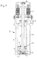
- Fig. 1
- in stark vereinfachter schematischer Darstellung einen Längsschnitt durch eine Eintauchpumpe gemäß der Erfindung,
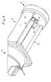
- Fig. 2
- eine perspektivische Ansicht der Pumpe nach
Fig. 1 auf den Saugmund der Pumpe, - Fig. 3
- in perspektivischer Ansicht das Drallbrecherbauteil der Pumpe gemäß den
Fig. 1 und2 , - Fig. 4
- in perspektivischer Darstellung das Pumpenlaufrad der Pumpe gemäß den
Fig. 1 und2 , - Fig. 5
- einen Schnitt durch das Pumpenlaufrad gemäß
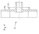
Fig. 4 , - Fig. 6
- einen Schnitt durch ein Pumpenlaufrad für eine Bauvariante der Pumpe mit nach unten gerichtetem Saugmund,
- Fig. 7
- in vergrößerter Schnittdarstellung den Boden der Pumpe nach
Fig. 1 , - Fig. 8
- den Boden der Pumpe für das Laufrad gemäß
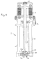
Fig. 6 mit nach unten gerichtetem Saugmund in Darstellung nachFig. 7 , und - Fig. 9
- das Pumpenaggregat mit nach unten gerichtetem Saugmund in Darstellung nach
Fig. 1 . - Bei dem in den Figuren dargestellten Pumpenaggregat handelt es sich um eine Eintauchpumpe mit einem am oberen Ende angeordneten elektrischen Antriebsmotor 1, der an einem Motorstuhl 2 befestigt ist, welcher den Antriebsmotor 1 mit einer am unteren Ende befindlichen Kreiselpumpe 3 verbindet. Bei dem anhand von
Fig. 1 dargestellten Pumpenaggregat ist der Boden 4 der Pumpe 3 geschlossen ausgebildet, wie dies im Einzelnen insbesondere ausFig. 7 hervorgeht. Der Saugmund 5 der Pumpe 3 ist zum Antriebsmotor 1 hin gerichtet, also im Betriebszustand gemäß Darstellung nachFig. 1 nach oben. - Gebildet ist der Saugmund 5 durch eine kreisrunde Öffnung in der Oberseite des Pumpengehäuses, die hier durch den Fuß des Motorstuhls 2 gebildet wird. Innerhalb dieses Pumpengehäuses ist ein Kreiselrad 6 drehbar angetrieben angeordnet, welches am Ende einer Welle 7 befestigt ist, die sich vom Antriebsmotor 1 durch den Motorstuhl 2 bis zur Pumpe 3 erstreckt. Die Welle 7 ist ausschließlich motorseitig gelagert, nämlich in einem oberen Lager 8 sowie einem unteren Lager 9, das im Motorstuhl 2 am unteren Ende des Antriebsmotors 1 angeordnet ist. Das Kreiselrad 6 ist als offenes Kreiselrad ausgebildet und weist lediglich eine Deckscheibe 10 auf, die nahe dem Boden des Pumpengehäuses angeordnet ist. Der Aufbau des Kreiselrades 6 ist im Einzelnen den
Fig. 4 und 5 zu entnehmen. Es ist am stirnseitigen unteren Ende der Welle 7 befestigt und wird von dieser getragen. - Der Saugmund 5 der Pumpe 3 wird zentral durch die Welle 7 durchsetzt, im Übrigen durch den Rand des Pumpengehäuses begrenzt. Das Pumpengehäuse wird bei der dargestellten Ausführungsform an seiner Oberseite durch den Motorstuhl 2 gebildet. Das Pumpengehäuse besteht also im Wesentlichen aus dem in
Fig. 7 dargestellten topfförmigen Gebilde und wird nach oben hin durch den Motorstuhl 2 abgeschlossen. - Der Motorstuhl 2 weist zwei bezogen auf die Achse der Welle 7 um 180° versetzt angeordnete Beine 11 und 12 auf. Während das in
Fig. 1 linke Bein 11 ausschließlich statische Funktion hat, ist das rechte Bein 12 als Druckkanal ausgebildet, verbindet also die Druckseite der Pumpe 3 mit dem ebenfalls am Motorstuhl 2 nahe des Antriebsmotors 1 angeformten Anschlussstutzen 13, welcher zum Anschluss einer Leitung dient. - Im Betrieb ist die dargestellte Pumpe 3 so angeordnet, dass die Pumpe 3 mit dem Saugmund 5 innerhalb der zu fördernden Flüssigkeit liegt, wohingegen der Antriebsmotor 1 sowie auch der Anschlussstutzen 13 oberhalb des Flüssigkeitsspiegels angeordnet sind. Um zu verhindern, dass beim Fördern der Pumpe sich von der Flüssigkeitsoberfläche ausgehend in Richtung der Welle 7 zum Saugmund 5 ein trichterförmiger Einzug bildet, welcher insbesondere dazu geeignet ist, Luft in die Förderflüssigkeit einzusaugen, ist ein Drallbrecherbauteil 14 vorgesehen, das im Saugmund 5 der Pumpe 3 und zwischen den Beinen 11 und 12 des Motorstuhls 2 befestigt ist.
- Dieses Drallbrecherbauteil 14 ist als Kunststoffspritzgussteil einstückig ausgebildet und klemmbefestigt. Es weist zwei Drallbrecher 15 und 16 auf, die an einem gemeinsamen ringförmigen Teil 17 angeformt, d. h. befestigt sind. Das ringförmige Teil 17 ist an seiner Innenseite zylindrisch ausgebildet und an der Außenseite abgestuft zylindrisch, derart, dass es in den Saugmund 5 der Pumpe 3, d. h. die entsprechende Gehäuseausnehmung im Pumpengehäuse, die hier durch die entsprechende Ausnehmung im Fuß des Motorstuhls 2 gebildet ist, einschiebbar ist. Dabei sorgt der abgestufte auskragende Teil 18 dafür, dass das Bauteil am Rand der Öffnung aufliegt, wohingegen der übrige, in die Öffnung eingreifende Teil eine radiale Abstützung bewirkt. In diesem Teil sind durch axiale Ausnehmungen Zungen 10 gebildet, die mit Rastnasen 21 versehen sind, welche beim Einstecken in die Saugmundöffnung einfedern und rückseitig verrasten und somit das Bauteil in Axialrichtung fixieren.
- Jeder der Drallbrecher 15, 16 weist einen inneren, sich von dem ringförmigen Teil 17 radial nach innen erstreckenden flächigen Schenkel 22 auf sowie einen axial fluchtend daran anschließenden flächigen äußeren Schenkel, der sich deutlich über das ringförmige Bauteil 17 hinaus in Richtung zum Antriebsmotor erstreckt und einerseits bis nahe zu dem Bein 11 reicht und andererseits, nämlich an dem den Druckkanal bildenden Bein 12 mittels eines dort angeformten, im Querschnitt c-förmigen Formschlusselements 24, das Bein 12 des Motorstuhls 2 um etwa 180° umgreift und damit das Drallbrecherbauteil 14 drehsichert. Die Drallbrecher 15 und 16 erstrecken sich somit nach innen hin bis nahe zur Welle 7 und nach außen hin bis nahe zum Bein 11 bzw. an das Bein 12 heran. Aufgrund der vorbeschriebenen Formgebung kann dieses Drallbrecherbauteil 14 durch einfaches Einklicken befestigt werden, und hält sich dann selbsttätig in dieser Stellung. Durch die beiden flächigen Drallbrecher 15 und 16, die bis in den Saugmund 5 reichen und nach oben hin, also zum Antriebsmotor 1 hin sich flächig erstrecken, kann die ungewünschte drallbedingte Wirbelbildung im Ansaugbereich wirksam verhindert werden.
- Wie anhand von
Fig. 1 durch die schraffierten Flächen 28 dargestellt, kann das Drallbrecherbauteil 14 mit einer Schutzabdeckung 28 versehen sein, welche sich die Welle 7 umgebend ringförmig bis zu den Beinen 11, 12 erstreckt. Diese Schutzabdeckung kann siebartig ausgebildet sein, also Durchbrechungen aufweisen und dient dazu, zu verhindern, dass Teile, die versehentlich von oben in Richtung zum Saugmund 5 fallen, in das Innere der Pumpe gelangen. Diese Schutzabdeckung, die den Saugmund 5 mit Abstand überdeckt, ist beispielhaft nur inFig. 1 dargestellt, die weiteren Darstellungen zeigen ein Drallbrecherbauteil 14 ohne eine solche Schutzabdeckung. - Das Drallbrecherbauteil 14 ist im Bereich des ringförmigen Teils 17 so dimensioniert, dass der in das Pumpengehäuse eingreifende Teil bis unmittelbar vor das Kreiselrad 5 reicht, sodass die stirnseitige Fläche 27 eine Dichtfläche zwischen Saug- und Druckteil der Pumpe bildet. Diese bis an das Kreiselrad 6 herangeführte Dichtfläche 27 erhöht den Wirkungsgrad der Pumpe und ist Teil des Drallbrecherbauteils 14. Wenn im Bereich der Dichtfläche 27 verschleißbedingt ein Austausch erforderlich ist, so ist lediglich das kostengünstige und als Spritzgussbauteil gefertigte Drallbrecherbauteil 14 zu tauschen.
- Wie die Ausführung des Anhand von
Fig. 9 dargestellten Pumpenaggregats zeigt, kann ohne dieses Drallbrecherbauteil 14 mit nur geringfügigen konstruktiven Änderungen mit praktisch den gleichen Bauteilen ein Pumpenaggregat geschaffen werden, welches einen nach unten gerichteten Saugmund 5a aufweist. Hierzu ist zunächst der Boden des Pumpengehäuses entsprechend auszubilden, d. h. mit einer Saugöffnung zu versehen, wie dies inFig. 8 dargestellt ist. Weiterhin ist das Kreiselrad 6a, wie inFig. 6 dargestellt, konstruktiv anzupassen. Wie ein Vergleich derFig. 5 und6 verdeutlicht, ist allerdings nur die Deckscheibe 10 bzw. 10a inFig. 6 anders auszubilden, nämlich mit einem rückseitigen Ring 25, darüber hinaus ist die Aufnahme für das Ende der Welle 7 entsprechend zu verlängern. Die Anordnung und Ausbildung der Schaufeln selbst kann unverändert bleiben. Weiterhin unverändert bleiben Antriebsmotor 1 und Motorstuhl 2, soweit es die gussformseitige Ausbildung angeht. Es ist lediglich eine ringförmige Nut 26 in der unteren Stirnseite des Motorstuhls 2 einzubringen, um die durch den Ring 25 und die Nut 26 gebildete Labyrinthdichtung zu bilden. Da die die Oberseite des Pumpengehäuses bildende Unterseite des Motorstuhls 2 ohnehin spanend zu bearbeiten ist, um eine plane Anlagefläche zu erhalten, kann die Ringnut 26 mit fertigungstechnisch praktisch geringem Mehraufwand eingebracht werden, ohne dass zusätzliche Rüstzeiten entstehen. Entsprechendes gilt für die Deckscheibenbearbeitung sowie die Bearbeitung des Pumpengehäuses. - Wie die vorstehenden Ausführungen verdeutlichen, kann durch das einklickbare Drallbrecherbauteil 14 der Motorstuhl 2 sowohl für eine Pumpenausführung mit Saugmund oben als auch für eine Pumpenausführung mit Saugmund unten eingesetzt werden. Die fertigungstechnischen Änderungen von Pumpenlaufrad und Pumpengehäuse sind denkbar gering.
- Darüber hinaus kann das erfindungsgemäße Drallbrecherbauteil 14, sofern gewünscht, auch an der Unterseite, d. h. am Saugmund 5a angebracht werden, um bei einer Saugmundanordnung an der Unterseite, wie sie in
Fig. 9 dargestellt ist, die Ansaugwirbelbildung nach unten zu verringern. -
- 1 -
- Antriebsmotor
- 2 -
- Motorstuhl
- 3 -
- Kreiselpumpe
- 4 -
- Boden
- 5 -
- Saugmund
- 5a -
- Saugmund nach unten
- 6 -
- Kreiselrad
- 6a -
- Kreiselrad für Saugmund nach unten
- 7 -
- Welle
- 8 -
- Lager oben
- 9 -
- Lager unten
- 10 -
- Deckscheibe des Kreiselrades
- 10a -
- Deckscheibe des Kreiselrades 6a
- 11 -
- Bein
- 12 -
- Bein, Druckkanal
- 13 -
- Anschlussstutzen
- 14 -
- Drallbrecherbauteil
- 15 -
- Drallbrecher
- 16 -
- Drallbrecher
- 17 -
- ringförmiges Teil
- 18 -
- auskragendes Teil
- 19 -
- axiale Ausnehmungen
- 20 -
- Zungen
- 21 -
- Rastnasen
- 22 -
- innerer Schenkel
- 23 -
- äußerer Schenkel
- 24 -
- c-förmiges Formschlusselement
- 25 -
- Ring
- 26 -
- ringförmige Nut
- 27 -
- Dichtfläche
- 28 -
- Schutzabdeckung
Claims (17)
- Pumpenaggregat mit einem elektrischen Antriebsmotor (1) und einer Kreiselpumpe (3) in Form einer Tauchpumpe, mit einem Saugmund (5) und einem dem Saugmund (5) vorgeschalteten Drallbrecher (15, 16), dadurch gekennzeichnet, dass der Drallbrecher (15, 16) durch mindestens ein Bauteil (14) gebildet ist, welches lösbar am Pumpenaggregat befestigt ist.
- Pumpenaggregat nach Anspruch 1, dadurch gekennzeichnet, dass Motor (1) und Pumpe (3) durch einen Motorstuhl (2) beabstandet verbunden sind, dass der Motorstuhl (2) mindestens ein Bein (12) aufweist, welches die Druckseite der Pumpe (3) mit einem motornah angeordneten Leitungsanschluss (13) des Pumpenaggregats leitungsverbindet, dass der Saugmund (5) zum Motor (1) hin gerichtet ist und dass das mindestens eine Drallbrecherbauteil (14) an dem Motorstuhl (2) und/oder der Pumpe (3) befestigt ist.
- Pumpenaggregat nach Anspruch 1 oder 2, dadurch gekennzeichnet, dass der Motorstuhl (2) zwei bezogen auf die Wellenachse des Motors (1) gegenüberliegend angeordnete Beine (11, 12) aufweist.
- Pumpenaggregat nach einem der vorhergehenden Ansprüche, dadurch gekennzeichnet, dass das mindestens eine Drallbrecherbauteil (14) zwischen den Beinen (11, 12) des Motorstuhls (2) klemmbefestigt ist.
- Pumpenaggregat nach einem der vorhergehenden Ansprüche, dadurch gekennzeichnet, dass das Drallbrecherbauteil (14) einen ringförmigen Befestigungsabschnitt (17) aufweist, der in den Saugmund (5) der Pumpe (3) eingreift.
- Pumpenaggregat nach einem der vorhergehenden Ansprüche, dadurch gekennzeichnet, dass das Drallbrecherbauteil (14) einen klammerförmigen Befestigungsabschnitt (24) aufweist, der mindestens ein Bein (12) des Motorstuhls (2) zumindest abschnittsweise umgreift.
- Pumpenaggregat nach einem der vorhergehenden Ansprüche, dadurch gekennzeichnet, dass der ringförmige Befestigungsabschnitt (17) vorzugsweise durch Ausnehmungen (19) gebildete Rastzungen (20) aufweist, mit denen das Drallbrecherbauteil (14) rastend in einer den Saugmund (5) bildenden Öffnung des Pumpengehäuses festlegbar ist.
- Pumpenaggregat nach einem der vorhergehenden Ansprüche, dadurch gekennzeichnet, dass der Drallbrecher (15, 16) einen flächigen inneren Schenkel (22) aufweist, der sich vom Rand des Saugmunds (5) radial nach innen erstreckt
- Pumpenaggregat nach einem der vorhergehenden Ansprüche, dadurch gekennzeichnet, dass der innere Schenkel (22) an der Innenseite des ringförmigen Bauteils (17) angeformt ist.
- Pumpenaggregat nach einem der vorhergehenden Ansprüche, dadurch gekennzeichnet, dass der Drallbrecher (15, 16) einen flächigen äußeren Schenkel (23) aufweist, der sich außerhalb des Saugmunds (5) vorzugsweise in Richtung zum Motor (1) erstreckt, und zwar radial zwischen Welle (7) und einem Bein (11, 12) des Motorstuhls (2).
- Pumpenaggregat nach einem der vorhergehenden Ansprüche, dadurch gekennzeichnet, dass sich der innere Schenkel (22) in Achsrichtung der Welle (7) gesehen in Flucht zu dem äußeren Schenkel (23) liegt und axial an diesen anschließt.
- Pumpenaggregat nach einem der vorhergehenden Ansprüche, dadurch gekennzeichnet, dass der äußere Schenkel (23) an der Oberseite des ringförmigen Bauteils (17) angeformt ist.
- Pumpenaggregat nach einem der vorhergehenden Ansprüche, dadurch gekennzeichnet, dass mehrere Drallbrecher (15, 16) mittels eines Verbindungselement (17) zu einem Drallbrecherbauteil (14) verbunden sind.
- Pumpenaggregat nach einem der vorhergehenden Ansprüche, dadurch gekennzeichnet, dass das Drallbrecherbauteil (14) eine Dichtung zwischen Saug- und Druckseite der Pumpe (3) bildet.
- Pumpenaggregat nach einem der vorhergehenden Ansprüche, dadurch gekennzeichnet, dass der in die Öffnung des Pumpengehäuses eingreifende Teil des ringförmigen Bauteils (17) eine Stirnfläche (27) aufweist, welche eine Dichtfläche bildet.
- Pumpenaggregat nach einem der vorhergehenden Ansprüche, dadurch gekennzeichnet, dass das Drallbrecherbauteil (14) eine den Saugmund (5) der Pumpe (3) zumindest teilweise mit Abstand überdeckende Schutzabdeckung (28) aufweist.
- Pumpenaggregat nach einem der vorhergehenden Ansprüche, dadurch gekennzeichnet, dass das Drallbrecherbauteil (14) durch ein einstückiges Spritzgussbauteil gebildet ist.
Priority Applications (3)
| Application Number | Priority Date | Filing Date | Title |
|---|---|---|---|
| EP11003736.3A EP2520806B1 (de) | 2011-05-06 | 2011-05-06 | Pumpenaggregat |
| PCT/EP2012/057731 WO2012152599A1 (de) | 2011-05-06 | 2012-04-27 | Pumpenaggregat |
| KR1020137031939A KR101889829B1 (ko) | 2011-05-06 | 2012-04-27 | 펌프 조립체 |
Applications Claiming Priority (1)
| Application Number | Priority Date | Filing Date | Title |
|---|---|---|---|
| EP11003736.3A EP2520806B1 (de) | 2011-05-06 | 2011-05-06 | Pumpenaggregat |
Publications (2)
| Publication Number | Publication Date |
|---|---|
| EP2520806A1 true EP2520806A1 (de) | 2012-11-07 |
| EP2520806B1 EP2520806B1 (de) | 2018-07-11 |
Family
ID=44736121
Family Applications (1)
| Application Number | Title | Priority Date | Filing Date |
|---|---|---|---|
| EP11003736.3A Not-in-force EP2520806B1 (de) | 2011-05-06 | 2011-05-06 | Pumpenaggregat |
Country Status (3)
| Country | Link |
|---|---|
| EP (1) | EP2520806B1 (de) |
| KR (1) | KR101889829B1 (de) |
| WO (1) | WO2012152599A1 (de) |
Cited By (2)
| Publication number | Priority date | Publication date | Assignee | Title |
|---|---|---|---|---|
| ITMI20130390A1 (it) * | 2013-03-15 | 2014-09-16 | Euroacque S R L | Pompa disincrostatrice |
| JP2014202128A (ja) * | 2013-04-04 | 2014-10-27 | Kawamoto Gec株式会社 | ポンプ装置のケーシング |
Families Citing this family (2)
| Publication number | Priority date | Publication date | Assignee | Title |
|---|---|---|---|---|
| KR102422187B1 (ko) * | 2020-10-30 | 2022-07-18 | (주)스텝이엔지 | 강판 용융아연도금 공정에서의 스나우트의 내부 이물제거장치 |
| WO2022092592A1 (ko) * | 2020-10-30 | 2022-05-05 | (주)스텝이엔지 | 강판 용융아연도금 공정에서의 스나우트의 내부 이물제거장치 |
Citations (4)
| Publication number | Priority date | Publication date | Assignee | Title |
|---|---|---|---|---|
| JPS57143190A (en) * | 1981-02-27 | 1982-09-04 | Hitachi Ltd | Electrically operated submerged pump |
| JPH07293496A (ja) * | 1994-04-27 | 1995-11-07 | Terada Pump Seisakusho:Kk | 水中ポンプ |
| EP1898100A1 (de) * | 2006-08-18 | 2008-03-12 | H.H. Idé v/ Henrik Hoffmann | Fluidleitvorrichtung |
| JP2010190184A (ja) * | 2009-02-20 | 2010-09-02 | Torishima Pump Mfg Co Ltd | ポンプ用吸込渦防止部材 |
-
2011
- 2011-05-06 EP EP11003736.3A patent/EP2520806B1/de not_active Not-in-force
-
2012
- 2012-04-27 KR KR1020137031939A patent/KR101889829B1/ko not_active Expired - Fee Related
- 2012-04-27 WO PCT/EP2012/057731 patent/WO2012152599A1/de not_active Ceased
Patent Citations (4)
| Publication number | Priority date | Publication date | Assignee | Title |
|---|---|---|---|---|
| JPS57143190A (en) * | 1981-02-27 | 1982-09-04 | Hitachi Ltd | Electrically operated submerged pump |
| JPH07293496A (ja) * | 1994-04-27 | 1995-11-07 | Terada Pump Seisakusho:Kk | 水中ポンプ |
| EP1898100A1 (de) * | 2006-08-18 | 2008-03-12 | H.H. Idé v/ Henrik Hoffmann | Fluidleitvorrichtung |
| JP2010190184A (ja) * | 2009-02-20 | 2010-09-02 | Torishima Pump Mfg Co Ltd | ポンプ用吸込渦防止部材 |
Cited By (2)
| Publication number | Priority date | Publication date | Assignee | Title |
|---|---|---|---|---|
| ITMI20130390A1 (it) * | 2013-03-15 | 2014-09-16 | Euroacque S R L | Pompa disincrostatrice |
| JP2014202128A (ja) * | 2013-04-04 | 2014-10-27 | Kawamoto Gec株式会社 | ポンプ装置のケーシング |
Also Published As
| Publication number | Publication date |
|---|---|
| KR20140028047A (ko) | 2014-03-07 |
| KR101889829B1 (ko) | 2018-08-21 |
| EP2520806B1 (de) | 2018-07-11 |
| WO2012152599A1 (de) | 2012-11-15 |
Similar Documents
| Publication | Publication Date | Title |
|---|---|---|
| EP2495444B1 (de) | Pumpe | |
| EP2818721B1 (de) | Kreiselpumpe | |
| EP2628958A2 (de) | Leitrad für eine Impellerpumpe und Impellerpumpe | |
| DE102005014348B3 (de) | Pumpe mit Schneidlaufrad und Vorzerkleinerer | |
| EP2905472B1 (de) | Naßlaufkreiselpumpe | |
| EP2708754A2 (de) | Pumpe | |
| DE4428633C2 (de) | Peripheralpumpe zum Zuführen von Kraftstoff zu einem Fahrzeugmotor | |
| EP2520806B1 (de) | Pumpenaggregat | |
| EP1760322B1 (de) | Pumpe für Teich-, Aquarien- oder dergleichen Anlagen | |
| EP2143955B1 (de) | Bohrlochpumpe | |
| EP1213517B1 (de) | Gleitringdichtung für Strömungsmaschinen | |
| DE202017006981U1 (de) | Verbesserter Elektromotor für einen Fluidzirkulator | |
| DE10024741B4 (de) | Seitenkanalpumpe | |
| DE102005036818B4 (de) | Pumpengehäuse, Pumpe und wasserführendes Haushaltsgerät | |
| DE102008057849A1 (de) | Schneidvorrichtung einer Pumpe | |
| EP2072827A1 (de) | Spaltrohrmotorpumpe | |
| EP2513483B1 (de) | Kraftstoffpumpe | |
| EP1217217B1 (de) | Hauswasserwerk | |
| DE10019819A1 (de) | Pumpe, insbesondere Umwälzpumpe für Haushaltsmaschinen wie Geschirrspülmaschinen | |
| DE102005042228B4 (de) | Saugmaschine | |
| EP3853480B1 (de) | Pumpenanordnung | |
| EP2971788B1 (de) | Lagerschild für einen gebläsemotor eines radialgebläses einer dunstabzugshaube | |
| WO2015144307A1 (de) | Kreiselpumpe mit schneidvorrichtung | |
| EP0995906A1 (de) | Motorgetriebene Doppelpumpe der Kreiselpumpenbauart | |
| DE3520362A1 (de) | Aquarienpumpe |
Legal Events
| Date | Code | Title | Description |
|---|---|---|---|
| PUAI | Public reference made under article 153(3) epc to a published international application that has entered the european phase |
Free format text: ORIGINAL CODE: 0009012 |
|
| AK | Designated contracting states |
Kind code of ref document: A1 Designated state(s): AL AT BE BG CH CY CZ DE DK EE ES FI FR GB GR HR HU IE IS IT LI LT LU LV MC MK MT NL NO PL PT RO RS SE SI SK SM TR |
|
| AX | Request for extension of the european patent |
Extension state: BA ME |
|
| 17P | Request for examination filed |
Effective date: 20130506 |
|
| GRAP | Despatch of communication of intention to grant a patent |
Free format text: ORIGINAL CODE: EPIDOSNIGR1 |
|
| STAA | Information on the status of an ep patent application or granted ep patent |
Free format text: STATUS: GRANT OF PATENT IS INTENDED |
|
| INTG | Intention to grant announced |
Effective date: 20180123 |
|
| GRAJ | Information related to disapproval of communication of intention to grant by the applicant or resumption of examination proceedings by the epo deleted |
Free format text: ORIGINAL CODE: EPIDOSDIGR1 |
|
| STAA | Information on the status of an ep patent application or granted ep patent |
Free format text: STATUS: REQUEST FOR EXAMINATION WAS MADE |
|
| GRAR | Information related to intention to grant a patent recorded |
Free format text: ORIGINAL CODE: EPIDOSNIGR71 |
|
| GRAS | Grant fee paid |
Free format text: ORIGINAL CODE: EPIDOSNIGR3 |
|
| STAA | Information on the status of an ep patent application or granted ep patent |
Free format text: STATUS: GRANT OF PATENT IS INTENDED |
|
| GRAA | (expected) grant |
Free format text: ORIGINAL CODE: 0009210 |
|
| STAA | Information on the status of an ep patent application or granted ep patent |
Free format text: STATUS: THE PATENT HAS BEEN GRANTED |
|
| INTC | Intention to grant announced (deleted) | ||
| INTG | Intention to grant announced |
Effective date: 20180530 |
|
| AK | Designated contracting states |
Kind code of ref document: B1 Designated state(s): AL AT BE BG CH CY CZ DE DK EE ES FI FR GB GR HR HU IE IS IT LI LT LU LV MC MK MT NL NO PL PT RO RS SE SI SK SM TR |
|
| REG | Reference to a national code |
Ref country code: GB Ref legal event code: FG4D Free format text: NOT ENGLISH |
|
| REG | Reference to a national code |
Ref country code: CH Ref legal event code: EP |
|
| REG | Reference to a national code |
Ref country code: AT Ref legal event code: REF Ref document number: 1017166 Country of ref document: AT Kind code of ref document: T Effective date: 20180715 |
|
| REG | Reference to a national code |
Ref country code: DE Ref legal event code: R096 Ref document number: 502011014420 Country of ref document: DE |
|
| REG | Reference to a national code |
Ref country code: IE Ref legal event code: FG4D Free format text: LANGUAGE OF EP DOCUMENT: GERMAN |
|
| REG | Reference to a national code |
Ref country code: NL Ref legal event code: MP Effective date: 20180711 |
|
| REG | Reference to a national code |
Ref country code: LT Ref legal event code: MG4D |
|
| PG25 | Lapsed in a contracting state [announced via postgrant information from national office to epo] |
Ref country code: NL Free format text: LAPSE BECAUSE OF FAILURE TO SUBMIT A TRANSLATION OF THE DESCRIPTION OR TO PAY THE FEE WITHIN THE PRESCRIBED TIME-LIMIT Effective date: 20180711 |
|
| PG25 | Lapsed in a contracting state [announced via postgrant information from national office to epo] |
Ref country code: FI Free format text: LAPSE BECAUSE OF FAILURE TO SUBMIT A TRANSLATION OF THE DESCRIPTION OR TO PAY THE FEE WITHIN THE PRESCRIBED TIME-LIMIT Effective date: 20180711 Ref country code: PL Free format text: LAPSE BECAUSE OF FAILURE TO SUBMIT A TRANSLATION OF THE DESCRIPTION OR TO PAY THE FEE WITHIN THE PRESCRIBED TIME-LIMIT Effective date: 20180711 Ref country code: LT Free format text: LAPSE BECAUSE OF FAILURE TO SUBMIT A TRANSLATION OF THE DESCRIPTION OR TO PAY THE FEE WITHIN THE PRESCRIBED TIME-LIMIT Effective date: 20180711 Ref country code: BG Free format text: LAPSE BECAUSE OF FAILURE TO SUBMIT A TRANSLATION OF THE DESCRIPTION OR TO PAY THE FEE WITHIN THE PRESCRIBED TIME-LIMIT Effective date: 20181011 Ref country code: GR Free format text: LAPSE BECAUSE OF FAILURE TO SUBMIT A TRANSLATION OF THE DESCRIPTION OR TO PAY THE FEE WITHIN THE PRESCRIBED TIME-LIMIT Effective date: 20181012 Ref country code: NO Free format text: LAPSE BECAUSE OF FAILURE TO SUBMIT A TRANSLATION OF THE DESCRIPTION OR TO PAY THE FEE WITHIN THE PRESCRIBED TIME-LIMIT Effective date: 20181011 Ref country code: IS Free format text: LAPSE BECAUSE OF FAILURE TO SUBMIT A TRANSLATION OF THE DESCRIPTION OR TO PAY THE FEE WITHIN THE PRESCRIBED TIME-LIMIT Effective date: 20181111 Ref country code: RS Free format text: LAPSE BECAUSE OF FAILURE TO SUBMIT A TRANSLATION OF THE DESCRIPTION OR TO PAY THE FEE WITHIN THE PRESCRIBED TIME-LIMIT Effective date: 20180711 Ref country code: SE Free format text: LAPSE BECAUSE OF FAILURE TO SUBMIT A TRANSLATION OF THE DESCRIPTION OR TO PAY THE FEE WITHIN THE PRESCRIBED TIME-LIMIT Effective date: 20180711 |
|
| PG25 | Lapsed in a contracting state [announced via postgrant information from national office to epo] |
Ref country code: ES Free format text: LAPSE BECAUSE OF FAILURE TO SUBMIT A TRANSLATION OF THE DESCRIPTION OR TO PAY THE FEE WITHIN THE PRESCRIBED TIME-LIMIT Effective date: 20180711 Ref country code: AL Free format text: LAPSE BECAUSE OF FAILURE TO SUBMIT A TRANSLATION OF THE DESCRIPTION OR TO PAY THE FEE WITHIN THE PRESCRIBED TIME-LIMIT Effective date: 20180711 Ref country code: LV Free format text: LAPSE BECAUSE OF FAILURE TO SUBMIT A TRANSLATION OF THE DESCRIPTION OR TO PAY THE FEE WITHIN THE PRESCRIBED TIME-LIMIT Effective date: 20180711 Ref country code: HR Free format text: LAPSE BECAUSE OF FAILURE TO SUBMIT A TRANSLATION OF THE DESCRIPTION OR TO PAY THE FEE WITHIN THE PRESCRIBED TIME-LIMIT Effective date: 20180711 |
|
| REG | Reference to a national code |
Ref country code: DE Ref legal event code: R097 Ref document number: 502011014420 Country of ref document: DE |
|
| PG25 | Lapsed in a contracting state [announced via postgrant information from national office to epo] |
Ref country code: IT Free format text: LAPSE BECAUSE OF FAILURE TO SUBMIT A TRANSLATION OF THE DESCRIPTION OR TO PAY THE FEE WITHIN THE PRESCRIBED TIME-LIMIT Effective date: 20180711 Ref country code: EE Free format text: LAPSE BECAUSE OF FAILURE TO SUBMIT A TRANSLATION OF THE DESCRIPTION OR TO PAY THE FEE WITHIN THE PRESCRIBED TIME-LIMIT Effective date: 20180711 Ref country code: RO Free format text: LAPSE BECAUSE OF FAILURE TO SUBMIT A TRANSLATION OF THE DESCRIPTION OR TO PAY THE FEE WITHIN THE PRESCRIBED TIME-LIMIT Effective date: 20180711 Ref country code: CZ Free format text: LAPSE BECAUSE OF FAILURE TO SUBMIT A TRANSLATION OF THE DESCRIPTION OR TO PAY THE FEE WITHIN THE PRESCRIBED TIME-LIMIT Effective date: 20180711 |
|
| PLBE | No opposition filed within time limit |
Free format text: ORIGINAL CODE: 0009261 |
|
| STAA | Information on the status of an ep patent application or granted ep patent |
Free format text: STATUS: NO OPPOSITION FILED WITHIN TIME LIMIT |
|
| PG25 | Lapsed in a contracting state [announced via postgrant information from national office to epo] |
Ref country code: DK Free format text: LAPSE BECAUSE OF FAILURE TO SUBMIT A TRANSLATION OF THE DESCRIPTION OR TO PAY THE FEE WITHIN THE PRESCRIBED TIME-LIMIT Effective date: 20180711 Ref country code: SK Free format text: LAPSE BECAUSE OF FAILURE TO SUBMIT A TRANSLATION OF THE DESCRIPTION OR TO PAY THE FEE WITHIN THE PRESCRIBED TIME-LIMIT Effective date: 20180711 Ref country code: SM Free format text: LAPSE BECAUSE OF FAILURE TO SUBMIT A TRANSLATION OF THE DESCRIPTION OR TO PAY THE FEE WITHIN THE PRESCRIBED TIME-LIMIT Effective date: 20180711 |
|
| 26N | No opposition filed |
Effective date: 20190412 |
|
| PG25 | Lapsed in a contracting state [announced via postgrant information from national office to epo] |
Ref country code: SI Free format text: LAPSE BECAUSE OF FAILURE TO SUBMIT A TRANSLATION OF THE DESCRIPTION OR TO PAY THE FEE WITHIN THE PRESCRIBED TIME-LIMIT Effective date: 20180711 |
|
| REG | Reference to a national code |
Ref country code: CH Ref legal event code: PL |
|
| PG25 | Lapsed in a contracting state [announced via postgrant information from national office to epo] |
Ref country code: MC Free format text: LAPSE BECAUSE OF FAILURE TO SUBMIT A TRANSLATION OF THE DESCRIPTION OR TO PAY THE FEE WITHIN THE PRESCRIBED TIME-LIMIT Effective date: 20180711 Ref country code: CH Free format text: LAPSE BECAUSE OF NON-PAYMENT OF DUE FEES Effective date: 20190531 Ref country code: LI Free format text: LAPSE BECAUSE OF NON-PAYMENT OF DUE FEES Effective date: 20190531 |
|
| REG | Reference to a national code |
Ref country code: BE Ref legal event code: MM Effective date: 20190531 |
|
| PG25 | Lapsed in a contracting state [announced via postgrant information from national office to epo] |
Ref country code: LU Free format text: LAPSE BECAUSE OF NON-PAYMENT OF DUE FEES Effective date: 20190506 |
|
| PG25 | Lapsed in a contracting state [announced via postgrant information from national office to epo] |
Ref country code: TR Free format text: LAPSE BECAUSE OF FAILURE TO SUBMIT A TRANSLATION OF THE DESCRIPTION OR TO PAY THE FEE WITHIN THE PRESCRIBED TIME-LIMIT Effective date: 20180711 |
|
| PG25 | Lapsed in a contracting state [announced via postgrant information from national office to epo] |
Ref country code: IE Free format text: LAPSE BECAUSE OF NON-PAYMENT OF DUE FEES Effective date: 20190506 |
|
| PG25 | Lapsed in a contracting state [announced via postgrant information from national office to epo] |
Ref country code: BE Free format text: LAPSE BECAUSE OF NON-PAYMENT OF DUE FEES Effective date: 20190531 |
|
| PG25 | Lapsed in a contracting state [announced via postgrant information from national office to epo] |
Ref country code: PT Free format text: LAPSE BECAUSE OF FAILURE TO SUBMIT A TRANSLATION OF THE DESCRIPTION OR TO PAY THE FEE WITHIN THE PRESCRIBED TIME-LIMIT Effective date: 20181111 |
|
| REG | Reference to a national code |
Ref country code: AT Ref legal event code: MM01 Ref document number: 1017166 Country of ref document: AT Kind code of ref document: T Effective date: 20190506 |
|
| PG25 | Lapsed in a contracting state [announced via postgrant information from national office to epo] |
Ref country code: AT Free format text: LAPSE BECAUSE OF NON-PAYMENT OF DUE FEES Effective date: 20190506 |
|
| PG25 | Lapsed in a contracting state [announced via postgrant information from national office to epo] |
Ref country code: CY Free format text: LAPSE BECAUSE OF FAILURE TO SUBMIT A TRANSLATION OF THE DESCRIPTION OR TO PAY THE FEE WITHIN THE PRESCRIBED TIME-LIMIT Effective date: 20180711 |
|
| PG25 | Lapsed in a contracting state [announced via postgrant information from national office to epo] |
Ref country code: MT Free format text: LAPSE BECAUSE OF FAILURE TO SUBMIT A TRANSLATION OF THE DESCRIPTION OR TO PAY THE FEE WITHIN THE PRESCRIBED TIME-LIMIT Effective date: 20180711 Ref country code: HU Free format text: LAPSE BECAUSE OF FAILURE TO SUBMIT A TRANSLATION OF THE DESCRIPTION OR TO PAY THE FEE WITHIN THE PRESCRIBED TIME-LIMIT; INVALID AB INITIO Effective date: 20110506 |
|
| PGFP | Annual fee paid to national office [announced via postgrant information from national office to epo] |
Ref country code: DE Payment date: 20210525 Year of fee payment: 11 Ref country code: FR Payment date: 20210521 Year of fee payment: 11 |
|
| PGFP | Annual fee paid to national office [announced via postgrant information from national office to epo] |
Ref country code: GB Payment date: 20210525 Year of fee payment: 11 |
|
| PG25 | Lapsed in a contracting state [announced via postgrant information from national office to epo] |
Ref country code: MK Free format text: LAPSE BECAUSE OF FAILURE TO SUBMIT A TRANSLATION OF THE DESCRIPTION OR TO PAY THE FEE WITHIN THE PRESCRIBED TIME-LIMIT Effective date: 20180711 |
|
| REG | Reference to a national code |
Ref country code: DE Ref legal event code: R119 Ref document number: 502011014420 Country of ref document: DE |
|
| GBPC | Gb: european patent ceased through non-payment of renewal fee |
Effective date: 20220506 |
|
| PG25 | Lapsed in a contracting state [announced via postgrant information from national office to epo] |
Ref country code: FR Free format text: LAPSE BECAUSE OF NON-PAYMENT OF DUE FEES Effective date: 20220531 |
|
| PG25 | Lapsed in a contracting state [announced via postgrant information from national office to epo] |
Ref country code: GB Free format text: LAPSE BECAUSE OF NON-PAYMENT OF DUE FEES Effective date: 20220506 Ref country code: DE Free format text: LAPSE BECAUSE OF NON-PAYMENT OF DUE FEES Effective date: 20221201 |