EP2518399A2 - Leuchte - Google Patents
Leuchte Download PDFInfo
- Publication number
- EP2518399A2 EP2518399A2 EP12165453A EP12165453A EP2518399A2 EP 2518399 A2 EP2518399 A2 EP 2518399A2 EP 12165453 A EP12165453 A EP 12165453A EP 12165453 A EP12165453 A EP 12165453A EP 2518399 A2 EP2518399 A2 EP 2518399A2
- Authority
- EP
- European Patent Office
- Prior art keywords
- housing
- thread
- cover
- luminaire according
- sealing sleeve
- Prior art date
- Legal status (The legal status is an assumption and is not a legal conclusion. Google has not performed a legal analysis and makes no representation as to the accuracy of the status listed.)
- Granted
Links
- 238000007789 sealing Methods 0.000 claims abstract description 45
- 239000000853 adhesive Substances 0.000 claims description 3
- 230000001070 adhesive effect Effects 0.000 claims description 3
- XAGFODPZIPBFFR-UHFFFAOYSA-N aluminium Chemical compound [Al] XAGFODPZIPBFFR-UHFFFAOYSA-N 0.000 description 2
- 229910052782 aluminium Inorganic materials 0.000 description 2
- 239000012207 thread-locking agent Substances 0.000 description 2
- 230000001419 dependent effect Effects 0.000 description 1
- 238000011161 development Methods 0.000 description 1
- 230000018109 developmental process Effects 0.000 description 1
- 230000007613 environmental effect Effects 0.000 description 1
- 239000011521 glass Substances 0.000 description 1
- 238000012423 maintenance Methods 0.000 description 1
- 238000004519 manufacturing process Methods 0.000 description 1
- 230000007704 transition Effects 0.000 description 1
Images
Classifications
-
- F—MECHANICAL ENGINEERING; LIGHTING; HEATING; WEAPONS; BLASTING
- F21—LIGHTING
- F21V—FUNCTIONAL FEATURES OR DETAILS OF LIGHTING DEVICES OR SYSTEMS THEREOF; STRUCTURAL COMBINATIONS OF LIGHTING DEVICES WITH OTHER ARTICLES, NOT OTHERWISE PROVIDED FOR
- F21V17/00—Fastening of component parts of lighting devices, e.g. shades, globes, refractors, reflectors, filters, screens, grids or protective cages
- F21V17/10—Fastening of component parts of lighting devices, e.g. shades, globes, refractors, reflectors, filters, screens, grids or protective cages characterised by specific fastening means or way of fastening
- F21V17/12—Fastening of component parts of lighting devices, e.g. shades, globes, refractors, reflectors, filters, screens, grids or protective cages characterised by specific fastening means or way of fastening by screwing
-
- F—MECHANICAL ENGINEERING; LIGHTING; HEATING; WEAPONS; BLASTING
- F21—LIGHTING
- F21V—FUNCTIONAL FEATURES OR DETAILS OF LIGHTING DEVICES OR SYSTEMS THEREOF; STRUCTURAL COMBINATIONS OF LIGHTING DEVICES WITH OTHER ARTICLES, NOT OTHERWISE PROVIDED FOR
- F21V15/00—Protecting lighting devices from damage
- F21V15/01—Housings, e.g. material or assembling of housing parts
-
- F—MECHANICAL ENGINEERING; LIGHTING; HEATING; WEAPONS; BLASTING
- F21—LIGHTING
- F21V—FUNCTIONAL FEATURES OR DETAILS OF LIGHTING DEVICES OR SYSTEMS THEREOF; STRUCTURAL COMBINATIONS OF LIGHTING DEVICES WITH OTHER ARTICLES, NOT OTHERWISE PROVIDED FOR
- F21V23/00—Arrangement of electric circuit elements in or on lighting devices
- F21V23/003—Arrangement of electric circuit elements in or on lighting devices the elements being electronics drivers or controllers for operating the light source, e.g. for a LED array
- F21V23/007—Arrangement of electric circuit elements in or on lighting devices the elements being electronics drivers or controllers for operating the light source, e.g. for a LED array enclosed in a casing
- F21V23/009—Arrangement of electric circuit elements in or on lighting devices the elements being electronics drivers or controllers for operating the light source, e.g. for a LED array enclosed in a casing the casing being inside the housing of the lighting device
-
- F—MECHANICAL ENGINEERING; LIGHTING; HEATING; WEAPONS; BLASTING
- F21—LIGHTING
- F21V—FUNCTIONAL FEATURES OR DETAILS OF LIGHTING DEVICES OR SYSTEMS THEREOF; STRUCTURAL COMBINATIONS OF LIGHTING DEVICES WITH OTHER ARTICLES, NOT OTHERWISE PROVIDED FOR
- F21V23/00—Arrangement of electric circuit elements in or on lighting devices
- F21V23/02—Arrangement of electric circuit elements in or on lighting devices the elements being transformers, impedances or power supply units, e.g. a transformer with a rectifier
-
- F—MECHANICAL ENGINEERING; LIGHTING; HEATING; WEAPONS; BLASTING
- F21—LIGHTING
- F21V—FUNCTIONAL FEATURES OR DETAILS OF LIGHTING DEVICES OR SYSTEMS THEREOF; STRUCTURAL COMBINATIONS OF LIGHTING DEVICES WITH OTHER ARTICLES, NOT OTHERWISE PROVIDED FOR
- F21V3/00—Globes; Bowls; Cover glasses
-
- F—MECHANICAL ENGINEERING; LIGHTING; HEATING; WEAPONS; BLASTING
- F21—LIGHTING
- F21V—FUNCTIONAL FEATURES OR DETAILS OF LIGHTING DEVICES OR SYSTEMS THEREOF; STRUCTURAL COMBINATIONS OF LIGHTING DEVICES WITH OTHER ARTICLES, NOT OTHERWISE PROVIDED FOR
- F21V31/00—Gas-tight or water-tight arrangements
- F21V31/005—Sealing arrangements therefor
-
- F—MECHANICAL ENGINEERING; LIGHTING; HEATING; WEAPONS; BLASTING
- F21—LIGHTING
- F21S—NON-PORTABLE LIGHTING DEVICES; SYSTEMS THEREOF; VEHICLE LIGHTING DEVICES SPECIALLY ADAPTED FOR VEHICLE EXTERIORS
- F21S8/00—Lighting devices intended for fixed installation
- F21S8/03—Lighting devices intended for fixed installation of surface-mounted type
- F21S8/033—Lighting devices intended for fixed installation of surface-mounted type the surface being a wall or like vertical structure, e.g. building facade
- F21S8/036—Lighting devices intended for fixed installation of surface-mounted type the surface being a wall or like vertical structure, e.g. building facade by means of a rigid support, e.g. bracket or arm
-
- F—MECHANICAL ENGINEERING; LIGHTING; HEATING; WEAPONS; BLASTING
- F21—LIGHTING
- F21W—INDEXING SCHEME ASSOCIATED WITH SUBCLASSES F21K, F21L, F21S and F21V, RELATING TO USES OR APPLICATIONS OF LIGHTING DEVICES OR SYSTEMS
- F21W2131/00—Use or application of lighting devices or systems not provided for in codes F21W2102/00-F21W2121/00
- F21W2131/10—Outdoor lighting
Definitions
- the present invention relates to a luminaire, which has a housing with at least one opening and a cover for closing the opening, wherein the cover can be fastened to the housing with at least one screw, and the housing has at least one area that coincides with a part of the housing Cover overlapped when attached.
- a housing in particular an aluminum pressure housing, which is substantially completely closed.
- an aluminum housing causes relatively high manufacturing costs and on the other hand, such a housing also means that it is possible only with relatively high effort to get to the arranged in the housing components to replace, for example, a bulb.
- the present invention is therefore an object of the invention to develop a lamp in which on the one hand a relatively easy accessibility of the components arranged in the lamp is made possible and which is designed to protect these arranged in the lamp components from external influences.
- a luminaire which has a housing with at least one opening and a cover for closing the opening, wherein the cover can be fastened to the housing with at least one screw and the housing has at least one area which coincides with a part of the cover overlapped in the attached state.
- the housing has in the region which overlaps with a part of the cover, at least one hole in which a thread seal sleeve is arranged, wherein the screw can be screwed to secure the cover in the thread seal sleeve.
- the thread sealing sleeve is arranged sealingly on the housing and the at least one sealing element is arranged in the region of the housing which overlaps with a part of the cover.
- the thread sealing sleeve consists of an elongate substantially cylindrical part with an elongated cavity, wherein the cavity has an internal thread and at one end of the cylindrical part has an opening, such that on the opening from the outside, the screw can be screwed into the internal thread, wherein the cylindrical part of the thread sealing sleeve protrudes through the hole of the housing.
- the thread sealing sleeve may have an edge running around the opening, which projects laterally outwardly beyond the cylindrical part, the edge being at the area of the housing which coincides with one Part of the cover overlaps, abuts, such that the edge forms a sealing stop for the cylindrical part.
- the cylindrical part of the thread sealing sheath has an external thread and the hole of the housing is formed as a threaded passage, wherein arranged between the edge of the thread seal sleeve and the housing and also between the external thread of the thread sealing sleeve and the thread passage of the housing a threaded adhesive is.
- the external thread it may be provided that the cylindrical part in the region following the edge is narrower in circumference than the remaining cylindrical part and has no external thread.
- the cover can also - at least partially - be designed to be transparent and have lichtbeinlende properties, wherein on the cover, a lamp unit or a device carrier may be arranged, which is / r is in the case attached to the housing cover within the housing.
- the luminaire unit may in this case comprise a luminous means and a reflector.
- a corresponding lamp unit or a corresponding device carrier is arranged within the housing in the vicinity of the opening.
- FIGS. 1 and 2 a lamp 1 according to the invention is shown, which has a housing 2, which is for example designed to be attached to a wall can.
- a housing 2 which is for example designed to be attached to a wall can.
- two openings 4 are provided in the housing 2, one of which points down and the other upwards.
- covers 3 are still provided in the luminaire 1 according to the invention.
- the covers 3 are configured in accordance with the openings 4, wherein the covers 3 are formed slightly larger, so that in the case 2 at both openings 4 each result in a region 6, which overlaps with a portion of the covers 3, when the covers 3 at be attached to the housing 2.
- the covers 3 are fastened by means of screws 5.
- a threaded sealing sleeve 8 is additionally provided, which is arranged in the holes 7.
- the thread sealing sleeve 8 is more accurate in the FIGS. 4 and 5 shown.
- the threaded sealing sleeve 8 has an elongated substantially cylindrical portion 14 in which an elongated cavity 16 is arranged.
- the cavity 16 is arranged inside the cylindrical part 14 such that an outwardly projecting opening 17 of the cavity is provided at one end of the cylindrical part 14.
- the cylindrical part 14 is closed at the other end, whereby the cavity 16 is opened only on one side.
- the cavity 16 further has an internal thread, which makes it possible that over the opening 17 from the outside, the screw 5 can be screwed into the internal thread.
- flange-like edge 15 is provided which protrudes laterally beyond the cylindrical portion 14 to the outside.
- this area 18 also has no external thread.
- the thread sealing sleeves 8 are now inserted into the holes 7, it being provided that the holes 7 are designed as threaded passages.
- the thread sealing sleeves 8 are then screwed with a threaded adhesive in the threaded passages 7, whereby after complete screwing of the thread sealing sleeves 8, the thread adhesive between the edge 15 and the housing 2 and the Gewinde trimmersn 7 and the external threads of the thread sealing sleeves 8 is arranged. This results in a tightness between the respective parts.
- the thread-sealing sleeves 8 are arranged in the threaded passages 7 such that the majority of the cylindrical portion 14 of the thread-sealing sleeves 8 is arranged in the housing 2.
- the edge 15 rests against the outside of the housing 2, whereby the edge 15 forms a sealing stop for the cylindrical part 14.
- sealing elements 13 are additionally provided, which allow a seal between the cover 3 and the housing 2 when the cover 3 is attached.
- the sealing elements 13 are arranged in the region 6 of the housing 2, which overlaps with a part of the cover 3.
- FIG. 3 shows, in which case the covers 3 are angled at their ends and engage in corresponding recesses of the housing 2.
- the cover 3 on which the luminaire unit is provided is designed to be transparent or light-influencing.
- the reflector is closed with a glass pane.
Landscapes
- Engineering & Computer Science (AREA)
- General Engineering & Computer Science (AREA)
- Microelectronics & Electronic Packaging (AREA)
- Power Engineering (AREA)
- Securing Globes, Refractors, Reflectors Or The Like (AREA)
- Arrangement Of Elements, Cooling, Sealing, Or The Like Of Lighting Devices (AREA)
Abstract
Description
- Die vorliegende Erfindung betrifft eine Leuchte, die ein Gehäuse mit mindestens einer Öffnung und eine Abdeckung zum Verschließen der Öffnung aufweist, wobei die Abdeckung mit mindestens einer Schraube an dem Gehäuse befestigt werden kann und das Gehäuse mindestens einen Bereich aufweist, der sich mit einem Teil der Abdeckung im befestigten Zustand überlappt.
- Bei Leuchten die beispielsweise im Außenbereich zum Einsatz kommen, ist es zumeist erforderlich, dass die Leuchten eine entsprechende IP-Schutzklasse aufweisen, um den Innenraum der Leuchte, in dem sich beispielsweise die Leuchtmittel oder Lampenbetriebsgeräte der Leuchte befinden können, vor entsprechenden Umwelteinflüssen zu schützen.
- Eine Möglichkeit besteht nun beispielsweise darin, ein Gehäuse, insbesondere ein Aluminiumdruckgehäuse, zu verwenden, das im Wesentlichen vollständig geschlossen ist. Hierbei ergibt sich jedoch die Problematik, dass ein Aluminiumdruckgehäuse relativ hohe Herstellungskosten verursacht und zum anderen ein derartiges Gehäuse auch dazu führt, dass es nur mit relativ hohen Aufwand möglich ist an die in dem Gehäuse angeordneten Bauteile zu gelangen, um beispielsweise ein Leuchtmittel auszutauschen.
- Der vorliegenden Erfindung liegt dementsprechend die Aufgabe zugrunde, eine Leuchte zu entwickeln, bei der zum einen eine relativ einfache Zugänglichkeit der in der Leuchte angeordneten Bauteile ermöglicht wird und die zum anderen dazu ausgebildet ist, diese in der Leuchte angeordneten Bauteile vor äußeren Einflüssen zu schützen.
- Die Aufgabe wird durch eine Leuchte gemäß Anspruch 1 gelöst. Vorteilhafte Weiterbildungen der Erfindung sind Gegenstand der abhängigen Ansprüche. Erfindungsgemäß wird eine Leuchte vorgeschlagen, die ein Gehäuse mit mindestens einer Öffnung und einer Abdeckung zum Verschließen der Öffnung aufweist, wobei die Abdeckung mit mindestens einer Schraube an dem Gehäuse befestigt werden kann und das Gehäuse mindestens einen Bereich aufweist, der sich mit einem Teil der Abdeckung im befestigten Zustand überlappt. Das Gehäuse weist dabei in dem Bereich, der sich mit einem Teil der Abdeckung überlappt, mindestens ein Loch auf, in dem eine Gewindedichtungshülse angeordnet ist, wobei die Schraube zur Befestigung der Abdeckung in die Gewindedichtungshülse geschraubt werden kann.
- Vorzugsweise kann vorgesehen sein, dass die Gewindedichtungshülse dichtend an dem Gehäuse angeordnet ist und das mindestens ein Dichtungselement in dem Bereich des Gehäuses angeordnet ist, der sich mit einem Teil der Abdeckung überlappt.
- Hierdurch ergibt sich nun eine Leuchte, bei der zum einen ein schnelles und unkompliziertes Entfernen einer Abdeckung aufgrund der Schrauben möglich ist, wodurch eine relativ einfache Zugänglichkeit zum Innenraum ermöglicht wird, um entsprechende Wartungsmaßnahmen, wie beispielsweise das Wechseln eines Leuchtmittels, durchzuführen. Zum anderen ist gleichzeitig aber auch nach mehrmaligem An- und wieder Abschrauben der Abdeckung nach wie vor gewährleistet, dass die Leuchte eine entsprechende IP-Schutzklasse erfüllt und somit derart abgedichtet ausgestaltet ist, dass das Innenleben der Leuchte vor äußeren Einflüssen geschützt wird.
- Vorteilhafter Weise kann des Weiteren vorgesehen sein, dass die Gewindedichtungshülse aus einem länglichen im Wesentlichen zylindrischen Teil mit einem länglichen Hohlraum besteht, wobei der Hohlraum ein Innengewinde und an einem Ende des zylindrischen Teils eine Öffnung aufweist, derart, dass über die Öffnung von außen die Schraube in das Innengewinde geschraubt werden kann, wobei der zylindrische Teil der Gewindedichtungshülse durch das Loch des Gehäuses hindurch ragt. Zusätzlich kann die Gewindedichtungshülse an dem Ende des zylindrischen Teils, an dem die Öffnung des Hohlraums angeordnet ist, einen um die Öffnung laufenden Rand aufweisen, der über den zylindrischen Teil seitlich nach außen hinaussteht, wobei der Rand an dem Bereich des Gehäuses, der sich mit einem Teil der Abdeckung überlappt, anliegt, derart, dass der Rand einen dichtenden Anschlag für den zylindrischen Teil bildet.
- Zusätzlich kann auch noch vorgesehen sein, dass der zylindrische Teil der Gewindedichtungshülle ein Außengewinde aufweist und das Loch des Gehäuses als Gewindedurchzug ausgebildet ist, wobei zwischen dem Rand der Gewindedichtungshülse und dem Gehäuse und auch zwischen dem Außengewinde der Gewindedichtungshülse und dem Gewindedurchzug des Gehäuses ein Gewindekleber angeordnet ist. Bei dem Außengewinde kann vorgesehen sein, dass der zylindrische Teil in dem Bereich der im Anschluss an den Rand folgt im Umfang schmäler als der restliche zylindrische Teil ist und kein Außengewinde aufweist.
- Vorzugsweise kann die Abdeckung auch - zumindest teilweise - transparent ausgestaltet sein und lichtbeinflussende Eigenschaften aufweisen, wobei an der Abdeckung eine Leuchteneinheit oder ein Geräteträger angeordnet sein kann, welche/r sich bei an dem Gehäuse befestigter Abdeckung innerhalb des Gehäuses befindet. Die Leuchteneinheit kann hierbei ein Leuchtmittel und einen Reflektor umfassen. Auf dem Geräteträger kann ein Lampenbetriebsgerät befestigt sein.
- Hierdurch ergibt sich eine noch bessere Zugänglichkeit zu einem Leuchtmittel oder einem Lampenbetriebsgerät da nach Entfernen der Schrauben und Herausnehmen der Abdeckung, durch die Befestigung auf der Abdeckung eine leichte Zugänglichkeit ermöglicht wird.
- Es kann aber auch vorgesehen sein, dass innerhalb des Gehäuses in der Nähe der Öffnung eine entsprechende Leuchteneinheit oder ein entsprechender Geräteträger angeordnet ist.
- Nachfolgend soll die Erfindung anhand von Ausführungsbeispielen und den beiliegenden Zeichnungen näher erläutert werden. Es zeigen:
- Figur 1
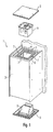
- eine erfindungsgemäße Leuchte, mit zwei Öffnungen und zwei Abdeckungen in Explosionsdarstellung;
- Figur 2
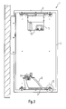
- die in
Figur 1 gezeigte Leuchte im Querschnitt im zusammengebauten Zustand; - Figur 3
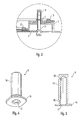
- den in
Figur 2 mit D gekennzeichneten Teil in vergrößerter Darstellung; - Figur 4
- eine Gewindedichtungshülse;
- Figur 5
- die in
Figur 4 gezeigte Gewindedichtungshülse im Querschnitt. - In den
Figuren 1 und2 ist eine erfindungsgemäße Leuchte 1 gezeigt, die ein Gehäuse 2 aufweist, das beispielsweise dazu ausgebildet ist an einer Wand befestigt werden zu können. Bei der in denFiguren 1 und2 gezeigten Leuchte 1 sind in dem Gehäuse 2 zwei Öffnungen 4 vorgesehen, wobei eine davon nach unten und die andere nach oben weist. - Um diese Öffnungen 4 entsprechend verschließen zu können, sind bei der erfindungsgemäßen Leuchte 1 noch Abdeckungen 3 vorgesehen. Die Abdeckungen 3 sind entsprechend den Öffnungen 4 ausgestaltet, wobei die Abdeckungen 3 etwas größer geformt sind, damit sich bei dem Gehäuse 2 bei beiden Öffnungen 4 jeweils ein Bereich 6 ergibt, der sich mit einem Teil der Abdeckungen 3 überlappt, wenn die Abdeckungen 3 an dem Gehäuse 2 befestigt werden.
- In diesem Bereich 6 sind nun mehrere Löcher 7 angeordnet, die zur Befestigung der Abdeckungen 3, die ebenfalls entsprechende Löcher aufweisen, dienen.
- Wie aus der vergrößerten Darstellung in
Figur 3 hervorgeht, werden die Abdeckungen 3 mit Hilfe von Schrauben 5 befestigt. Hierbei ist zusätzlich noch eine Gewindedichtungshülse 8 vorgesehen, die in den Löchern 7 angeordnet ist. - Diese Gewindedichtungshülse 8 ist genauer in den
Figuren 4 und 5 dargestellt. Die Gewindedichtungshülse 8 weist einen länglichen im Wesentlichen zylindrischen Teil 14 auf, in dem ein länglicher Hohlraum 16 angeordnet ist. Der Hohlraum 16 ist dabei innerhalb des zylindrischen Teils 14 derart angeordnet, dass eine nach außen ragende Öffnung 17 des Hohlraums an einem Ende des zylindrischen Teils 14 vorgesehen ist. Dem gegenüber ist der zylindrische Teil 14 an dem anderen Ende verschlossen, wodurch auch der Hohlraum 16 nur einseitig geöffnet ist. Der Hohlraum 16 weist des Weiteren noch ein Innengewinde auf, wodurch es möglich wird, dass über die Öffnung 17 von außen die Schraube 5 in das Innengewinde geschraubt werden kann. - Zusätzlich ist an dem Ende des zylindrischen Teils 14, an dem sich die Öffnung 17 befindet, noch ein um die Öffnung laufender, flanschartiger Rand 15 vorgesehen, der über den zylindrischen Teil 14 seitlich nach außen hinaussteht. In dem Übergangsbereich 18 zwischen dem zylindrischen Teil 14 und dem Rand 15 ist ein etwas schmälerer Umfang im Vergleich zu dem restlichen zylindrischen Teil 14 vorgesehen. Zudem weist dieser Bereich 18 auch kein Außengewinde auf.
- Die Gewindedichtungshülsen 8 werden nun in die Löcher 7 eingesetzt, wobei vorgesehen ist, dass die Löcher 7 als Gewindedurchzüge ausgestaltet sind. Die Gewindedichtungshülsen 8 werden dann mit einem Gewindekleber in die Gewindedurchzüge 7 eingedreht, wodurch nach vollständigem Eindrehen der Gewindedichtungshülsen 8 der Gewindekleber zwischen dem Rand 15 und dem Gehäuse 2 bzw. den Gewindedurchzügen 7 und den Außengewinden der Gewindedichtungshülsen 8 angeordnet ist. Hierdurch ergibt sich eine Dichtigkeit zwischen den jeweiligen Teilen.
- Wie aus
Figur 3 hervorgeht, sind die Gewindedichtungshülsen 8 derart in den Gewindedurchzügen 7 angeordnet, dass der Großteil des zylindrischen Teils 14 der Gewindedichtungshülsen 8 in dem Gehäuse 2 angeordnet ist. Im Gegensatz hierzu liegt der Rand 15 von außen an dem Gehäuse 2 an, wodurch der Rand 15 einen dichtenden Anschlag für den zylindrischen Teil 14 bildet. - Dies wird dadurch erreicht, dass die Gewindedichtungshülsen 8 von außen zuerst mit dem Ende des zylindrischen Teils 14 in die Gewindedurchzüge 7 gedreht werden, das dem Ende gegenüberliegt, an dem der Rand 15 vorgesehen ist. Nachdem dann die Gewindedichtungshülsen 8 mehr oder weniger vollständig in die Gewindedurchzüge 7 eingedreht worden sind, befindet sich dann der Bereich 18 der kein Außengewinde mehr aufweist im Bereich der Gewindedurchzüge 7, wodurch eine leichte Verrastung bzw. Fixierung erfolgt. Zusätzlich kann auch vorgesehen sein, dass in diesem Bereich 18 auch etwas Gewindekleber angeordnet ist.
- Nachdem die Gewindedichtungshülsen 8 vollständig in die Löcher 7 bzw. die Gewindedurchzüge eingedreht sind, werden diese Löcher 7 durch die Gewindedichtungshülsen 8 dichtend abgeschlossen, da wie bereits erläutert die Gewindedichtungshülsen 8 lediglich an einer Seite eine Öffnung aufweisen und zusätzlich der Rand 15 dichtend an dem Gehäuse 2 anliegt.
- Um eine entsprechend abgedichtete Leuchte 1 zu erhalten, die beispielsweise der IP-Schutzklasse 65 entspricht, sind zusätzlich noch Dichtungselemente 13 vorgesehen, die bei befestigter Abdeckung 3 eine Abdichtung zwischen der Abdeckung 3 und dem Gehäuse 2 ermöglichen. Hierfür sind die Dichtungselemente 13 in dem Bereich 6 des Gehäuses 2 angeordnet, der sich mit einem Teil der Abdeckung 3 überlappt. Diese Ausgestaltung ist wiederum in
Figur 3 gezeigt, wobei hier die Abdeckungen 3 an ihren Enden abgewinkelt sind und in entsprechende Vertiefungen des Gehäuses 2 eingreifen. - Denkbar wäre aber auch beispielsweise, dass keine weiteren Dichtungselemente vorgesehen sind, wobei dann bei entsprechender Ausgestaltung der Abdeckungen 3 und des Gehäuses 2 die Funktion der Dichtungselemente durch den Rand 15 der Gewindedichtungshülsen 8 übernommen werden könnte.
- Insgesamt ergibt sich also eine Leuchte, bei der ohne Weiteres die Abdeckungen 3 entfernt und wieder angebracht werden können, wobei lediglich die Schrauben 5 betätigt werden müssen. Bei der in den
Figuren 1 und2 gezeigten Leuchte 1 ist dementsprechend an bzw. auf den Abdeckplatten 3 eine Leuchteneinheit bzw. ein Geräteträger 11 vorgesehen, wobei die Leuchteneinheit einen Reflektor 9 und ein Leuchtmittel 10 umfasst und auf dem Geräteträger 11 ein Lampenbetriebsgerät 12 befestigt ist. Für einen Leuchtmittelwechsel ist es dementsprechend nun lediglich erforderlich, dass die Abdeckung 3 entsprechend entfernt wird, wobei dann der Reflektor 9 bzw. das Leuchtmittel 10 leicht zugänglich ist. Auch ein Austausch bzw. eine Reparatur des Lampenbetriebsgeräts 12 ist entsprechend einfach möglich. Zugleich ist es bei der erfindungsgemäßen Leuchte 1 aber auch gewährleistet, dass der Innenraum entsprechend abgedichtet ist, wodurch eine gewünschte IP-Schutzklasse erreicht und auch nach mehrmaligem Demontieren der Abdeckplatten 3 gewährleistet werden kann. - Anstelle der Montage der Leuchteneinheit und des Geräteträgers 11 auf den Abdeckungen 3 wäre es aber auch vorstellbar, dass diese Teile innerhalb des Gehäuses 2 angeordnet sind, wobei dann durch die leichte Demontierbarkeit der Abdeckungen 3 eine leichte Zugänglichkeit zu diesen Teilen gewährleistet ist.
- Um eine entsprechende Lichtabgabe des Leuchtmittels 10 in Verbindung mit dem Reflektor 9 zu ermöglichen, kann des Weiteren vorgesehen sein, dass die Abdeckung 3 an der die Leuchteneinheit vorgesehen ist, transparent bzw. lichtbeeinflussend ausgestaltet ist. Zusätzlich könnte auch vorgesehen sein, dass der Reflektor mit einer Glasscheibe abgeschlossen wird.
Claims (14)
- Leuchte (1) aufweisend● ein Gehäuse (2) mit mindestens einer Öffnung (4) und● eine Abdeckung (3) zum Verschließen der Öffnung (4),wobei die Abdeckung (3) mit mindestens einer Schraube (5) an dem Gehäuse (2) befestigt werden kann und das Gehäuse (2) mindestens einen Bereich (6) aufweist, der sich mit einem Teil der Abdeckung (3) im befestigten Zustand überlappt,
dadurch gekennzeichnet,
dass das Gehäuse (2) in dem Bereich (6), der sich mit einem Teil der Abdeckung (3) überlappt, mindestens ein Loch (7) aufweist, in dem eine Gewindedichtungshülse (8) angeordnet ist, wobei die Schraube (5) zur Befestigung der Abdeckung (3) in die Gewindedichtungshülse (8) geschraubt werden kann. - Leuchte nach Anspruch 1,
dadurch gekennzeichnet,
dass die Gewindedichtungshülse (8) dichtend an dem Gehäuse (2) angeordnet ist. - Leuchte nach einem der Ansprüche 1-2,
dadurch gekennzeichnet,
dass mindestens ein Dichtungselement (13) in dem Bereich (6) des Gehäuses (2) angeordnet ist, der sich mit einem Teil der Abdeckung (3) überlappt. - Leuchte nach einem der Ansprüche 1-3,
dadurch gekennzeichnet,
dass die Gewindedichtungshülse (8) aus einem länglichen im Wesentlichen zylindrischen Teil (14) mit einem länglichen Hohlraum (16) besteht, wobei der Hohlraum (16) ein Innengewinde und an einem Ende des zylindrischen Teils (14) eine Öffnung (17) aufweist, derart, dass über die Öffnung (17) von außen die Schraube (5) in das Innengewinde geschraubt werden kann und wobei der zylindrische Teil (14) der Gewindedichtungshülse (8) durch das Loch (7) des Gehäuses (2) hindurch ragt. - Leuchte nach Anspruch 4,
dadurch gekennzeichnet,
dass die Gewindedichtungshülse (8) an dem Ende des zylindrischen Teils (14) an dem die Öffnung (17) des Hohlraums (16) angeordnet ist einen um die Öffnung (17) laufenden Rand (15) aufweist, der über den zylindrischen Teil (14) seitlich nach außen hinaus steht, wobei der Rand (15) an dem Bereich (6) des Gehäuse (2), der sich mit einem Teil der Abdeckung (3) überlappt, anliegt, derart, dass der Rand (15) einen dichtenden Anschlag für den zylindrischen Teil (14) bildet. - Leuchte nach einem der Ansprüche 4-5,
dadurch gekennzeichnet,
dass der zylindrische Teil (14) der Gewindedichtungshülse (8) ein Außengewinde aufweist und das Loch des Gehäuses (2) als Gewindedurchzug (7) ausgebildet ist. - Leuchte nach Anspruch 5 und 6,
dadurch gekennzeichnet,
dass der zylindrische Teil (14) der Gewindedichtungshülse (8) in dem Bereich (18) der im Anschluss an den Rand (15) folgt im Umfang schmäler als der restliche zylindrische Teil ist und kein Außengewinde aufweist. - Leuchte nach einem der Ansprüche 6-7,
dadurch gekennzeichnet,
dass zwischen dem Rand (15) der Gewindedichtungshülse (8) und dem Gehäuse (2) und/oder zwischen dem Außengewinde der Gewindedichtungshülse (8) und dem Gewindedurchzug (7) des Gehäuses (2) ein Gewindekleber angeordnet ist. - Leuchte nach einem der vorherigen Ansprüche,
dadurch gekennzeichnet,
dass die Abdeckung (3) transparent ausgestaltet ist. - Leuchte nach einem der vorherigen Ansprüche,
dadurch gekennzeichnet,
dass die Abdeckung (3) lichtbeeinflussende Eigenschaften aufweist. - Leuchte nach einem der vorherigen Ansprüche,
dadurch gekennzeichnet,
dass an der Abdeckung (3) eine Leuchteneinheit oder ein Geräteträger (11) angeordnet ist, welche/r sich bei an dem Gehäuse (2) befestigter Abdeckung (3) innerhalb des Gehäuses (2) befindet. - Leuchte nach einem der Ansprüche 1-10,
dadurch gekennzeichnet,
dass innerhalb des Gehäuses (2) in der Nähe der Öffnung (4) eine Leuchteneinheit oder ein Geräteträger (11) angeordnet ist. - Leuchte nach einem der Ansprüche 11-12,
dadurch gekennzeichnet,
dass die Leuchteneinheit ein Leuchtmittel (10) und einen Reflektor (9) umfasst. - Leuchte nach einem der Ansprüche 11-12,
dadurch gekennzeichnet,
dass auf dem Geräteträger (11) ein Lampenbetriebsgerät (12) befestigt ist.
Applications Claiming Priority (1)
| Application Number | Priority Date | Filing Date | Title |
|---|---|---|---|
| DE202011000994.7U DE202011000994U1 (de) | 2011-04-28 | 2011-04-28 | Leuchte |
Publications (3)
| Publication Number | Publication Date |
|---|---|
| EP2518399A2 true EP2518399A2 (de) | 2012-10-31 |
| EP2518399A3 EP2518399A3 (de) | 2013-03-13 |
| EP2518399B1 EP2518399B1 (de) | 2014-10-15 |
Family
ID=46045834
Family Applications (1)
| Application Number | Title | Priority Date | Filing Date |
|---|---|---|---|
| EP20120165453 Not-in-force EP2518399B1 (de) | 2011-04-28 | 2012-04-25 | Leuchte |
Country Status (2)
| Country | Link |
|---|---|
| EP (1) | EP2518399B1 (de) |
| DE (1) | DE202011000994U1 (de) |
Family Cites Families (9)
| Publication number | Priority date | Publication date | Assignee | Title |
|---|---|---|---|---|
| GB1428723A (en) * | 1973-07-19 | 1976-03-17 | Psm Fasteners Ltd | Rivet bushes |
| DE8030264U1 (de) * | 1980-11-13 | 1981-03-12 | Herbert Waldmann Gmbh & Co, 7220 Schwenningen | Staubdichte und strahlwassergeschuetzte leuchte |
| GB2148113A (en) * | 1983-09-02 | 1985-05-30 | Unilec Lighting Limited | Flameproof enclosure |
| DD263105A1 (de) * | 1987-07-27 | 1988-12-21 | Peossnecker Aussenleuchten Veb | Spritzwassergeschuetzte strahlerleuchte |
| DE4447312A1 (de) * | 1994-12-31 | 1996-07-11 | Manfred Gaertner | Vorrichtung zur Befestigung eines Glaskörpers |
| DE19856958C1 (de) * | 1998-12-10 | 2000-06-08 | Maehler & Kaege Ag | Leuchtengehäuse |
| DE102004009632A1 (de) * | 2004-02-27 | 2005-09-15 | Zumtobel Staff Gmbh & Co. Kg | Bodeneinbauleuchte |
| JP2006322506A (ja) * | 2005-05-18 | 2006-11-30 | Seiwa Electric Mfg Co Ltd | 部品取付構造 |
| DE102005048907A1 (de) * | 2005-10-10 | 2007-04-26 | Siemens Ag | Unterflur-Blitzfeuer |
-
2011
- 2011-04-28 DE DE202011000994.7U patent/DE202011000994U1/de not_active Expired - Lifetime
-
2012
- 2012-04-25 EP EP20120165453 patent/EP2518399B1/de not_active Not-in-force
Non-Patent Citations (1)
| Title |
|---|
| None |
Also Published As
| Publication number | Publication date |
|---|---|
| EP2518399B1 (de) | 2014-10-15 |
| EP2518399A3 (de) | 2013-03-13 |
| DE202011000994U1 (de) | 2014-08-25 |
Similar Documents
| Publication | Publication Date | Title |
|---|---|---|
| EP2264358B1 (de) | Leuchte und Lichtband | |
| DE102013101120A1 (de) | Kabelfixierung | |
| EP2840203A1 (de) | Tür- oder Fensterbeschlag mit mehrteiliger Abdeckblende | |
| DE19854669C2 (de) | Signaleinrichtung | |
| EP2518399B1 (de) | Leuchte | |
| DE102008060843B3 (de) | Umlenkvorrichtung für Kabel | |
| EP3763901B1 (de) | Türschliesssystem | |
| EP2941803B1 (de) | Vorrichtung zum verspannen von gegenständen | |
| DE202013101823U1 (de) | Plattenförmiges Reflektorelement für LED-Platine | |
| EP4460643B1 (de) | Baugruppe mit bajonettverschluss | |
| DE10134795B4 (de) | Leuchte | |
| EP2957814A1 (de) | Beleuchtungsanordnung | |
| DE102013107634A1 (de) | Spindelsperre für Jalousien | |
| DE102017128816A1 (de) | Explosionsgeschütztes Gehäuse | |
| DE102019209382A1 (de) | Gehäuse für einen Antrieb und Antrieb | |
| DE10301879B3 (de) | Steckvorrichtungselement mit Montagegewinde | |
| DE20010707U1 (de) | Leuchte | |
| DE202010003097U1 (de) | Einsteckschloss und Stulpkörper zur Verwendung bei derartigen Einsteckschlössern | |
| DE202017101752U1 (de) | Leuchte mit verstellbarem Lichtkopf | |
| DE202010001441U1 (de) | Justiersystem für Bauelemente | |
| EP3356726A1 (de) | Haltevorrichtung mit tragschiene und halteelement für die tragschiene | |
| DE202006009812U1 (de) | Leuchte mit Explosions-Schutz | |
| DE202014007771U1 (de) | Leuchte | |
| DE10214300A1 (de) | Kabeldurchführungsleiste | |
| EP2711622A2 (de) | Leuchte mit Berührschutz |
Legal Events
| Date | Code | Title | Description |
|---|---|---|---|
| PUAI | Public reference made under article 153(3) epc to a published international application that has entered the european phase |
Free format text: ORIGINAL CODE: 0009012 |
|
| AK | Designated contracting states |
Kind code of ref document: A2 Designated state(s): AL AT BE BG CH CY CZ DE DK EE ES FI FR GB GR HR HU IE IS IT LI LT LU LV MC MK MT NL NO PL PT RO RS SE SI SK SM TR |
|
| AX | Request for extension of the european patent |
Extension state: BA ME |
|
| PUAL | Search report despatched |
Free format text: ORIGINAL CODE: 0009013 |
|
| AK | Designated contracting states |
Kind code of ref document: A3 Designated state(s): AL AT BE BG CH CY CZ DE DK EE ES FI FR GB GR HR HU IE IS IT LI LT LU LV MC MK MT NL NO PL PT RO RS SE SI SK SM TR |
|
| AX | Request for extension of the european patent |
Extension state: BA ME |
|
| RIC1 | Information provided on ipc code assigned before grant |
Ipc: F21V 17/12 20060101AFI20130207BHEP Ipc: F21W 131/10 20060101ALN20130207BHEP Ipc: F21V 31/00 20060101ALI20130207BHEP |
|
| 17P | Request for examination filed |
Effective date: 20130821 |
|
| RBV | Designated contracting states (corrected) |
Designated state(s): AL AT BE BG CH CY CZ DE DK EE ES FI FR GB GR HR HU IE IS IT LI LT LU LV MC MK MT NL NO PL PT RO RS SE SI SK SM TR |
|
| 17Q | First examination report despatched |
Effective date: 20131107 |
|
| RIC1 | Information provided on ipc code assigned before grant |
Ipc: F21V 31/00 20060101ALI20140410BHEP Ipc: F21V 17/12 20060101AFI20140410BHEP Ipc: F21W 131/10 20060101ALN20140410BHEP |
|
| GRAP | Despatch of communication of intention to grant a patent |
Free format text: ORIGINAL CODE: EPIDOSNIGR1 |
|
| INTG | Intention to grant announced |
Effective date: 20140526 |
|
| GRAS | Grant fee paid |
Free format text: ORIGINAL CODE: EPIDOSNIGR3 |
|
| GRAA | (expected) grant |
Free format text: ORIGINAL CODE: 0009210 |
|
| AK | Designated contracting states |
Kind code of ref document: B1 Designated state(s): AL AT BE BG CH CY CZ DE DK EE ES FI FR GB GR HR HU IE IS IT LI LT LU LV MC MK MT NL NO PL PT RO RS SE SI SK SM TR |
|
| REG | Reference to a national code |
Ref country code: CH Ref legal event code: EP Ref country code: GB Ref legal event code: FG4D Free format text: NOT ENGLISH Ref country code: CH Ref legal event code: NV Representative=s name: FIAMMENGHI-FIAMMENGHI, CH |
|
| REG | Reference to a national code |
Ref country code: IE Ref legal event code: FG4D Free format text: LANGUAGE OF EP DOCUMENT: GERMAN |
|
| REG | Reference to a national code |
Ref country code: AT Ref legal event code: REF Ref document number: 691860 Country of ref document: AT Kind code of ref document: T Effective date: 20141115 |
|
| REG | Reference to a national code |
Ref country code: DE Ref legal event code: R096 Ref document number: 502012001420 Country of ref document: DE Effective date: 20141127 |
|
| REG | Reference to a national code |
Ref country code: NL Ref legal event code: VDEP Effective date: 20141015 |
|
| REG | Reference to a national code |
Ref country code: LT Ref legal event code: MG4D |
|
| PG25 | Lapsed in a contracting state [announced via postgrant information from national office to epo] |
Ref country code: NL Free format text: LAPSE BECAUSE OF FAILURE TO SUBMIT A TRANSLATION OF THE DESCRIPTION OR TO PAY THE FEE WITHIN THE PRESCRIBED TIME-LIMIT Effective date: 20141015 |
|
| PG25 | Lapsed in a contracting state [announced via postgrant information from national office to epo] |
Ref country code: PT Free format text: LAPSE BECAUSE OF FAILURE TO SUBMIT A TRANSLATION OF THE DESCRIPTION OR TO PAY THE FEE WITHIN THE PRESCRIBED TIME-LIMIT Effective date: 20150216 Ref country code: FI Free format text: LAPSE BECAUSE OF FAILURE TO SUBMIT A TRANSLATION OF THE DESCRIPTION OR TO PAY THE FEE WITHIN THE PRESCRIBED TIME-LIMIT Effective date: 20141015 Ref country code: ES Free format text: LAPSE BECAUSE OF FAILURE TO SUBMIT A TRANSLATION OF THE DESCRIPTION OR TO PAY THE FEE WITHIN THE PRESCRIBED TIME-LIMIT Effective date: 20141015 Ref country code: NO Free format text: LAPSE BECAUSE OF FAILURE TO SUBMIT A TRANSLATION OF THE DESCRIPTION OR TO PAY THE FEE WITHIN THE PRESCRIBED TIME-LIMIT Effective date: 20150115 Ref country code: LT Free format text: LAPSE BECAUSE OF FAILURE TO SUBMIT A TRANSLATION OF THE DESCRIPTION OR TO PAY THE FEE WITHIN THE PRESCRIBED TIME-LIMIT Effective date: 20141015 Ref country code: IS Free format text: LAPSE BECAUSE OF FAILURE TO SUBMIT A TRANSLATION OF THE DESCRIPTION OR TO PAY THE FEE WITHIN THE PRESCRIBED TIME-LIMIT Effective date: 20150215 |
|
| PG25 | Lapsed in a contracting state [announced via postgrant information from national office to epo] |
Ref country code: GR Free format text: LAPSE BECAUSE OF FAILURE TO SUBMIT A TRANSLATION OF THE DESCRIPTION OR TO PAY THE FEE WITHIN THE PRESCRIBED TIME-LIMIT Effective date: 20150116 Ref country code: PL Free format text: LAPSE BECAUSE OF FAILURE TO SUBMIT A TRANSLATION OF THE DESCRIPTION OR TO PAY THE FEE WITHIN THE PRESCRIBED TIME-LIMIT Effective date: 20141015 Ref country code: RS Free format text: LAPSE BECAUSE OF FAILURE TO SUBMIT A TRANSLATION OF THE DESCRIPTION OR TO PAY THE FEE WITHIN THE PRESCRIBED TIME-LIMIT Effective date: 20141015 Ref country code: SE Free format text: LAPSE BECAUSE OF FAILURE TO SUBMIT A TRANSLATION OF THE DESCRIPTION OR TO PAY THE FEE WITHIN THE PRESCRIBED TIME-LIMIT Effective date: 20141015 Ref country code: CY Free format text: LAPSE BECAUSE OF FAILURE TO SUBMIT A TRANSLATION OF THE DESCRIPTION OR TO PAY THE FEE WITHIN THE PRESCRIBED TIME-LIMIT Effective date: 20141015 Ref country code: HR Free format text: LAPSE BECAUSE OF FAILURE TO SUBMIT A TRANSLATION OF THE DESCRIPTION OR TO PAY THE FEE WITHIN THE PRESCRIBED TIME-LIMIT Effective date: 20141015 Ref country code: LV Free format text: LAPSE BECAUSE OF FAILURE TO SUBMIT A TRANSLATION OF THE DESCRIPTION OR TO PAY THE FEE WITHIN THE PRESCRIBED TIME-LIMIT Effective date: 20141015 |
|
| REG | Reference to a national code |
Ref country code: DE Ref legal event code: R097 Ref document number: 502012001420 Country of ref document: DE |
|
| PG25 | Lapsed in a contracting state [announced via postgrant information from national office to epo] |
Ref country code: SK Free format text: LAPSE BECAUSE OF FAILURE TO SUBMIT A TRANSLATION OF THE DESCRIPTION OR TO PAY THE FEE WITHIN THE PRESCRIBED TIME-LIMIT Effective date: 20141015 Ref country code: RO Free format text: LAPSE BECAUSE OF FAILURE TO SUBMIT A TRANSLATION OF THE DESCRIPTION OR TO PAY THE FEE WITHIN THE PRESCRIBED TIME-LIMIT Effective date: 20141015 Ref country code: EE Free format text: LAPSE BECAUSE OF FAILURE TO SUBMIT A TRANSLATION OF THE DESCRIPTION OR TO PAY THE FEE WITHIN THE PRESCRIBED TIME-LIMIT Effective date: 20141015 Ref country code: CZ Free format text: LAPSE BECAUSE OF FAILURE TO SUBMIT A TRANSLATION OF THE DESCRIPTION OR TO PAY THE FEE WITHIN THE PRESCRIBED TIME-LIMIT Effective date: 20141015 Ref country code: DK Free format text: LAPSE BECAUSE OF FAILURE TO SUBMIT A TRANSLATION OF THE DESCRIPTION OR TO PAY THE FEE WITHIN THE PRESCRIBED TIME-LIMIT Effective date: 20141015 |
|
| PLBE | No opposition filed within time limit |
Free format text: ORIGINAL CODE: 0009261 |
|
| STAA | Information on the status of an ep patent application or granted ep patent |
Free format text: STATUS: NO OPPOSITION FILED WITHIN TIME LIMIT |
|
| PG25 | Lapsed in a contracting state [announced via postgrant information from national office to epo] |
Ref country code: IT Free format text: LAPSE BECAUSE OF FAILURE TO SUBMIT A TRANSLATION OF THE DESCRIPTION OR TO PAY THE FEE WITHIN THE PRESCRIBED TIME-LIMIT Effective date: 20141015 |
|
| 26N | No opposition filed |
Effective date: 20150716 |
|
| PG25 | Lapsed in a contracting state [announced via postgrant information from national office to epo] |
Ref country code: MC Free format text: LAPSE BECAUSE OF FAILURE TO SUBMIT A TRANSLATION OF THE DESCRIPTION OR TO PAY THE FEE WITHIN THE PRESCRIBED TIME-LIMIT Effective date: 20141015 Ref country code: LU Free format text: LAPSE BECAUSE OF FAILURE TO SUBMIT A TRANSLATION OF THE DESCRIPTION OR TO PAY THE FEE WITHIN THE PRESCRIBED TIME-LIMIT Effective date: 20150425 |
|
| REG | Reference to a national code |
Ref country code: IE Ref legal event code: MM4A |
|
| PG25 | Lapsed in a contracting state [announced via postgrant information from national office to epo] |
Ref country code: SI Free format text: LAPSE BECAUSE OF FAILURE TO SUBMIT A TRANSLATION OF THE DESCRIPTION OR TO PAY THE FEE WITHIN THE PRESCRIBED TIME-LIMIT Effective date: 20141015 |
|
| REG | Reference to a national code |
Ref country code: FR Ref legal event code: PLFP Year of fee payment: 5 |
|
| PG25 | Lapsed in a contracting state [announced via postgrant information from national office to epo] |
Ref country code: IE Free format text: LAPSE BECAUSE OF NON-PAYMENT OF DUE FEES Effective date: 20150425 |
|
| PG25 | Lapsed in a contracting state [announced via postgrant information from national office to epo] |
Ref country code: MT Free format text: LAPSE BECAUSE OF FAILURE TO SUBMIT A TRANSLATION OF THE DESCRIPTION OR TO PAY THE FEE WITHIN THE PRESCRIBED TIME-LIMIT Effective date: 20141015 |
|
| REG | Reference to a national code |
Ref country code: FR Ref legal event code: PLFP Year of fee payment: 6 |
|
| PG25 | Lapsed in a contracting state [announced via postgrant information from national office to epo] |
Ref country code: BG Free format text: LAPSE BECAUSE OF FAILURE TO SUBMIT A TRANSLATION OF THE DESCRIPTION OR TO PAY THE FEE WITHIN THE PRESCRIBED TIME-LIMIT Effective date: 20141015 Ref country code: HU Free format text: LAPSE BECAUSE OF FAILURE TO SUBMIT A TRANSLATION OF THE DESCRIPTION OR TO PAY THE FEE WITHIN THE PRESCRIBED TIME-LIMIT; INVALID AB INITIO Effective date: 20120425 Ref country code: SM Free format text: LAPSE BECAUSE OF FAILURE TO SUBMIT A TRANSLATION OF THE DESCRIPTION OR TO PAY THE FEE WITHIN THE PRESCRIBED TIME-LIMIT Effective date: 20141015 |
|
| PG25 | Lapsed in a contracting state [announced via postgrant information from national office to epo] |
Ref country code: BE Free format text: LAPSE BECAUSE OF NON-PAYMENT OF DUE FEES Effective date: 20150430 |
|
| PGFP | Annual fee paid to national office [announced via postgrant information from national office to epo] |
Ref country code: GB Payment date: 20170427 Year of fee payment: 6 Ref country code: FR Payment date: 20170428 Year of fee payment: 6 Ref country code: CH Payment date: 20170426 Year of fee payment: 6 |
|
| PG25 | Lapsed in a contracting state [announced via postgrant information from national office to epo] |
Ref country code: TR Free format text: LAPSE BECAUSE OF FAILURE TO SUBMIT A TRANSLATION OF THE DESCRIPTION OR TO PAY THE FEE WITHIN THE PRESCRIBED TIME-LIMIT Effective date: 20141015 |
|
| PGFP | Annual fee paid to national office [announced via postgrant information from national office to epo] |
Ref country code: AT Payment date: 20170428 Year of fee payment: 6 |
|
| PG25 | Lapsed in a contracting state [announced via postgrant information from national office to epo] |
Ref country code: MK Free format text: LAPSE BECAUSE OF FAILURE TO SUBMIT A TRANSLATION OF THE DESCRIPTION OR TO PAY THE FEE WITHIN THE PRESCRIBED TIME-LIMIT Effective date: 20141015 |
|
| PG25 | Lapsed in a contracting state [announced via postgrant information from national office to epo] |
Ref country code: AL Free format text: LAPSE BECAUSE OF FAILURE TO SUBMIT A TRANSLATION OF THE DESCRIPTION OR TO PAY THE FEE WITHIN THE PRESCRIBED TIME-LIMIT Effective date: 20141015 |
|
| REG | Reference to a national code |
Ref country code: CH Ref legal event code: PL |
|
| REG | Reference to a national code |
Ref country code: AT Ref legal event code: MM01 Ref document number: 691860 Country of ref document: AT Kind code of ref document: T Effective date: 20180425 |
|
| GBPC | Gb: european patent ceased through non-payment of renewal fee |
Effective date: 20180425 |
|
| REG | Reference to a national code |
Ref country code: DE Ref legal event code: R084 Ref document number: 502012001420 Country of ref document: DE |
|
| PG25 | Lapsed in a contracting state [announced via postgrant information from national office to epo] |
Ref country code: AT Free format text: LAPSE BECAUSE OF NON-PAYMENT OF DUE FEES Effective date: 20180425 |
|
| PG25 | Lapsed in a contracting state [announced via postgrant information from national office to epo] |
Ref country code: CH Free format text: LAPSE BECAUSE OF NON-PAYMENT OF DUE FEES Effective date: 20180430 Ref country code: GB Free format text: LAPSE BECAUSE OF NON-PAYMENT OF DUE FEES Effective date: 20180425 Ref country code: LI Free format text: LAPSE BECAUSE OF NON-PAYMENT OF DUE FEES Effective date: 20180430 |
|
| PG25 | Lapsed in a contracting state [announced via postgrant information from national office to epo] |
Ref country code: FR Free format text: LAPSE BECAUSE OF NON-PAYMENT OF DUE FEES Effective date: 20180430 |
|
| P01 | Opt-out of the competence of the unified patent court (upc) registered |
Effective date: 20230530 |
|
| PGFP | Annual fee paid to national office [announced via postgrant information from national office to epo] |
Ref country code: DE Payment date: 20230427 Year of fee payment: 12 |
|
| REG | Reference to a national code |
Ref country code: DE Ref legal event code: R119 Ref document number: 502012001420 Country of ref document: DE |
|
| PG25 | Lapsed in a contracting state [announced via postgrant information from national office to epo] |
Ref country code: DE Free format text: LAPSE BECAUSE OF NON-PAYMENT OF DUE FEES Effective date: 20241105 |
|
| PG25 | Lapsed in a contracting state [announced via postgrant information from national office to epo] |
Ref country code: DE Free format text: LAPSE BECAUSE OF NON-PAYMENT OF DUE FEES Effective date: 20241105 |