EP2518198B1 - Knitting method of tubular knitted fabric, and tubular knitted fabric - Google Patents
Knitting method of tubular knitted fabric, and tubular knitted fabric Download PDFInfo
- Publication number
- EP2518198B1 EP2518198B1 EP12002909.5A EP12002909A EP2518198B1 EP 2518198 B1 EP2518198 B1 EP 2518198B1 EP 12002909 A EP12002909 A EP 12002909A EP 2518198 B1 EP2518198 B1 EP 2518198B1
- Authority
- EP
- European Patent Office
- Prior art keywords
- knitting
- base surface
- knitted fabric
- needle
- main body
- Prior art date
- Legal status (The legal status is an assumption and is not a legal conclusion. Google has not performed a legal analysis and makes no representation as to the accuracy of the status listed.)
- Active
Links
Images


Classifications
-
- D—TEXTILES; PAPER
- D04—BRAIDING; LACE-MAKING; KNITTING; TRIMMINGS; NON-WOVEN FABRICS
- D04B—KNITTING
- D04B7/00—Flat-bed knitting machines with independently-movable needles
- D04B7/30—Flat-bed knitting machines with independently-movable needles specially adapted for knitting goods of particular configuration
- D04B7/32—Flat-bed knitting machines with independently-movable needles specially adapted for knitting goods of particular configuration tubular goods
-
- D—TEXTILES; PAPER
- D04—BRAIDING; LACE-MAKING; KNITTING; TRIMMINGS; NON-WOVEN FABRICS
- D04B—KNITTING
- D04B1/00—Weft knitting processes for the production of fabrics or articles not dependent on the use of particular machines; Fabrics or articles defined by such processes
- D04B1/22—Weft knitting processes for the production of fabrics or articles not dependent on the use of particular machines; Fabrics or articles defined by such processes specially adapted for knitting goods of particular configuration
-
- D—TEXTILES; PAPER
- D04—BRAIDING; LACE-MAKING; KNITTING; TRIMMINGS; NON-WOVEN FABRICS
- D04B—KNITTING
- D04B1/00—Weft knitting processes for the production of fabrics or articles not dependent on the use of particular machines; Fabrics or articles defined by such processes
- D04B1/10—Patterned fabrics or articles
- D04B1/102—Patterned fabrics or articles with stitch pattern
- D04B1/108—Gussets, e.g. pouches or heel or toe portions
-
- D—TEXTILES; PAPER
- D04—BRAIDING; LACE-MAKING; KNITTING; TRIMMINGS; NON-WOVEN FABRICS
- D04B—KNITTING
- D04B1/00—Weft knitting processes for the production of fabrics or articles not dependent on the use of particular machines; Fabrics or articles defined by such processes
- D04B1/22—Weft knitting processes for the production of fabrics or articles not dependent on the use of particular machines; Fabrics or articles defined by such processes specially adapted for knitting goods of particular configuration
- D04B1/24—Weft knitting processes for the production of fabrics or articles not dependent on the use of particular machines; Fabrics or articles defined by such processes specially adapted for knitting goods of particular configuration wearing apparel
- D04B1/26—Weft knitting processes for the production of fabrics or articles not dependent on the use of particular machines; Fabrics or articles defined by such processes specially adapted for knitting goods of particular configuration wearing apparel stockings
-
- D—TEXTILES; PAPER
- D10—INDEXING SCHEME ASSOCIATED WITH SUBLASSES OF SECTION D, RELATING TO TEXTILES
- D10B—INDEXING SCHEME ASSOCIATED WITH SUBLASSES OF SECTION D, RELATING TO TEXTILES
- D10B2403/00—Details of fabric structure established in the fabric forming process
- D10B2403/03—Shape features
- D10B2403/033—Three dimensional fabric, e.g. forming or comprising cavities in or protrusions from the basic planar configuration, or deviations from the cylindrical shape as generally imposed by the fabric forming process
- D10B2403/0332—Three dimensional fabric, e.g. forming or comprising cavities in or protrusions from the basic planar configuration, or deviations from the cylindrical shape as generally imposed by the fabric forming process with gussets folding into three dimensional shape, e.g. seat covers
-
- D—TEXTILES; PAPER
- D10—INDEXING SCHEME ASSOCIATED WITH SUBLASSES OF SECTION D, RELATING TO TEXTILES
- D10B—INDEXING SCHEME ASSOCIATED WITH SUBLASSES OF SECTION D, RELATING TO TEXTILES
- D10B2501/00—Wearing apparel
- D10B2501/06—Details of garments
- D10B2501/061—Piped openings (pockets)
Definitions
- the present invention relates to a knitting method of a tubular knitted fabric for knitting a seamless tubular knitted fabric including a main body section knitted to a tubular shape and a partitioning section formed inside the main body section, and a tubular knitted fabric obtained by such a knitting method.
- a sock (tubular knitted fabric) having a plurality of tubular toe portions is widely hitting the market in recent years.
- Proposal has been made to form a partitioning section inside a toe portion of the sock.
- a knitting method of starting the knitting of the sock to a tubular shape from a top portion, and forming the partitioning section inside a tube held on a needle bed at the start of the knitting of the toe portion is required.
- Patent Document 1 discloses a knitting method of forming the partitioning section in a traversable manner.
- Patent Document 1 Japanese Unexamined Patent Publication No. 2007-113150
- the partitioning section cannot be formed to the distal end of the toe portion of the sock. This is because the partitioning section cannot be satisfactorily coupled to the toe portion when closing the toe portion and completing the sock.
- the sock in which the partitioning section is not formed to the distal end of the toe portion is worn, the ends of the adjoining toes touch each other. Some people feel this unpleasant, and hence improvement is desired.
- the inventors of the present invention have changed the way of thinking in the process of variously reviewing the above mentioned problem and solved the problem by setting up the tubular knitted fabric from a distal end of the closed side.
- a knitting method of a tubular knitted fabric of the present invention and a tubular knitted fabric knitted with the knitting method will be described.
- a knitting method of a tubular knitted fabric of the present invention is a knitting method of a tubular knitted fabric for knitting, in a seamless manner, a tubular knitted fabric including a main body section, which is knitted to a tubular shape, and a partitioning section, which is formed inside a tube of the main body section to partition the inside of the tube, using a flat knitting machine having at least a front needle bed and a back needle bed, a stitch held on a knitting needle of the needle beds being transferrable to another knitting needle; the knitting method of the tubular knitted fabric including the following steps. (Step ⁇ ) a step of forming a plurality of stitches on the front and back needle beds, and forming a first setup portion comprising the stitches.
- Step ⁇ a step of forming a base surface in which outer peripheral sides are all held on the front and back needle beds with the first setup portion as a starting line, and forming a second setup portion comprising a plurality of pick up stitches connecting to a plane of the base surface.
- Step ⁇ a step of knitting the partitioning section following the second setup portion while knitting the main body section following the outer peripheral sides of the base surface.
- the formation of the base surface in the step P is carried out by repeating knitting of a base surface stitch row, moving the base surface stitch row to one side in a knitting width direction, and forming a pick up stitch on a knitting needle, which became an empty needle by the movement, and on an empty needle substantially facing an end in a moving direction of the moved base surface stitch row.
- the formation of the second setup portion in the step ⁇ is carried out by forming at least one pick up stitch on an empty needle within a knitting width of the base surface stitch row in the middle of knitting of the base surface stitch row.
- two or more second setup portions may be formed in the step ⁇ .
- a plurality of partitioning sections are formed inside the sock to form toe inserting sections for inserting respective toes of a wearer.
- the knitting of the base surface stitch row in the step ⁇ is preferably carried out with either of the front or back needle bed.
- the first setup portion formed in the step ⁇ can be divided to a portion held on the front needle bed and a portion held on the back needle bed.
- the base surface stitch row may be increased in the wale direction only on one needle bed so that the formed state of the stitches configuring the entire base surface is aligned.
- the base surface may be formed by increasing the base surface stitch row in the wale direction on the front needle bed and increasing the base surface stitch row in the wale direction also on the back needle bed.
- a tubular knitted fabric of the present invention is a tubular knitted fabric, including a main body section, which is knitted to a tubular shape, and a partitioning section, which is formed inside a tube of the main body section to partition the inside of the tube, the tubular knitted fabric being knitted in a seamless manner using a flat knitting machine having at least a front needle bed and a back needle bed, a stitch held on a knitting needle of the needle beds being transferrable to another knitting needle.
- the tubular knitted fabric of the present invention includes a base surface for enabling a distal end portion of the main body section to be three-dimensional, where the partitioning section is set out from a plane on an interior side of the main body section of the base surface.
- a second setup portion comprises a plurality of pick up stitches connecting to a plane of the base surface.
- a tubular knitted fabric of the present invention including a base surface and a tubular main body section set out from outer peripheral sides of the base surface, the tubular knitted fabric of the present invention including a partitioning section set out from a plane of the base surface can be knitted.
- the tubular knitted fabric of the present invention include a sock, a bag, and the like.
- a sock in which a partitioning section is formed inside a tube of the sock and in which the partitioning section reaches up to a portion on the most distal end of the toe portion of the sock can be knitted.
- This sock prevents contact between the toes when worn, and thus is very comfortable to wear.
- a knitting example using a two-bed flat knitting machine having a front and a back needle bed extending in a transverse direction and disposed opposite to each other in a cross direction, stitches capable of being transferred between the front and back needle beds.
- the flat knitting machine to use may, of course, be a flat knitting machine having a transfer dedicated bed, a flat knitting machine including knitting needles for temporarily holding stitches, or a four-bed flat knitting machine, where the knitting of the present embodiment can be more efficiently carried out by using them.
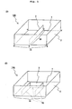
- a tubular knitted fabric 100 of the present embodiment shown in Fig. 1A includes a main body section 2 knitted to a tubular shape, a planar base surface 1 for closing one end side (lower side in plane of drawing) of the main body section 2, and a partitioning section 3 formed inside the main body section 2 to connect an inner peripheral surface of the main body section 2 and the base surface 1.
- the other end side (upper side in plane of drawing) of the main body section 2 is opened, and the partitioning section 3 is formed up to the middle in the axial direction of the main body section 2.
- the most characteristic feature of the tubular knitted fabric 100 of the present embodiment is that the shape on the one end side of the main body section 2 is closed in a form of matching the shape of the outer peripheral side of the planar base surface 1, so that the main body section 2 has a three-dimensional shape and that the partitioning section 3 formed inside the main body section 2 is set up from the base surface 1.
- a first setup portion 1A (position of side ab) for knitting the base surface 1 is first formed, and the base surface 1 is knitted with the first setup portion 1A as the starting line.
- a second setup portion 3A (position of side ef) for knitting the partitioning section 3 is formed in a plane of the base surface 1 at the same time as forming the base surface 1.
- the partitioning section 3 is knitted following the second setup portion 3A while knitting the main body section 2 following the outer peripheral sides of the base surface 1.
- the partitioning section 3 may have the end thereof subjected to a bind-off process or the like after being knitted to a desired height.
- the main body section 2 may also have the end thereof subjected to a bind-off process or the like after being knitted to a desired height (normally height of higher than or equal to height of partitioning section 3).
- the tubular knitted fabric 100 is completed through such series of knitting.
- the height of the partitioning section 3 may be higher than the height of the main body section 2.
- a portion in the partitioning section 3 that projects out from the main body section 2 may be folded so as to cover one of the two openings of the main body section 2 partitioned by the partitioning section 3 and held with a button or the like, so that such a projecting portion can be used as a cover of the one opening.
- FIG. 2 a knitting step diagram of Fig. 2 and an image diagram of Fig. 3 .
- “S + number” on the left column indicates a step number.
- a to X in the middle column in the figure indicate the positions of the knitting needles of the front needle bed (hereinafter referred to as FB) and the back needle bed (hereinafter referred to as BB),
- O indicates an old stitch
- • indicates a new stitch knitted in each step
- V-letter indicates a pick up stitch or a tuck stitch
- a portion where the knitting operation is actually carried out in each knitting step is shown with a thick line.
- arrow + "K" in a left and right direction in the right column in the figure means carrying out knitting while moving a yarn feeder in the direction of the arrow
- an arrow in an up and down direction means carrying out transfer in the direction of the arrow
- the operation on the left side in the plane of drawing is carried out first.
- the description will be made with the number of knitting needles fewer than the number used in the actual knitting to facilitate the explanation, and the racking in the transfer is omitted.
- pick up stitches are alternately formed on the knitting needles A, C, E, G, I, K, M, O, Q of the FB and the knitting needles B, D, F, H, J, L, N, P, R of the BB (see also Fig. 3A ).
- a stitch row following a plurality of the pick up stitches formed on the knitting needles of the BB in S0 is formed while moving the yarn feeder in the left direction in the plane of drawing
- a new stitch row following a plurality of the pick up stitches formed on the knitting needles of the FB in S0 is formed while moving the yarn feeder in the right direction in the plane of drawing.
- the knitting of S1, S2 is a so-called tubular knitting, where the first setup portion 1A for setting up the base surface 1 is formed by such tubular knitting (see also Fig. 3B ).
- a pick up stitch is formed on the knitting needle S of the FB and then a new stitch row following the stitch row knitted in S1 is formed while moving the yarn feeder in the left direction in the plane of drawing.
- the stitch row formed on the knitting needles B, D, F, H, J, L, N, P, R of the BB in S3 is transferred to the knitting needles D, F, H, J, L, N, P, R, T of the BB through the knitting needles of the FB. Furthermore, in S4, a pick up stitch is formed on the knitting needle B of the BB, which became an empty needle by the movement of the stitches, and then stitches are formed on the knitting needles D, F, H of the BB, a pick up stitch is formed on the knitting needle H of the FB, and stitches are formed on the knitting needles J, L, N, P, R, T of the BB.
- a base surface stitch row which is a new stitch row, following the stitch row held on the BB, of the first setup portion 1A is knitted, and such a base surface stitch row is moved to one side (right direction in plane of drawing) in the knitting width direction.
- the pick up stitches are formed on the knitting needle (position of V-letter mark on left side in plane of drawing in BB), which became an empty needle by the relevant movement, and on the empty needle (position of V-letter mark on the right side in the plane of drawing in FB) substantially facing an end in a moving direction of the moved base surface stitch row.
- the knitting (see S5 to S8, last half of S10) similar to S3 and S4 is repeated to knit the base surface 1.
- a pick up stitch is formed on the knitting needle U, which is an empty needle substantially facing an end in the moving direction of the stitch row moved in S4, and then a new stitch row following the stitch row (knitting needles T, R, P, N, L, J, H, F, D of BB) formed in S4 is formed.
- the stitch row formed on the knitting needles D, F, H, J, L, N, P, R, T of the BB in S5 is transferred to the knitting needles F, H, J, L, N, P, R, T, V of the BB through the knitting needles of the FB.
- a pick up stitch is formed on the knitting needle D of the BB, which became an empty needle by the movement of the stitch row, and then a stitch row is formed on the knitting needles F, H, J of the BB, a pick up stitch is formed on the knitting needle J of the FB, and a stitch row is formed on the knitting needles L, N, P, R, T, V of the BB.
- the pick up stitch to form on the knitting needle J of the FB in S6 is formed on the adjacent empty needle in the moving direction of the stitch row with respect to the pick up stitch formed on the knitting needle H of the FB in S4.
- the transfer of stitches in S6 can be carried out in a plurality of times as there is no empty needle near the knitting needle H of the FB. For example, the transfer may be carried out first from the stitch where an empty needle exists at the opposing position, and the remaining stitches may be transferred after racking the needle bed so that load is not imposed on the knitting yarn.
- the transfer of S6 does not need to be divided into a plurality of times, and thus the knitting that is more efficient and in which load is not imposed on the knitting yarn compared to the two-bed flat knitting machine can be carried out.
- it can be carried out by adopting the divided transfer or a different type of flat knitting machine mentioned above.
- a pick up stitch is formed on the knitting needle W, which is an empty needle substantially facing an end in the moving direction of the stitch row moved in S6, and then a new stitch row following the stitch row (knitting needles V, T, R, P, N, L, J, H, F of BB) formed in S6 is formed.
- the stitch row formed on the knitting needles F, H, J, L, N, P, R, T, V of the BB in S7 is transferred to the knitting needles H, J, L, N, P, R, T, V of the BB through the knitting needles of the FB (this transfer also can be divided to a plurality of times similar to S6).
- a pick up stitch is formed on the knitting needle F of the BB, which became an empty needle by the movement of the stitch row, and then a stitch row is formed on the knitting needles H, J, L of the BB and a pick up stitch is formed on the knitting needle L of the FB.
- the pick up stitch of the knitting needle L of the FB is formed on an adjacent empty needle in the moving direction of the stitch row with respect to the pick up stitch formed on the knitting needle J of the FB in S6.
- the base surface 1, and the second setup portion 3A comprising the pick up stitches to become a starting point for knitting the partitioning section 3 are formed (see Fig. 3D ).
- the second setup portion 3A is connected to the plane of the base surface 1, so that the partitioning section 3 connecting to the base surface 1 can be obtained by knitting the partitioning section 3 following the second setup portion 3A.
- the formation of the pick up stitches to become the partitioning section 3 is carried out once every two courses, but may be carried out for every course or once every four courses.
- each pick up stitch to become the partitioning section 3 is formed at a position of every other needle (knitting needles H, J, L), but the interval of each pick up stitch may be greater (e.g., knitting needles H, L, P).
- the interval of the pick up stitches becomes greater than the movement amount of the base surface stitch row configuring the base surface 1, and hence the partitioning section 3 that diagonally partitions the base surface 1 can be formed. Note that the base surface 1 is not yet completed at this point, and is completed by finishing the knitting in S10, which will be described later.
- the main body section 2 is knitted from the outer peripheral sides of the base surface 1 while increasing the knitting courses of the partitioning section 3.
- One example of such knitting is shown in S9 to S12.
- the stitch row of the partitioning section 3 held on the knitting needles H, J, L of the FB is transferred to an empty needle (any knitting needle; knitting needles I, K, M of BB herein) of the opposing BB, and then a new stitch row following the pick up stitch row held on the knitting needles W, U, S of the FB and the stitch row held on the knitting needles Q, O, M, K, I, G, E, C, A of the FB is formed.
- the stitch row transferred to the knitting needles I, K, M of the BB in S11 is transferred to an empty needle (any knitting needle; knitting needles H, J, L of FB herein) of the opposing FB, and then a new stitch row following the pick up stitch row held on the knitting needles B, D, F of the BB and the stitch row of the knitting needles H, J, L, N, P, R, T, V, X of the BB is formed.
- the main body section 2 is knitted for one course to a tubular shape. Furthermore, according to S11 and S12, both ends in the knitting width direction of the partitioning section 3 are joined to the main body section 2.
- the main body section 2 and the partitioning section 3 are knitted in parallel until the partitioning section 3 of a desired length is completed, and then the stitches of the partitioning section 3 are subjected to the bind-off process and the main body section 2 is knitted to a tubular shape.
- the known bind-off process e.g., WO 2011/018929A1 ) may be used in this case.
- the three-dimensional tubular knitted fabric 100 including the base surface 1 and the tubular main body section 2 set up from the outer peripheral sides of the base surface 1, as shown in Fig. 1A can be knitted.
- a bag having a partitioning section on the inside can be knitted by further continuing the knitting of the main body section 2 from the state of Fig. 1A to knit the main body section 2 to a depth of a certain extent. With such a bag, the movement of small objects accommodated in the bag with the partitioning section 3 therebetween can be suppressed.
- the tubular knitted fabric 100 including an inner pocket-like partitioning section 3, as shown in Fig. 1B can be knitted by applying the knitting steps described above.
- two pick up stitches are to be formed at positions spaced apart in the knitting width direction in S4 and S6 of Fig. 2 .
- knit three stitches of base surface stitch row ⁇ form a pick up stitch ⁇ knit three stitches of base surface stitch row ⁇ form a pick up stitch ⁇ knit three stitches of base surface stitch row are carried out in S4 and S6.
- two pick up stitches are preferably formed for each partitioning section.
- the height of the partitioning section 3 may be higher than, lower than, or the same as the height of the main body section 2.
- One part of the partitioning section 3 may be higher than other parts.
- one of the three surfaces of the partitioning section 3 shown in Fig. 1B may be formed higher than other surfaces, and such a heightened portion may be formed as the cover of the inner pocket.
- the base surface stitch row may be knitted with both the FB and the BB.
- a predetermined number of base surface stitch rows may be knitted with the FB using one yarn feeder, and then a predetermined number of base surface stitch rows may be knitted with the BB using the same yarn feeder to complete the base surface 1.
- the base surface 1 may be completed by knitting the base surface stitch rows with the FB and the BB using two yarn feeders.
- each base surface stitch row may be differed when increasing the number of knitting courses of the base surface stitch row.
- the base surface 1 other than a rectangle such as a base surface having a trapezoidal shape or a race track shape can be knitted.
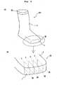
- a sock (tubular knitted fabric) including a toe inserting section for individually inserting a toe inside the sock can be knitted by applying the knitting method described in the first embodiment.
- Fig. 4A is a schematic view of the sock
- Fig. 4B is an enlarged view of a toe portion of the sock.
- the partitioning sections 3 are knitted to a predetermined length, the end on a top portion 10 side of each of the partitioning sections 3 is subjected to the bind-off process and the main body section 2 is knitted to a tubular shape, so that the top portion 10 having a rib structure can be knitted and the sock 101 can be completed.
- the base surface 1 is formed at the most distal end of the toe portion 30, the partitioning sections 3 are formed in the tube formed by the main body section 2 and the base surface 1, and the toe inserting section for inserting the toe is formed between the proximate partitioning sections 3, 3.
- the partitioning sections 3 are set up from the base surface 1, and thus the toes inserted to each toe inserting section do not touch each other when the sock 101 is worn, thus realizing the sock 101 that is comfortable to wear.
- the present invention is not limited to the embodiments described above, and can be appropriately modified and implemented within a scope not deviating from the gist of the invention.
- the base surface 1 and the main body section 2 may have a rib structure.
Landscapes
- Engineering & Computer Science (AREA)
- Textile Engineering (AREA)
- Knitting Of Fabric (AREA)
- Knitting Machines (AREA)
Applications Claiming Priority (1)
| Application Number | Priority Date | Filing Date | Title |
|---|---|---|---|
| JP2011100912A JP5695962B2 (ja) | 2011-04-28 | 2011-04-28 | 筒状編地の編成方法、および筒状編地 |
Publications (2)
| Publication Number | Publication Date |
|---|---|
| EP2518198A1 EP2518198A1 (en) | 2012-10-31 |
| EP2518198B1 true EP2518198B1 (en) | 2015-06-03 |
Family
ID=46044163
Family Applications (1)
| Application Number | Title | Priority Date | Filing Date |
|---|---|---|---|
| EP12002909.5A Active EP2518198B1 (en) | 2011-04-28 | 2012-04-25 | Knitting method of tubular knitted fabric, and tubular knitted fabric |
Country Status (4)
| Country | Link |
|---|---|
| EP (1) | EP2518198B1 (enExample) |
| JP (1) | JP5695962B2 (enExample) |
| KR (1) | KR101377442B1 (enExample) |
| CN (1) | CN102758302B (enExample) |
Families Citing this family (3)
| Publication number | Priority date | Publication date | Assignee | Title |
|---|---|---|---|---|
| TWI596249B (zh) * | 2013-04-04 | 2017-08-21 | 島精機製作所股份有限公司 | 鞋襪類之編織方法 |
| JP6292914B2 (ja) * | 2014-02-12 | 2018-03-14 | 株式会社島精機製作所 | 筒状編地の編成方法 |
| DE102015206301B4 (de) * | 2015-04-09 | 2016-10-27 | Adidas Ag | Gestrickter Beutel |
Family Cites Families (9)
| Publication number | Priority date | Publication date | Assignee | Title |
|---|---|---|---|---|
| DE4008057A1 (de) * | 1990-03-14 | 1991-09-19 | Stoll & Co H | Gestrickgebilde |
| JP2001355155A (ja) | 2000-06-12 | 2001-12-26 | Susumu Yumura | 足先編地およびこの足先編地を用いたストッキング |
| CN2605279Y (zh) * | 2002-12-08 | 2004-03-03 | 青岛增井贸易有限公司 | 分趾编织袜 |
| JP4336307B2 (ja) * | 2004-12-28 | 2009-09-30 | 株式会社島精機製作所 | 二重の筒状編地の編成方法 |
| JP4769059B2 (ja) * | 2005-10-21 | 2011-09-07 | 株式会社島精機製作所 | 仕切りを有する筒状編地およびその編成方法 |
| JP2010511108A (ja) | 2006-12-01 | 2010-04-08 | ナイキ インターナショナル リミテッド | 靴下及びその製造方法 |
| WO2008143172A1 (ja) * | 2007-05-18 | 2008-11-27 | Shima Seiki Manufacturing, Ltd. | 3次元編物の編成方法とこれを用いた3次元編物 |
| CN102471960B (zh) | 2009-08-12 | 2013-11-27 | 株式会社岛精机制作所 | 针织物的编织方法及针织物 |
| JP5875240B2 (ja) * | 2011-03-25 | 2016-03-02 | 株式会社島精機製作所 | 仕切りを有する筒状編地およびその編成方法 |
-
2011
- 2011-04-28 JP JP2011100912A patent/JP5695962B2/ja active Active
-
2012
- 2012-03-14 KR KR1020120025867A patent/KR101377442B1/ko active Active
- 2012-04-18 CN CN201210115237.5A patent/CN102758302B/zh active Active
- 2012-04-25 EP EP12002909.5A patent/EP2518198B1/en active Active
Also Published As
| Publication number | Publication date |
|---|---|
| KR20120122880A (ko) | 2012-11-07 |
| EP2518198A1 (en) | 2012-10-31 |
| JP2012233269A (ja) | 2012-11-29 |
| CN102758302B (zh) | 2014-12-31 |
| JP5695962B2 (ja) | 2015-04-08 |
| KR101377442B1 (ko) | 2014-03-25 |
| CN102758302A (zh) | 2012-10-31 |
Similar Documents
| Publication | Publication Date | Title |
|---|---|---|
| US20040093907A1 (en) | Knitted fabric having open part and knitting method therefor | |
| EP2982787B1 (en) | Method for knitting footwear | |
| JP6541621B2 (ja) | 筒状編地の編成方法、および筒状編地 | |
| EP2511404B1 (en) | Tubular knit fabric and knitting method thereof | |
| KR102168787B1 (ko) | 편성포의 편성방법 | |
| EP2530196B1 (en) | Knitting method of knitted fabric with hole and knitted fabric | |
| EP2468934B1 (en) | Knitting method of knitted fabric having multilayered structure | |
| EP2453046B1 (en) | Knitwear with sleeves and body, and knitting method for same | |
| JP6211482B2 (ja) | フットウェアの編成方法 | |
| US6935140B2 (en) | Method of knitting tubular knitted fabric | |
| EP2385160B1 (en) | Knitting method of tubular knitted fabric | |
| EP2518198B1 (en) | Knitting method of tubular knitted fabric, and tubular knitted fabric | |
| EP1672105A1 (en) | Method of knitting knitwear garment with raglan sleeves and knitwear garment with raglan sleeves | |
| CN102965802A (zh) | 折回编织方法及针织物 | |
| EP1829995B1 (en) | Knitwear knitted by weft knitting machine and method of knitting the same | |
| JPH08158208A (ja) | 切りポケットを有する編地およびその編成方法 | |
| KR101844254B1 (ko) | 손가락부가 달린 편성포 및 그 편성방법 | |
| KR20220078487A (ko) | 편성방법 | |
| US10184196B2 (en) | Method for knitting knitted fabric | |
| KR20040075907A (ko) | 칼라 형성방법 | |
| JP4769059B2 (ja) | 仕切りを有する筒状編地およびその編成方法 | |
| EP1835058B1 (en) | Method of knitting tubular fabric | |
| JP2009144292A (ja) | 指袋付き編地およびその編成方法 | |
| JPH10204710A (ja) | ニット用衿編地 | |
| JP2017210697A (ja) | 筒状編地の編成方法 |
Legal Events
| Date | Code | Title | Description |
|---|---|---|---|
| PUAI | Public reference made under article 153(3) epc to a published international application that has entered the european phase |
Free format text: ORIGINAL CODE: 0009012 |
|
| AK | Designated contracting states |
Kind code of ref document: A1 Designated state(s): AL AT BE BG CH CY CZ DE DK EE ES FI FR GB GR HR HU IE IS IT LI LT LU LV MC MK MT NL NO PL PT RO RS SE SI SK SM TR |
|
| AX | Request for extension of the european patent |
Extension state: BA ME |
|
| 17P | Request for examination filed |
Effective date: 20130103 |
|
| GRAP | Despatch of communication of intention to grant a patent |
Free format text: ORIGINAL CODE: EPIDOSNIGR1 |
|
| RIC1 | Information provided on ipc code assigned before grant |
Ipc: D04B 1/26 20060101ALN20141215BHEP Ipc: D04B 1/10 20060101ALN20141215BHEP Ipc: D04B 1/22 20060101AFI20141215BHEP |
|
| INTG | Intention to grant announced |
Effective date: 20150112 |
|
| GRAS | Grant fee paid |
Free format text: ORIGINAL CODE: EPIDOSNIGR3 |
|
| GRAA | (expected) grant |
Free format text: ORIGINAL CODE: 0009210 |
|
| AK | Designated contracting states |
Kind code of ref document: B1 Designated state(s): AL AT BE BG CH CY CZ DE DK EE ES FI FR GB GR HR HU IE IS IT LI LT LU LV MC MK MT NL NO PL PT RO RS SE SI SK SM TR |
|
| REG | Reference to a national code |
Ref country code: GB Ref legal event code: FG4D |
|
| REG | Reference to a national code |
Ref country code: CH Ref legal event code: EP |
|
| REG | Reference to a national code |
Ref country code: AT Ref legal event code: REF Ref document number: 729998 Country of ref document: AT Kind code of ref document: T Effective date: 20150715 Ref country code: IE Ref legal event code: FG4D |
|
| REG | Reference to a national code |
Ref country code: DE Ref legal event code: R096 Ref document number: 602012007654 Country of ref document: DE |
|
| REG | Reference to a national code |
Ref country code: AT Ref legal event code: MK05 Ref document number: 729998 Country of ref document: AT Kind code of ref document: T Effective date: 20150603 |
|
| PG25 | Lapsed in a contracting state [announced via postgrant information from national office to epo] |
Ref country code: LT Free format text: LAPSE BECAUSE OF FAILURE TO SUBMIT A TRANSLATION OF THE DESCRIPTION OR TO PAY THE FEE WITHIN THE PRESCRIBED TIME-LIMIT Effective date: 20150603 Ref country code: ES Free format text: LAPSE BECAUSE OF FAILURE TO SUBMIT A TRANSLATION OF THE DESCRIPTION OR TO PAY THE FEE WITHIN THE PRESCRIBED TIME-LIMIT Effective date: 20150603 Ref country code: NO Free format text: LAPSE BECAUSE OF FAILURE TO SUBMIT A TRANSLATION OF THE DESCRIPTION OR TO PAY THE FEE WITHIN THE PRESCRIBED TIME-LIMIT Effective date: 20150903 Ref country code: HR Free format text: LAPSE BECAUSE OF FAILURE TO SUBMIT A TRANSLATION OF THE DESCRIPTION OR TO PAY THE FEE WITHIN THE PRESCRIBED TIME-LIMIT Effective date: 20150603 Ref country code: FI Free format text: LAPSE BECAUSE OF FAILURE TO SUBMIT A TRANSLATION OF THE DESCRIPTION OR TO PAY THE FEE WITHIN THE PRESCRIBED TIME-LIMIT Effective date: 20150603 |
|
| REG | Reference to a national code |
Ref country code: NL Ref legal event code: MP Effective date: 20150603 |
|
| REG | Reference to a national code |
Ref country code: LT Ref legal event code: MG4D |
|
| PG25 | Lapsed in a contracting state [announced via postgrant information from national office to epo] |
Ref country code: AT Free format text: LAPSE BECAUSE OF FAILURE TO SUBMIT A TRANSLATION OF THE DESCRIPTION OR TO PAY THE FEE WITHIN THE PRESCRIBED TIME-LIMIT Effective date: 20150603 Ref country code: RS Free format text: LAPSE BECAUSE OF FAILURE TO SUBMIT A TRANSLATION OF THE DESCRIPTION OR TO PAY THE FEE WITHIN THE PRESCRIBED TIME-LIMIT Effective date: 20150603 Ref country code: GR Free format text: LAPSE BECAUSE OF FAILURE TO SUBMIT A TRANSLATION OF THE DESCRIPTION OR TO PAY THE FEE WITHIN THE PRESCRIBED TIME-LIMIT Effective date: 20150904 Ref country code: BG Free format text: LAPSE BECAUSE OF FAILURE TO SUBMIT A TRANSLATION OF THE DESCRIPTION OR TO PAY THE FEE WITHIN THE PRESCRIBED TIME-LIMIT Effective date: 20150903 Ref country code: LV Free format text: LAPSE BECAUSE OF FAILURE TO SUBMIT A TRANSLATION OF THE DESCRIPTION OR TO PAY THE FEE WITHIN THE PRESCRIBED TIME-LIMIT Effective date: 20150603 |
|
| PG25 | Lapsed in a contracting state [announced via postgrant information from national office to epo] |
Ref country code: EE Free format text: LAPSE BECAUSE OF FAILURE TO SUBMIT A TRANSLATION OF THE DESCRIPTION OR TO PAY THE FEE WITHIN THE PRESCRIBED TIME-LIMIT Effective date: 20150603 |
|
| PG25 | Lapsed in a contracting state [announced via postgrant information from national office to epo] |
Ref country code: PL Free format text: LAPSE BECAUSE OF FAILURE TO SUBMIT A TRANSLATION OF THE DESCRIPTION OR TO PAY THE FEE WITHIN THE PRESCRIBED TIME-LIMIT Effective date: 20150603 Ref country code: SK Free format text: LAPSE BECAUSE OF FAILURE TO SUBMIT A TRANSLATION OF THE DESCRIPTION OR TO PAY THE FEE WITHIN THE PRESCRIBED TIME-LIMIT Effective date: 20150603 Ref country code: CZ Free format text: LAPSE BECAUSE OF FAILURE TO SUBMIT A TRANSLATION OF THE DESCRIPTION OR TO PAY THE FEE WITHIN THE PRESCRIBED TIME-LIMIT Effective date: 20150603 Ref country code: IS Free format text: LAPSE BECAUSE OF FAILURE TO SUBMIT A TRANSLATION OF THE DESCRIPTION OR TO PAY THE FEE WITHIN THE PRESCRIBED TIME-LIMIT Effective date: 20151003 Ref country code: RO Free format text: LAPSE BECAUSE OF NON-PAYMENT OF DUE FEES Effective date: 20150603 Ref country code: PT Free format text: LAPSE BECAUSE OF FAILURE TO SUBMIT A TRANSLATION OF THE DESCRIPTION OR TO PAY THE FEE WITHIN THE PRESCRIBED TIME-LIMIT Effective date: 20151006 |
|
| REG | Reference to a national code |
Ref country code: DE Ref legal event code: R097 Ref document number: 602012007654 Country of ref document: DE |
|
| PLBE | No opposition filed within time limit |
Free format text: ORIGINAL CODE: 0009261 |
|
| STAA | Information on the status of an ep patent application or granted ep patent |
Free format text: STATUS: NO OPPOSITION FILED WITHIN TIME LIMIT |
|
| PG25 | Lapsed in a contracting state [announced via postgrant information from national office to epo] |
Ref country code: DK Free format text: LAPSE BECAUSE OF FAILURE TO SUBMIT A TRANSLATION OF THE DESCRIPTION OR TO PAY THE FEE WITHIN THE PRESCRIBED TIME-LIMIT Effective date: 20150603 |
|
| 26N | No opposition filed |
Effective date: 20160304 |
|
| PG25 | Lapsed in a contracting state [announced via postgrant information from national office to epo] |
Ref country code: SI Free format text: LAPSE BECAUSE OF FAILURE TO SUBMIT A TRANSLATION OF THE DESCRIPTION OR TO PAY THE FEE WITHIN THE PRESCRIBED TIME-LIMIT Effective date: 20150603 |
|
| PG25 | Lapsed in a contracting state [announced via postgrant information from national office to epo] |
Ref country code: BE Free format text: LAPSE BECAUSE OF NON-PAYMENT OF DUE FEES Effective date: 20160430 |
|
| REG | Reference to a national code |
Ref country code: CH Ref legal event code: PL |
|
| GBPC | Gb: european patent ceased through non-payment of renewal fee |
Effective date: 20160425 |
|
| PG25 | Lapsed in a contracting state [announced via postgrant information from national office to epo] |
Ref country code: LU Free format text: LAPSE BECAUSE OF FAILURE TO SUBMIT A TRANSLATION OF THE DESCRIPTION OR TO PAY THE FEE WITHIN THE PRESCRIBED TIME-LIMIT Effective date: 20160425 Ref country code: BE Free format text: LAPSE BECAUSE OF FAILURE TO SUBMIT A TRANSLATION OF THE DESCRIPTION OR TO PAY THE FEE WITHIN THE PRESCRIBED TIME-LIMIT Effective date: 20150603 |
|
| REG | Reference to a national code |
Ref country code: IE Ref legal event code: MM4A |
|
| REG | Reference to a national code |
Ref country code: FR Ref legal event code: ST Effective date: 20161230 |
|
| PG25 | Lapsed in a contracting state [announced via postgrant information from national office to epo] |
Ref country code: CH Free format text: LAPSE BECAUSE OF NON-PAYMENT OF DUE FEES Effective date: 20160430 Ref country code: FR Free format text: LAPSE BECAUSE OF NON-PAYMENT OF DUE FEES Effective date: 20160502 Ref country code: GB Free format text: LAPSE BECAUSE OF NON-PAYMENT OF DUE FEES Effective date: 20160425 Ref country code: LI Free format text: LAPSE BECAUSE OF NON-PAYMENT OF DUE FEES Effective date: 20160430 |
|
| PG25 | Lapsed in a contracting state [announced via postgrant information from national office to epo] |
Ref country code: IE Free format text: LAPSE BECAUSE OF NON-PAYMENT OF DUE FEES Effective date: 20160425 |
|
| PG25 | Lapsed in a contracting state [announced via postgrant information from national office to epo] |
Ref country code: SE Free format text: LAPSE BECAUSE OF FAILURE TO SUBMIT A TRANSLATION OF THE DESCRIPTION OR TO PAY THE FEE WITHIN THE PRESCRIBED TIME-LIMIT Effective date: 20150603 Ref country code: NL Free format text: LAPSE BECAUSE OF FAILURE TO SUBMIT A TRANSLATION OF THE DESCRIPTION OR TO PAY THE FEE WITHIN THE PRESCRIBED TIME-LIMIT Effective date: 20150603 |
|
| PG25 | Lapsed in a contracting state [announced via postgrant information from national office to epo] |
Ref country code: SM Free format text: LAPSE BECAUSE OF FAILURE TO SUBMIT A TRANSLATION OF THE DESCRIPTION OR TO PAY THE FEE WITHIN THE PRESCRIBED TIME-LIMIT Effective date: 20150603 Ref country code: HU Free format text: LAPSE BECAUSE OF FAILURE TO SUBMIT A TRANSLATION OF THE DESCRIPTION OR TO PAY THE FEE WITHIN THE PRESCRIBED TIME-LIMIT; INVALID AB INITIO Effective date: 20120425 Ref country code: CY Free format text: LAPSE BECAUSE OF FAILURE TO SUBMIT A TRANSLATION OF THE DESCRIPTION OR TO PAY THE FEE WITHIN THE PRESCRIBED TIME-LIMIT Effective date: 20150603 |
|
| PG25 | Lapsed in a contracting state [announced via postgrant information from national office to epo] |
Ref country code: MC Free format text: LAPSE BECAUSE OF FAILURE TO SUBMIT A TRANSLATION OF THE DESCRIPTION OR TO PAY THE FEE WITHIN THE PRESCRIBED TIME-LIMIT Effective date: 20150603 Ref country code: MT Free format text: LAPSE BECAUSE OF NON-PAYMENT OF DUE FEES Effective date: 20160430 Ref country code: MK Free format text: LAPSE BECAUSE OF FAILURE TO SUBMIT A TRANSLATION OF THE DESCRIPTION OR TO PAY THE FEE WITHIN THE PRESCRIBED TIME-LIMIT Effective date: 20150603 Ref country code: TR Free format text: LAPSE BECAUSE OF FAILURE TO SUBMIT A TRANSLATION OF THE DESCRIPTION OR TO PAY THE FEE WITHIN THE PRESCRIBED TIME-LIMIT Effective date: 20150603 |
|
| PG25 | Lapsed in a contracting state [announced via postgrant information from national office to epo] |
Ref country code: AL Free format text: LAPSE BECAUSE OF FAILURE TO SUBMIT A TRANSLATION OF THE DESCRIPTION OR TO PAY THE FEE WITHIN THE PRESCRIBED TIME-LIMIT Effective date: 20150603 |
|
| PGFP | Annual fee paid to national office [announced via postgrant information from national office to epo] |
Ref country code: IT Payment date: 20250320 Year of fee payment: 14 |
|
| PGFP | Annual fee paid to national office [announced via postgrant information from national office to epo] |
Ref country code: DE Payment date: 20250305 Year of fee payment: 14 |