EP2518005A1 - Industrial truck - Google Patents
Industrial truck Download PDFInfo
- Publication number
- EP2518005A1 EP2518005A1 EP12158762A EP12158762A EP2518005A1 EP 2518005 A1 EP2518005 A1 EP 2518005A1 EP 12158762 A EP12158762 A EP 12158762A EP 12158762 A EP12158762 A EP 12158762A EP 2518005 A1 EP2518005 A1 EP 2518005A1
- Authority
- EP
- European Patent Office
- Prior art keywords
- load
- truck
- arms
- drive part
- load arms
- Prior art date
- Legal status (The legal status is an assumption and is not a legal conclusion. Google has not performed a legal analysis and makes no representation as to the accuracy of the status listed.)
- Granted
Links
Images


Classifications
-
- B—PERFORMING OPERATIONS; TRANSPORTING
- B66—HOISTING; LIFTING; HAULING
- B66F—HOISTING, LIFTING, HAULING OR PUSHING, NOT OTHERWISE PROVIDED FOR, e.g. DEVICES WHICH APPLY A LIFTING OR PUSHING FORCE DIRECTLY TO THE SURFACE OF A LOAD
- B66F9/00—Devices for lifting or lowering bulky or heavy goods for loading or unloading purposes
- B66F9/06—Devices for lifting or lowering bulky or heavy goods for loading or unloading purposes movable, with their loads, on wheels or the like, e.g. fork-lift trucks
- B66F9/075—Constructional features or details
- B66F9/07559—Stabilizing means
-
- B—PERFORMING OPERATIONS; TRANSPORTING
- B66—HOISTING; LIFTING; HAULING
- B66F—HOISTING, LIFTING, HAULING OR PUSHING, NOT OTHERWISE PROVIDED FOR, e.g. DEVICES WHICH APPLY A LIFTING OR PUSHING FORCE DIRECTLY TO THE SURFACE OF A LOAD
- B66F9/00—Devices for lifting or lowering bulky or heavy goods for loading or unloading purposes
- B66F9/06—Devices for lifting or lowering bulky or heavy goods for loading or unloading purposes movable, with their loads, on wheels or the like, e.g. fork-lift trucks
- B66F9/075—Constructional features or details
- B66F9/07545—Overhead guards
-
- B—PERFORMING OPERATIONS; TRANSPORTING
- B66—HOISTING; LIFTING; HAULING
- B66F—HOISTING, LIFTING, HAULING OR PUSHING, NOT OTHERWISE PROVIDED FOR, e.g. DEVICES WHICH APPLY A LIFTING OR PUSHING FORCE DIRECTLY TO THE SURFACE OF A LOAD
- B66F9/00—Devices for lifting or lowering bulky or heavy goods for loading or unloading purposes
- B66F9/06—Devices for lifting or lowering bulky or heavy goods for loading or unloading purposes movable, with their loads, on wheels or the like, e.g. fork-lift trucks
- B66F9/075—Constructional features or details
- B66F9/0759—Details of operating station, e.g. seats, levers, operator platforms, cabin suspension
-
- B—PERFORMING OPERATIONS; TRANSPORTING
- B66—HOISTING; LIFTING; HAULING
- B66F—HOISTING, LIFTING, HAULING OR PUSHING, NOT OTHERWISE PROVIDED FOR, e.g. DEVICES WHICH APPLY A LIFTING OR PUSHING FORCE DIRECTLY TO THE SURFACE OF A LOAD
- B66F9/00—Devices for lifting or lowering bulky or heavy goods for loading or unloading purposes
- B66F9/06—Devices for lifting or lowering bulky or heavy goods for loading or unloading purposes movable, with their loads, on wheels or the like, e.g. fork-lift trucks
- B66F9/075—Constructional features or details
- B66F9/12—Platforms; Forks; Other load supporting or gripping members
- B66F9/16—Platforms; Forks; Other load supporting or gripping members inclinable relative to mast
- B66F9/165—Foldable forks, i.e. where only the horizontal section moves
Definitions
- the invention relates to an industrial truck with a drive part and a load part, which has a relative to the drive part liftable and lowerable load-receiving means, wherein the drive member is provided with a chassis having at least one wheel on a load-facing area and at least one wheel on a load remote area.
- a tricycle landing gear in this case usually consists of two arranged on the load-facing portion of the drive member close-coupled wheels and a third remote from the load area of the drive part remote load wheel.
- the two arranged at the load-near area wheels are designed as non-steerable wheels in such a tricycle landing gear, wherein the third, arranged on the remote area remote wheel is designed as a steerable drive wheel.
- a four-wheel drive consists of two wheels arranged close to the load and two wheels arranged at the distance from the load.
- the two wheels arranged at the area close to the load are designed as drive wheels, wherein the two wheels remote from the load are designed as non-driven steerable wheels.
- the load-distant region of the drive part forms a counterweight, which essentially determines the carrying capacity of the industrial truck and the weight of the load which can be received by the load-receiving means.
- counterbalance forklifts are designed with a counterweight designed as a cast body Warehouse forklifts, which are used for storing and retrieving goods or for picking goods in a warehouse and / or in a rack system, only partially suitable, since counterbalanced forklifts compared to warehouse trucks require increased operating widths and thus in a rack system of available storage space not efficient can be exploited.
- the required counterweight in counterbalanced forklifts also forms part of the vehicle mass, which must be accelerated and moved while driving the truck and thus contributes to the energy consumption of the truck. If the truck is used to handle small, light loads that are below the truck's maximum capacity, the presence of a counterweight designed for maximum carrying capacity will result in increased energy consumption.
- a traction battery for supplying the load of an electric drive system which must be charged at certain intervals or replaced with a charged traction battery, a low energy consumption is desired to a possible long operating time with a charge of the traction battery to achieve.
- the DE 10 2007 049 392 A1 discloses a generic truck, in which a load-receiving means outside the wheel base of the drive part is arranged and in which the traction battery acts as a counterweight, so that the truck has compact dimensions in the vehicle longitudinal direction and can be used as a warehouse truck in a warehouse or a rack system. Due to the limited weight of the traction battery, however, such a truck has only a low load capacity and is not suitable for the handling of heavy loads.
- the present invention has for its object to provide a truck of the type mentioned available, which has a high load capacity with compact dimensions and low vehicle mass.
- the truck is provided with load arms, which are arranged to be adjustable on the drive part between a non-operating position and an operating position, wherein the load arms are in the operating position below the lifting device and the load arms to the lastteil paragraphen ends with at least one Load roller device are provided as additional landing gear.
- the truck with in the inoperative position load arms on a first load capacity, which is less than the maximum load capacity and allows the handling of small, light and medium loads. If the truck is to be used to handle large, heavy loads, by adjusting the load arms in the operating position, the load capacity can be increased to the maximum load capacity.
- additional load arms thus make it possible in a simple manner that the truck has a chassis in the operating position of the load arms, which is formed by the load roller devices on the loadteil paragraphen ends of the load arms and the at least one load remote wheel on the drive part, so that in in the operating position an extended wheelbase is achieved and the load arranged on the load-carrying means is carried within the wheel base of the truck.
- the truck according to the invention thus makes it possible that at low vehicle mass by the load arms located in the operating position, the corresponding loadteil workede load supports, the handling of heavy loads at high load capacity is possible, which by a low vehicle mass high energy efficiency with low energy consumption of the invention Truck can be achieved.
- the truck has compact dimensions in the vehicle longitudinal direction, whereby the use of the truck as a warehouse trucks in shelf deposits and in narrow storage lanes and driveways is facilitated.
- the load arms are in the inoperative position within the contour of the drive member. In the Inoperative position of the load arms thus has the truck compact dimensions and high maneuverability.
- the truck is supported in the inoperative position of the load arms with the wheels of the drive part on a roadway.
- the truck according to the invention with the wheels of the drive part forms a tricycle or a four-wheel drive.
- the truck according to the invention thus operates on the type of a counterbalance forklift, in which the load is arranged outside the wheel base and is taken up cantilevered.
- the truck In the operating position of the load arms, the truck is supported according to a preferred embodiment of the invention with the load roller device on the load arms and the at least one wheel on the load distant area of the drive part on the road.
- the load roller device on the load arms In the operating position of the load arms can thus be formed in a simple way with the load roller devices on the load arms and the at least one wheel on the load remote area of the drive part, a tricycle or a four-wheel drive with extended wheelbase.
- the at least one load near the wheel on the drive part of the road is lifted.
- the truck according to the invention operates in the manner of a Radarmstaplers, wherein the load is disposed within the wheel base and is recorded.
- the load arms can be arranged hinged or pivotable about a horizontal or a vertical pivot axis on the drive part between the inoperative position and the operating position. According to a preferred embodiment of the invention, the load arms are arranged displaceably in the vehicle longitudinal direction on the drive part. A displaceable arrangement of the load arms on the Drive part can be achieved by a corresponding linear guide in a simple manner and with low construction costs.
- the load roller devices can be actively adjusted in height on the load arms and / or the wheels of the drive part close to the load in order to lower them onto the roadway or lift them off the roadway.
- the load roller devices may be fixedly mounted in the load arms, so that no additional lifting movement is achieved on the load arms.
- the load arms of the truck according to the invention thus have in the operating position the function of additional load supports with rotatable load roller devices to carry the load within an extended wheelbase.
- the load arms are provided with an Initialhub friendship.
- an initial lifting device With an initial lifting device, a lifting and lowering movement of the load arms can continue to be achieved, so that the load arms in the operating position form a second load receiving means and with the load arms another charge carrier, such as a pallet, can be handled.
- the truck according to the invention thus enables a double-decker operation in which a first charge carrier can be handled with the load arms and a second charge carrier can be handled with the lifted load-receiving means of the load part.
- the load roller device comprises at least one load roller rotatably mounted in a load roller
- the load roller carrier is pivotally mounted on the load and pivotable by means of a drive device.
- a parallel to the road lift and lowering movement of the load arms are achieved in a simple manner.
- the load-carrying means of the truck according to the invention is formed by a fork comprising two forks, the forks are provided with folding load sections.
- the vehicle length can thus be reduced to the dimensions of the drive part in conjunction with the load arms located in the inoperative position, so that an extremely compact truck is achieved and the use of the truck as storage truck stackable shelters and narrow storage lanes and driveways is relieved.
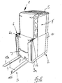
- an inventive truck 1 which comprises a drive part 2 and a load part 3, which is formed by a trained as a load lifting device 4.
- the truck 1 can optionally be operated by an operator or operated in an unmanned automated operation.
- the drive part 2 is provided with a raised and lowered driver safety roof 5.
- the driver's roof 5 in a lowered and retracted position for unmanned automated operation.
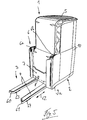
- the truck 1 By lifting and extending the driver's roof 5 upwards, the truck 1 in the in the FIG. 2 shown operating position in which within the raised driver's roof 5 a driver's workplace F is designed for an operator in the drive part 2 and the truck 1 can be operated by an operator.
- a mast 6 for raising and lowering the load-receiving means 4 is arranged.
- the mast 6 consists of two spaced apart in the vehicle transverse direction telescopic mast columns 6a, 6b.
- the load-receiving means 4 designed as a load fork consists of two fork tines 11a, 11b which are arranged on a fork carriage 7 which can be raised and lowered in the telescopic mast 6.
- the forks 11a, 11b have about a horizontal pivot axis 8 hingedly arranged load sections, which can be folded in particular by 90 ° upwards.
- FIG. 1 and 2 are the load sections of the forks 11a, 11b in a downwardly unfolded, substantially horizontal position in which with the forks 11a, 11b, a carrier can be raised.
- FIG. 7 are the folding forks 11a, 11b shown in a folded about the pivot axis 8 upwards position in which the forks 11a, 11b are folded up to the mast 6 and are preferably folded flush with the mast 6.
- the folding movement of the forks 11a, 11b can be achieved by a drive device, not shown.
- the truck 1 is designed as a battery-electrically operated truck, wherein on the second, the mast 6 opposite end portion of the drive part 2 in the FIG. 3 Traction battery 10 shown in more detail, for example, a lithium-ion battery is arranged.
- the load-facing area of the drive part 2 - as in the FIG. 3 is shown in more detail - provided with close-to-wheels 9a.
- at least one load-distant wheel 9b is arranged on the load-remote area of the drive part 2.
- the off-load wheel 9b is designed as a steerable drive wheel, wherein the wheels close to the load 9a are formed as rollers.
- the traction drive is formed by at least one electric traction motor.
- traction battery 10 In the field of traction battery 10 is also a unit space for a working hydraulic unit, not shown, for supplying a lifting drive, formed by means of which the mast 6 arranged on the load-receiving means 4 and is movable up and down to supply possibly existing hydraulic auxiliary drives or additional consumer serves.
- the arranged in the drive part 2 traction battery 10 further has the function of the load part 3 opposite counterweight of the truck 1.
- the traction battery 10 is preferably arranged in the transverse direction of the truck 1 and extends over the entire vehicle width.
- the driver's workplace F for an operator is arranged between the load part 3 and acting as a counterweight 11 traction battery 10 on the drive part 2 and comprises - as in connection with the FIG. 4 is further apparent - designed as a platform platform platform 15 and a driver's seat 16.
- a Ein- and Exit into the driver's workstation 5 can be formed by a door 17 arranged on a vehicle side.
- the driver's workplace F is at the remote end of the drive part 2 by a vertical, arranged in the vehicle transverse direction boundary wall 18 and the door 17 opposite side of the vehicle by a vertical, extending in the vehicle longitudinal boundary wall 19 limited.
- the two boundary walls 18 and 19 are arranged adjacent to each other and merge into each other in a transition region.
- the two boundary walls 18, 19 thus form a side boundary 20 of the driver's workplace F on two adjacent sides aneinder.
- the driver's seat 16 may be slidably disposed along the side boundary 20 formed by the two boundary walls 18, 19 and in the circumferential direction of the side boundary 20 of the driver's workplace F.
- a linear guide means 25 For longitudinal displacement of the driver's seat 16 along the two boundary walls 18, 19, a linear guide means 25 is provided.
- the linear guide means 25 has an arranged on the side boundary 20 and thus the two boundary walls 18, 19 of the driver's workplace F guide rail or cam track 26 on which the driver's seat 16 is arranged by means of a console 27 to achieve various operating positions for the operator slidably.
- the console 27 is preferably located on one side of the driver's seat sixteenth
- the driver's seat 16 is provided with a side armrest 30 on which one or more operating elements 31 are arranged.
- an example designed as a joystick control element 31 is arranged on the armrest 30, with which the drive and / or the steering of the truck 1 can be controlled.
- the driver's seat 16 is preferably designed as a so-called combination seat 40, which has the function of a seat for a seated operating position and the function of a standing aid for a standing operating position of the operator.
- the truck 1 is inventively provided on the drive part 2 with load arms 60, 61 which are connected to the drive part 2 between a in the FIG. 3 as well as the Figures 5 and 6 shown operating position and one in the FIGS. 1 . 2 . 4 and 7 illustrated inoperative position are arranged adjustable.
- the load arms 60, 61 slidably disposed in the bottom region of the drive part 2 in the vehicle longitudinal direction, as in the Figures 3 . 5 and 6 is illustrated by the arrow 62.
- the longitudinal guidance of the load arms 60, 61 can be effected by a linear guide, not shown.
- the displacement movement of the load arms 60, 61 between the inoperative position and the strigstallung can be achieved by means of a drive device not shown.
- the load arms 60, 61 are provided at the lastteil remedyen ends with at least one load roller roller device 63, 64 for support on the driving ban.
- the load roller devices 63, 64 consist of a single roller or alternatively may have a plurality of load rollers, for example, be designed as a tandem roller comprising two load rollers.
- the load rollers 63, 64 on the load arms 60, 61 in contact with the roadway the close-to-wheels 9a are lifted off the drive part 2 of the road.
- the load arms 60, 61 In the extended position of the load arms 60, 61, the load arms 60, 61 are located in the vertical direction under the load-receiving means 4 of the load part 3 formed by the load fork.
- the load arms 60, 61 In the retracted inoperative position are the load arms 60, 61 within the contour of the drive part 2, preferably completely below the drive part 2, and are not in the direction of the load part 3 via.
- the load rollers 63, 64 In the retracted inoperative position of the load arms 60, 61, the load rollers 63, 64 are lifted from the road, so that the truck 1 is supported in the load part side area with the wheels close to the load 9a of the drive part 2 on the road.
- the truck 1 In the inoperative position of the load arms 60, 61, the truck 1 thus has one of the wheels close to the load 9a and the load-distant wheel 9b of the drive part 2 formed chassis, whose wheelbase is determined by the distance of the wheels 9a, 9b in the vehicle longitudinal direction.
- the close-wheels 9a of the drive part 2 are lifted from the road, so that the truck 1 in the load section 3 with the load rollers 63, 64 of the extended load arms 60, 61st supported on the roadway.
- the truck 1 thus has in the operating position of the load arms 60, 61 a of the load rollers 63, 64 of the load arms 60, 61 and the load distant wheel 9b of the drive part 9b formed chassis whose wheelbase by the distance of the load rollers 63, 64 on the load arms 6, 61 and the wheel 9b is determined in the vehicle longitudinal direction.
- the load arms 60, 61 thus have the function of load supports with which the wheelbase of the truck 1 can be extended.
- load arms 60, 61 When in the inoperative position load arms 60, 61, the truck operates in the manner of a counterbalance forklift, in which the load on the load-bearing means 4 is supported outside the wheel base cantilevered.
- load arms 60, 61 in the operative position the load is carried on the load handler 4 within the extended wheel base so that the truck 1 operates in the manner of a wheeled truck.
- the load arms 60, 61 with a by the arrow 65 in the FIG. 6 clarified clarified Initialhub founded that allows a lifting and lowering movement of the load arms 60, 61.
- the load arms 60, 61 thus form an additional load-receiving means in the operating position with which a load carrier, for example a pallet, can be lowered and lifted.
- the load arms 60, 61 thus form a second load receiving means, so that - as shown in Figure 9 - with the load arms 60, 61, a first carrier and with the raised, formed by the load lifting device 4, a second carrier can be handled and the Truck 1 allows a double-deck operation.
- the truck 1 When located in the inoperative load arms 60, 61, the truck 1 due to the acting of the counterweight traction battery 10 a reduced capacity compared to the maximum carrying capacity. With the truck 1 small, light and medium heavy loads can thus be handled by the load-receiving means 4 at low vehicle mass.
- the carrying capacity of the truck 1 by adjusting the load arms 60, 61 are increased to the operating position, so that of the truck 1 with low vehicle mass and without additional counterweight large, heavy loads in the maximum carrying capacity can be handled with low energy consumption.
- the truck 1 according to the invention can thus be adapted in a simple manner in operation to the handling of different heavy loads, in particular by extending the load arms 60, 61 in applications and workflows in which increased load capacity required, the increased capacity to handle heavy Loads is made possible.
- the truck 1 according to the invention has a reduced vehicle mass compared to classic counterbalanced forklifts with a counterweight designed as a cast component and, due to the extendable load arms 60, 61, a comparable maximum load capacity with reduced dimensions in the vehicle longitudinal direction.
- the use of the truck 1 according to the invention is facilitated as a storage truck stackable shelves and narrow storage lanes and driveways at reduced working aisles.
- the truck according to the invention Due to the reduced vehicle mass, the truck according to the invention has a low energy consumption.
- the dimensions of the truck according to the invention are further reduced by the upwardly folding load sections of the forks 11a, 11b, which compact dimensions are achieved with folded forks 11a, 11b for empty runs or in a tractor operation with attached trailers and narrow storage lanes can be traveled.
Abstract
Description
Die Erfindung betrifft ein Flurförderzeug mit einem Antriebsteil und einem Lastteil, das ein bezüglich des Antriebsteils anhebbares und absenkbares Lastaufnahmemittel aufweist, wobei das Antriebsteil mit einem Fahrwerk versehen ist, das zumindest ein Rad an einem lastzugewandten Bereich und zumindest ein Rad an einem lastfernen Bereich aufweist.The invention relates to an industrial truck with a drive part and a load part, which has a relative to the drive part liftable and lowerable load-receiving means, wherein the drive member is provided with a chassis having at least one wheel on a load-facing area and at least one wheel on a load remote area.
Bei derartigen Flurförderzeugen, die mit einem von Rädern an einem Antriebsteil gebildeten, als Dreiradfahrwerk oder Vierradfahrwerk ausgebildeten Fahrwerk auf einer Fahrbahn abgestützt sind, befindet sich das anhebbare und absenkbare Lastaufnahmemittel außerhalb der Radbasis des Fahrwerks an dem Antriebsteil. Ein Dreiradfahrwerk besteht hierbei in der Regel aus zwei am lastzugewandten Bereich des Antriebsteils angeordneten lastnahen Rädern und einem dritten am lastfernen Bereich des Antriebsteils angeordneten lastfernen Rad. In der Regel sind bei einem derartigen Dreiradfahrwerk die beiden am lastnahen Bereich angeordneten Räder als nicht lenkbare Laufräder ausgebildet, wobei das dritte, am lastfernen Bereich angeordnete Rad als lenkbares Antriebsrad ausgebildet ist. Ein Vierradfahrwerk besteht aus zwei am lastnahen Bereich angeordneten Rädern und zwei am lastfernen Bereich angeordneten Rädern. In der Regel sind die beiden am lastnahen Bereich angeordneten Räder als Antriebsräder ausgebildet, wobei die beiden lastfernen Räder als nicht angetriebene lenkbare Räder ausgebildet sind.In such trucks, which are formed with a formed by wheels on a drive part designed as a tricycle landing gear or four-wheel drive chassis on a road, the liftable and lowerable load-carrying means outside the wheel base of the chassis on the drive part. A tricycle landing gear in this case usually consists of two arranged on the load-facing portion of the drive member close-coupled wheels and a third remote from the load area of the drive part remote load wheel. In a rule, the two arranged at the load-near area wheels are designed as non-steerable wheels in such a tricycle landing gear, wherein the third, arranged on the remote area remote wheel is designed as a steerable drive wheel. A four-wheel drive consists of two wheels arranged close to the load and two wheels arranged at the distance from the load. As a rule, the two wheels arranged at the area close to the load are designed as drive wheels, wherein the two wheels remote from the load are designed as non-driven steerable wheels.
Ein gattungsgemäßes Flurförderzeug ist aus der
Bei derartigen Flurförderzeugen bildet der lastferne Bereich des Antriebsteils ein Gegengewicht, das maßgeblich die Tragfähigkeit des Flurförderzeugs und das Gewicht der mit dem Lastaufnahmemittel aufnehmbaren Last bestimmt.In such industrial trucks, the load-distant region of the drive part forms a counterweight, which essentially determines the carrying capacity of the industrial truck and the weight of the load which can be received by the load-receiving means.
Das Gegengewicht trägt jedoch aufgrund der erforderlichen Größe wesentlich zur Baulänge des Flurförderzeugs bei. Aus diesem Grund sind klassische Gegengewichtsgabelstapler mit einem als Gußkörper ausgebildeten Gegengewicht als Lagertechnikstapler, die zum Ein- und Auslagern von Waren oder zum Kommissionieren von Waren in einem Lager und/oder in einer Regalanlage eingesetzt werden, nur bedingt geeignet, da Gegengewichtsgabelstapler gegenüber Lagertechnikstaplern vergrößerte Arbeitsgangsbreiten erfordern und somit in einer Regalanlage der zur Verfügung stehende Lagerraum nicht effizient ausgenutzt werden kann.However, the counterweight contributes significantly to the overall length of the truck due to the required size. For this reason, classical counterbalance forklifts are designed with a counterweight designed as a cast body Warehouse forklifts, which are used for storing and retrieving goods or for picking goods in a warehouse and / or in a rack system, only partially suitable, since counterbalanced forklifts compared to warehouse trucks require increased operating widths and thus in a rack system of available storage space not efficient can be exploited.
Das erforderliche Gegengewicht bei Gegengewichtsgabelstaplern bildet weiterhin einen Bestandteil der Fahrzeugmasse, die im Fahrbetrieb des Flurförderzeugs beschleunigt und bewegt werden muss und somit zum Energieverbrauch des Flurförderzeugs beiträgt. Sofern das Flurförderzeug zur Handhabung von kleinen, leichten Lasten eingesetzt wird, die unterhalb der maximalen Tragfähigkeit des Flurförderzeugs liegen, führt das Vorhandensein eines auf die maximale Tragfähigkeit ausgelegten Gegengewichts zu einem Mehrverbrauch an Energie. Insbesondere bei batterie-elektrisch betriebenen Flurförderzeugen, bei denen als elektrische Energiequelle eine Traktionsbatterie zur Versorgung der Verbraucher eines elektrischen Antriebssystem eingesetzt wird, die in bestimmten Zeitabständen aufgeladen werden muss oder gegen eine aufgeladene Traktionsbatterie ausgetauscht werden muss, ist ein sparsamer Energieverbrauch gewünscht, um eine möglichst lange Betriebszeit mit einer Ladung der Traktionsbatterie zu erzielen.The required counterweight in counterbalanced forklifts also forms part of the vehicle mass, which must be accelerated and moved while driving the truck and thus contributes to the energy consumption of the truck. If the truck is used to handle small, light loads that are below the truck's maximum capacity, the presence of a counterweight designed for maximum carrying capacity will result in increased energy consumption. In particular, in battery-powered industrial trucks, where as a source of electrical energy a traction battery for supplying the load of an electric drive system is used, which must be charged at certain intervals or replaced with a charged traction battery, a low energy consumption is desired to a possible long operating time with a charge of the traction battery to achieve.
Die
Der vorliegenden Erfindung liegt die Aufgabe zugrunde, ein Flurförderzeug der eingangs genannten Gattung zur Verfügung zu stellen, das bei kompakten Abmessungen und geringer Fahrzeugmasse eine hohe Tragfähigkeit aufweist.The present invention has for its object to provide a truck of the type mentioned available, which has a high load capacity with compact dimensions and low vehicle mass.
Diese Aufgabe wird erfindungsgemäß dadurch gelöst, dass das Flurförderzeug mit Lastarmen versehen ist, die an dem Antriebsteil zwischen einer Außerbetriebsstellung und einer Betriebsstellung verstellbar angeordnet sind, wobei sich die Lastarme in der Betriebsstellung unterhalb des Lastaufnahmemittels befinden und die Lastarme an den lastteilseitigen Enden mit mindestens einer Lastrolleneinrichtung als Zusatzfahrwerk versehen sind.This object is achieved in that the truck is provided with load arms, which are arranged to be adjustable on the drive part between a non-operating position and an operating position, wherein the load arms are in the operating position below the lifting device and the load arms to the lastteilseitigen ends with at least one Load roller device are provided as additional landing gear.
Bevorzugt weist das Flurförderzeug mit in der Außerbetriebsstellung befindlichen Lastarmen eine erste Tragfähigkeit auf, die geringer als die maximale Tragfähigkeit ist und die Handhabung von kleinen, leichten und mittelschweren Lasten ermöglicht. Sofern das Flurförderzeug zur Handhabung von großen, schweren Lasten eingesetzt werden soll, kann durch Verstellen der Lastarme in die Betriebsstellung die Tragfähigkeit auf die maximale Tragfähigkeit angehoben werden. Derartige zusätzliche Lastarme ermöglichen es somit auf einfache Weise, dass das Flurförderzeug in der Betriebsstellung der Lastarme ein Fahrwerk aufweist, das von den Lastrolleneinrichtungen an den lastteilseitigen Enden der Lastarmen und dem mindestens einen lastfernen Rad an dem Antriebsteil gebildet ist, so dass bei in der Betriebsstellung befindlichen Lastarme ein verlängerter Radstand erzielt wird und die auf dem Lastaufnahmemittel angeordnete Last innerhalb der Radbasis des Flurförderzeugs getragen wird. Durch Verstellen der Lastarme in die Betriebsstellung kann bei dem erfindungsgemäßen Flurförderzeug auch ohne Gebrauch eines schweren Gegengewichts eine erhöhte maximale Tragfähigkeit erzielt werden und somit eine Handhabung von schweren Lasten erzielt werden. Das erfindungsgemäße Flurförderzeug ermöglicht es somit, dass bei geringer Fahrzeugmasse durch die in der Betriebsstellung befindlichen Lastarme, die entsprechende lastteilseitige Laststützen bilden, die Handhabung von schweren Lasten bei hoher Tragfähigkeit ermöglicht wird, wodurch durch eine geringe Fahrzeugmasse eine hohe Energieeffizient mit einem geringen Energieverbrauch des erfindungsgemäßen Flurförderzeugs erzielt werden kann. Zudem weist das Flurförderzeug in Fahrzeuglängsrichtung kompakte Abmessungen auf, wodurch der Einsatz des Flurförderzeugs als Lagertechnikstapler in Regaleinlagen und in engen Lagergassen sowie Einfahrten erleichtert wird.Preferably, the truck with in the inoperative position load arms on a first load capacity, which is less than the maximum load capacity and allows the handling of small, light and medium loads. If the truck is to be used to handle large, heavy loads, by adjusting the load arms in the operating position, the load capacity can be increased to the maximum load capacity. Such additional load arms thus make it possible in a simple manner that the truck has a chassis in the operating position of the load arms, which is formed by the load roller devices on the loadteilseitigen ends of the load arms and the at least one load remote wheel on the drive part, so that in in the operating position an extended wheelbase is achieved and the load arranged on the load-carrying means is carried within the wheel base of the truck. By adjusting the load arms in the operating position in the truck according to the invention, even without the use of a heavy counterweight increased maximum carrying capacity can be achieved and thus handling of heavy loads can be achieved. The truck according to the invention thus makes it possible that at low vehicle mass by the load arms located in the operating position, the corresponding loadteilseitige load supports, the handling of heavy loads at high load capacity is possible, which by a low vehicle mass high energy efficiency with low energy consumption of the invention Truck can be achieved. In addition, the truck has compact dimensions in the vehicle longitudinal direction, whereby the use of the truck as a warehouse trucks in shelf deposits and in narrow storage lanes and driveways is facilitated.
Gemäß einer bevorzugten Ausführungsform der Erfindung befinden sich die Lastarme in der Außerbetriebsstellung innerhalb der Kontur des Antriebsteils. In der Außerbetriebsstellung der Lastarme weist somit das Flurförderzeug kompakte Abmessungen und eine hohe Wendigkeit auf.According to a preferred embodiment of the invention, the load arms are in the inoperative position within the contour of the drive member. In the Inoperative position of the load arms thus has the truck compact dimensions and high maneuverability.
Gemäß einer bevorzugten Weiterbildung der Erfindung stützt sich das Flurförderzeug in der Außerbetriebsstellung der Lastarme mit den Rädern des Antriebsteils auf einer Fahrbahn ab. In der Außerbetriebsstellung der Lastarme bildet somit das erfindungsgemäße Flurförderzeug mit den Rädern des Antriebsteils ein Dreiradfahrwerk bzw. ein Vierradfahrwerk. In der Außerbetriebsstellung der Lastarme, wobei die Lastrolleneinrichtungen an den Lastarmen von der Fahrbahn abgehoben sind, arbeitet das erfindungsgemäße Flurförderzeug somit nach der Art einen Gegengewichtsgabelstaplers, bei dem die Last außerhalb der Radbasis angeordnet ist und freitragend aufgenommen wird.According to a preferred embodiment of the invention, the truck is supported in the inoperative position of the load arms with the wheels of the drive part on a roadway. In the inoperative position of the load arms thus the truck according to the invention with the wheels of the drive part forms a tricycle or a four-wheel drive. In the inoperative position of the load arms, wherein the load roller devices are lifted on the load arms from the roadway, the truck according to the invention thus operates on the type of a counterbalance forklift, in which the load is arranged outside the wheel base and is taken up cantilevered.
In der der Betriebsstellung der Lastarme stützt sich das Flurförderzeug gemäß einer bevorzugten Ausgestaltungsform der Erfindung mit der Lastrolleneinrichtung an den Lastarmen und dem zumindest einen Rad an dem lastfernen Bereich des Antriebsteils auf der Fahrbahn ab. In der Betriebsstellung der Lastarme kann somit auf einfache Weise mit den Lastrolleneinrichtungen an den Lastarmen und dem mindestens einen Rad am lastfernen Bereich des Antriebsteils ein Dreiradfahrwerk bzw. ein Vierradfahrwerk mit verlängertem Radstand gebildet werden. Bevorzugt ist in der Betriebsstellung der Lastarme das mindestens eine lastnahe Rad am Antriebsteil von der Fahrbahn abgehoben. In der Betriebsstellung der Lastarme, wobei die Lastrolleneinrichtungen an den Lastarmen mit der Fahrbahn in Kontakt stehen, arbeitet das erfindungsgemäße Flurförderzeug nach der Art eines Radarmstaplers, bei dem die Last innerhalb der Radbasis angeordnet ist und aufgenommen wird. Durch die Anordnung der Last innerhalb der Radbasis bei in der Betriebsstellung befindlichen Lastarmen weist das erfindungsgemäße Flurförderzeug ohne zusätzliches Gußgegengewicht eine hohe Tragfähigkeit auf und ermöglicht die Handhabung von schweren Lasten.In the operating position of the load arms, the truck is supported according to a preferred embodiment of the invention with the load roller device on the load arms and the at least one wheel on the load distant area of the drive part on the road. In the operating position of the load arms can thus be formed in a simple way with the load roller devices on the load arms and the at least one wheel on the load remote area of the drive part, a tricycle or a four-wheel drive with extended wheelbase. Preferably, in the operating position of the load arms, the at least one load near the wheel on the drive part of the road is lifted. In the operating position of the load arms, wherein the load roller devices on the load arms are in contact with the road surface, the truck according to the invention operates in the manner of a Radarmstaplers, wherein the load is disposed within the wheel base and is recorded. The arrangement of the load within the wheel base with load arms in the operating position, the truck according to the invention without additional Gußgegengewicht on a high load capacity and allows the handling of heavy loads.
Die Lastarme können um eine horizontale oder eine vertikale Schwenkachse klappbar bzw. schwenkbar an dem Antriebsteil zwischen der Außerbetriebsstellung und der Betriebsstellung angeordnet werden. Gemäß einer bevorzugten Ausführungsform der Erfindung sind die Lastarme in Fahrzeugslängsrichtung verschiebbar an dem Antriebsteil angeordnet. Eine verschiebbare Anordnung der Lastarme an dem Antriebsteil kann durch eine entsprechende Linearführung auf einfache Weise und mit geringem Bauaufwand erzielt werden. Zudem ist mit einer Linearführung durch entsprechende Neigungsanordnung der Ausschub- bzw. Einzugsbewegung der Lastarme auf einfache Weise erzielbar, dass das Flurförderzeug im Bereich des Lastteils bei in der Außerbetriebsstellung befindlichen Lastarmen mit den lastteilnahen Rädern auf der Fahrbahn aufsteht und die Lastrolleneinrichtungen an den Lastarmen von der Fahrbahn abgehoben sind sowie bei in der Betriebsstellung befindlichen Lastarmen mit den Lastrolleneinrichtungen an den Lastarmen auf der Fahrbahn abgestützt ist, wobei die lastnahen Räder des Antriebsteils von der Fahrbahn abgehoben sind. Alternativ können die Lastrolleneinrichtungen an den Lastarmen und/oder die lastnahen Räder des Antriebsteils aktiv in der Höhe verstellt werden, um diese auf die Fahrbahn abzusenken bzw. von der Fahrbahn abzuheben.The load arms can be arranged hinged or pivotable about a horizontal or a vertical pivot axis on the drive part between the inoperative position and the operating position. According to a preferred embodiment of the invention, the load arms are arranged displaceably in the vehicle longitudinal direction on the drive part. A displaceable arrangement of the load arms on the Drive part can be achieved by a corresponding linear guide in a simple manner and with low construction costs. In addition, with a linear guide by appropriate inclination arrangement of the Ausschub- or retraction movement of the load arms can be achieved in a simple manner that the truck in the load section located in the inoperative position load arms with the load near the wheels on the road and the load roller devices on the load arms of the Lane are lifted and is supported in the operating position located load arms with the load roller devices on the load arms on the road, the close-to-off wheels of the drive part are lifted from the road. Alternatively, the load roller devices can be actively adjusted in height on the load arms and / or the wheels of the drive part close to the load in order to lower them onto the roadway or lift them off the roadway.
Die Lastrolleneinrichtungen können in den Lastarmen feststehend eingebaut sein, so dass an den Lastarmen keine zusätzliche Hubbewegung erzielt wird. Die Lastarme des erfindungsgemäßen Flurförderzeugs weisen somit in der Betriebsstellung die Funktion zusätzlicher Laststützen mit drehbaren Lastrolleneinrichtungen auf, um die Last innerhalb eines verlängerten Radstands zu tragen.The load roller devices may be fixedly mounted in the load arms, so that no additional lifting movement is achieved on the load arms. The load arms of the truck according to the invention thus have in the operating position the function of additional load supports with rotatable load roller devices to carry the load within an extended wheelbase.
Gemäß einer vorteilhaften Weiterbildung der Erfindung sind die Lastarme mit einer Initialhubeinrichtung versehen. Mit einer Initialhubeinrichtung kann weiterhin eine Hebe- und Senkbewegung der Lastarme erzielt werden, so dass die Lastarme in der Betriebsstellung ein zweites Lastaufnahmemittel bilden und mit den Lastarmen ein weiterer Ladungsträger, beispielsweise eine Palette, gehandhabt werden kann. Das erfindungsgemäße Flurförderzeug ermöglicht somit einen Doppelstockbetrieb, bei dem mit den Lastarmen ein erster Ladungsträger und mit dem angehobenen Lastaufnahmemittel des Lastteils ein zweiter Ladungsträger gehandhabt werden kann.According to an advantageous embodiment of the invention, the load arms are provided with an Initialhubeinrichtung. With an initial lifting device, a lifting and lowering movement of the load arms can continue to be achieved, so that the load arms in the operating position form a second load receiving means and with the load arms another charge carrier, such as a pallet, can be handled. The truck according to the invention thus enables a double-decker operation in which a first charge carrier can be handled with the load arms and a second charge carrier can be handled with the lifted load-receiving means of the load part.
Eine derartige Initialhubvorrichtung kann auf einfache Weise gebildet werden, indem gemäß einer zweckmäßigen Ausgestaltungsform der Erfindung die Lastrolleneinrichtung mindestens eine in einem Lastrollenträger drehbar angeordnete Lastrolle umfasst, wobei der Lastrollenträger am Lastarm schwenkbar angeordnet ist und mittels einer Antriebseinrichtung verschwenkbar ist. Durch Verschwenken der Lastrollenträger mit den darin drehbar angeordneten Lastrollen kann somit der Abstand der Lastrollen bezüglich der Lastarme beim Verschwenken der Lastrollenträger verändert und eine Hebe- Senkbewegung der Lastarme bezüglich der Fahrbahn erzielt werden. In Verbindung mit einer anhebbaren und absenkbaren Ankopplung der Lastarme an dem Antriebsteil, kann beispielsweise beim Anheben bzw. Absenken der Lastarme relativ zu dem Antriebsteil durch die Antriebseinrichtung und eine Betätigung der Lastrollenträger über eine Hebeleinrichtung, beispielsweise schwenkbare Umlenkhebel zwischen dem Antriebsteil und den Lastarmen und Zug- bzw. Druckstangen in den Lastarmen, eine zur Fahrbahn parallele Heben- und Senkbewegung der Lastarme auf einfache Weise erzielt werden.Such Initialhubvorrichtung can be formed in a simple manner by according to an expedient embodiment of the invention, the load roller device comprises at least one load roller rotatably mounted in a load roller, the load roller carrier is pivotally mounted on the load and pivotable by means of a drive device. By pivoting the load roller carrier with the load rollers rotatably mounted therein can thus the distance between the load rollers with respect to the load arms during pivoting of the load roller carrier changed and a lifting-lowering movement of the load arms are achieved with respect to the road. In conjunction with a liftable and lowerable coupling of the load arms on the drive part, for example, when raising or lowering of the load arms relative to the drive member by the drive means and an actuation of the load roller support via a lever device, for example, pivotable lever between the drive part and the load arms and train - Or push rods in the load arms, a parallel to the road lift and lowering movement of the load arms are achieved in a simple manner.
Besondere Vorteile ergeben sich, wenn gemäß einer bevorzugten Weiterbildung der Erfindung das Lastaufnahmemittel des erfindungsgemäßen Flurförderzeugs von einer zwei Gabelzinken umfassenden Lastgabel gebildet ist, wobei die Gabelzinken mit klappbaren Lastabschnitten versehen sind. Durch Hochklappen der Lastabschnitte der Gabelzinken kann somit in Verbindung mit den in der Außerbetriebsstellung befindlichen Lastarmen die Fahrzeuglänge auf die Abmessungen des Antriebsteils verringert werden, so dass ein äußert kompaktes Flurförderzeug erzielt wird und der Einsatz des Flurförderzeugs als Lagertechnikstapler in Regaleinlagen und in engen Lagergassen sowie Einfahrten erleichtert wird.Particular advantages arise when according to a preferred embodiment of the invention, the load-carrying means of the truck according to the invention is formed by a fork comprising two forks, the forks are provided with folding load sections. By folding up the load sections of the forks, the vehicle length can thus be reduced to the dimensions of the drive part in conjunction with the load arms located in the inoperative position, so that an extremely compact truck is achieved and the use of the truck as storage truck stackable shelters and narrow storage lanes and driveways is relieved.
Weitere Vorteile und Einzelheiten der Erfindung werden anhand der in den schematischen Figuren dargestellten Ausführungsbeispiele näher erläutert. Hierbei zeigt
Figur 1- ein erfindungsgemäßes Flurförderzeug in einer perspektivischen Darstellung,
Figur 2- das
Flurförderzeug 1 der Figur mit ausgefahrenem Fahrerschutzdach, Figur 3- das Flurförderzeug der
Figuren 12 in einer schematischen Seitenansicht, Figur 4- das Flurförderzeug der
Figuren 23 in einer Ansicht auf den Fahrerarbeitsplatz, Figur 5- eine Weiterbildung des Flurförderzeugs der
Figuren 1 bis 4 Figur 6- das Flurförderzeug der
Figur 5 Figur 7- eine Weiterbildung des Flurförderzeugs mit klappbaren Lastgabeln.
- FIG. 1
- an inventive truck in a perspective view,
- FIG. 2
- the
truck 1 of the figure with extended driver's roof, - FIG. 3
- the truck of the
FIGS. 1 and2 in a schematic side view, - FIG. 4
- the truck of the
Figures 2 and3 in a view of the driver's workplace, - FIG. 5
- a development of the truck
FIGS. 1 to 4 with load arms located in an operating position, - FIG. 6
- the truck of the
FIG. 5 with lifted load-carrying means and - FIG. 7
- a development of the truck with folding load forks.
In den
Das Flurförderzeug 1 kann wahlweise von einer Bedienperson bedient werden oder in einem unbemannten automatisierten Betrieb betrieben werden.The
Hierzu ist das Antriebsteil 2 mit einem anhebbar und absenkbar angeordneten Fahrerschutzdach 5 versehen. In der
An einem ersten stirnseitigen Bereich des Antriebsteils 2 ist ein Hubgerüst 6 zum Anheben und Absenken des Lastaufnahmemittels 4 angeordnet. Das Hubgerüst 6 besteht aus zwei in Fahrzeugquerrichtung beabstandet angeordneten teleskopierbaren Hubgerüstsäulen 6a, 6b. Das als Lastgabel ausgebildete Lastaufnahmemittel 4 besteht aus zwei Gabelzinken 11a, 11b, die an einem in dem teleskopierbaren Hubgerüst 6 anhebbar und absenkbar angeordneten Gabelträger 7 angeordnet sind. Die Gabelzinken 11a, 11b weisen um eine horizontale Schwenkachse 8 klappbar angeordnete Lastabschnitte auf, die insbesondere um 90° nach oben eingeklappt werden können. In den
Das Flurförderzeug 1 ist als batterie-elektrisch betriebenes Flurförderzeug ausgebildet, wobei an dem zweiten, dem Hubgerüst 6 gegenüberliegenden stirnseitigen Bereich des Antriebsteils 2 eine in der
Im Bereich des Hubgerüstes 6 und somit dem lastzugewandten Bereich ist der Antriebsteil 2 - wie in der
Die im Antriebteils 2 angeordnete Traktionsbatterie 10 weist weiterhin die Funktion eines dem Lastteil 3 gegenüberliegenden Gegengewichts des Flurförderzeugs 1 auf. Die Traktionsbatterie 10 ist bevorzugt in Querrichtung des Flurförderzeugs 1 angeordnet und erstreckt sich über die gesamte Fahrzeugbreite.The arranged in the
Der Fahrerarbeitsplatz F für eine Bedienperson ist zwischen dem Lastteil 3 und der als Gegengewicht 11 wirkenden Traktionsbatterie 10 am Antriebsteil 2 angeordnet und umfasst - wie in Verbindung mit der
Wie aus der
Der Fahrersitz 16 kann entlang der von den beiden Begrenzungswänden 18,19 gebildeten Seitenbegrenzung 20 und in Umfangsrichtung der Seitenbegrenzung 20 des Fahrerarbeitsplatzes F verschiebbar angeordnet sein.The driver's
Zur Längsverschiebung des Fahrersitzes 16 entlang der beiden Begrenzungswände 18, 19 ist ein Linearführungsmittel 25 vorgesehen. Das Linearführungsmittel 25 weist eine an der Seitenbegrenzung 20 und somit den beiden Begrenzungswänden 18, 19 des Fahrerarbeitsplatzes F angeordnete Führungsschiene oder Kurvenbahn 26 auf, an der der Fahrersitz 16 mittels einer Konsole 27 zur Erzielung verschiedener Bedienpositionen für die Bedienperson verschiebbar angeordnet ist. Die Konsole 27 befindet sich bevorzugt an einer Seite des Fahrersitzes 16.For longitudinal displacement of the driver's
Zur Bedienung des Flurförderzeugs 1 durch die im Fahrerarbeitsplatz F befindliche Bedienperson ist der Fahrersitz 16 mit einer seitlichen Armlehne 30 versehen, an der ein oder mehrere Bedienelemente 31 angeordnet sind. Im dargestellten Ausführungsbeispiel ist an der Armlehne 30 ein beispielsweise als Joystick ausgebildetes Bedienelement 31 angeordnet, mit dem der Fahrantrieb und/oder die Lenkung des Flurförderzeugs 1 gesteuert werden kann.To operate the
Der Fahrersitz 16 ist bevorzugt als sogenannter Kombisitz 40 ausgebildet, der die Funktion eines Sitzes für eine sitzende Bedienstellung und die Funktion einer Stehhilfe für eine stehende Bedienstellung der Bedienperson aufweist.The driver's
Das Flurförderzeug 1 ist erfindungsgemäß an dem Antriebsteil 2 mit Lastarmen 60, 61 versehen, die an dem Antriebsteil 2 zwischen einer in der
In dem dargestellten Ausführungsbeispiel sind die Lastarme 60, 61 im Bodenbereich des Antriebsteils 2 in Fahrzeuglängsrichtung verschiebbar angeordnet, wie in der
Die Lastarme 60, 61 sind an den lastteilseitigen Enden mit jeweils mindestens einer Lastrollenrolleneinrichtung 63, 64 zur Abstützung auf der Fahrbann versehen. Die Lastrolleneinrichtungen 63, 64 bestehen aus einer Einzelrolle oder können alternativ mehrere Lastrollen aufweisen, beispielsweise als eine zwei Lastrollen umfassende Tandemrolle ausgebildet sein.The
In der in Richtung des Lastteils 3 ausgefahrenen Betriebsstellung der Lastarme 60, 61 stehen die Lastrollen 63, 64 an den Lastarmen 60, 61 mit der Fahrbahn in Kontakt, wobei die lastnahen Räder 9a am Antriebsteil 2 von der Fahrbahn abgehoben sind. In der ausgefahrenen Stellung der Lastarme 60, 61 befinden sich die Lastarme 60, 61 in vertikaler Richtung unter dem von der Lastgabel gebildeten Lastaufnahmemittel 4 des Lastteils 3.In the extended in the direction of the
In der eingefahren Außerbetriebsstellung befinden sich die Lastarme 60, 61 innerhalb der Kontur des Antriebsteils 2, bevorzugt vollständig unterhalb des Antriebsteils 2, und stehen nicht in Richtung des Lastteils 3 über. In der eingefahren Außerbetriebsstellung der Lastarme 60, 61 sind die Lastrollen 63, 64 von der Fahrbahn abgehoben, so dass sich das Flurförderzeug 1 im lastteilseitigen Bereich mit den lastnahen Rädern 9a des Antriebsteil 2 auf der Fahrbahn abstützt.In the retracted inoperative position are the
In der Außerbetriebsstellung der Lastarme 60, 61 weist somit das Flurförderzeug 1 ein von den lastnahen Rädern 9a und dem lastfernen Rad 9b des Antriebsteils 2 gebildetes Fahrwerk aus, dessen Radstand durch den Abstand der Räder 9a, 9b in Fahrzeugslängsrichtung bestimmt ist. Bei in die Betriebsstellung in Richtung des Lastteils 3 ausgefahrenen Lastarmen 60, 61 sind die lastnahen Räder 9a des Antriebsteils 2 von der Fahrbahn abgehoben, so dass sich das Flurförderzeug 1 im Bereich des Lastteils 3 mit den Lastrollen 63, 64 der ausgefahrenen Lastarme 60, 61 auf der Fahrbahn abstützt. Das Flurförderzeug 1 weist somit in der Betriebsstellung der Lastarme 60, 61 ein von den Lastrollen 63, 64 der Lastarme 60, 61 und dem lastfernen Rad 9b des Antriebsteils 9b gebildetes Fahrwerk auf, dessen Radstand durch den Abstand der Lastrollen 63, 64 an den Lastarmen 6, 61 und dem Rad 9b in Fahrzeugslängsrichtung bestimmt ist.In the inoperative position of the
Die Lastarme 60, 61 weisen somit die Funktion von Laststützen auf, mit denen der Radstand des Flurförderzeugs 1 verlängert werden kann. Bei in der Außerbetriebsstellung befindlichen Lastarmen 60, 61 arbeitet das Flurförderzeug nach der Art eines Gegengewichtsgabelstaplers, bei dem die Last an dem Lastaufnahmemittel 4 außerhalb der Radbasis freitragend getragen wird. Bei in der Betriebsstellung befindlichen Lastarmen 60, 61 wird die Last auf dem Lastaufnahmemittel 4 innerhalb der verlängerten Radbasis getragen, so dass das Flurförderzeug 1 nach der Art eines Radarmstaplers arbeitet.The
Bevorzugt sind die Lastarme 60, 61 mit einer durch den Pfeil 65 in der
Bei in der Außerbetriebsstellung befindlichen Lastarmen 60, 61 weist das Flurförderzeug 1 aufgrund der von der als Gegengewicht wirkenden Traktionsbatterie 10 eine gegenüber der maximalen Tragfähigkeit reduzierte Tragfähigkeit auf. Mit dem Flurförderzeug 1 können somit bei geringer Fahrzeugmasse kleine, leichte und mittelschwere Lasten durch das Lastaufnahmemittel 4 gehandhabt werden.When located in the
Sofern große, schwere Lasten gehandhabt werden sollen, kann die Tragfähigkeit des Flurförderzeugs 1 durch Verstellen der Lastarme 60, 61 in die Betriebsstellung erhöht werden, so dass von dem Flurförderzeug 1 bei geringer Fahrzeugmasse und ohne zusätzliches Gegengewicht große, schwere Lasten im Bereich der maximalen Tragfähigkeit bei geringem Energieverbrauch gehandhabt werden können.If large, heavy loads to be handled, the carrying capacity of the
Das erfindungsgemäße Flurförderzeug 1 kann somit auf einfache Weise im Betrieb an die Handhabung von unterschiedlich schweren Lasten angepasst werden kann, wobei insbesondere durch Ausfahren der Lastarme 60, 61 in Einsatzfällen und Arbeitsabläufen, in denen eine erhöhte Tragfähigkeit erforderlich, die erhöhte Tragfähigkeit zur Handhabung von schweren Lasten ermöglicht wird.The
Durch den zusätzlich vorhandenen Initialhub 65 an den in der Betriebsstellung befindlichen Lastarmen 60, 61 kann zudem ein Doppelstockbetrieb ermöglicht werden, der durch die gleichzeitige Handhabung von zwei Ladungsträgern einen hohe Umschlagsleistung innerhalb eines Lagers oder in einer Regalanlage ermöglicht.Due to the additionally present
Das erfindungsgemäße Flurförderzeug 1 weist gegenüber klassischen Gegengewichtsgabelstaplern mit einem als Gußbauteil ausgebildeten Gegengewicht eine verringerte Fahrzeugmasse auf und ermöglicht durch die ausfahrbaren Lastarme 60, 61 eine vergleichbare maximale Tragfähigkeit bei verringerten Abmessungen in Fahrzeuglängsrichtung. Hierdurch wird der Einsatz des erfindungsgemäßen Flurförderzeugs 1 als Lagertechnikstapler in Regaleinlagen und in engen Lagergassen sowie Einfahrten bei reduzierten Arbeitsgangbreiten erleichtert. Durch die verringerte Fahrzeugmasse weist das erfindungsgemäße Flurförderzeug einen geringen Energieverbrauch auf. Die Abmessungen des erfindungsgemäßen Flurförderzeugs werden durch die nach oben klappbaren Lastabschnitte der Gabelzinken 11a, 11b weiter verringert, wodurch mit hochgeklappten Gabelzinken 11a, 11b bei Leerfahrten oder in einem Schlepperbetrieb mit angehängten Anhängern kompakte Abmessungen erzielt werden und enge Lagergassen befahren werden können.The
Claims (9)
Applications Claiming Priority (1)
| Application Number | Priority Date | Filing Date | Title |
|---|---|---|---|
| DE201110018800 DE102011018800A1 (en) | 2011-04-27 | 2011-04-27 | Truck |
Publications (2)
| Publication Number | Publication Date |
|---|---|
| EP2518005A1 true EP2518005A1 (en) | 2012-10-31 |
| EP2518005B1 EP2518005B1 (en) | 2013-09-18 |
Family
ID=45833207
Family Applications (1)
| Application Number | Title | Priority Date | Filing Date |
|---|---|---|---|
| EP20120158762 Not-in-force EP2518005B1 (en) | 2011-04-27 | 2012-03-09 | Industrial truck |
Country Status (2)
| Country | Link |
|---|---|
| EP (1) | EP2518005B1 (en) |
| DE (1) | DE102011018800A1 (en) |
Families Citing this family (2)
| Publication number | Priority date | Publication date | Assignee | Title |
|---|---|---|---|---|
| DE102014107065A1 (en) | 2014-05-19 | 2015-11-19 | Still Gmbh | Steering control method for an industrial truck |
| DE102014112405A1 (en) | 2014-05-19 | 2015-11-19 | Still Gmbh | Method for controlling an industrial truck |
Citations (7)
| Publication number | Priority date | Publication date | Assignee | Title |
|---|---|---|---|---|
| US5174415A (en) * | 1991-12-16 | 1992-12-29 | Teledyne Princeton, Inc. | Walk behind fork lift truck |
| NL1001917C2 (en) * | 1995-12-15 | 1997-06-17 | Kooi Bv | Towable forklift truck assembly |
| US5722511A (en) * | 1994-10-17 | 1998-03-03 | Bishamon Industries Corporation | Lifting vehicle and method of operating the vehicle |
| US6343674B1 (en) * | 1999-03-03 | 2002-02-05 | Hugh Sexsmith | Multi-terrain vertical lift transporter |
| US20080164101A1 (en) * | 2007-01-08 | 2008-07-10 | Bishamon Industries Corporation | Lift for skids and pallets |
| DE102007049392A1 (en) | 2007-05-29 | 2008-12-04 | Linde Material Handling Gmbh | fork-lift truck |
| CN201240810Y (en) * | 2008-07-01 | 2009-05-20 | 林超 | Novel manual hoister |
-
2011
- 2011-04-27 DE DE201110018800 patent/DE102011018800A1/en not_active Withdrawn
-
2012
- 2012-03-09 EP EP20120158762 patent/EP2518005B1/en not_active Not-in-force
Patent Citations (7)
| Publication number | Priority date | Publication date | Assignee | Title |
|---|---|---|---|---|
| US5174415A (en) * | 1991-12-16 | 1992-12-29 | Teledyne Princeton, Inc. | Walk behind fork lift truck |
| US5722511A (en) * | 1994-10-17 | 1998-03-03 | Bishamon Industries Corporation | Lifting vehicle and method of operating the vehicle |
| NL1001917C2 (en) * | 1995-12-15 | 1997-06-17 | Kooi Bv | Towable forklift truck assembly |
| US6343674B1 (en) * | 1999-03-03 | 2002-02-05 | Hugh Sexsmith | Multi-terrain vertical lift transporter |
| US20080164101A1 (en) * | 2007-01-08 | 2008-07-10 | Bishamon Industries Corporation | Lift for skids and pallets |
| DE102007049392A1 (en) | 2007-05-29 | 2008-12-04 | Linde Material Handling Gmbh | fork-lift truck |
| CN201240810Y (en) * | 2008-07-01 | 2009-05-20 | 林超 | Novel manual hoister |
Also Published As
| Publication number | Publication date |
|---|---|
| DE102011018800A1 (en) | 2012-10-31 |
| EP2518005B1 (en) | 2013-09-18 |
Similar Documents
| Publication | Publication Date | Title |
|---|---|---|
| EP1698584B1 (en) | Industrial truck | |
| EP2641862B1 (en) | Pedestrian-controlled highlifter | |
| EP2805911B1 (en) | Industrial truck, in particular picking truck with a driver's cab that can be raised and lowered | |
| DE102006000654B4 (en) | Method and arrangement for turning pallets | |
| DE3017456A1 (en) | Free-travelling forklift truck for shelf system - has forks slewing towards rear and travelling through portal mast | |
| EP1907310A1 (en) | Trailer for a motor vehicle | |
| EP0916615B1 (en) | Driverless , e.g. free navigating transport vehicle for handling loads | |
| EP2518007B1 (en) | Industrial truck, in particular forklift equipped with a counterweight | |
| EP2518005B1 (en) | Industrial truck | |
| DE2017624A1 (en) | Carriages for narrow aisles | |
| EP0151624B1 (en) | Transport vehicles | |
| EP3272699B1 (en) | Shelf stacker | |
| DE102018112566A1 (en) | Truck with extendable structure | |
| DE102016104745A1 (en) | Pedestrian-controlled pallet truck | |
| DE102015100815A1 (en) | Mitnahmestapler | |
| DE10001666A1 (en) | Warehouse vehicle has C-feet with rollers; load bearing arrangement can be displaced from position within C-feet to position outside C-feet and outside contour of vehicle | |
| DE102018109554A1 (en) | Truck fleet | |
| EP2518006B1 (en) | Industrial truck with a driver protection roof | |
| DE1166699B (en) | Side loader with central mast | |
| DE1431701A1 (en) | Mobile forklift and forklift | |
| DE102006025164A1 (en) | High rack ground conveyor e.g. high rack stacker, for stacking e.g. pallet, has control unit calculating maximum value for driving speed based on horizontal position of load wheels, which move such that horizontal distance is variable | |
| DE202007008131U1 (en) | Page Pusher | |
| DE1455201C (en) | Mobile shelf stacking device | |
| EP4067288A1 (en) | Lifting and transporting device | |
| DE4440399A1 (en) | Forklift truck with frame and driver's protective roof |
Legal Events
| Date | Code | Title | Description |
|---|---|---|---|
| PUAI | Public reference made under article 153(3) epc to a published international application that has entered the european phase |
Free format text: ORIGINAL CODE: 0009012 |
|
| AK | Designated contracting states |
Kind code of ref document: A1 Designated state(s): AL AT BE BG CH CY CZ DE DK EE ES FI FR GB GR HR HU IE IS IT LI LT LU LV MC MK MT NL NO PL PT RO RS SE SI SK SM TR |
|
| AX | Request for extension of the european patent |
Extension state: BA ME |
|
| 17P | Request for examination filed |
Effective date: 20130320 |
|
| GRAP | Despatch of communication of intention to grant a patent |
Free format text: ORIGINAL CODE: EPIDOSNIGR1 |
|
| RIC1 | Information provided on ipc code assigned before grant |
Ipc: B66F 9/075 20060101AFI20130516BHEP Ipc: B66F 9/16 20060101ALI20130516BHEP |
|
| INTG | Intention to grant announced |
Effective date: 20130604 |
|
| GRAS | Grant fee paid |
Free format text: ORIGINAL CODE: EPIDOSNIGR3 |
|
| GRAA | (expected) grant |
Free format text: ORIGINAL CODE: 0009210 |
|
| AK | Designated contracting states |
Kind code of ref document: B1 Designated state(s): AL AT BE BG CH CY CZ DE DK EE ES FI FR GB GR HR HU IE IS IT LI LT LU LV MC MK MT NL NO PL PT RO RS SE SI SK SM TR |
|
| REG | Reference to a national code |
Ref country code: GB Ref legal event code: FG4D Free format text: NOT ENGLISH |
|
| REG | Reference to a national code |
Ref country code: CH Ref legal event code: EP |
|
| REG | Reference to a national code |
Ref country code: IE Ref legal event code: FG4D Free format text: LANGUAGE OF EP DOCUMENT: GERMAN |
|
| REG | Reference to a national code |
Ref country code: AT Ref legal event code: REF Ref document number: 632649 Country of ref document: AT Kind code of ref document: T Effective date: 20131015 |
|
| REG | Reference to a national code |
Ref country code: DE Ref legal event code: R096 Ref document number: 502012000125 Country of ref document: DE Effective date: 20131114 |
|
| REG | Reference to a national code |
Ref country code: SE Ref legal event code: TRGR |
|
| PG25 | Lapsed in a contracting state [announced via postgrant information from national office to epo] |
Ref country code: CY Free format text: LAPSE BECAUSE OF FAILURE TO SUBMIT A TRANSLATION OF THE DESCRIPTION OR TO PAY THE FEE WITHIN THE PRESCRIBED TIME-LIMIT Effective date: 20130918 Ref country code: HR Free format text: LAPSE BECAUSE OF FAILURE TO SUBMIT A TRANSLATION OF THE DESCRIPTION OR TO PAY THE FEE WITHIN THE PRESCRIBED TIME-LIMIT Effective date: 20130918 Ref country code: NO Free format text: LAPSE BECAUSE OF FAILURE TO SUBMIT A TRANSLATION OF THE DESCRIPTION OR TO PAY THE FEE WITHIN THE PRESCRIBED TIME-LIMIT Effective date: 20131218 Ref country code: LT Free format text: LAPSE BECAUSE OF FAILURE TO SUBMIT A TRANSLATION OF THE DESCRIPTION OR TO PAY THE FEE WITHIN THE PRESCRIBED TIME-LIMIT Effective date: 20130918 |
|
| REG | Reference to a national code |
Ref country code: NL Ref legal event code: VDEP Effective date: 20130918 |
|
| REG | Reference to a national code |
Ref country code: LT Ref legal event code: MG4D |
|
| PG25 | Lapsed in a contracting state [announced via postgrant information from national office to epo] |
Ref country code: RS Free format text: LAPSE BECAUSE OF FAILURE TO SUBMIT A TRANSLATION OF THE DESCRIPTION OR TO PAY THE FEE WITHIN THE PRESCRIBED TIME-LIMIT Effective date: 20130918 Ref country code: FI Free format text: LAPSE BECAUSE OF FAILURE TO SUBMIT A TRANSLATION OF THE DESCRIPTION OR TO PAY THE FEE WITHIN THE PRESCRIBED TIME-LIMIT Effective date: 20130918 Ref country code: SI Free format text: LAPSE BECAUSE OF FAILURE TO SUBMIT A TRANSLATION OF THE DESCRIPTION OR TO PAY THE FEE WITHIN THE PRESCRIBED TIME-LIMIT Effective date: 20130918 Ref country code: LV Free format text: LAPSE BECAUSE OF FAILURE TO SUBMIT A TRANSLATION OF THE DESCRIPTION OR TO PAY THE FEE WITHIN THE PRESCRIBED TIME-LIMIT Effective date: 20130918 Ref country code: GR Free format text: LAPSE BECAUSE OF FAILURE TO SUBMIT A TRANSLATION OF THE DESCRIPTION OR TO PAY THE FEE WITHIN THE PRESCRIBED TIME-LIMIT Effective date: 20131219 |
|
| PG25 | Lapsed in a contracting state [announced via postgrant information from national office to epo] |
Ref country code: NL Free format text: LAPSE BECAUSE OF FAILURE TO SUBMIT A TRANSLATION OF THE DESCRIPTION OR TO PAY THE FEE WITHIN THE PRESCRIBED TIME-LIMIT Effective date: 20130918 Ref country code: EE Free format text: LAPSE BECAUSE OF FAILURE TO SUBMIT A TRANSLATION OF THE DESCRIPTION OR TO PAY THE FEE WITHIN THE PRESCRIBED TIME-LIMIT Effective date: 20130918 Ref country code: SK Free format text: LAPSE BECAUSE OF FAILURE TO SUBMIT A TRANSLATION OF THE DESCRIPTION OR TO PAY THE FEE WITHIN THE PRESCRIBED TIME-LIMIT Effective date: 20130918 Ref country code: IS Free format text: LAPSE BECAUSE OF FAILURE TO SUBMIT A TRANSLATION OF THE DESCRIPTION OR TO PAY THE FEE WITHIN THE PRESCRIBED TIME-LIMIT Effective date: 20140118 Ref country code: CZ Free format text: LAPSE BECAUSE OF FAILURE TO SUBMIT A TRANSLATION OF THE DESCRIPTION OR TO PAY THE FEE WITHIN THE PRESCRIBED TIME-LIMIT Effective date: 20130918 |
|
| PG25 | Lapsed in a contracting state [announced via postgrant information from national office to epo] |
Ref country code: ES Free format text: LAPSE BECAUSE OF FAILURE TO SUBMIT A TRANSLATION OF THE DESCRIPTION OR TO PAY THE FEE WITHIN THE PRESCRIBED TIME-LIMIT Effective date: 20130918 Ref country code: PL Free format text: LAPSE BECAUSE OF FAILURE TO SUBMIT A TRANSLATION OF THE DESCRIPTION OR TO PAY THE FEE WITHIN THE PRESCRIBED TIME-LIMIT Effective date: 20130918 |
|
| REG | Reference to a national code |
Ref country code: DE Ref legal event code: R097 Ref document number: 502012000125 Country of ref document: DE |
|
| PG25 | Lapsed in a contracting state [announced via postgrant information from national office to epo] |
Ref country code: PT Free format text: LAPSE BECAUSE OF FAILURE TO SUBMIT A TRANSLATION OF THE DESCRIPTION OR TO PAY THE FEE WITHIN THE PRESCRIBED TIME-LIMIT Effective date: 20140120 |
|
| PLBE | No opposition filed within time limit |
Free format text: ORIGINAL CODE: 0009261 |
|
| STAA | Information on the status of an ep patent application or granted ep patent |
Free format text: STATUS: NO OPPOSITION FILED WITHIN TIME LIMIT |
|
| 26N | No opposition filed |
Effective date: 20140619 |
|
| PG25 | Lapsed in a contracting state [announced via postgrant information from national office to epo] |
Ref country code: DK Free format text: LAPSE BECAUSE OF FAILURE TO SUBMIT A TRANSLATION OF THE DESCRIPTION OR TO PAY THE FEE WITHIN THE PRESCRIBED TIME-LIMIT Effective date: 20130918 |
|
| REG | Reference to a national code |
Ref country code: DE Ref legal event code: R097 Ref document number: 502012000125 Country of ref document: DE Effective date: 20140619 |
|
| PG25 | Lapsed in a contracting state [announced via postgrant information from national office to epo] |
Ref country code: LU Free format text: LAPSE BECAUSE OF FAILURE TO SUBMIT A TRANSLATION OF THE DESCRIPTION OR TO PAY THE FEE WITHIN THE PRESCRIBED TIME-LIMIT Effective date: 20140309 |
|
| REG | Reference to a national code |
Ref country code: IE Ref legal event code: MM4A |
|
| PG25 | Lapsed in a contracting state [announced via postgrant information from national office to epo] |
Ref country code: IE Free format text: LAPSE BECAUSE OF NON-PAYMENT OF DUE FEES Effective date: 20140309 |
|
| REG | Reference to a national code |
Ref country code: CH Ref legal event code: PL |
|
| PG25 | Lapsed in a contracting state [announced via postgrant information from national office to epo] |
Ref country code: CH Free format text: LAPSE BECAUSE OF NON-PAYMENT OF DUE FEES Effective date: 20150331 Ref country code: LI Free format text: LAPSE BECAUSE OF NON-PAYMENT OF DUE FEES Effective date: 20150331 |
|
| PG25 | Lapsed in a contracting state [announced via postgrant information from national office to epo] |
Ref country code: MT Free format text: LAPSE BECAUSE OF FAILURE TO SUBMIT A TRANSLATION OF THE DESCRIPTION OR TO PAY THE FEE WITHIN THE PRESCRIBED TIME-LIMIT Effective date: 20130918 |
|
| REG | Reference to a national code |
Ref country code: FR Ref legal event code: PLFP Year of fee payment: 5 |
|
| PG25 | Lapsed in a contracting state [announced via postgrant information from national office to epo] |
Ref country code: SM Free format text: LAPSE BECAUSE OF FAILURE TO SUBMIT A TRANSLATION OF THE DESCRIPTION OR TO PAY THE FEE WITHIN THE PRESCRIBED TIME-LIMIT Effective date: 20130918 |
|
| PG25 | Lapsed in a contracting state [announced via postgrant information from national office to epo] |
Ref country code: MC Free format text: LAPSE BECAUSE OF FAILURE TO SUBMIT A TRANSLATION OF THE DESCRIPTION OR TO PAY THE FEE WITHIN THE PRESCRIBED TIME-LIMIT Effective date: 20130918 Ref country code: RO Free format text: LAPSE BECAUSE OF FAILURE TO SUBMIT A TRANSLATION OF THE DESCRIPTION OR TO PAY THE FEE WITHIN THE PRESCRIBED TIME-LIMIT Effective date: 20130918 |
|
| PG25 | Lapsed in a contracting state [announced via postgrant information from national office to epo] |
Ref country code: BG Free format text: LAPSE BECAUSE OF FAILURE TO SUBMIT A TRANSLATION OF THE DESCRIPTION OR TO PAY THE FEE WITHIN THE PRESCRIBED TIME-LIMIT Effective date: 20130918 |
|
| PG25 | Lapsed in a contracting state [announced via postgrant information from national office to epo] |
Ref country code: HU Free format text: LAPSE BECAUSE OF FAILURE TO SUBMIT A TRANSLATION OF THE DESCRIPTION OR TO PAY THE FEE WITHIN THE PRESCRIBED TIME-LIMIT; INVALID AB INITIO Effective date: 20120309 Ref country code: BE Free format text: LAPSE BECAUSE OF FAILURE TO SUBMIT A TRANSLATION OF THE DESCRIPTION OR TO PAY THE FEE WITHIN THE PRESCRIBED TIME-LIMIT Effective date: 20140331 Ref country code: TR Free format text: LAPSE BECAUSE OF FAILURE TO SUBMIT A TRANSLATION OF THE DESCRIPTION OR TO PAY THE FEE WITHIN THE PRESCRIBED TIME-LIMIT Effective date: 20130918 |
|
| GBPC | Gb: european patent ceased through non-payment of renewal fee |
Effective date: 20160309 |
|
| REG | Reference to a national code |
Ref country code: DE Ref legal event code: R082 Ref document number: 502012000125 Country of ref document: DE Representative=s name: PATENTSHIP PATENTANWALTSGESELLSCHAFT MBH, DE |
|
| PG25 | Lapsed in a contracting state [announced via postgrant information from national office to epo] |
Ref country code: GB Free format text: LAPSE BECAUSE OF NON-PAYMENT OF DUE FEES Effective date: 20160309 |
|
| REG | Reference to a national code |
Ref country code: DE Ref legal event code: R082 Ref document number: 502012000125 Country of ref document: DE Representative=s name: PATENTSHIP PATENTANWALTSGESELLSCHAFT MBH, DE |
|
| REG | Reference to a national code |
Ref country code: FR Ref legal event code: PLFP Year of fee payment: 6 |
|
| PGFP | Annual fee paid to national office [announced via postgrant information from national office to epo] |
Ref country code: SE Payment date: 20170327 Year of fee payment: 6 Ref country code: DE Payment date: 20170327 Year of fee payment: 6 Ref country code: FR Payment date: 20170323 Year of fee payment: 6 |
|
| PGFP | Annual fee paid to national office [announced via postgrant information from national office to epo] |
Ref country code: IT Payment date: 20170323 Year of fee payment: 6 |
|
| REG | Reference to a national code |
Ref country code: AT Ref legal event code: MM01 Ref document number: 632649 Country of ref document: AT Kind code of ref document: T Effective date: 20170309 |
|
| PG25 | Lapsed in a contracting state [announced via postgrant information from national office to epo] |
Ref country code: MK Free format text: LAPSE BECAUSE OF FAILURE TO SUBMIT A TRANSLATION OF THE DESCRIPTION OR TO PAY THE FEE WITHIN THE PRESCRIBED TIME-LIMIT Effective date: 20130918 |
|
| PG25 | Lapsed in a contracting state [announced via postgrant information from national office to epo] |
Ref country code: AT Free format text: LAPSE BECAUSE OF NON-PAYMENT OF DUE FEES Effective date: 20170309 |
|
| REG | Reference to a national code |
Ref country code: DE Ref legal event code: R119 Ref document number: 502012000125 Country of ref document: DE |
|
| PG25 | Lapsed in a contracting state [announced via postgrant information from national office to epo] |
Ref country code: AL Free format text: LAPSE BECAUSE OF FAILURE TO SUBMIT A TRANSLATION OF THE DESCRIPTION OR TO PAY THE FEE WITHIN THE PRESCRIBED TIME-LIMIT Effective date: 20130918 Ref country code: SE Free format text: LAPSE BECAUSE OF NON-PAYMENT OF DUE FEES Effective date: 20180310 |
|
| PG25 | Lapsed in a contracting state [announced via postgrant information from national office to epo] |
Ref country code: DE Free format text: LAPSE BECAUSE OF NON-PAYMENT OF DUE FEES Effective date: 20181002 |
|
| PG25 | Lapsed in a contracting state [announced via postgrant information from national office to epo] |
Ref country code: IT Free format text: LAPSE BECAUSE OF NON-PAYMENT OF DUE FEES Effective date: 20180309 |
|
| PG25 | Lapsed in a contracting state [announced via postgrant information from national office to epo] |
Ref country code: FR Free format text: LAPSE BECAUSE OF NON-PAYMENT OF DUE FEES Effective date: 20180331 |