EP2517835A2 - Power tool - Google Patents
Power tool Download PDFInfo
- Publication number
- EP2517835A2 EP2517835A2 EP12157411A EP12157411A EP2517835A2 EP 2517835 A2 EP2517835 A2 EP 2517835A2 EP 12157411 A EP12157411 A EP 12157411A EP 12157411 A EP12157411 A EP 12157411A EP 2517835 A2 EP2517835 A2 EP 2517835A2
- Authority
- EP
- European Patent Office
- Prior art keywords
- hammer
- anvil
- control contour
- section
- pitch
- Prior art date
- Legal status (The legal status is an assumption and is not a legal conclusion. Google has not performed a legal analysis and makes no representation as to the accuracy of the status listed.)
- Granted
Links
- 230000033001 locomotion Effects 0.000 claims description 29
- 238000000926 separation method Methods 0.000 claims description 5
- 230000009471 action Effects 0.000 claims description 3
- 230000007246 mechanism Effects 0.000 abstract description 6
- 239000011295 pitch Substances 0.000 description 67
- 238000011161 development Methods 0.000 description 11
- 230000018109 developmental process Effects 0.000 description 11
- 230000007704 transition Effects 0.000 description 11
- 238000012546 transfer Methods 0.000 description 9
- 230000005540 biological transmission Effects 0.000 description 8
- 238000013461 design Methods 0.000 description 7
- 230000003993 interaction Effects 0.000 description 5
- 230000006978 adaptation Effects 0.000 description 4
- 238000013459 approach Methods 0.000 description 4
- 238000005553 drilling Methods 0.000 description 4
- 230000001133 acceleration Effects 0.000 description 3
- 230000008901 benefit Effects 0.000 description 3
- 238000010276 construction Methods 0.000 description 2
- 230000008878 coupling Effects 0.000 description 2
- 238000010168 coupling process Methods 0.000 description 2
- 238000005859 coupling reaction Methods 0.000 description 2
- 238000010304 firing Methods 0.000 description 2
- 230000004048 modification Effects 0.000 description 2
- 238000012986 modification Methods 0.000 description 2
- 230000035939 shock Effects 0.000 description 2
- 230000001960 triggered effect Effects 0.000 description 2
- 238000010521 absorption reaction Methods 0.000 description 1
- 238000007792 addition Methods 0.000 description 1
- 238000010009 beating Methods 0.000 description 1
- 230000015572 biosynthetic process Effects 0.000 description 1
- 230000001419 dependent effect Effects 0.000 description 1
- 230000006866 deterioration Effects 0.000 description 1
- 230000001404 mediated effect Effects 0.000 description 1
- 230000000284 resting effect Effects 0.000 description 1
- 239000007787 solid Substances 0.000 description 1
- 238000012549 training Methods 0.000 description 1
Images


Classifications
-
- B—PERFORMING OPERATIONS; TRANSPORTING
- B25—HAND TOOLS; PORTABLE POWER-DRIVEN TOOLS; MANIPULATORS
- B25B—TOOLS OR BENCH DEVICES NOT OTHERWISE PROVIDED FOR, FOR FASTENING, CONNECTING, DISENGAGING OR HOLDING
- B25B21/00—Portable power-driven screw or nut setting or loosening tools; Attachments for drilling apparatus serving the same purpose
- B25B21/02—Portable power-driven screw or nut setting or loosening tools; Attachments for drilling apparatus serving the same purpose with means for imparting impact to screwdriver blade or nut socket
- B25B21/026—Impact clutches
Definitions
- the invention relates to a hand tool.
- the hand tool can be realized for example in the form of a hammer drill or impact wrench.
- the Tangentialtschwerk produce a Schlagschraubterrorism the output shaft.
- the tool may be in the form of a screwdriver which can carry out a striking screw movement in the tool holder via the rotating and partially striking movement of the output shaft.
- the Tangentialtschtechnik is usually powered by a motor, possibly with the interposition of a transmission.
- the main components of a clutch-like tangential impactor are a hammer associated with a drive shaft of the clutch and an anvil associated with an output shaft of the clutch.
- the hammer can be axially against the force of a spring while twisting the same from the anvil and then again while twisting the same-accelerated by the force of the spring-striking against the anvil to be moved.
- the impact movement is practically tangential to the rotational movement.
- the rotational movement and axial reciprocating motion for the execution of a rotary impact are coupled by a slotted guide, so that the hammer ultimately positively moves under specification of the slotted guide.
- the hammer is triggered by the anvil.
- the hammer makes a pivotal strike against the anvil.
- the hammer can strike, for example, every half turn virtually tangential to the rotational movement of the anvil and transmit relatively high torque peaks during the rotary impact.
- Such high torque peaks would usually not be achievable by a continuous rotary drive of the output shaft.
- One The aforementioned Tangential Bachwerk can be designed as a resonant spring-mass system for a comparatively narrowly defined torque range within which the actual operating point is determined by a drive speed of the drive for the drive shaft.
- the operating point is also characterized by a triggering moment, in which the hammer decouples from the anvil in the release position - ie the release torque when performing a separation of an engagement of the anvil and the hammer.
- the operating point is characterized by the torque transmittable at impact. Decisive for this are, inter alia, the moment of inertia of the hammer, the spring stiffness of the spring and the transfer function of the slotted guide, which is ultimately predetermined by a control contour of the slotted guide.
- a tangential striking device has a comparatively low release torque, which is achieved by means of a comparatively low spring rigidity.
- High torques requiring drilling of z. B. deep holes with large diameters is only partially possible using such a conventional Tangentialschlagwerks.
- the slide guide has a thread-like control contour having a first slope in a first section and a second slope in a second slope, wherein the first and second slopes are different.
- a first pitch angle ⁇ of the first pitch measured with respect to an axis of a cylindrical body for the link guide is greater than a second pitch angle ⁇ of the second pitch measured with respect to the axis.
- the slopes have in particular the same sign, ie the sections are part of a single thread-like course of the control contour.
- the first section forms an anvil-proximal section and the second section forms an anvil-distant section of the control contour and the first gradient is greater than the second gradient.
- the first and the second pitch may be only significantly different slopes of the control contour. That is, except for a continuous transition region as possible, there are practically only the first and second sections with significantly different gradients.
- the first and second portions directly adjoin one another.
- the invention is based on the consideration that a Tangential Farbwerk for a user-friendly and comparatively low-weight hand tool machine should have a spring system with relatively low spring stiffness. On the basis of this, it has additionally been recognized that nevertheless a comparatively high release torque can be achieved if a slotted guide, in particular in an impact associated with, here e.g. first, section is preferably designed steeply. It has also been recognized that in order to transmit a comparatively high torque peak in a hammer to anvil stroke, a slotted guide, particularly in one of the hammer and anvil firing, here e.g. second, section preferably suitably flat. In principle, the invention has recognized that a first portion assigned to the impact and a second portion assigned to the triggering can be provided with a different first and second pitch of a thread-like control contour.
- the concept of the invention therefore provides a slotted guide with a thread-like control contour which has a slope that is varied in an adapted manner.
- This control contour adapted in the above-mentioned manner has a different pitch in a first section assigned to the torque transmission than in a second section assigned to triggering of the hammer and anvil.
- the slide guide can also have a basically V-like - even double-threaded - executed control contour.
- the anvil is integral with the output shaft and the spindle integrally connected to the drive shaft.
- the slotted guide is on a cylindrical body, such as a shaft - e.g. Spindle or a hollow body formed; for example, on an outside or inside of the cylindrical body.
- the slotted guide on a first control contour on a spindle between the drive shaft and output shaft.
- the slotted guide has a second control contour on a shell inside of the hammer.
- first control contour or only the second control contour of the slotted guide each having a first portion with the first slope and a second portion with the second different pitch.
- first control contour and the second control contour of the sliding guide each to have a first section with the first gradient and a second segment with the second differential gradient.
- the first section preferably forms (in particular in each case) an anvil-proximal section and the second section forms an anvil-distant section of the control contour.
- the first slope is preferably greater than the second slope.
- a first pitch angle ⁇ of the first pitch measured with respect to an axis of a cylindrical body for the link guide is larger than a one measured with respect to the axle second pitch angle ⁇ of the second pitch.
- first and second pitches are substantially single pitches of the control contour and the first and second portions are directly adjacent to each other. This leads to a comparatively simple design of the control contour.
- a further section may be provided, which is provided as a transition section with a gradual slope adjustment or has a constant value lying between the first and second pitch.
- control contour-preferably a first control contour- is formed by a closed link of the slotted guide.
- a closed slot is formed in the form of a groove (eg, with a U-shaped cross-section), wherein a sliding block positively connected to the hammer can be moved in the slot.
- control contour is formed by an open link of the slide guide.
- second control contour is formed by an open link of the slotted guide.
- an open slide in the form of a running surface (with a flat cross-section) is formed, wherein on the running surface a forcibly guided connected to the hammer sliding block is movable.
- the link guide is formed by an interaction of a closed gate on a spindle between the drive shaft and output shaft and an open gate on a shell inside of the hammer. It can alternatively also the slide guide by an interaction of a closed gate on a shell inside of the hammer and an open gate on a spindle between the drive shaft and Be formed output shaft.
- control contour is formed in the form of a groove of the tread, wherein a force-guided on the control contour sliding block is movable.
- control contour can also be formed inversely thereto, for. B. with a web on or on which a sliding block is forced.
- a control contour of a slotted guide for realizing a suitable transfer function with two different gradients can be realized in a manner adapted to the design requirements.
- the first section preferably forms an anvil-proximal section and the second section forms an anvil-distant section of the control contour, wherein the first gradient is preferably greater than the second gradient.
- the first pitch assigned to the transmission of the torque peak during impact is greater than the second pitch of the control contour assigned to the triggering of the hammer and anvil, in particular in the case of a first control contour located on the spindle.
- the first slope increases in the first region near the anvil.
- the increase can be implemented gradually.
- the first section of greater pitch may also be in the form of a first anvil-proximal section of constant pitch greater than the second pitch in the second anvil-distal section.
- the second slope of the control contour is comparatively small.
- the pitch curve in the second section may gradually decrease.
- the second section can also be designed relatively simply as a section of constant second pitch, which is less than one first climb in the first section.
- a gradient curve in the transition from the first to the second section can be made gradual or graduated or as a simple step between the first and second gradient.
- the anvil and the hammer is preferably in fully engaged position.
- the anvil and the hammer have an engaging portion which may be predetermined by the length of stopper means, for example.
- the first section in particular of a larger pitch, has an axial extent which makes up at least 20% of the axial extent of the engagement area. This ensures that at least on the remaining 20% of the axial extent of the engagement region an advantageously larger first slope is present, which allows a transmission of particularly high torque peaks. The result tends to be improved in the impact, the greater the axial extent of the first section.
- the axial extension of the section makes up at least 20% of the axial extent of the engagement region or approximately corresponds to the extent of the engagement region without, however, exceeding it.
- a stop means is formed in the anvil and / or hammer, preferably in the form of at least one cam.
- Particularly advantageous two cams have proven.
- the cams are advantageous on a ring circumference of the anvil or the Hammer formed.
- the ring circumference can be arranged on the head side or laterally of the anvil and / or hammer.
- the development with two cams allows with appropriate adaptation of the control contour a triggering or tangential striking of the hammer and anvil at every half turn.
- more than two cams may be provided, for example in the form of a ring gear. In particular, this may limit a rotational movement to a fraction of a full revolution of the hammer.
- a hand tool machine in the form of a rotary hammer can be formed.
- the Tangentialtschtechnik is designed to perform the function of a slip clutch.
- the tangential impactor may also preferably be operated out of resonance of the corresponding spring-mass system.
- the second slope in the second anvil distant portion of the control contour is preferably designed such that the tangential impactor has a particularly high release torque to allow the normal drilling operation of the hammer drill, d. H. in normal drilling operation just do not trigger.
- the Tangentialtschtechnik is designed to perform the function of a Schlagschraubzi.
- the first slope in the first anvil-proximal portion is designed with a comparatively high value in order to achieve a particularly high torque peak transfer during the rotary impact between the hammer and the anvil.
- An adaptation of the control contour according to the concept of the invention is especially advantageous for the two aforementioned cases of use.
- the aforementioned cases of use can also be combined with one another by an optimized adaptation of both the first section with a comparatively larger pitch and the second section with a comparatively smaller pitch.
- Fig. 1 shows a hand tool 100, which can be kept - for example in the form of an impact wrench - on a handle 102 formed by the housing 101 and the drive 104 can be activated here via a trigger 103 in the form of a lever or push button.
- the drive 104 is formed here with a motor 105 in the form of an electric motor having an in Fig. 2 indicated rotational movement 1 via a gear 106 and a drive shaft 50 transmits to a spindle 20.
- the spindle 20 is disposed between the drive shaft 50 and an output shaft 30 and in this case integrally connected to the drive shaft 50.
- the rotational movement 1 of the spindle 20 is about the in Fig.
- the on the same axis 2 as the spindle 20 and the output shaft 30 mounted in the tool holder 40 tool - for example, a screwdriver or the like- is capable of higher torques than with the continuous torque output of the motor 105 achievable, for example, a screw to transfer.
- the tangential impactor 10 can be modeled as part of a spring-mass system. It is operated in the present case in the resonant range, which optimizes the torque peak transfer to the tool and the screw. A preferred application of an impact wrench shown is z. As the screwing of screws, setting anchors in concrete or the like hard ground.
- the tangential impact mechanism 10 has an anvil 60 assigned to the output shaft 30 and a hammer 70 assigned to the drive shaft 50. Under the action of force of a spring 80 and a slotted guide 90, the hammer 70 can here be moved axially while twisting the same-practically tangentially to the direction of rotation-striking the anvil 60.
- the axial movement 4 is presently indicated by an arrow as a reciprocating motion and the rotational movement 3 is indicated by a further arrow.
- a forward turning point of the axial movement 4 follows the abutment of the hammer 70 on the anvil 60 by a rotary stroke (also called a tangential stroke) in which the torque peak is transmitted between the hammer 70 and the anvil 60.
- a rear reversal point of the axial movement 4 is beyond a triggering location of hammer 70 and anvil 60.
- the trip location is approximately in the region of the transition between the first and second sections 93, 94 of the control contour 91 explained below; ie approximately in the region of the kinking of the control contour 91.
- the hammer 70 is shown far beyond the trip location to more clearly show the course of the slotted guide 90.
- the anvil 60 has stop means in the form of two anvil cams 64 - of which only an anvil cam 64 lying on one side of the anvil is shown.
- the bottom surface of the anvil cam 64 shown serves as the anvil striking surface 62.
- a corresponding impulse mediated by abutment of the hammer 70 is imparted to the anvil striking surface 62 so that a torque peak is transmitted from the hammer 70 to the anvil 60.
- the hammer 70 has two hammer cam 74, wherein the in Fig. 2 recognizable front of the lower hammer cam 74 serves as a hammered surface 72. This provided with abutment against the anvil striking surface 62 for transmission of said pulse.
- a torque peak is transmitted to the anvil 60 during each half revolution of the spindle 20.
- the two anvil cams 64 and two hammer cams 74 are designed accordingly and placed in coordination with the slotted guide 90.
- the slide guide 90 here has a closed slot in the form of a groove 96 which is formed in the spindle 20 and the single continuous course of a thread-like control contour 91 follows.
- the groove 96 is a here executed as a ball sliding block 92, via which the hammer 70 with a degree of freedom movable-forcibly guided by the slide guide 90 sits on the spindle 20 and is connected to this form-fitting manner; namely movable under execution of the reciprocating movement in the axial direction 4 and the rotational movement in the tangential direction 3.
- the anvil abutment surfaces 62 and hammer abutment surfaces 72 are aligned perpendicular to the circumferential direction of the anvil 70 and hammer 60 here.
- a perpendicular to the anvil striking surface 62 or hammer striking surface 72 thus points in a tangent direction to the annular circumference of the anvil 60 that surrounds the anvil cam 64 and the annular circumference of the hammer 70 that surrounds the hammer cam 74.
- the slotted guide 90 has a first anvil-proximal portion 93 and a second anvil-distal portion 94, the first portion having a smaller axial extent than the second portion 94.
- the second portion 94 directly adjoins the first portion 93.
- the control contour 91 has a single thread-like course with a first, comparatively steep slope.
- the control contour 90 has a single thread-like progression which continues in the same direction in the same direction in the first section 93 and has a second, flatter slope. The second, a smaller pitch angle ⁇ against the axis 2 having slope is thus less than the first slope with a larger pitch angle ⁇ .
- the first portion 93 has an axial extent that is slightly smaller than the axial extent of an engagement portion 95 of anvil 60 and hammer 70.
- the engagement region 95 is determined by the axial extent of the stop means-namely here the anvil cam 64 and the hammer cam 74-.
- the spindle 20 is positively driven by the hammer 70 via the slide guide 90- through.
- the hammer 70 remains in engagement with the anvil 60 via the hammer cam 74 and the anvil cam 64 until the head sides 63, 73 of the anvil cam 64 or hammer cam 74 can rotate past one another. This is done practically as soon as the anvil 60 and hammer 70 have moved farther apart than the axial extent of the engagement region 95.
- the firing moment of hammer 70 and anvil 60 is determined by the first slope of the control contour 91 according to the first pitch angle ⁇ .
- the release torque Due to the comparatively large selected pitch angle ⁇ of the first pitch compared to the pitch angle of the second pitch ⁇ , the release torque is much greater than would be the case with a smaller pitch angle.
- a thus relatively large designed release torque is present, although the spring stiffness of the spring 80 in the present case is kept relatively low.
- the comparatively high release torque is also achieved without having to increase the total mass of the tangential impactor 10.
- the tangential impactor 10 thus allows the operation of the hand tool 100 in the form of a impact wrench in applications with comparatively large torques in an improved manner. Also, this allows the use of the tangential impactor 10 in a hammer drill under stress with comparatively large torques occurring, for example, when drilling deep holes and / or large diameter.
- the presently designated Tangential Farbtechnik 10 is also suitable as a slip clutch for example, a hammer drill or impact wrench.
- the first slope with pitch angle ⁇ is chosen so large that a separation of an engagement between the hammer 70 and anvil 60 at normal torque load of the output shaft 30 practically does not occur.
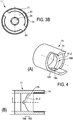
- FIG. 3A as a side view and in Fig. 3B as an end view of another Tangentialtschtechnik 11 is shown, which for a particularly preferred embodiment of a schematically in Fig. 1 Hand tool 100 shown is suitable.
- Fig. 3A and Fig. 3B show to a drive shaft 51 which is connected in a manner not shown, for example via a gear 106 with a motor 105 of a power tool 100 rotationally driven.
- a tool holder 40 or the like for receiving a tool, not shown, of the power tool 100 can be mounted in a manner not shown. Recognizable off Fig.
- 3A and 3B is the output shaft 31 by means of the drive shaft 51 and a Tangentialtschwerk 11 in a rotating and partially beating movement displaceable - this basically analogous to the above with reference to Fig. 2 explained principle.
- the tangential impact mechanism 11 has an output shaft 31 associated anvil 61 and a the drive shaft 51 associated hammer 71.
- the hammer 71 and the anvil 61 act in principle in the already principle with reference to Fig. 2 explained way together.
- FIG. 3A and Fig. 3B shown constructive realization of the hammer 71 under the action of a spring 81 and one of the views (A) and (B) of Fig. 3A as well as the Fig. 4 apparent slide guide 190 axially movable and twisting of the hammer 71 this is against the anvil 61 beatable.
- the anvil 61 is integrally connected to the output shaft 31.
- a spindle 21 is presently integrally connected to the drive shaft 51.
- the spring 81 is concentric with the spindle 21.
- the drive shaft 51, the spindle 21, the anvil 61 and the output shaft 31 are each arranged concentrically to the axis 2 to form the tangential impact mechanism 11.
- the spring 81 and the hammer 71 sit to move also concentric to the axis 2 on the spindle 21.
- the spring 81 is supported on the side of the drive shaft 31 from an annular stop 22, which sits at a shoulder between the spindle 21 and drive shaft 51.
- the spring 81 is supported on an end face 75 of the hammer 71 and biases it, or is able to move it in the direction of the axis 2 under positive guidance of the guide link 190. Both the end face 75 and the annular stop 22 for the spring 80 are shown schematically in FIG Fig. 2 shown.
- the slotted guide 190 for the preferred constructive realization of the tangential impactor 11 is further referred to the views (A) and (B) to illustrate the sections A - A and B - B of the Fig. 3A and referring to the Fig. 4 described.
- the slotted guide 190 has a first control contour 91.1 and a second control contour 91.2.
- the first control contour 91.1 indicates the course of a closed slide in the form of a groove 180 in the spindle 21.
- the groove 180 is threadedly introduced into the spindle 21 and has a basically V-shaped course, the -wie in view (B) of Fig. 3A evident- in plan symmetrical to the axis 2 extends.
- a first branch 181 of the V-shaped groove 180 and a second branch 182 of the V-shaped groove 180 are so far mirror-symmetrical and formed in principle gleichver signed.
- Each of the branches 181, 182 of the V-shaped groove 180 has a first portion 193 with a first pitch and a second portion 194 with a second pitch.
- first portion 193 with a first pitch and a second portion 194 with a second pitch.
- second portion 194 with a second pitch.
- a first pitch angle ⁇ of the first pitch measured with respect to the axis 2 of the spindle 21 for the slotted guide 190 is greater than a second pitch angle ⁇ of the second measured relative to the axis 2 Gradient in the second section 194.
- the first thread-like control contour 91.1 is assigned to the outer shell surface of the spindle 21 in the tangential impact mechanism 11, a second in Fig. 4 apparent control contour 91.2, which is introduced in a shell inside of the hammer 71.
- the second control contour 91.2 specifies the course of an open backdrop in the form of a tread.
- the second control contour 91.2 also has a first section 193 and a second section 194 provided with the same reference numerals for the sake of simplicity. Again, in the first section 193, a slope of the second control contour 91.2 measured with respect to the axis 2 is greater than a slope of the control contour 91.2 in the second section 194.
- first slope of the control contours 91.1, 91.2 is so large that approach the control contours 91.1, 91.2 in the course of a virtually paraxial course to the axis 2.
- the largest first pitch angle ⁇ in the first section 193 thus results at the top of the overall V-shaped course of the control contour 190 where the first branch 181 and the second branch 182 in collision at the height of the axis 2-- collide.
- the first slope of the control contour 91.1, 91.2 of the first section 193 asymptotically merges into the second slope of the second section 194.
- the first and second pitches - as exemplified by the pitch angles ⁇ , ⁇ - are the substantially unique different pitches of the control contour 190.
- first control contour 91.1 and the second control contour 91.2 are best obtained from view (A) of Fig. 3A.
- a sliding block 192 resting in the groove 180 of the spindle 21 as well as on the running surface 170 of the hammer 71 is forcibly guided.
- Similar to the already with reference to Fig. 2 explained principle is the hammer 71 while rotating the same axially along the axis 2 of the spindle 21 according to the specification of the slotted guide 190 movable.
- the bias of the spring 81 is thereby converted into kinetic energy of the hammer 71, which emits this as a torque peak when striking against the anvil 61. Beat it Hammer cam 74 and anvil cam 64 in the view (B) of Fig. 3A and Fig. 3B shown manner to each other.
- the positively driven sliding block 192 merges into the second section 194 of the slotted guide 190, ie into the region of the shallower second gradient with a gradient angle ⁇ .
- the sliding block 192 further passes through the groove 180 of the slotted guide 190 circumferentially of the spindle 21 and thus passes into the first portion 194 of the first branch 181 of the groove 180.
- the movement of the sliding block 192 then continues on the other side of the spindle 21 in basically the same way. In total, one stroke of the hammer 61 and the anvil 71 is thus carried out per half revolution of the spindle 21.
- a relatively high release torque of the hammer 71 against the anvil 61 is achieved by the steeper slope with first pitch angle ⁇ in the first section 193 of the slide guide 190.
- this comparatively high release torque can be achieved with comparatively low spring stiffness of the spring 81 and at comparatively low mass of the tangential impact device 11.
- the first section 193 of the slotted guide 190 primarily supports the formation of a comparatively high triggering torque.
- the second portion of the slotted guide 190 is primarily designed to build and transmit a comparatively high torque peak between the hammer 71 and the anvil 61.
- the transition between the second section 194 is comparatively narrow.
- an extension of the transitional area between the first pitch angle ⁇ and the second pitch angle ⁇ is held comparatively small against the extension of the sections 194, 193.
- This turns out - from views (B) of Fig. 3A and Fig. 4 apparent - in an approximately kink-like transition between the first portion 193 and the second portion 194 of the control contour 91.1 and the second control contour 91.2.
- At the transition of the hammer 71 is due to the shallower pitch of the control contour 91.1, 91.2 comparatively high speeds.
- pitch angles ⁇ , ⁇ these are selected as follows.
- a measured against the axis 2 and counterclockwise first pitch angle ⁇ is present rather above 135 °, ie between 135 ° and 180 ° in the course of the first portion 193 of the control contour 91.1, 91.2.
- a measured against the axis 2 and counterclockwise second pitch angle ⁇ of the second portion 194 is rather below 135 °, ie concretely approximately between an angle of 90 ° to 135 ° in the region of the second portion 194 of the control contour 91.1, 91.2.
- first pitch angle ⁇ asymptotically approaches the angle 180 ° with the course of the control contour 91.1, 91.2 to the axis 2.
- the control contour 91.1, 91.2 changes from the first pitch angle ⁇ into the second pitch angle ⁇ .
- the second pitch angle ⁇ approaches the angle 90 ° asymptotically.
- a comparatively smooth transition of the sliding block 192 between the branches 181, 182 -jeweils on the front and back of the spindle 21 and respectively at the tips of the V-shaped course of a control contour 91.1, 91.2 - is thus possible.
Abstract
Description
Die Erfindung betrifft eine Handwerkzeugmaschine. Die Handwerkzeugmaschine kann beispielsweise in Form eines Bohrhammers oder eines Schlagschraubers realisiert sein. Beispielsweise kann das Tangentialschlagwerk eine Schlagschraubbewegung der Abtriebswelle erzeugen. In dem Fall kann das Werkzeug in Form eines Schraubers gebildet sein, der in der Werkzeugaufnahme über die drehende und teilweise schlagende Bewegung der Abtriebswelle eine Schlagschraubbewegung ausführen kann. Das Tangentialschlagwerk wird üblicher Weise über einen Motor, gegebenenfalls unter Zwischenschaltung eines Getriebes, angetrieben. Die Hauptbestandteile eines kupplungartig aufgebauten Tangentialschlagwerks sind ein einer Antriebswelle der Kupplung zugeordneter Hammer und ein einer Abtriebswelle der Kupplung zugeordneter Amboss. Der Hammer kann sich gegen die Krafteinwirkung einer Feder axial unter Verdrehen desselben vom Amboss entfernen und anschließend wieder unter Verdrehen desselben -unter Krafteinwirkung der Feder beschleunigt- schlagend gegen den Amboss bewegt werden. Die Schlagbewegung erfolgt praktisch in Tangentialrichtung zur Drehbewegung. Die Drehbewegung und axiale Hin- und Herbewegung zur Ausführung eines Drehschlages sind durch eine Kulissenführung gekoppelt, so dass sich der Hammer letztlich unter Vorgabe der Kulissenführung zwangsgeführt bewegt. An einem einen Umkehrpunkt der Hin- und Herbewegung wird der Hammer vom Amboss ausgelöst. An einem anderen Umkehrpunkt der Hin- und Herbewegung führt der Hammer einen Drehschlag gegen den Amboss aus. Auf diese Weise kann der Hammer beispielsweise jede halbe Umdrehung praktisch in Tangentialrichtung zur Drehbewegung an den Amboss anschlagen und beim Drehschlag vergleichsweise hohe Drehmomentspitzen übertragen. Derartig hohe Drehmomentspitzen wären üblicherweise durch einen kontinuierlichen Drehantrieb der Abtriebswelle nicht erreichbar. Ein vorgenanntes Tangentialschlagwerk kann als ein resonantes Feder-Masse-System für einen vergleichsweise eng definierten Drehmomentbereich ausgelegt sein, innerhalb dem der eigentliche Betriebspunkt durch eine Antriebsdrehzahl des Antriebs für die Antriebswelle festgelegt ist. Der Betriebspunkt ist darüber hinaus durch ein Auslösemoment gekennzeichnet, bei dem der Hammer sich vom Amboss in Auslösestellung entkoppelt - d.h. das Auslösemoment bei Ausführung einer Trennung eines Eingriffs des Ambosses und des Hammers. Darüber hinaus ist der Betriebspunkt durch die beim Schlag übertragbare Drehmomentspitze gekennzeichnet. Maßgeblich dafür sind unter anderem das Trägheitsmoment des Hammers, die Federsteifigkeit der Feder und die Übertragungsfunktion der Kulissenführung, die letztlich durch eine Steuerkontur der Kulissenführung vorgebbar ist.The invention relates to a hand tool. The hand tool can be realized for example in the form of a hammer drill or impact wrench. For example, the Tangentialschlagwerk produce a Schlagschraubbewegung the output shaft. In that case, the tool may be in the form of a screwdriver which can carry out a striking screw movement in the tool holder via the rotating and partially striking movement of the output shaft. The Tangentialschlagwerk is usually powered by a motor, possibly with the interposition of a transmission. The main components of a clutch-like tangential impactor are a hammer associated with a drive shaft of the clutch and an anvil associated with an output shaft of the clutch. The hammer can be axially against the force of a spring while twisting the same from the anvil and then again while twisting the same-accelerated by the force of the spring-striking against the anvil to be moved. The impact movement is practically tangential to the rotational movement. The rotational movement and axial reciprocating motion for the execution of a rotary impact are coupled by a slotted guide, so that the hammer ultimately positively moves under specification of the slotted guide. At a reversal point of the reciprocation, the hammer is triggered by the anvil. At another reversal point of the reciprocation, the hammer makes a pivotal strike against the anvil. In this way, the hammer can strike, for example, every half turn virtually tangential to the rotational movement of the anvil and transmit relatively high torque peaks during the rotary impact. Such high torque peaks would usually not be achievable by a continuous rotary drive of the output shaft. One The aforementioned Tangentialschlagwerk can be designed as a resonant spring-mass system for a comparatively narrowly defined torque range within which the actual operating point is determined by a drive speed of the drive for the drive shaft. The operating point is also characterized by a triggering moment, in which the hammer decouples from the anvil in the release position - ie the release torque when performing a separation of an engagement of the anvil and the hammer. In addition, the operating point is characterized by the torque transmittable at impact. Decisive for this are, inter alia, the moment of inertia of the hammer, the spring stiffness of the spring and the transfer function of the slotted guide, which is ultimately predetermined by a control contour of the slotted guide.
Im Rahmen üblicher Anwendungen weist ein Tangentialschlagwerk ein vergleichsweise geringes Auslösemoment auf, das mittels einer vergleichsweise geringen Federsteifigkeit erreicht wird. Ein hohe Drehmomente erforderndes Bohren von z. B. tiefen Löchern mit großen Durchmessern ist unter Nutzung eines solchen üblichen Tangentialschlagwerks nur bedingt möglich.Within the scope of customary applications, a tangential striking device has a comparatively low release torque, which is achieved by means of a comparatively low spring rigidity. High torques requiring drilling of z. B. deep holes with large diameters is only partially possible using such a conventional Tangentialschlagwerks.
Wünschenswert wäre es, ein Tangentialschlagwerk auch für Anwendungen mit vergleichsweise hohen Drehmomentanforderungen auszulegen. Ein einfaches Hochskalieren der Auslegungsparameter eines üblichen Tangentialschlagwerks führt hier nicht zum Ziel, da dies regelmäßig mit einer Erhöhung der Körpermassen des Tangentialschlagwerks einher geht. Bei einer Werkzeugmaschine der eingangs genannten Art würde dies zu einer Verschlechterung der Handhabbarkeit führen.It would also be desirable to design a tangential impactor for applications with comparatively high torque requirements. A simple scaling up of the design parameters of a standard tangential impactor does not lead to the goal here, since this is regularly accompanied by an increase in the body masses of the tangential impactor. In a machine tool of the type mentioned, this would lead to a deterioration of the handling.
Die Aufgabe betreffend die Handwerkzeugmaschine wird durch die Erfindung mit einer Handwerkzeugmaschine der eingangs genannten Art gelöst, bei der erfindungsgemäß vorgesehen ist, dass die Kulissenführung eine gewindeartige Steuerkontur aufweist, die in einem ersten Abschnitt eine erste Steigung und in einem zweiten Abschnitt eine zweite Steigung aufweist, wobei die erste und zweite Steigung unterschiedlich sind.The task relating to the power tool is achieved by the invention with a hand tool of the type mentioned, is provided in accordance with the invention that the slide guide has a thread-like control contour having a first slope in a first section and a second slope in a second slope, wherein the first and second slopes are different.
Bevorzugt ist ein in Bezug auf eine Achse eines zylindrischen Körpers für die Kulissenführung gemessener erster Steigungswinkel α der ersten Steigung grösser als ein in Bezug auf die Achse gemessener zweiter Steigungswinkel β der zweiten Steigung. Die Steigungen haben insbesondere gleiches Vorzeichen, d. h. die Abschnitte sind Teil eines einzigen gewindeartigen Verlaufs der Steuerkontur. In einer besonders bevorzugten Weiterbildung kann dazu vorgesehen sein, dass der erste Abschnitt einen ambossnahen Abschnitt und der zweite Abschnitt einen ambossfernen Abschnitt der Steuerkontur bildet und die erste Steigung grösser als die zweite Steigung ist. Insbesondere können die erste und die zweite Steigung einzige wesentlich unterschiedliche Steigungen der Steuerkontur sein. D.h. bis auf einen möglichst kontinuierlichen Übergangsbereich gibt es praktisch nur den ersten und zweiten Abschnitt mit wesentlich unterschiedlichen Steigungen. Bevorzugt grenzen der erste und zweite Abschnitt unmittelbar aneinander an.Preferably, a first pitch angle α of the first pitch measured with respect to an axis of a cylindrical body for the link guide is greater than a second pitch angle β of the second pitch measured with respect to the axis. The slopes have in particular the same sign, ie the sections are part of a single thread-like course of the control contour. In a particularly preferred Further development may be provided that the first section forms an anvil-proximal section and the second section forms an anvil-distant section of the control contour and the first gradient is greater than the second gradient. In particular, the first and the second pitch may be only significantly different slopes of the control contour. That is, except for a continuous transition region as possible, there are practically only the first and second sections with significantly different gradients. Preferably, the first and second portions directly adjoin one another.
Die Erfindung geht von der Überlegung aus, dass ein Tangentialschlagwerk für eine anwenderfreundliche und vergleichsweise gewichtsarme Handwerkzeugmaschine ein Federsystem mit vergleichsweise geringer Federsteifigkeit aufweisen sollte. Ausgehend davon wurde darüber hinaus erkannt, dass dennoch ein vergleichsweise hohes Auslösemoment erreichbar ist, wenn eine Kulissenführung -insbesondere in einem dem Schlag zugeordneten, hier z.B. ersten, Abschnitt- vorzugsweise geeignet steil gestaltet ist. Auch wurde erkannt, dass zur Übertragung einer vergleichsweise hohen Drehmomentspitze bei einem Schlag zwischen Hammer und Amboss eine Kulissenführung -insbesondere in einem der Auslösung von Hammer und Amboss zugeordneten, hier z.B. zweiten, Abschnittvorzugsweise geeignet flach ausgelegt wird. Grundsätzlich hat die Erfindung erkannt, dass ein dem Schlag zugeordneter erster Abschnitt und ein der Auslösung zugeordneter zweiter Abschnitt mit einer unterschiedlichen ersten und zweiten Steigung einer gewindeartigen Steuerkontur versehen werden kann.The invention is based on the consideration that a Tangentialschlagwerk for a user-friendly and comparatively low-weight hand tool machine should have a spring system with relatively low spring stiffness. On the basis of this, it has additionally been recognized that nevertheless a comparatively high release torque can be achieved if a slotted guide, in particular in an impact associated with, here e.g. first, section is preferably designed steeply. It has also been recognized that in order to transmit a comparatively high torque peak in a hammer to anvil stroke, a slotted guide, particularly in one of the hammer and anvil firing, here e.g. second, section preferably suitably flat. In principle, the invention has recognized that a first portion assigned to the impact and a second portion assigned to the triggering can be provided with a different first and second pitch of a thread-like control contour.
Im Unterschied zu einer üblichen Steuerkontur -z.B. einer auf einer Spindel angebrachten gleichförmigen gewindeartigen Steuerkontur mit konstanter Steigung über den gesamten Verlauf der Steuerkontur - sieht das Konzept der Erfindung also eine Kulissenführung mit gewindeartiger Steuerkontur vor, die eine in angepasster Weise variierte Steigung aufweist. Diese in oben genannter Weise angepasste Steuerkontur weist in einem der Drehmomentübertragung zugeordneten ersten Abschnitt eine andere Steigung auf als in einem der Auslösung von Hammer und Amboss zugeordneten zweiten Abschnitt. Vorzugsweise kann die Kulissenführung darüberhinaus eine grundsätzlich V-artig --auch doppelgewindeartig-- ausgeführte Steuerkontur aufweisen. Jedoch ist diese in Abgrenzung zu einer vorbekannten Steuerkontur mit einem einzigen durchgehend gleichgerichteten Gewindeverlauf in einem V-Schenkel versehen, der zudem in einem ersten Abschnitt des V-Schenkels eine erste Steigung und in einem zweiten davon unterschiedlichen Abschnitt des V-Schenkels eine zweite unterschiedliche Steigung gleichen Vorzeichens aufweist.In contrast to a conventional control contour-for example, a uniform thread-like control contour with constant pitch over the entire course of the control contour, which is mounted on a spindle, the concept of the invention therefore provides a slotted guide with a thread-like control contour which has a slope that is varied in an adapted manner. This control contour adapted in the above-mentioned manner has a different pitch in a first section assigned to the torque transmission than in a second section assigned to triggering of the hammer and anvil. Preferably, the slide guide can also have a basically V-like - even double-threaded - executed control contour. However, this is in contrast to a previously known control contour with a single continuously rectified thread path in a V-leg provided, which also has a first pitch in a first portion of the V-leg and a second different pitch in a second different portion of the V-leg has the same sign.
Mit einer derart angepassten gewindeartigen Steuerkontur der Kulissenführung kann ein vergleichsweise guter Schlag als auch ein vergleichsweise hohes Auslösemoment erreicht werden; dies vorteilhaft ohne dass die Masse des Tangentialschlagwerks erhöht werden müsste. Insbesondere kann eine Federsteifigkeit dennoch vergleichsweise gering gehalten werden.With such a matched thread-like control contour of the guide slot, a relatively good impact as well as a relatively high release torque can be achieved; this is advantageous without the mass of Tangentialschlagwerks should be increased. In particular, a spring stiffness can nevertheless be kept relatively low.
Weitere vorteilhafte Weiterbildungen der Erfindung sind den Unteransprüchen zu entnehmen und geben im Einzelnen vorteilhafte Möglichkeiten an, das oben erläuterte Konzept im Rahmen der Aufgabenstellung, sowie hinsichtlich weiterer Vorteile zu realisieren.Further advantageous developments of the invention can be found in the dependent claims and indicate in detail advantageous possibilities to realize the above-described concept within the scope of the task, as well as with regard to further advantages.
Bevozugt ist der Amboss einstückig mit der Abtriebswelle und die Spindel einstückig mit der Antriebswelle verbunden. Bevorzugt ist die Kulissenführung auf einem zylindrischen Körper wie einer Welle -z.B. Spindel- oder einem Hohlkörper gebildet; beispielsweise auf einer Aussenseite oder einer Innenseite des zylindrischen Körpers. Diese Massnahmen -einzeln oder in Kombination- führen zu einem besonders kompakten und stabilen Tangentialschlagwerk.Bevozugt the anvil is integral with the output shaft and the spindle integrally connected to the drive shaft. Preferably, the slotted guide is on a cylindrical body, such as a shaft - e.g. Spindle or a hollow body formed; for example, on an outside or inside of the cylindrical body. These measures - individually or in combination - lead to a particularly compact and stable tangential impact mechanism.
Bevorzugt weist die Kulissenführung eine erste Steuerkontur auf einer Spindel zwischen Antriebswelle und Abtriebswelle auf. Alternativ, bevorzugt zusätzlich, weist die Kulissenführung eine zweite Steuerkontur auf einer Mantelinnenseite des Hammers auf. Insbesondere durch das Zusammenspiel der vorgenannten ersten und zweiten Steuerkontur in einer bevorzugten Kulissenführung lässt sich eine axiale und drehende Bewegung von Hammer gegen Amboss zur Ausführung einer Dreh-Schlagbewegung mit Vorteil realisieren.Preferably, the slotted guide on a first control contour on a spindle between the drive shaft and output shaft. Alternatively, preferably in addition, the slotted guide has a second control contour on a shell inside of the hammer. In particular, by the interaction of the aforementioned first and second control contour in a preferred slotted guide can be an axial and rotary movement of hammer against anvil for performing a rotary-striking movement realize with advantage.
Unter Weiterbildung kann nur die erste Steuerkontur oder nur die zweite Steuerkontur der Kulissenführung jeweils einen ersten Abschnitt mit der ersten Steigung und einen zweiten Abschnitt mit der zweiten unterschiedlichen Steigung aufweisen. Es kann in einer Abwandlung auch die erste Steuerkontur und die zweite Steuerkontur der Kulissenführung jeweils einen ersten Abschnitt mit der ersten Steigung und einen zweiten Abschnitt mit der zweiten unterschiedlichen Steigung aufweisen.Under development, only the first control contour or only the second control contour of the slotted guide each having a first portion with the first slope and a second portion with the second different pitch. In a modification, it is also possible for the first control contour and the second control contour of the sliding guide each to have a first section with the first gradient and a second segment with the second differential gradient.
Vorzugsweise bildet (insbesondere jeweils) der erste Abschnitt einen ambossnahen Abschnitt und der zweite Abschnitt einen ambossfernen Abschnitt der Steuerkontur. Die erste Steigung ist bevorzugt grösser als die zweite Steigung. Insbesondere ist ein in Bezug auf eine Achse eines zylindrischen Körpers für die Kulissenführung gemessener erster Steigungswinkel α der ersten Steigung grösser als ein in Bezug auf die Achse gemessener zweiter Steigungswinkel β der zweiten Steigung. In besonders vorteilhafter Weise wird mit dem Tangentialschlagwerk ein erhöhtes Auslösemoment erreichbar und das Tangentialschlagwerk ist dennoch in der Lage, eine vergleichsweise hohe Drehmomentspitze zu übertragen, d. h. einen guten Schlag auszuführen. Die Steuerkontur gewährleistet eine besonders sichere und verlustfreie Kraftübertragung in dem als Kupplung wirkenden Tangentialschlagwerk. Das Tangentialschlagwerk eignet sich in besonders bevorzugter Weise auch zur Ausführung hohe Drehmomente erfordernder Arbeiten.The first section preferably forms (in particular in each case) an anvil-proximal section and the second section forms an anvil-distant section of the control contour. The first slope is preferably greater than the second slope. In particular, a first pitch angle α of the first pitch measured with respect to an axis of a cylindrical body for the link guide is larger than a one measured with respect to the axle second pitch angle β of the second pitch. In a particularly advantageous manner, an increased release torque can be achieved with the tangential impactor, and the tangential impactor is nevertheless able to transmit a comparatively high torque peak, ie to execute a good impact. The control contour ensures a particularly safe and lossless power transmission in acting as a coupling Tangentialschlagwerk. The Tangentialschlagwerk is particularly suitable for carrying out high-torque-requiring work.
Es hat sich als besonders vorteilhaft erwiesen, dass die erste und zweite Steigung im Wesentlichen einzige Steigungen der Steuerkontur sind und der erste und zweite Abschnitt unmittelbar aneinander angrenzen. Dies führt zu einer vergleichsweise einfachen Ausführung der Steuerkontur. Grundsätzlich kann darüber hinaus zwischen dem ersten und zweiten Abschnitt ein weiterer Abschnitt vorgesehen sein, der als Übergangsabschnitt mit einer graduellen Steigungsanpassung versehen ist oder eine zwischen der ersten und zweiten Steigung liegenden konstanten Wert aufweist.It has proved to be particularly advantageous that the first and second pitches are substantially single pitches of the control contour and the first and second portions are directly adjacent to each other. This leads to a comparatively simple design of the control contour. In principle, moreover, between the first and second section, a further section may be provided, which is provided as a transition section with a gradual slope adjustment or has a constant value lying between the first and second pitch.
In einer besonders vorteilhaften Weiterbildung ist die Steuerkontur -bevorzugt eine erste Steuerkontur- von einer geschlossenen Kulisse der Kulissenführung gebildet. In besonders bevorzugter Konstruktion ist eine geschlossene Kulisse in Form einer Nut (z. B. mit U-förmigem Querschnitt) gebildet, wobei in der Nut ein mit dem Hammer zwangsgeführt verbundener Kulissenstein bewegbar ist.In a particularly advantageous development, the control contour-preferably a first control contour-is formed by a closed link of the slotted guide. In a particularly preferred construction, a closed slot is formed in the form of a groove (eg, with a U-shaped cross-section), wherein a sliding block positively connected to the hammer can be moved in the slot.
In einer anderen besonders vorteilhaften Weiterbildung ist die Steuerkontur von einer offenen Kulisse der Kulissenführung gebildet. Besonders bevorzugt ist die zweite Steuerkontur von einer offenen Kulisse der Kulissenführung gebildet ist. In besonders bevorzugter Konstruktion ist eine offene Kulisse in Form einer Lauffläche (mit einem flachen Querschnitt) gebildet, wobei an der Lauffläche ein mit dem Hammer zwangsgeführt verbundener Kulissenstein bewegbar ist.In another particularly advantageous embodiment, the control contour is formed by an open link of the slide guide. Particularly preferably, the second control contour is formed by an open link of the slotted guide. In a particularly preferred construction, an open slide in the form of a running surface (with a flat cross-section) is formed, wherein on the running surface a forcibly guided connected to the hammer sliding block is movable.
In einer besonders bevorzugten -auch anhand einer Ausführungsform erläuterten-Weiterbildung ist die Kulissenführung durch ein Zusammenspiel einer geschlossenen Kulisse auf einer Spindel zwischen Antriebswelle und Abtriebswelle und einer offenen Kulisse auf einer Mantelinnenseite des Hammers gebildet. Es kann alternativ auch die Kulissenführung durch ein Zusammenspiel einer geschlossenen Kulisse auf einer Mantelinnenseite des Hammers und einer offenen Kulisse auf einer Spindel zwischen Antriebswelle und Abtriebswelle gebildet sein. Diese Arten einer Kulissenführung aus einer Kombination einer geschlossenen und einer offenen Kulisse haben sich besonders bewährt.In a particularly preferred training also explained with reference to an embodiment, the link guide is formed by an interaction of a closed gate on a spindle between the drive shaft and output shaft and an open gate on a shell inside of the hammer. It can alternatively also the slide guide by an interaction of a closed gate on a shell inside of the hammer and an open gate on a spindle between the drive shaft and Be formed output shaft. These types of slotted guide from a combination of a closed and an open backdrop have proven particularly useful.
Im Rahmen einer vorgenannten besonders bevorzugten Weiterbildung ist die Steuerkontur in Form einer Nut der Lauffläche gebildet, wobei ein an der Steuerkontur zwangsgeführter Kulissenstein bewegbar ist. Grundsätzlich kann die Steuerkontur auch invers dazu gebildet sein, z. B. mit einem Steg, auf oder an dem ein Kulissenstein zwangsgeführt ist. Grundsätzlich kann eine Steuerkontur einer Kulissenführung zur Realisierung einer geeigneten Übertragungsfunktion mit zwei unterschiedlichen Steigungen in einer den konstruktiven Erfordernissen angepassten Art und Weise verwirklicht sein.In the context of an aforementioned particularly preferred development, the control contour is formed in the form of a groove of the tread, wherein a force-guided on the control contour sliding block is movable. In principle, the control contour can also be formed inversely thereto, for. B. with a web on or on which a sliding block is forced. In principle, a control contour of a slotted guide for realizing a suitable transfer function with two different gradients can be realized in a manner adapted to the design requirements.
Vorzugsweise bildet der erste Abschnitt einen ambossnahen Abschnitt und der zweite Abschnitt einen ambossfernen Abschnitt der Steuerkontur, wobei die erste Steigung bevorzugt grösser als die zweite Steigung ist. Mit anderen Worten ist die der Übertragung der Drehmomentspitze beim Schlag zugeordnete erste Steigung grösser als die der Auslösung von Hammer und Amboss zugeordnete zweite Steigung der Steuerkontur, insbesondere bei einer auf der Spindel befindlichen ersten Steuerkontur.The first section preferably forms an anvil-proximal section and the second section forms an anvil-distant section of the control contour, wherein the first gradient is preferably greater than the second gradient. In other words, the first pitch assigned to the transmission of the torque peak during impact is greater than the second pitch of the control contour assigned to the triggering of the hammer and anvil, in particular in the case of a first control contour located on the spindle.
Im Rahmen einer derartigen Weiterbildung wurde erkannt, dass eine Drehmomentspitze mit vergleichsweise hohem Betrag übertragbar ist, wenn ein möglichst großer Teil, insbesondere die gesamte Rotationsenergie des Hammers in Schlagenergie des Drehschlags (auch Tangentialschlag genannt) transformiert wird, d. h. in ein Drehmoment transformiert wird. Dies kann durch eine gegen eine Achse gemessene vergleichsweise flache Auslegung der Steuerkontur unterstützt werden. Im Rahmen einer weiteren Weiterbildung wurde erkannt, dass ein Auslösemoment zwischen Amboss und Hammer vergleichsweise hoch auslegbar ist. Dies kann durch eine gegen eine Achse gemessene vergleichsweise steile Auslegung der Steuerkontur unterstützt werden.In the context of such a development has been recognized that a torque peak with a relatively high amount is transferable when the largest possible part, in particular the entire rotational energy of the hammer in impact energy of the rotary shock (also called tangential impact) is transformed, d. H. is transformed into a torque. This can be supported by a comparatively flat design of the control contour measured against an axis. As part of a further development has been recognized that a release torque between the anvil and hammer is relatively high interpretability. This can be supported by a comparatively steep design of the control contour measured against an axis.
Vorzugsweise steigt die erste Steigung im ersten ambossnahen Abschnitt an. Der Anstieg kann graduell umgesetzt sein. Der erste Abschnitt mit grösserer Steigung kann auch in Form eines ersten ambossnahen Abschnitts mit konstanter Steigung ausgeführt sein, die grösser als die zweite Steigung im zweiten ambossfernen Abschnitt ist. Die zweite Steigung der Steuerkontur ist vergleichsweise gering. In diesem Fall kann der Steigungsverlauf im zweiten Abschnitt graduell abnehmen. Der zweite Abschnitt kann jedoch auch vergleichsweise einfach als Abschnitt konstanter zweiter Steigung ausgelegt sein, die geringer ist als eine erste Steigung im ersten Abschnitt. Insbesondere kann ein Steigungsverlauf im Übergang vom ersten zum zweiten Abschnitt graduell oder abgestuft oder als einfache Stufe zwischen der ersten und zweiten Steigung ausgeführt sein.Preferably, the first slope increases in the first region near the anvil. The increase can be implemented gradually. The first section of greater pitch may also be in the form of a first anvil-proximal section of constant pitch greater than the second pitch in the second anvil-distal section. The second slope of the control contour is comparatively small. In this case, the pitch curve in the second section may gradually decrease. However, the second section can also be designed relatively simply as a section of constant second pitch, which is less than one first climb in the first section. In particular, a gradient curve in the transition from the first to the second section can be made gradual or graduated or as a simple step between the first and second gradient.
Insbesondere ist vorgesehen, dass in Eingriffstellung des Ambosses und des Hammers zur Ausführung eines Tangentialschlages ein mit dem Hammer zwangsführend verbundener Kulissenstein im ersten Abschnitt der Steuerkontur angeordnet ist. Dadurch wird vorteilhaft ausgeschlossen, dass eine Übertragung einer Drehmomentspitze durch eine Widerstand bewirkende Kraftaufnahme im zweiten Abschnitt mit geringerer zweiter Steigung begrenzt wird. Vielmehr ist gewährleistet, dass der Kulissenstein im Bereich der vergleichsweise grösseren ersten Steigung die Übertragung praktisch der vollen Rotationsenergie des Hammers als Drehmoment auf den Amboss ermöglicht und nicht entgegen wirkt.In particular, it is provided that in the engaged position of the anvil and the hammer for the execution of a Tangentialschlag a positively forcibly connected to the hammer sliding block in the first section of the control contour is arranged. This advantageously prevents a transfer of a torque peak being limited by a resistance-causing force absorption in the second section with a lesser second gradient. Rather, it is ensured that the sliding block in the range of comparatively larger first slope allows the transmission of virtually the full rotational energy of the hammer as torque to the anvil and does not counteract.
Zur Ausführung eines Tangentialschlags befindet sich der Amboss und der Hammer bevorzugt in vollständiger Eingriffstellung. In einem den Drehschlag ausführenden Umkehrpunkt der Hin- und Herbewegung des Hammers weist der Amboss und der Hammer einen Eingriffsbereich auf, der beispielsweise durch die Länge von Anschlagmitteln vorgegeben sein kann. Vorteilhaft ist vorgesehen, dass der erste Abschnitt insbesondere grösserer Steigung eine axiale Erstreckung aufweist, die wenigstens 20 % der axialen Erstreckung des Eingriffsbereichs ausmacht. Dadurch ist sichergestellt, dass wenigstens auf den restlichen 20 % der axialen Erstreckung des Eingriffsbereichs eine vorteilhaft grössere erste Steigung vorliegt, die eine Übertragung von besonders hohen Drehmomentspitzen erlaubt. Tendenziell wird das Ergebnis beim Schlag verbessert, je größer die axiale Erstreckung des ersten Abschnitts ist. Vorteilhaft macht die axiale Erstreckung des Abschnitts wenigstens 20 % der axialen Erstreckung des Eingriffsbereichs aus oder entspricht in etwa der Erstreckung des Eingriffsbereichs ohne diese jedoch zu übersteigen.To perform a Tangentialschlags the anvil and the hammer is preferably in fully engaged position. In a rotational turning point of the reciprocating motion of the hammer, the anvil and the hammer have an engaging portion which may be predetermined by the length of stopper means, for example. Advantageously, it is provided that the first section, in particular of a larger pitch, has an axial extent which makes up at least 20% of the axial extent of the engagement area. This ensures that at least on the remaining 20% of the axial extent of the engagement region an advantageously larger first slope is present, which allows a transmission of particularly high torque peaks. The result tends to be improved in the impact, the greater the axial extent of the first section. Advantageously, the axial extension of the section makes up at least 20% of the axial extent of the engagement region or approximately corresponds to the extent of the engagement region without, however, exceeding it.
Auch hat es sich als vorteilhaft erwiesen, dass wenigstens in Auslösestellung des Ambosses und des Hammers zur Ausführung einer Trennung eines Eingriffs derselben ein mit dem Hammer zwangsführend verbundener Kulissenstein im zweiten Abschnitt der Steuerkontur angeordnet ist. Auf diese Weise wird sichergestellt, dass der Kulissenstein in Anbetracht der geringeren zweiten Steigung der Kulissenführung nur ein hohes Auslösemoment erlaubt.Also, it has proven to be advantageous that at least in the release position of the anvil and the hammer to perform a separation of an engagement of the same a forcibly connected to the hammer sliding block in the second section of the control contour is arranged. In this way it is ensured that the sliding block allows only a high release torque in view of the lower second slope of the slotted guide.
Ein Anschlagmittel ist beim Amboss und/oder Hammer vorzugsweise in Form von wenigstens einem Nocken gebildet. Als besonders vorteilhaft haben sich zwei Nocken erwiesen. Die Nocken sind vorteilhaft an einem Ringumfang des Ambosses bzw. des Hammers gebildet. Der Ringumfang kann kopfseitig oder seitlich vom Amboss und/oder Hammer angeordnet sein. Die Weiterbildung mit zwei Nocken erlaubt mit geeigneter Anpassung der Steuerkontur ein Auslösen bzw. tangentiales Anschlagen von Hammer und Amboss bei jeder halben Umdrehung. Unter weiterer geeigneter Anpassung der Kulissenführung können auch mehr als zwei Nocken beispielsweise in Form eines Zahnkranzes vorgesehen sein. Insbesondere kann dies eine Drehbewegung auf einen Bruchteil einer vollen Umdrehung des Hammers begrenzen.A stop means is formed in the anvil and / or hammer, preferably in the form of at least one cam. Particularly advantageous two cams have proven. The cams are advantageous on a ring circumference of the anvil or the Hammer formed. The ring circumference can be arranged on the head side or laterally of the anvil and / or hammer. The development with two cams allows with appropriate adaptation of the control contour a triggering or tangential striking of the hammer and anvil at every half turn. With further suitable adaptation of the slotted guide more than two cams may be provided, for example in the form of a ring gear. In particular, this may limit a rotational movement to a fraction of a full revolution of the hammer.
Im Rahmen einer besonders bevorzugten Verwendung des Tangentialschlagwerks lässt sich eine Handwerkzeugmaschine in Form eines Bohrhammers ausbilden. Vorzugsweise ist das Tangentialschlagwerk ausgebildet, die Funktion einer Rutschkupplung auszuführen. In dieser Verwendung kann das Tangentialschlagwerk vorzugsweise auch außer Resonanz des entsprechenden Feder-Masse-Systems betrieben werden. Die zweite Steigung im zweiten ambossfernen Abschnitt der Steuerkontur ist vorzugsweise derart ausgeführt, dass das Tangentialschlagwerk ein besonders hohes Auslösemoment aufweist, um den normalen Bohrbetrieb des Bohrhammers zu erlauben, d. h. im normalen Bohrbetrieb eben nicht auszulösen.Within the scope of a particularly preferred use of the tangential impact tool, a hand tool machine in the form of a rotary hammer can be formed. Preferably, the Tangentialschlagwerk is designed to perform the function of a slip clutch. In this use, the tangential impactor may also preferably be operated out of resonance of the corresponding spring-mass system. The second slope in the second anvil distant portion of the control contour is preferably designed such that the tangential impactor has a particularly high release torque to allow the normal drilling operation of the hammer drill, d. H. in normal drilling operation just do not trigger.
In einer dazu abgewandelten Weiterbildung einer Verwendung hat es sich als vorteilhaft erwiesen, die Handwerkzeugmaschine in Form eines Schlagschraubers auszubilden. Bei dieser Weiterbildung ist das Tangentialschlagwerk ausgebildet, die Funktion einer Schlagschraubbewegung auszuführen. Hier hat es sich als besonders vorteilhaft erwiesen, das Tangentialschlagwerk für einen resonanten Betrieb des damit verbundenen Feder-Masse-Systems auszulegen. Dies kann für einen definierten vergleichsweise begrenzten Drehmomentbereich geschehen. Insbesondere ist die erste Steigung im ersten ambossnahen Abschnitt mit einem vergleichsweise hohen Wert ausgeführt, um einen besonders hohen Drehmomentspitzenübertrag beim Drehschlag zwischen Hammer und Amboss zu erreichen.In a modified development of a use, it has proved to be advantageous to form the power tool in the form of a striking screwdriver. In this development, the Tangentialschlagwerk is designed to perform the function of a Schlagschraubbewegung. Here, it has proven to be particularly advantageous to interpret the Tangentialschlagwerk for a resonant operation of the associated spring-mass system. This can be done for a defined comparatively limited torque range. In particular, the first slope in the first anvil-proximal portion is designed with a comparatively high value in order to achieve a particularly high torque peak transfer during the rotary impact between the hammer and the anvil.
Eine Anpassung der Steuerkontur gemäss dem Konzept der Erfindung ist insbesondere für die beiden vorgenannten Fälle einer Verwendung besonders vorteilhaft. Darüber hinaus lassen sich die vorgenannten Fälle einer Verwendung auch miteinander kombinieren durch eine optimierte Anpassung sowohl des ersten Abschnitts mit vergleichsweise grösserer Steigung als auch des zweiten Abschnitts mit vergleichsweise geringerer Steigung. Insgesamt wird die Ausführung eines bedarfsangepassten Tangentialschlagwerks möglich, das den Übertrag hoher Drehmomentspitzen beim Drehschlag einerseits und den Betrieb bei hohen Drehmomentanforderungen unterhalb eines Auslösemoments des Tangentialschlagwerks erlaubt. Insbesondere lässt sich ein Auslösemoment des Tangentialschlagwerks durch Vergrößern der ersten Steigung im ersten ambossnahen Abschnitt vergleichsweise hoch gestalten, so dass sich das Tangentialschlagwerk praktisch wie eine Rutschkupplung verhält. Dennoch ist eine vergleichsweise gute Drehmomentübertragung im ambossfernen Abschnitt gewährleistet.An adaptation of the control contour according to the concept of the invention is especially advantageous for the two aforementioned cases of use. In addition, the aforementioned cases of use can also be combined with one another by an optimized adaptation of both the first section with a comparatively larger pitch and the second section with a comparatively smaller pitch. Overall, the execution of a demand-matched Tangentialschlagwerks possible, the transfer of high torque peaks in the rotary impact on the one hand and the operation at high torque requirements below a tripping torque of the tangential impact allowed. In particular, a triggering moment of the tangential impactor can be made comparatively high by increasing the first pitch in the first region near the anvil so that the tangential impactor behaves virtually like a friction clutch. Nevertheless, a comparatively good torque transmission in the anvil distant section is ensured.
Ausführungsbeispiele der Erfindung werden nun nachfolgend anhand der Zeichnungen beschrieben. Diese sollen die Ausführungsbeispiele nicht nofiniendigerweise maßstäblich darstellen, vielmehr sind die Zeichnungen, wo zur Erläuterung dienlich, in schematisierter und/oder leicht verzerrter Form ausgeführt. Im Hinblick auf Ergänzungen der aus der Zeichnung unmittelbar erkennbaren Lehren wird auf den einschlägigen Stand der Technik verwiesen. Dabei ist zu berücksichtigen, dass vielfältige Modifikationen und Änderungen betreffend die Form und das Detail einer Ausführungsform vorgenommen werden können, ohne von der allgemeinen Idee der Erfindung abzuweichen. Die in der Beschreibung, in der Zeichnung sowie in den Ansprüchen offenbarten Merkmale der Erfindung können sowohl einzeln als auch in beliebiger Kombination für die Weiterbildung der Erfindung wesentlich sein. Zudem fallen in den Rahmen der Erfindung alle Kombinationen aus zumindest zwei der in der Beschreibung, der Zeichnung und/oder den Ansprüchen offenbarten Merkmale. Die allgemeine Idee der Erfindung ist nicht beschränkt auf die exakte Form oder das Detail der im folgenden gezeigten und beschriebenen bevorzugten Ausführungsformen oder beschränkt auf einen Gegenstand, der eingeschränkt wäre im Vergleich zu dem in den Ansprüchen beanspruchten Gegenstand. Bei angegebenen Bemessungsbereichen sollen auch innerhalb der genannten Grenzen liegende Werte als Grenzwerte offenbart und beliebig einsetzbar und beanspruchbar sein.Embodiments of the invention will now be described below with reference to the drawings. These are not intended to scale the embodiments nofiniendlichlich, but the drawings, where appropriate for explanation, executed in a schematized and / or slightly distorted form. With regard to additions to the teachings directly recognizable from the drawing reference is made to the relevant prior art. It should be noted that various modifications and changes may be made in the form and detail of an embodiment without departing from the general idea of the invention. The disclosed in the description, in the drawing and in the claims features of the invention may be essential both individually and in any combination for the development of the invention. In addition, all combinations of at least two of the features disclosed in the description, the drawings and / or the claims fall within the scope of the invention. The general idea of the invention is not limited to the exact form or detail of the preferred embodiments shown and described below or limited to an article which would be limited in comparison with the subject matter claimed in the claims. For the given design ranges, values within the stated limits should also be disclosed as limit values and be arbitrarily usable and claimable.
Weitere Vorteile, Merkmale und Einzelheiten der Erfindung ergeben sich aus der nachfolgenden Beschreibung der bevorzugten Ausführungsformen sowie anhand der Zeichnung; im Einzelnen zeigen die Zeichnungen in:
-
Fig. 1 eine schematische Darstellung einer Handwerkzeugmaschine -vorliegend als ein Bohrhammer oder ein Schlagschrauber- mit einem Tangentialschlagwerk; -
Fig. 2 eine schematische Darstellung des Tangentialschlagwerks der Handwerkzeugmaschine derFig. 1 , wobei der Hammer und der Amboss des Tangentialschlagwerks in der Art eine Explosionsdarstellung vergleichsweise weit auseinander gezogen sind, um den Verlauf der gewindeartigen Steuerkontur der Kulissenführung darzustellen - zur Erläuterung des Konzepts der Erfindung ist eine Kulissenführung mit einer einfachen Kulisse einer gewindeartigen Steuerkontur mit einer ersten und zweiten Steigung gezeigt, die gleiches Vorzeichen haben und vom Betrag unterschiedlich sind; -
Fig. 3A eine detaillierte Darstellung einer bevorzugten konstruktiven Realisierung eines Tangentialschlagwerks für eine besonders bevorzugte Ausführungsform einer Handwerkzeugmaschine in einer Seitenansicht (C) sowie in zwei Schnittansichten (B) und (A) dazu; -
Fig. 3B eine Stirnansicht auf die Seitenansicht derFig. 3A (C) ; -
Fig.4 in Ansicht (A) eine perspektivische Ansicht auf den Hammer für die konstruktive Realisierung des Tangentialschlagwerks derFig. 3A, Fig. 3B und in Ansicht (B) eine Schnittansicht des Hammers der Ansicht (A).
-
Fig. 1 a schematic representation of a hand tool - present as a hammer drill or impact wrench - with a Tangentialschlagwerk; -
Fig. 2 a schematic representation of the tangential impact of the power tool of theFig. 1 , with the hammer and the anvil of the Tangential impact in the manner of an exploded view are drawn comparatively far apart to illustrate the course of the thread-like control contour of the slotted guide - to illustrate the concept of the invention, a slotted guide is shown with a simple backdrop of a thread-like control contour with a first and second pitch, have the same sign and are different from the amount; -
Fig. 3A a detailed representation of a preferred structural realization of a Tangentialschlagwerks for a particularly preferred embodiment of a hand tool in a side view (C) and in two sectional views (B) and (A) thereto; -
Fig. 3B an end view on the side view ofFig. 3A (C) ; -
Figure 4 in view (A) is a perspective view of the hammer for the constructive realization of the tangential impact ofFig. 3A, Fig. 3B and in view (B) is a sectional view of the hammer of the view (A).
Das auf gleicher Achse 2 wie die Spindel 20 und die Abtriebswelle 30 in der Werkzeugaufnahme 40 angebrachte Werkzeug -beispielsweise ein Schrauber oder dergleichen- ist so in der Lage höhere Drehmomente als mit der kontinuierlichen Drehmomentleistung des Motors 105 erreichbar, auf beispielsweise eine Schraube, zu übertragen. Das Tangentialschlagwerk 10 kann im Rahmen eines Feder-Masse-Systems modelliert werden. Es wird vorliegend im resonanten Bereich betrieben, was den Drehmomentspitzenübertrag auf das Werkzeug und die Schraube optimiert. Eine bevorzugte Anwendung eines dargestellten Schlagschraubers ist z. B. das Einschrauben von Schrauben, Setzen von Ankern in Beton oder dergleichen harten Untergrund.The on the
Bezugnehmend auf
Die in
Die Kulissenführung 90 weist hier eine geschlossene Kulisse in Form einer Nut 96 auf, die in der Spindel 20 gebildet ist und dem einzigen durchgehenden Verlauf einer gewindeartigen Steuerkontur 91 folgt. In der Nut 96 befindet sich ein hier als Kugel ausgeführter Kulissenstein 92, über den der Hammer 70 mit einem Freiheitsgrad bewegbar -durch die Kulissenführung 90 zwangsgeführt- auf der Spindel 20 sitzt und mit dieser formschlüssig verbunden ist; nämlich beweglich unter Ausführung der Hin- und Herbewegung in Axialrichtung 4 und der Drehbewegung in Tangentialrichtung 3. Die Ambossanschlagflächen 62 und Hammeranschlagflächen 72 sind hier senkrecht stehend zur Umfangsrichtung des Amboss 70 bzw. Hammers 60 ausgerichtet. Eine Senkrechte auf der Ambossschlagfläche 62 bzw. Hammerschlagfläche 72 zeigt also in eine Tangentenrichtung an den die Ambossnocke 64 umfassenden Ringumfang des Ambosses 60 bzw. die Hammernocke 74 umfassenden Ringumfang des Hammers 70.The
Die Kulissenführung 90 weist vorliegend einen ersten ambossnahen Abschnitt 93 und einen zweiten ambossfernen Abschnitt 94 auf, wobei der erste Abschnitt eine geringere axiale Erstreckung hat als der zweite Abschnitt 94. Der zweite Abschnitt 94 schließt unmittelbar an den ersten Abschnitt 93 an. Im ersten Abschnitt 93 weist die Steuerkontur 91 einen einfachgewindeartigen Verlauf mit einer ersten, vergleichsweise steilen Steigung auf. Im zweiten Abschnitt 94 weist die Steuerkontur 90 einen den einfachgewindeartigen Verlauf im ersten Abschnitt 93 in gleicher Richtung fortsetzenden weiteren einfachgewindeartigen Verlauf auf, der eine zweite, flachere Steigung hat. Die zweite, einen kleineren Steigungswinkel β gegen die Achse 2 aufweisende Steigung ist also geringer als die erste Steigung mit grösserem Steigungswinkel α. Darüber hinaus weist der erste Abschnitt 93 eine axiale Erstreckung auf, die etwas kleiner als die axiale Erstreckung eines Eingriffsbereichs 95 von Amboss 60 und Hammer 70 ist. Der Eingriffsbereich 95 wird vorliegend durch die axiale Erstreckung der Anschlagmittel -nämlich hier der Ambossnocke 64 und der Hammernocke 74- bestimmt.In the present case, the slotted
Durch diese Proportionen der axialen Erstreckung des ersten Abschnitts 93 und des Eingriffsbereichs 95 wird zum einen sichergestellt, dass in Eingriffstellung des Ambosses 60 und des Hammers 70 -d. h. zur Ausführung eines Tangentialschlages an der Ambossschlagfläche 62 und der Hammerschlagfläche 72- ein mit dem Hammer 70 zwangsgeführt verbundener Kulissenstein 92 im ersten Abschnitt 93 der Steuerkontur 90 befindlich ist. Zudem sichert die vergleichsweise steile Steigung der Steuerkontur 91 im ersten Abschnitt 93 einen sicheren Eingriff von Hammer 70 und Amboss 60 ab. Durch den ausreichend graduierten Übergang der zweiten Steigung -mit geringerem Steigungswinkel β-zur ersten Steigung -mit grösserem Steigungswinkel α- ist im dynamischen Betrieb des Tangentialschlagwerks 10 auch sichergestellt, dass eine Rotationsbewegung des Hammers 70 kurz vor Ausführung des Tangentialschlags zwischen Hammer 70 und Amboss 60 im Bereich der ersten, steileren Steigung des ersten Abschnitts 93 in Tangentialrichtung zum einen ausreichend beschleunigt ist und zum anderen die Rotationsenergie als Drehmomentspitze übertragen werden kann.By these proportions of the axial extent of the
In der Beschleunigungsphase dagegen entlädt sich das Kraftpotential der Feder 80 weitgehend im Bereich des zweiten Abschnitts 94 der Steuerkontur 91 und der Hammer 70 wird -zwangsgeführt über die Kulissenführung 90 und gegen eine Masseträgheit des Hammers 70 beschleunigt- nach vorn gedrückt. Auf diese Weise wird im zweiten Abschnitt 94 der Steuerkontur 91 ein besonders hoher Betrag einer Drehmomentspitze zwischen Amboss 60 und Hammer 70 erreicht. Diese wird zudem auf das Werkzeug in verbesserter Weise übertragen im ersten Abschnitt 93 der Steuerkontur 91 und darüberhinaus ist das Haltemoment aufgrund des grösseren Steigungswinkels α bei der Steuerkontur 91 erhöht. So kann beispielsweise eine Schraube effektiver in einen festen Untergrund eingedreht werden.In contrast, in the acceleration phase, the force potential of the
So bleibt nach einem Drehschlag und weiter ausgeführter Drehbewegung 1 der Spindel 20 zunächst eine das Drehmoment haltende Kopplung zwischen Antrieb 104 und Werkzeug über das Tangentialschlagwerk 10 bestehen, da nunmehr Amboss 60 und Hammer 70 an der Ambossnocke 64 und Hammernocke 74 in Eingriff befindlich sind. Der Eingriffzustand wird infolge des ersten Abschnitts 93 der Steuerkontur 93 mit grösserem Steigungswinkel α in verbesserter Weise aufrechterhalten.Thus, after a rotational shock and further executed rotary movement 1 of the
Bei steigenden Widerstand des Werkzeugs gegen die Drehbewegung 1 wird der Hammer 70 aus dem Eingriffszustand im Eingriffsbereich 95 gegen die Federkraft der Feder 80 herausgezogen, d.h. die Spindel 20 wird durch den Hammer 70 -zwangsgeführt über die Kulissenführung 90- hindurch gedreht. Dabei bleibt der Hammer 70 über die Hammernocken 74 und Ambossnocken 64 solange mit dem Amboss 60 in Eingriff, bis die Kopfseiten 63, 73 der Ambossnocke 64 bzw. Hammernocke 74 aneinander vorbei drehen können. Dies erfolgt praktisch sobald sich Amboss 60 und Hammer 70 weiter als die Axialerstreckung des Eingriffsbereichs 95 voneinander entfernt haben.With increasing resistance of the tool against the rotational movement 1 of the
Das Auslösemoment von Hammer 70 und Amboss 60 wird bestimmt durch die erste Steigung der Steuerkontur 91 gemäß dem ersten Steigungswinkel α. Anders ausgedrückt befindet sich in Auslösestellung des Ambosses 60 und des Hammers 70 zur Ausführung der Trennung des Eingriffs derselben der mit dem Hammer 70 zwangsführend verbundene Kulissenstein 92 im zweiten Abschnitt 94 der Steuerkontur 90 bzw. geht in diesen über. Aufgrund des vergleichsweise groß gewählten Steigungswinkels α der ersten Steigung im Vergleich zum Steigungswinkel der zweiten Steigung β ist das Auslösemoment sehr viel größer als dies bei einem geringeren Steigungswinkel der Fall wäre. Ein somit vergleichsweise groß gestaltetes Auslösemoment liegt vor, obwohl die Federsteifigkeit der Feder 80 vorliegend vergleichsweise gering gehalten ist. Das vergleichsweise hohe Auslösemoment wird auch erreicht, ohne die Gesamtmasse des Tangentialschlagwerks 10 erhöhen zu müssen. Das Tangentialschlagwerk 10 ermöglicht somit in verbesserter Weise den Betrieb der Handwerkzeugmaschine 100 in Form eines Schlagschraubers bei Anwendungen mit vergleichsweise großen Drehmomenten. Auch ermöglicht dies die Verwendung des Tangentialschlagwerks 10 in einem Bohrhammer unter Belastung mit vergleichsweise großen Drehmomenten, die zum Beispiel bei Bohren von tiefen Löchern und/oder mit großem Durchmesser auftreten. Insbesondere eignet sich das vorliegend bezeichnete Tangentialschlagwerk 10 auch als Rutschkupplung für beispielsweise einen Bohrhammer oder Schlagschrauber. In dem Fall ist die erste Steigung mit Steigungswinkel α derart groß gewählt, dass eine Trennung eines Eingriffs zwischen Hammer 70 und Amboss 60 bei normaler Drehmomentbelastung der Abtriebswelle 30 praktisch nicht auftritt.The firing moment of
Nach dem Auslösen von Hammer 70 und Amboss 60 erfolgt eine ausreichende Drehbeschleunigung des Hammers 70 im zweiten Abschnitt 94, so dass ein Drehmomentspitzenübertrag ebenfalls optimiert ist.After the
In
Auch bei der in
Die Kulissenführung 190 für die bevorzugte konstruktive Realisierung des Tangentialschlagwerks 11 wird weiter bezugnehmend auf die Ansichten (A) und (B) zur Darstellung der Schnitte A--A und B--B der
Der ersten gewindeartigen Steuerkontur 91.1 an der Mantelaußenfläche der Spindel 21 zugeordnet ist bei dem Tangentialschlagwerk 11 eine zweite in
Das Zusammenspiel der ersten Steuerkontur 91.1 und der zweiten Steuerkontur 91.2 ergibt sich am besten aus Ansicht (A) der
In Eingriffstellung des Ambosses 61 und des Hammers 71 zur Ausführung des Drehschlages befindet sich dazu der zwangsgeführt mit dem Hammer 71 verbundene Kulissenstein 192 im Bereich steiler Steigung der Steuerkontur 91.1 im ersten Abschnitt 193 und geht dann in den weiteren ersten Abschnitt 193 der zweiten Steuerkontur 91.2 unter Durchlaufen der Spitze der V-förmigen Steuerkontur 190 über. Bei weiterem Erhöhen des Drehmoments auf der Spindel 21 durch den Antrieb 104 und über die Antriebswelle 51 lösen sich schließlich Amboss 61 und Hammer 71, indem die Ambossnocke 64 und Hammernocke 74 außer Eingriff geraten. Etwa in der so erreichten Auslösestellung geht der zwangsgeführte Kulissenstein 192 in den zweiten Abschnitt 194 der Kulissenführung 190, also in den Bereich der flacheren zweiten Steigung mit Steigungswinkel β über. Schließlich durchläuft der Kulissenstein 192 weiter die Nut 180 der Kulissenführung 190 umfänglich der Spindel 21 und geht so in den ersten Abschnitt 194 des ersten Zweigs 181 der Nut 180 über. Die Bewegung des Kulissenstein 192 vollzieht sich dann weiter auf der anderen Seite der Spindel 21 in prinzipiell gleicher Weise. Insgesamt wird damit pro halbe Umdrehung der Spindel 21 jeweils ein Schlag von Hammer 61 und Amboss 71 ausgeführt.In the engaged position of the
Vorliegend ergibt sich damit eine besonders bevorzugte Beschleunigung des Hammers 71-aufgrund der flacheren Steigung mit zweiten Steigungswinkel β im zweiten Abschnitt 194 der Kulissenführung 190-- als auch --aufgrund der steileren Steigung mit erstem Steigungswinkel α im ersten Abschnitt 193 der Kulissenführung 190-- ein zeitlich abgestimmter und kompakter Schlag mit vergleichsweise hohem Drehmomentspitzenübertrag zwischen Hammer 71 und Amboss 61. Zudem wird durch die steilere Steigung mit erstem Steigungswinkel α im ersten Abschnitt 193 der Kulissenführung 190 ein vergleichsweise hohes Auslösemoment des Hammers 71 gegen den Amboss 61 erreicht. Wiederum kann dieses vergleichsweise hohe Auslösemoment bei vergleichsweise geringer Federsteifigkeit der Feder 81 und bei vergleichsweise geringer Masse des Tangentialschlagwerks 11 erzielt werden.In the present case, this results in a particularly preferred acceleration of the hammer 71-due to the shallower pitch with second pitch angle β in the
Vereinfacht ausgedrückt unterstützt der erste Abschnitt 193 der Kulissenführung 190 primär die Ausbildung eines vergleichsweise hohen Auslösemoments. Der zweite Abschnitt der Kulissenführung 190 ist primär dazu ausgelegt, eine vergleichsweise hohe Drehmomentspitze zwischen Hammer 71 und Amboss 61 aufzubauen und zu übertragen.Expressed in simple terms, the
Um nun einen vergleichsweise guten Schlag zwischen Hammer 71 und Amboss 61 zu ermöglichen, ist der Übergang zwischen dem zweiten Abschnitt 194 vergleichsweise eng begrenzt. Anders ausgedrückt ist eine Erstreckung des Übergangsbereichs zwischen erstem Steigungswinkel α und zweitem Steigungswinkel β vergleichsweise gering gegen die Erstreckung der Abschnitte 194, 193 gehalten. Dies stellt sich --aus Ansichten (B) der
Bei dem konkreten aus Ansicht (B) der
Auf dem flachen Teil der Kulissenführung 190 im Übergang zwischen dem ersten Zweig 181 und dem zweiten Zweig 182 nähert sich der zweite Steigungswinkel β dem Winkel 90° asymptotisch an. Ein vergleichsweise glatter Übergang des Kulissensteins 192 zwischen den Zweigen 181, 182 --jeweils auf Vorder- und Rückseite der Spindel 21 und jeweils an den Spitzen des V-förmigen Verlaufs einer Steuerkontur 91.1, 91.2 -- ist damit ermöglicht.On the flat part of the slotted
Claims (11)
die Kulissenführung (90, 190) eine gewindeartige Steuerkontur (91, 91.1, 91.2) aufweist, die in einem ersten Abschnitt (93, 193) eine erste Steigung und in einem zweiten Abschnitt (94, 194) eine zweite Steigung aufweist, wobei die erste und zweite Steigung unterschiedlich sind.Hand tool (100), in particular in the form of a hammer drill or impact wrench, with
the slide guide (90, 190) has a thread-like control contour (91, 91.1, 91.2) which has a first pitch in a first portion (93, 193) and a second pitch in a second portion (94, 194) and second slope are different.
die erste Steuerkontur (91.1) und/oder die zweite Steuerkontur (91.2) der Kulissenführung (90, 190) jeweils einen ersten Abschnitt (93, 193) mit der ersten Steigung und einen zweiten Abschnitt (94, 194) mit der zweiten unterschiedlichen Steigung aufweist.Hand tool (100) according to one of claims 1 to 2, characterized in that
the first control contour (91.1) and / or the second control contour (91.2) of the slide guide (90, 190) each have a first portion (93, 193) with the first pitch and a second portion (94, 194) with the second differential pitch ,
der erste Abschnitt (93, 193) einen ambossnahen Abschnitt und der zweite Abschnitt (94, 194) einen ambossfernen Abschnitt der Steuerkontur (91, 91.1, 91.2) bildet und die erste Steigung grösser als die zweite Steigung ist.Hand tool (100) according to one of claims 1 to 3, characterized in that
the first section (93, 193) forms an anvil-proximal section and the second section (94, 194) forms an anvil-distant section of the control contour (91, 91.1, 91.2) and the first gradient is greater than the second gradient.
ein in Bezug auf eine Achse (2) eines zylindrischen Körpers für die Kulissenführung (90, 190) gemessener erster Steigungswinkel (α) der ersten Steigung grösser als ein in Bezug auf die Achse (2) gemessener zweiter Steigungswinkel (β) der zweiten Steigung ist.Hand tool (100) according to one of claims 1 to 4, characterized in that
a first helix angle (α) of the first pitch measured with respect to an axis (2) of a cylindrical body for the slotted guide (90, 190) is greater than a second helix angle (β) of the second pitch measured relative to the axis (2) ,
eine geschlossene Kulisse der Kulissenführung (90, 190) in Form einer Nut (96) gebildet ist, wobei in der Nut (96) ein mit dem Hammer (70) zwangsgeführt verbundener Kulissenstein (92) bewegbar ist und/oder
eine offene Kulisse der Kulissenführung (90, 190) in Form einer Lauffläche gebildet ist, wobei an der Lauffläche ein mit dem Hammer (70) zwangsgeführt verbundener Kulissenstein (92) bewegbar ist.Hand tool (100) according to one of claims 1 to 5, characterized in that
a closed backdrop of the slotted guide (90, 190) in the form of a groove (96) is formed, wherein in the groove (96) with the hammer (70) forcibly connected sliding block (92) is movable and / or
an open backdrop of the slotted guide (90, 190) is formed in the form of a running surface, wherein on the running surface with the hammer (70) positively guided associated sliding block (92) is movable.
in Eingriffstellung des Ambosses (60, 61) und des Hammers (70, 71) zur Ausführung eines Drehschlages ein mit dem Hammer (70, 71) zwangsgeführt verbundener Kulissenstein (92, 192) im ersten Abschnitt (93, 193) der Steuerkontur (91, 91.1, 91.2) angeordnet ist.Hand tool (100) according to one of claims 1 to 7, characterized in that
in the engaged position of the anvil (60, 61) and the hammer (70, 71) for performing a rotary impact with the hammer (70, 71) forcibly connected sliding block (92, 192) in the first portion (93, 193) of the control contour (91 , 91.1, 91.2) is arranged.
der erste Abschnitt (93) eine axiale Erstreckung aufweist, die in einem Bereich zwischen dem 0.1-fachen und 1.0-fachen, insbesondere grösser als dem 0.2-fachen, der axialen Erstreckung des Eingriffsbereichs (95) liegt.Hand tool (100) according to one of claims 1 to 10, characterized in that
the first portion (93) has an axial extent which is in a range between 0.1 times and 1.0 times, in particular greater than 0.2 times, the axial extent of the engagement region (95).
Applications Claiming Priority (1)
| Application Number | Priority Date | Filing Date | Title |
|---|---|---|---|
| DE102011017671A DE102011017671A1 (en) | 2011-04-28 | 2011-04-28 | Hand tool |
Publications (3)
| Publication Number | Publication Date |
|---|---|
| EP2517835A2 true EP2517835A2 (en) | 2012-10-31 |
| EP2517835A3 EP2517835A3 (en) | 2018-03-14 |
| EP2517835B1 EP2517835B1 (en) | 2019-07-31 |
Family
ID=45833140
Family Applications (1)
| Application Number | Title | Priority Date | Filing Date |
|---|---|---|---|
| EP12157411.5A Active EP2517835B1 (en) | 2011-04-28 | 2012-02-29 | Power tool |
Country Status (4)
| Country | Link |
|---|---|
| US (1) | US9381626B2 (en) |
| EP (1) | EP2517835B1 (en) |
| CN (1) | CN102756352B (en) |
| DE (1) | DE102011017671A1 (en) |
Families Citing this family (15)
| Publication number | Priority date | Publication date | Assignee | Title |
|---|---|---|---|---|
| EP1961522B1 (en) * | 2007-02-23 | 2015-04-08 | Robert Bosch Gmbh | Rotary power tool operable in either an impact mode or a drill mode |
| US9566692B2 (en) * | 2011-04-05 | 2017-02-14 | Ingersoll-Rand Company | Rotary impact device |
| DE102012209446A1 (en) * | 2012-06-05 | 2013-12-05 | Robert Bosch Gmbh | Hand machine tool device |
| US9701001B2 (en) * | 2014-04-30 | 2017-07-11 | Arrow Fastener Co., Llc | Motor-driven fastening tool |
| WO2016017545A1 (en) * | 2014-07-31 | 2016-02-04 | 日立工機株式会社 | Impact tool |
| GB201421576D0 (en) | 2014-12-04 | 2015-01-21 | Black & Decker Inc | Drill |
| GB201421577D0 (en) * | 2014-12-04 | 2015-01-21 | Black & Decker Inc | Drill |
| CN105424283A (en) * | 2015-11-21 | 2016-03-23 | 重庆市山城燃气设备有限公司 | Double-linked rapid clamping apparatus for detection of sealing performance of gas meter |
| CN105258860A (en) * | 2015-11-21 | 2016-01-20 | 重庆市山城燃气设备有限公司 | Gas meter sealing performance detection apparatus with duplex quick clamping device |
| US10471573B2 (en) * | 2016-01-05 | 2019-11-12 | Milwaukee Electric Tool Corporation | Impact tool |
| CN107500113B (en) * | 2017-09-18 | 2019-04-12 | 胡予飞 | A kind of shackle hook |
| EP3501750A1 (en) * | 2017-12-19 | 2019-06-26 | Hilti Aktiengesellschaft | Vibration-dampened hand-held machine tool |
| EP3789162A1 (en) * | 2019-09-04 | 2021-03-10 | Hilti Aktiengesellschaft | Rotary drive for a handheld machine tool |
| CN211805940U (en) | 2019-09-20 | 2020-10-30 | 米沃奇电动工具公司 | Impact tool and hammer head |
| JP6718007B1 (en) * | 2019-10-23 | 2020-07-08 | ▲浜▼元 陽一郎 | Rotation assist tool and assisted rotary tool |
Family Cites Families (24)
| Publication number | Priority date | Publication date | Assignee | Title |
|---|---|---|---|---|
| US1505493A (en) * | 1920-08-13 | 1924-08-19 | C S Somervell | Impact tool |
| GB693415A (en) * | 1951-01-26 | 1953-07-01 | Chicago Pneumatic Tool Co | Impact wrench torque control |
| DE1087538B (en) * | 1953-01-05 | 1960-08-18 | Chicago Pneumatic Tool Co | Rotary impact tool |
| US3709306A (en) * | 1971-02-16 | 1973-01-09 | Baker Oil Tools Inc | Threaded connector for impact devices |
| US5667283A (en) * | 1996-04-15 | 1997-09-16 | General Motors Corporation | Variable screw-driven system |
| US5836403A (en) * | 1996-10-31 | 1998-11-17 | Snap-On Technologies, Inc. | Reversible high impact mechanism |
| DE69905036T2 (en) | 1999-09-01 | 2004-01-22 | Ramarathnam, Ramachandran | Electric hand tool |
| US7743847B2 (en) * | 2000-08-15 | 2010-06-29 | Wave Craft Limited | Cam operated devices |
| DE10137159A1 (en) | 2001-07-30 | 2003-02-20 | Hilti Ag | Hitting electric hand tool device |
| JP3767475B2 (en) * | 2001-12-14 | 2006-04-19 | 日立工機株式会社 | Impact tools |
| US7136271B2 (en) * | 2003-03-17 | 2006-11-14 | Illinois Tool Works Inc | Static charge neutralizing assembly for use on rollers and shafts |
| JP4405900B2 (en) * | 2004-03-10 | 2010-01-27 | 株式会社マキタ | Impact driver |
| GB2423047A (en) * | 2005-02-10 | 2006-08-16 | Black & Decker Inc | Hammer with rotating striker |
| EP1690640B1 (en) * | 2005-02-10 | 2013-03-06 | Black & Decker Inc. | Hand-held hammer machine |
| GB2423048A (en) * | 2005-02-10 | 2006-08-16 | Black & Decker Inc | Hammer with two reciprocating strikers |
| GB2423046A (en) * | 2005-02-10 | 2006-08-16 | Black & Decker Inc | Hammer with cam mechanism and barrel surrounded by sleeve |
| GB2423044A (en) * | 2005-02-10 | 2006-08-16 | Black & Decker Inc | Hammer with cam-actuated driven member |
| JP4400519B2 (en) | 2005-06-30 | 2010-01-20 | パナソニック電工株式会社 | Impact rotary tool |
| JP2008173716A (en) | 2007-01-18 | 2008-07-31 | Max Co Ltd | Electric power tool having brushless motor |
| DE102008000677A1 (en) * | 2008-03-14 | 2009-09-17 | Robert Bosch Gmbh | Hand tool for impact driven tools |
| EP2140976B1 (en) * | 2008-07-01 | 2011-11-16 | Metabowerke GmbH | Impact wrench |
| DE102009002479B4 (en) * | 2009-04-20 | 2015-02-19 | Hilti Aktiengesellschaft | Impact wrench and control method for an impact wrench |
| US8631880B2 (en) * | 2009-04-30 | 2014-01-21 | Black & Decker Inc. | Power tool with impact mechanism |
| DE102009002982A1 (en) | 2009-05-11 | 2010-11-18 | Robert Bosch Gmbh | Hand tool machine, in particular electric hand tool machine |
-
2011
- 2011-04-28 DE DE102011017671A patent/DE102011017671A1/en not_active Ceased
-
2012
- 2012-02-29 EP EP12157411.5A patent/EP2517835B1/en active Active
- 2012-04-24 CN CN201210122320.5A patent/CN102756352B/en active Active
- 2012-04-27 US US13/458,775 patent/US9381626B2/en active Active
Non-Patent Citations (1)
| Title |
|---|
| None |
Also Published As
| Publication number | Publication date |
|---|---|
| CN102756352A (en) | 2012-10-31 |
| CN102756352B (en) | 2015-09-09 |
| DE102011017671A1 (en) | 2012-10-31 |
| EP2517835B1 (en) | 2019-07-31 |
| EP2517835A3 (en) | 2018-03-14 |
| US9381626B2 (en) | 2016-07-05 |
| US20130112448A1 (en) | 2013-05-09 |
Similar Documents
| Publication | Publication Date | Title |
|---|---|---|
| EP2517835B1 (en) | Power tool | |
| EP2140976B1 (en) | Impact wrench | |
| EP2457694B1 (en) | Power tool | |
| EP2140977B1 (en) | Impact wrench | |
| EP0108411B1 (en) | Drilling machine | |
| EP2265420B1 (en) | Hand-held power tool for impacting driven tool attachments | |
| DE102009054930B4 (en) | drilling machine | |
| DE3932660C2 (en) | Impact drill with mechanical impact transmission | |
| EP3056316B1 (en) | Handheld machine tool | |
| EP2803447B1 (en) | Handheld tool apparatus | |
| EP2140978B1 (en) | Impact wrench | |
| DE3235544A1 (en) | Drill hammer | |
| DE4328599C2 (en) | Rotary striking tool | |
| WO2012049078A1 (en) | Torque transmission device for use with a rotary impact screwdriver | |
| EP2612731B1 (en) | Handheld tool apparatus | |
| EP0663270B1 (en) | Impact hammer with rotative and/or percussive action | |
| EP2132005B1 (en) | Rotary percussion mechanism | |
| DE102013208890B4 (en) | Hand tool device | |
| DE102010032401B4 (en) | Device and method for riveting, in particular for high-speed riveting | |
| EP2495078A1 (en) | Tool collet | |
| DE102008005831A1 (en) | Impact mechanism for a machine tool, in particular for a hand tool such as an electric hammer drill or an impact wrench | |
| DE102004017940A1 (en) | Schlagwerk for a hand tool | |
| WO2019042869A1 (en) | Hammer device, preferably a hand-operated hammer device | |
| WO2018224214A1 (en) | Clamping device and ultrasonic drill | |
| DE3402728C2 (en) | Drive for the hammer mechanism of a hammer drill or hammer |
Legal Events
| Date | Code | Title | Description |
|---|---|---|---|
| PUAI | Public reference made under article 153(3) epc to a published international application that has entered the european phase |
Free format text: ORIGINAL CODE: 0009012 |
|
| AK | Designated contracting states |
Kind code of ref document: A2 Designated state(s): AL AT BE BG CH CY CZ DE DK EE ES FI FR GB GR HR HU IE IS IT LI LT LU LV MC MK MT NL NO PL PT RO RS SE SI SK SM TR |
|
| AX | Request for extension of the european patent |
Extension state: BA ME |
|
| PUAL | Search report despatched |
Free format text: ORIGINAL CODE: 0009013 |
|
| AK | Designated contracting states |
Kind code of ref document: A3 Designated state(s): AL AT BE BG CH CY CZ DE DK EE ES FI FR GB GR HR HU IE IS IT LI LT LU LV MC MK MT NL NO PL PT RO RS SE SI SK SM TR |
|
| AX | Request for extension of the european patent |
Extension state: BA ME |
|
| RIC1 | Information provided on ipc code assigned before grant |
Ipc: B25B 21/02 20060101AFI20180207BHEP |
|
| STAA | Information on the status of an ep patent application or granted ep patent |
Free format text: STATUS: REQUEST FOR EXAMINATION WAS MADE |
|
| 17P | Request for examination filed |
Effective date: 20180914 |
|
| RBV | Designated contracting states (corrected) |
Designated state(s): AL AT BE BG CH CY CZ DE DK EE ES FI FR GB GR HR HU IE IS IT LI LT LU LV MC MK MT NL NO PL PT RO RS SE SI SK SM TR |
|
| GRAP | Despatch of communication of intention to grant a patent |
Free format text: ORIGINAL CODE: EPIDOSNIGR1 |
|
| STAA | Information on the status of an ep patent application or granted ep patent |
Free format text: STATUS: GRANT OF PATENT IS INTENDED |
|
| INTG | Intention to grant announced |
Effective date: 20190502 |
|
| GRAS | Grant fee paid |
Free format text: ORIGINAL CODE: EPIDOSNIGR3 |
|
| GRAA | (expected) grant |
Free format text: ORIGINAL CODE: 0009210 |
|
| STAA | Information on the status of an ep patent application or granted ep patent |
Free format text: STATUS: THE PATENT HAS BEEN GRANTED |
|
| AK | Designated contracting states |
Kind code of ref document: B1 Designated state(s): AL AT BE BG CH CY CZ DE DK EE ES FI FR GB GR HR HU IE IS IT LI LT LU LV MC MK MT NL NO PL PT RO RS SE SI SK SM TR |
|
| REG | Reference to a national code |
Ref country code: CH Ref legal event code: EP Ref country code: GB Ref legal event code: FG4D Free format text: NOT ENGLISH |
|
| REG | Reference to a national code |
Ref country code: AT Ref legal event code: REF Ref document number: 1160416 Country of ref document: AT Kind code of ref document: T Effective date: 20190815 |
|
| REG | Reference to a national code |
Ref country code: IE Ref legal event code: FG4D Free format text: LANGUAGE OF EP DOCUMENT: GERMAN |
|
| REG | Reference to a national code |
Ref country code: DE Ref legal event code: R096 Ref document number: 502012015078 Country of ref document: DE |
|
| REG | Reference to a national code |
Ref country code: NL Ref legal event code: MP Effective date: 20190731 |
|
| REG | Reference to a national code |
Ref country code: LT Ref legal event code: MG4D |
|
| PG25 | Lapsed in a contracting state [announced via postgrant information from national office to epo] |
Ref country code: FI Free format text: LAPSE BECAUSE OF FAILURE TO SUBMIT A TRANSLATION OF THE DESCRIPTION OR TO PAY THE FEE WITHIN THE PRESCRIBED TIME-LIMIT Effective date: 20190731 Ref country code: PT Free format text: LAPSE BECAUSE OF FAILURE TO SUBMIT A TRANSLATION OF THE DESCRIPTION OR TO PAY THE FEE WITHIN THE PRESCRIBED TIME-LIMIT Effective date: 20191202 Ref country code: BG Free format text: LAPSE BECAUSE OF FAILURE TO SUBMIT A TRANSLATION OF THE DESCRIPTION OR TO PAY THE FEE WITHIN THE PRESCRIBED TIME-LIMIT Effective date: 20191031 Ref country code: SE Free format text: LAPSE BECAUSE OF FAILURE TO SUBMIT A TRANSLATION OF THE DESCRIPTION OR TO PAY THE FEE WITHIN THE PRESCRIBED TIME-LIMIT Effective date: 20190731 Ref country code: NL Free format text: LAPSE BECAUSE OF FAILURE TO SUBMIT A TRANSLATION OF THE DESCRIPTION OR TO PAY THE FEE WITHIN THE PRESCRIBED TIME-LIMIT Effective date: 20190731 Ref country code: NO Free format text: LAPSE BECAUSE OF FAILURE TO SUBMIT A TRANSLATION OF THE DESCRIPTION OR TO PAY THE FEE WITHIN THE PRESCRIBED TIME-LIMIT Effective date: 20191031 Ref country code: LT Free format text: LAPSE BECAUSE OF FAILURE TO SUBMIT A TRANSLATION OF THE DESCRIPTION OR TO PAY THE FEE WITHIN THE PRESCRIBED TIME-LIMIT Effective date: 20190731 Ref country code: HR Free format text: LAPSE BECAUSE OF FAILURE TO SUBMIT A TRANSLATION OF THE DESCRIPTION OR TO PAY THE FEE WITHIN THE PRESCRIBED TIME-LIMIT Effective date: 20190731 |
|
| PG25 | Lapsed in a contracting state [announced via postgrant information from national office to epo] |
Ref country code: IS Free format text: LAPSE BECAUSE OF FAILURE TO SUBMIT A TRANSLATION OF THE DESCRIPTION OR TO PAY THE FEE WITHIN THE PRESCRIBED TIME-LIMIT Effective date: 20191130 Ref country code: RS Free format text: LAPSE BECAUSE OF FAILURE TO SUBMIT A TRANSLATION OF THE DESCRIPTION OR TO PAY THE FEE WITHIN THE PRESCRIBED TIME-LIMIT Effective date: 20190731 Ref country code: AL Free format text: LAPSE BECAUSE OF FAILURE TO SUBMIT A TRANSLATION OF THE DESCRIPTION OR TO PAY THE FEE WITHIN THE PRESCRIBED TIME-LIMIT Effective date: 20190731 Ref country code: LV Free format text: LAPSE BECAUSE OF FAILURE TO SUBMIT A TRANSLATION OF THE DESCRIPTION OR TO PAY THE FEE WITHIN THE PRESCRIBED TIME-LIMIT Effective date: 20190731 Ref country code: ES Free format text: LAPSE BECAUSE OF FAILURE TO SUBMIT A TRANSLATION OF THE DESCRIPTION OR TO PAY THE FEE WITHIN THE PRESCRIBED TIME-LIMIT Effective date: 20190731 Ref country code: GR Free format text: LAPSE BECAUSE OF FAILURE TO SUBMIT A TRANSLATION OF THE DESCRIPTION OR TO PAY THE FEE WITHIN THE PRESCRIBED TIME-LIMIT Effective date: 20191101 |
|
| PG25 | Lapsed in a contracting state [announced via postgrant information from national office to epo] |
Ref country code: TR Free format text: LAPSE BECAUSE OF FAILURE TO SUBMIT A TRANSLATION OF THE DESCRIPTION OR TO PAY THE FEE WITHIN THE PRESCRIBED TIME-LIMIT Effective date: 20190731 |
|
| PG25 | Lapsed in a contracting state [announced via postgrant information from national office to epo] |
Ref country code: PL Free format text: LAPSE BECAUSE OF FAILURE TO SUBMIT A TRANSLATION OF THE DESCRIPTION OR TO PAY THE FEE WITHIN THE PRESCRIBED TIME-LIMIT Effective date: 20190731 Ref country code: EE Free format text: LAPSE BECAUSE OF FAILURE TO SUBMIT A TRANSLATION OF THE DESCRIPTION OR TO PAY THE FEE WITHIN THE PRESCRIBED TIME-LIMIT Effective date: 20190731 Ref country code: DK Free format text: LAPSE BECAUSE OF FAILURE TO SUBMIT A TRANSLATION OF THE DESCRIPTION OR TO PAY THE FEE WITHIN THE PRESCRIBED TIME-LIMIT Effective date: 20190731 Ref country code: RO Free format text: LAPSE BECAUSE OF FAILURE TO SUBMIT A TRANSLATION OF THE DESCRIPTION OR TO PAY THE FEE WITHIN THE PRESCRIBED TIME-LIMIT Effective date: 20190731 |
|
| PG25 | Lapsed in a contracting state [announced via postgrant information from national office to epo] |
Ref country code: CZ Free format text: LAPSE BECAUSE OF FAILURE TO SUBMIT A TRANSLATION OF THE DESCRIPTION OR TO PAY THE FEE WITHIN THE PRESCRIBED TIME-LIMIT Effective date: 20190731 Ref country code: SK Free format text: LAPSE BECAUSE OF FAILURE TO SUBMIT A TRANSLATION OF THE DESCRIPTION OR TO PAY THE FEE WITHIN THE PRESCRIBED TIME-LIMIT Effective date: 20190731 Ref country code: IS Free format text: LAPSE BECAUSE OF FAILURE TO SUBMIT A TRANSLATION OF THE DESCRIPTION OR TO PAY THE FEE WITHIN THE PRESCRIBED TIME-LIMIT Effective date: 20200224 Ref country code: SM Free format text: LAPSE BECAUSE OF FAILURE TO SUBMIT A TRANSLATION OF THE DESCRIPTION OR TO PAY THE FEE WITHIN THE PRESCRIBED TIME-LIMIT Effective date: 20190731 |
|
| REG | Reference to a national code |
Ref country code: DE Ref legal event code: R097 Ref document number: 502012015078 Country of ref document: DE |
|
| PLBE | No opposition filed within time limit |
Free format text: ORIGINAL CODE: 0009261 |
|
| STAA | Information on the status of an ep patent application or granted ep patent |
Free format text: STATUS: NO OPPOSITION FILED WITHIN TIME LIMIT |
|
| PG2D | Information on lapse in contracting state deleted |
Ref country code: IS |
|
| PG25 | Lapsed in a contracting state [announced via postgrant information from national office to epo] |
Ref country code: IS Free format text: LAPSE BECAUSE OF FAILURE TO SUBMIT A TRANSLATION OF THE DESCRIPTION OR TO PAY THE FEE WITHIN THE PRESCRIBED TIME-LIMIT Effective date: 20191030 |
|
| 26N | No opposition filed |
Effective date: 20200603 |
|
| PG25 | Lapsed in a contracting state [announced via postgrant information from national office to epo] |
Ref country code: SI Free format text: LAPSE BECAUSE OF FAILURE TO SUBMIT A TRANSLATION OF THE DESCRIPTION OR TO PAY THE FEE WITHIN THE PRESCRIBED TIME-LIMIT Effective date: 20190731 |
|
| REG | Reference to a national code |
Ref country code: CH Ref legal event code: PL |
|
| GBPC | Gb: european patent ceased through non-payment of renewal fee |
Effective date: 20200229 |
|
| REG | Reference to a national code |
Ref country code: BE Ref legal event code: MM Effective date: 20200229 |
|
| PG25 | Lapsed in a contracting state [announced via postgrant information from national office to epo] |
Ref country code: MC Free format text: LAPSE BECAUSE OF FAILURE TO SUBMIT A TRANSLATION OF THE DESCRIPTION OR TO PAY THE FEE WITHIN THE PRESCRIBED TIME-LIMIT Effective date: 20190731 Ref country code: LU Free format text: LAPSE BECAUSE OF NON-PAYMENT OF DUE FEES Effective date: 20200229 |
|
| PG25 | Lapsed in a contracting state [announced via postgrant information from national office to epo] |
Ref country code: LI Free format text: LAPSE BECAUSE OF NON-PAYMENT OF DUE FEES Effective date: 20200229 Ref country code: CH Free format text: LAPSE BECAUSE OF NON-PAYMENT OF DUE FEES Effective date: 20200229 |
|
| PG25 | Lapsed in a contracting state [announced via postgrant information from national office to epo] |
Ref country code: IE Free format text: LAPSE BECAUSE OF NON-PAYMENT OF DUE FEES Effective date: 20200229 Ref country code: GB Free format text: LAPSE BECAUSE OF NON-PAYMENT OF DUE FEES Effective date: 20200229 |
|
| PG25 | Lapsed in a contracting state [announced via postgrant information from national office to epo] |
Ref country code: BE Free format text: LAPSE BECAUSE OF NON-PAYMENT OF DUE FEES Effective date: 20200229 |
|
| REG | Reference to a national code |
Ref country code: AT Ref legal event code: MM01 Ref document number: 1160416 Country of ref document: AT Kind code of ref document: T Effective date: 20200229 |
|
| PG25 | Lapsed in a contracting state [announced via postgrant information from national office to epo] |
Ref country code: AT Free format text: LAPSE BECAUSE OF NON-PAYMENT OF DUE FEES Effective date: 20200229 |
|
| PG25 | Lapsed in a contracting state [announced via postgrant information from national office to epo] |
Ref country code: MT Free format text: LAPSE BECAUSE OF FAILURE TO SUBMIT A TRANSLATION OF THE DESCRIPTION OR TO PAY THE FEE WITHIN THE PRESCRIBED TIME-LIMIT Effective date: 20190731 Ref country code: CY Free format text: LAPSE BECAUSE OF FAILURE TO SUBMIT A TRANSLATION OF THE DESCRIPTION OR TO PAY THE FEE WITHIN THE PRESCRIBED TIME-LIMIT Effective date: 20190731 |
|
| PG25 | Lapsed in a contracting state [announced via postgrant information from national office to epo] |
Ref country code: MK Free format text: LAPSE BECAUSE OF FAILURE TO SUBMIT A TRANSLATION OF THE DESCRIPTION OR TO PAY THE FEE WITHIN THE PRESCRIBED TIME-LIMIT Effective date: 20190731 |
|
| PGFP | Annual fee paid to national office [announced via postgrant information from national office to epo] |
Ref country code: FR Payment date: 20230221 Year of fee payment: 12 |
|
| PGFP | Annual fee paid to national office [announced via postgrant information from national office to epo] |
Ref country code: IT Payment date: 20230223 Year of fee payment: 12 |
|
| PGFP | Annual fee paid to national office [announced via postgrant information from national office to epo] |
Ref country code: DE Payment date: 20240219 Year of fee payment: 13 |