EP2517563A1 - Appareil de cuisson à vapeur - Google Patents
Appareil de cuisson à vapeur Download PDFInfo
- Publication number
- EP2517563A1 EP2517563A1 EP12165668A EP12165668A EP2517563A1 EP 2517563 A1 EP2517563 A1 EP 2517563A1 EP 12165668 A EP12165668 A EP 12165668A EP 12165668 A EP12165668 A EP 12165668A EP 2517563 A1 EP2517563 A1 EP 2517563A1
- Authority
- EP
- European Patent Office
- Prior art keywords
- steam
- pipe
- steam pipe
- coupled
- connection tube
- Prior art date
- Legal status (The legal status is an assumption and is not a legal conclusion. Google has not performed a legal analysis and makes no representation as to the accuracy of the status listed.)
- Granted
Links
- 238000010411 cooking Methods 0.000 title claims abstract description 47
- XLYOFNOQVPJJNP-UHFFFAOYSA-N water Substances O XLYOFNOQVPJJNP-UHFFFAOYSA-N 0.000 claims abstract description 37
- 230000008878 coupling Effects 0.000 claims description 65
- 238000010168 coupling process Methods 0.000 claims description 65
- 238000005859 coupling reaction Methods 0.000 claims description 65
- 238000003466 welding Methods 0.000 claims description 2
- 238000010438 heat treatment Methods 0.000 description 5
- 238000000034 method Methods 0.000 description 5
- 239000000463 material Substances 0.000 description 2
- 239000011248 coating agent Substances 0.000 description 1
- 238000000576 coating method Methods 0.000 description 1
- 230000001419 dependent effect Effects 0.000 description 1
- 238000007599 discharging Methods 0.000 description 1
- 229920001971 elastomer Polymers 0.000 description 1
- 230000005484 gravity Effects 0.000 description 1
- 238000003780 insertion Methods 0.000 description 1
- 230000037431 insertion Effects 0.000 description 1
- 238000007689 inspection Methods 0.000 description 1
- JEIPFZHSYJVQDO-UHFFFAOYSA-N iron(III) oxide Inorganic materials O=[Fe]O[Fe]=O JEIPFZHSYJVQDO-UHFFFAOYSA-N 0.000 description 1
- 230000002265 prevention Effects 0.000 description 1
- 239000005060 rubber Substances 0.000 description 1
- 239000013589 supplement Substances 0.000 description 1
- 239000008400 supply water Substances 0.000 description 1
- 229920003051 synthetic elastomer Polymers 0.000 description 1
- 229920003002 synthetic resin Polymers 0.000 description 1
- 239000000057 synthetic resin Substances 0.000 description 1
- 239000005061 synthetic rubber Substances 0.000 description 1
Images


Classifications
-
- A—HUMAN NECESSITIES
- A21—BAKING; EDIBLE DOUGHS
- A21B—BAKERS' OVENS; MACHINES OR EQUIPMENT FOR BAKING
- A21B3/00—Parts or accessories of ovens
- A21B3/04—Air-treatment devices for ovens, e.g. regulating humidity
-
- A—HUMAN NECESSITIES
- A47—FURNITURE; DOMESTIC ARTICLES OR APPLIANCES; COFFEE MILLS; SPICE MILLS; SUCTION CLEANERS IN GENERAL
- A47J—KITCHEN EQUIPMENT; COFFEE MILLS; SPICE MILLS; APPARATUS FOR MAKING BEVERAGES
- A47J27/00—Cooking-vessels
- A47J27/04—Cooking-vessels for cooking food in steam; Devices for extracting fruit juice by means of steam ; Vacuum cooking vessels
-
- A—HUMAN NECESSITIES
- A47—FURNITURE; DOMESTIC ARTICLES OR APPLIANCES; COFFEE MILLS; SPICE MILLS; SUCTION CLEANERS IN GENERAL
- A47J—KITCHEN EQUIPMENT; COFFEE MILLS; SPICE MILLS; APPARATUS FOR MAKING BEVERAGES
- A47J27/00—Cooking-vessels
- A47J27/14—Cooking-vessels for use in hotels, restaurants, or canteens
- A47J27/16—Cooking-vessels for use in hotels, restaurants, or canteens heated by steam
-
- F—MECHANICAL ENGINEERING; LIGHTING; HEATING; WEAPONS; BLASTING
- F16—ENGINEERING ELEMENTS AND UNITS; GENERAL MEASURES FOR PRODUCING AND MAINTAINING EFFECTIVE FUNCTIONING OF MACHINES OR INSTALLATIONS; THERMAL INSULATION IN GENERAL
- F16L—PIPES; JOINTS OR FITTINGS FOR PIPES; SUPPORTS FOR PIPES, CABLES OR PROTECTIVE TUBING; MEANS FOR THERMAL INSULATION IN GENERAL
- F16L25/00—Constructive types of pipe joints not provided for in groups F16L13/00 - F16L23/00 ; Details of pipe joints not otherwise provided for, e.g. electrically conducting or insulating means
- F16L25/10—Sleeveless joints between two pipes, one being introduced into the other
-
- F—MECHANICAL ENGINEERING; LIGHTING; HEATING; WEAPONS; BLASTING
- F24—HEATING; RANGES; VENTILATING
- F24C—DOMESTIC STOVES OR RANGES ; DETAILS OF DOMESTIC STOVES OR RANGES, OF GENERAL APPLICATION
- F24C15/00—Details
- F24C15/003—Details moisturising of air
-
- F—MECHANICAL ENGINEERING; LIGHTING; HEATING; WEAPONS; BLASTING
- F24—HEATING; RANGES; VENTILATING
- F24C—DOMESTIC STOVES OR RANGES ; DETAILS OF DOMESTIC STOVES OR RANGES, OF GENERAL APPLICATION
- F24C15/00—Details
- F24C15/32—Arrangements of ducts for hot gases, e.g. in or around baking ovens
- F24C15/322—Arrangements of ducts for hot gases, e.g. in or around baking ovens with forced circulation
- F24C15/327—Arrangements of ducts for hot gases, e.g. in or around baking ovens with forced circulation with air moisturising
-
- A—HUMAN NECESSITIES
- A47—FURNITURE; DOMESTIC ARTICLES OR APPLIANCES; COFFEE MILLS; SPICE MILLS; SUCTION CLEANERS IN GENERAL
- A47J—KITCHEN EQUIPMENT; COFFEE MILLS; SPICE MILLS; APPARATUS FOR MAKING BEVERAGES
- A47J27/00—Cooking-vessels
- A47J27/04—Cooking-vessels for cooking food in steam; Devices for extracting fruit juice by means of steam ; Vacuum cooking vessels
- A47J2027/043—Cooking-vessels for cooking food in steam; Devices for extracting fruit juice by means of steam ; Vacuum cooking vessels for cooking food in steam
Definitions
- the following description relates to a steam cooking apparatus to cook food using steam.
- Examples of a general heating cooking apparatus used to cook food include an electronic range using a high frequency, a gas oven to directly apply heat to food using a heater, an electric oven, and the like.
- heating cooking apparatuses in the case of the electronic range, there may be many limitations as to the types of food which may be cooked using the same, and further, the taste of food may be deteriorated, as the food may be dried during cooking. Also, in the case of the gas oven and the electric oven, air having a relatively low density acts as the heat transfer medium between the heater and the food, and thus cooking time may be increased and efficiency may be lowered.
- a heating cooking apparatus (hereinafter, referred to as 'steam cooking apparatus') to supply food with heat using steam has been developed as an alternative plan to supplement the conventional heating cooking apparatuses as described above.
- 'steam cooking apparatus' a heating cooking apparatus to supply food with heat using steam.
- food is maintained at a proper moisture level so that the taste of food may be preserved.
- steam filled within a cooking chamber acts as an effective heat transfer medium, and thus cooking time may be shortened.
- the steam cooking apparatus supplies a steam container with steam, which is generated by a steam generating unit to heat water and generate the steam, and supply the steam through a pipe to cook food in the steam container.
- a steam cooking apparatus which has an improved structure of a steam pipe assembly, thereby being capable of easily coupling a steam pipe and a steam pipe connection tube, and preventing leakage of steam.
- It is another aspect to provide a steam cooking apparatus which has an improved structure of a steam pipe assembly, thereby being capable of coupling a steam pipe connection tube and a cover casing so that the centers thereof match each other.
- a steam cooking apparatus includes a steam generating unit to generate steam from a supply of water, a steam container to cook food using the steam from the steam generating unit, a steam supply pipe coupled to the steam generating unit in order to supply the steam container with the steam generated by the steam generating unit, a steam pipe coupled to the steam container in order to supply the steam container with the steam passing through the steam supply pipe, and a steam pipe connection tube including a first connection portion coupled with the steam supply pipe and a second connection portion coupled with the steam pipe so that the steam supply pipe is connected with the steam pipe, the second connection portion coupled with the steam pipe being formed to have a diameter which is expanded toward the steam pipe so as to guide the steam pipe.
- the steam pipe may include a first coupling portion coupled with the second connection portion of the steam pipe connection tube and a second coupling portion coupled with the steam container.
- the first coupling portion of the steam pipe may be formed with a first protrusion
- the second coupling portion may be formed with a second protrusion
- the steam pipe may be formed of a straight pipe having a circular shape, and each of the first and second protrusions may have the same circular shape as the steam pipe while being formed to protrude in a radial direction of the steam pipe.
- the first protrusion of the steam pipe may be coupled to come into close contact with the second connection portion of the steam pipe connection tube, thereby preventing leakage of the steam.
- the second coupling portion of the steam pipe may be coupled with the steam container by a fastening member, and the fastening member may be fixed so as not to be moved toward the first coupling portion by the second protrusion formed at the second coupling portion of the steam pipe.
- the steam pipe connection tube may be directly fixed to a cover casing so that a center of the steam pipe connection tube matches a center of a connection hole formed at the cover casing so as to connect the steam pipe connection tube and the steam pipe.
- the steam pipe connection tube may be coupled with a coupling member, and the coupling member may be fixed to the cover casing by welding.
- the coupling member may include a cover portion coupled to the steam pipe connection tube and an extended portion formed to extend in a radial direction of the cover portion from the cover portion so as to be welded to the cover casing.
- the cover casing and the steam pipe connection tube may be simultaneously coated in a state in which the steam pipe connection tube is fixed to the cover casing by the coupling member.
- the steam pipe connection tube may include a first connection portion coupled with the steam supply pipe and a second connection portion coupled with the steam pipe.
- the second connection portion of the steam pipe connection tube may be formed to have a diameter which is expanded toward the steam pipe.
- the steam pipe may include a first coupling portion coupled with the second connection portion of the steam pipe connection tube and a second coupling portion coupled with the steam container.
- the first coupling portion of the steam pipe may be formed with a first protrusion
- the second coupling portion may be formed with a second protrusion
- the steam pipe may be formed of a straight pipe having a circular shape, and each of the first and second protrusions may have the same circular shape as the steam pipe while being formed to protrude in a radial direction of the steam pipe.
- the first protrusion of the steam pipe may be coupled to come into close contact with the second connection portion of the steam pipe connection tube, thereby preventing leakage of the steam.
- the second coupling portion of the steam pipe may be coupled with the steam container by a fastening member, and the fastening member may be fixed so as not to be moved toward the first coupling portion by the second protrusion formed at the second coupling portion of the steam pipe.
- the coupling member may include a cover portion coupled to the steam pipe connection tube and an extended portion formed to extend in a radial direction of the cover portion from the cover portion so as to be welded to the cover casing.
- the steam pipe connection tube may be directly fixed to the cover casing so that a center of the steam pipe connection tube matches a center of the connection hole formed at the cover casing.
- the second coupling portion of the steam pipe may be formed with a second protrusion, and the second coupling portion may be coupled with the steam container by a fastening member.
- the fastening member may be fixed so as not to be moved toward the first coupling portion by the second protrusion formed at the second coupling portion of the steam pipe.
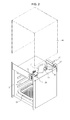
- a steam cooking apparatus which is designated by reference numeral 1, includes a main body 10 to define an external appearance thereof while having a cooking chamber 12 within the main body 10, a cover 14 to cover an upper portion, opposite side portions, and a rear portion of the main body 10, convection heaters 16 and convection fans 17 arranged at the upper portion and the rear portion of the main body 10 in order to heat the cooking chamber 12, and a steam generating unit 60 to generate steam so as to supply the generated steam to a steam container 13 in the cooking chamber 12.
- the main body 10 is opened at a front thereof to put food into or take food out of the cooking chamber 12, and the cooking chamber 12 on which food is placed is opened and closed by a door 18 coupled at the front of the main body 10.
- the main body 10 is arranged, at an upper portion of the front surface thereof, with a control panel 15 which has a variety of operation switches 15a to allow a user to control operations of the steam cooking apparatus 1.
- the control panel 15 is arranged, at a side thereof, with a water supply unit 20 to supply the steam generating unit 60 with water.
- the water supply unit 20 has a slider 24 capable of being withdrawn forward from the front surface of the main body 10. A user may supply water to or discharge water from the steam generating unit 60 by withdrawal of the slider 24.
- the convection heaters 16 arranged at the upper portion and the rear portion of the main body 10 provide heat to heat food within the cooking chamber 12.
- the convection fans 17 circulate heat generated by the convection heater 16 in the cooking chamber 12 through convection, or evenly circulate the steam generated by the steam generating unit 60 at the steam container in the cooking chamber 12, independently of the convection heaters 16.
- a first water supply tube 91 and a drainage pump 49 are located in a space between the upper portion of the main body 10 and the cover 14.
- the first water supply tube 91 connects the water supply unit 20 and a storage container 50, and the drainage pump 49 is connected with a drainage tube 94 to discharge water remaining within the steam generating unit 60 to the outside of the main body 10.
- the first water supply tube 91 is coupled, at one end thereof, to a connection portion 26 of the slider 24 in the water supply unit 20 while being coupled, at the other end thereof, to an inlet 52 of the storage container 50 described below, thereby guiding the water supplied to the slider 24 into the storage container 50.
- connection portion 26 of the slider 24 is arranged at a relatively higher position than the inlet 52 of the storage container 50, an additional pump is not needed.
- the water supplied to the slider 24 is introduced into the storage container 50 along the first water supply tube 91 by gravity.
- the first water supply tube 91 is frequently moved along with the slider 24 while the slider 24 is withdrawn in a forward direction of the main body 10 or inserted in an inward direction of the main body 10. Therefore, the first water supply tube 91 may be made of a material such as a synthetic resin or rubber, for example which is easily bent and does not undergo deformation in shape by repeated movement.
- the storage container 50, the steam generating unit 60, and an auxiliary steam generating unit 80 are located in a space between the rear portion of the main body 10 and the cover 14.
- the storage container 50 temporarily stores the water supplied from the water supply unit 20, the steam generating unit 60 is arranged beneath the storage container 50 to generate steam through heating of the water supplied from the storage container 50 and supply the steam into the cooking chamber 12, and the auxiliary steam generating unit 80 is connected with the steam generating unit 60 while being provided with a water level measuring sensor(not shown) to measure a level of the water stored within the steam generating unit 60.
- the storage container 50 is connected with the steam generating unit 60 through a second water supply tube 92, and the steam generating unit 60 is connected with the auxiliary steam generating unit 80 through a third water supply tube 93.
- the second water supply tube 92 serves to guide the water stored within the storage container 50 to the steam generating unit 60 when the steam is required to be supplied into the cooking chamber 12.
- the third water supply tube 93 allows the steam generating unit 60 and the auxiliary steam generating unit 80 to communicate with each other so that the level (a height from a bottom surface at which the steam cooking apparatus 1 is installed to a surface of the water stored within the steam generating unit 60) of the water stored within the steam generating unit 60 and the level (a height from the bottom surface at which the steam cooking apparatus 1 is installed to a surface of the water stored within the auxiliary steam generating unit 80) of the water stored within the auxiliary steam generating unit 80 are actually maintained equal to each other.
- the second water supply tube 92 is coupled, at a partial section thereof, with a valve 95 to control an amount of the water which is moved from the storage container 50 to the steam generating unit 60, if necessary.
- the steam generating unit 60 is connected, at a lower portion thereof, with the drainage tube 94 to discharge the water remaining within the steam generating unit 60 to the outside of the main body 10.
- the drainage tube 94 is fixed, at one end thereof, to the slider 24 to be withdrawn out of the main body 10 together with the slider 24 in the course of discharging the water remaining within the steam generating unit 60 to the outside of the main body 10.
- the steam pipe assembly includes a steam supply pipe 100 coupled to the steam generating unit 60, a steam pipe 200 coupled to the steam container 13, and a steam pipe connection tube 300 coupled, at opposite ends thereof, to the steam supply pipe 100 and the steam pipe 200 so as to connect the steam supply pipe 100 and the steam pipe 200.
- the steam generated by the steam generating unit 60 is supplied to the steam container 13 through the steam pipe assembly so that food within the steam container 13 is cooked by the steam supplied to the steam container 13.
- the steam supply pipe 100 is coupled to the steam generating unit 60 to serve as a passage to move the steam generated by the steam generating unit 60.
- the steam supply pipe 100 may be made of a pipe formed of a material that is easily bent, such as rubber, for example.
- the steam passing through the steam supply pipe 100 is moved through the steam pipe connection tube 300 coupled to the steam supply pipe 100 and the steam pipe 200 coupled to the steam pipe connection tube 300, and is then supplied to the steam container 13.
- the steam pipe 200 supplies the steam container 13 with the steam which passes through the steam supply pipe 100 coupled to the steam generating unit 60 and the steam pipe connection tube 300 coupled to the steam supply pipe 100.
- the steam pipe 200 is formed of a straight pipe having a circular shape.
- the steam pipe 200 includes a first coupling portion 210 coupled with the steam pipe connection tube 300 and a second coupling portion 230 coupled with the steam container 13.
- the first and second coupling portions 210 and 230 of the steam pipe 200 are formed with first and second protrusions 210A and 230A, respectively.
- Each of the first and second protrusions 210A and 230A has the same circular shape as the steam pipe 200 while being formed to protrude in a radial direction of the steam pipe 200.
- the first coupling portion 210 of the steam pipe 200 is inserted into and coupled to the steam pipe connection tube 300.
- the first protrusion 210A formed at the first coupling portion 210 is coupled to come into close contact with an expanded second connection portion 330 of the steam pipe connection tube 300 described below.
- the expanded second connection portion 330 of the steam pipe connection tube 300 is formed to have a high slope
- the first protrusion 210A may come into close contact with and be coupled to the second connection portion 330.
- the second connection portion 330 is formed to have a low slope, even when the first coupling portion 210 of the steam pipe 200 is slightly inserted into the steam pipe connection tube 300, the first protrusion 210A may come into close contact with and be coupled to the second connection portion 330.
- the first protrusion 210A formed at the first coupling portion 210 of the steam pipe 200 comes into close contact with and is coupled to the expanded second connection portion 330 of the steam pipe connection tube 300, it may be possible to prevent leakage of the steam supplied from the steam generating unit 60 to the steam container 13.
- the second coupling portion 230 of the steam pipe 200 is fitted with a fastening member B.
- the second coupling portion 230 of the steam pipe 200 is coupled with the steam container 13 by the fastening member B.
- the fastening member B fitted to the second coupling portion 230 of the steam pipe 200 is fixed so as not to be moved toward the first coupling portion 210 by the second protrusion 230A formed at the second coupling portion 230.
- the steam pipe connection tube 300 connects the steam supply pipe 100 and the steam pipe 200, thereby supplying the steam container 13 with the steam generated by the steam generating unit 60.
- the steam pipe connection tube 300 includes a first connection portion 310 coupled with the steam supply pipe 100 and a second connection portion 330 coupled with the steam pipe 200.
- the first connection portion 310 of the steam pipe connection tube 300 is inserted into and coupled to the steam supply pipe 100.
- the second connection portion 330 coupled with the steam pipe 200 is formed to have a diameter which is expanded toward the steam pipe 200.
- the expanded second connection portion 330 of the steam pipe connection tube 300 guides the steam pipe 200 to lead insertion of the steam pipe 200 when the steam pipe 200 is coupled to the steam pipe connection tube 300.
- the steam pipe 200 may be easily coupled to the steam pipe connection tube 300 by the expanded second connection portion 330 of the steam pipe connection tube 300 to which the steam pipe 200 is coupled.
- the first coupling portion 210 of the steam pipe 200 coupled to the second connection portion 330 of the steam pipe connection tube 300 is formed with the first protrusion 210A protruding in the radial direction of the steam pipe 200, the first protrusion 210A comes into close contact with and is coupled to the expanded second connection portion 330 when the steam pipe 200 is coupled to the steam pipe connection tube 300. As a result, it may be possible to prevent leakage of the steam supplied from the steam generating unit 60 to the steam container 13.
- the steam pipe connection tube 300 coupled with the steam pipe 200 is fixed to a cover casing 19.
- the steam pipe connection tube 300 is coupled with a coupling member 400 in order to fix the steam pipe connection tube 300 to the cover casing 19.
- the coupling member 400 is welded to the cover casing 19 so that the steam pipe connection tube 300 is fixed to the cover casing 19.
- the coupling member 400 includes a cover portion 410 coupled to the steam pipe connection tube 300 and an extended portion 430 formed to extend in a radial direction of the cover portion 410 from the cover portion 410.
- the cover portion 410 of the coupling member 400 is formed to have a shape which wraps an outer portion of the expanded second connection portion 330 of the steam pipe connection tube 300 to be coupled to the steam pipe connection tube 300.
- the extended portion 430 is welded to the cover casing 19 so as to allow the steam pipe connection tube 300 to be fixed to the cover casing 19.
- the cover casing 19 is formed with a connection hole 19A to connect the steam pipe connection tube 300 with the steam pipe 200.
- the extended portion 430 of the coupling member 400 is welded around the connection hole 19A of the cover casing 19.
- a center of the steam pipe connection tube 300 may exactly match a center of the connection hole 19A formed at the cover casing 19 when the steam pipe connection tube 300 is fixed to the cover casing 19, thereby enabling fixation of the steam pipe connection tube 300.
- the cover casing 19 and the steam pipe connection tube 300 is coated in order to prevent rust. Since the steam pipe connection tube 300 is directly fixed to the cover casing 19 by the coupling member 400, the cover casing 19 and the steam pipe connection tube 300 may be simultaneously coated.
- cover casing 19 and the steam pipe connection tube 300 are simultaneously coated, processing costs due to a coating may be reduced, and an improved aesthetically pleasing external appearance may also be achieved.
- the steam pipe may be properly seated and coupled to the steam pipe connection tube during coupling of the steam pipe and the steam pipe connection tube, thereby enabling leakage prevention of steam being supplied to the steam container.
- the steam pipe connection tube and the cover casing are assembled so that the centers thereof match each other, thereby enabling improvement in productivity and quality.
Landscapes
- Engineering & Computer Science (AREA)
- General Engineering & Computer Science (AREA)
- Mechanical Engineering (AREA)
- Food Science & Technology (AREA)
- Chemical & Material Sciences (AREA)
- Combustion & Propulsion (AREA)
- Life Sciences & Earth Sciences (AREA)
- Cookers (AREA)
Applications Claiming Priority (1)
| Application Number | Priority Date | Filing Date | Title |
|---|---|---|---|
| KR1020110040188A KR101860714B1 (ko) | 2011-04-28 | 2011-04-28 | 스팀조리기기 |
Publications (2)
| Publication Number | Publication Date |
|---|---|
| EP2517563A1 true EP2517563A1 (fr) | 2012-10-31 |
| EP2517563B1 EP2517563B1 (fr) | 2018-09-12 |
Family
ID=46045865
Family Applications (1)
| Application Number | Title | Priority Date | Filing Date |
|---|---|---|---|
| EP12165668.0A Active EP2517563B1 (fr) | 2011-04-28 | 2012-04-26 | Appareil de cuisson à vapeur |
Country Status (4)
| Country | Link |
|---|---|
| US (2) | US8997638B2 (fr) |
| EP (1) | EP2517563B1 (fr) |
| KR (1) | KR101860714B1 (fr) |
| CN (1) | CN102755103A (fr) |
Cited By (2)
| Publication number | Priority date | Publication date | Assignee | Title |
|---|---|---|---|---|
| EP3180984A1 (fr) * | 2015-12-18 | 2017-06-21 | BSH Hausgeräte GmbH | Appareil de cuisson |
| WO2022128311A1 (fr) * | 2020-12-16 | 2022-06-23 | BSH Hausgeräte GmbH | Système constitué d'un dispositif de cuisson et d'un récipient d'évaporation passive d'eau |
Families Citing this family (16)
| Publication number | Priority date | Publication date | Assignee | Title |
|---|---|---|---|---|
| US9872581B2 (en) * | 2012-05-16 | 2018-01-23 | Bsh Home Appliances Corporation | Home appliance with recessed water vessel housing |
| KR101931364B1 (ko) * | 2012-08-30 | 2018-12-21 | 삼성전자주식회사 | 스팀발생장치 및 이를 이용한 조리기기 |
| DE102015106705A1 (de) * | 2015-04-30 | 2016-11-03 | Miele & Cie. Kg | Gargerät, Verfahren zu dessen Betrieb sowie ein Gargutträger |
| EP3108774B1 (fr) * | 2015-06-24 | 2021-01-13 | Electrolux Appliances Aktiebolag | Recipient de cuisson pour la cavite d'un four de cuisson |
| CN105747885B (zh) * | 2016-05-19 | 2018-05-29 | 广东恒基卓越电器科技有限公司 | 自动供水式储水箱 |
| EP3339746B1 (fr) * | 2016-12-21 | 2020-05-20 | Electrolux Appliances Aktiebolag | Four domestique à vapeur |
| CN113647800B (zh) * | 2017-05-25 | 2022-07-15 | 三星电子株式会社 | 蒸汽烹调器 |
| AU2018316266A1 (en) | 2017-08-09 | 2020-02-20 | Sharkninja Operating Llc | Cooking device and components thereof |
| US20190309957A1 (en) * | 2018-04-09 | 2019-10-10 | Whirlpool Corporation | Steam generating system |
| KR102076662B1 (ko) | 2018-04-27 | 2020-02-12 | 엘지전자 주식회사 | 조리기기 |
| KR102060182B1 (ko) * | 2018-05-23 | 2019-12-27 | 엘지전자 주식회사 | 스팀발생장치 |
| US10813490B2 (en) * | 2019-01-31 | 2020-10-27 | Whirlpool Corporation | Water inlet connectivity for steam oven |
| EP3931493A1 (fr) | 2019-02-25 | 2022-01-05 | SharkNinja Operating LLC | Système de cuisson avec protection |
| US20190254476A1 (en) | 2019-02-25 | 2019-08-22 | Sharkninja Operating Llc | Cooking device and components thereof |
| KR20220084276A (ko) * | 2019-08-20 | 2022-06-21 | 요-카이 익스프레스 인크. | 식품 가열 장치 및 이를 사용한 식품 가열 방법 |
| US11647861B2 (en) | 2020-03-30 | 2023-05-16 | Sharkninja Operating Llc | Cooking device and components thereof |
Citations (3)
| Publication number | Priority date | Publication date | Assignee | Title |
|---|---|---|---|---|
| US4298206A (en) * | 1974-04-21 | 1981-11-03 | Noriatsu Kojima | Flexible packing for sealing pipeline joints |
| US5511831A (en) * | 1993-01-04 | 1996-04-30 | Modine Manufacturing Company | Self-centering, self-seating, double-sealing, interference fit tube joint |
| EP1783430A1 (fr) * | 2004-08-02 | 2007-05-09 | Sharp Kabushiki Kaisha | Cuiseur à vapeur |
Family Cites Families (16)
| Publication number | Priority date | Publication date | Assignee | Title |
|---|---|---|---|---|
| US3774008A (en) * | 1971-03-03 | 1973-11-20 | T Maniscalco | Steam generating apparatus |
| FR2564308B1 (fr) * | 1984-05-17 | 1987-08-21 | Jovanovic Dragomir | Appareil de cuisson a injection de vapeur a pression atmospherique |
| FR2600756B1 (fr) * | 1986-06-27 | 1990-05-11 | Jovanovic Dragomir | Appareil de cuisson a vapeur avec tournebroche |
| US5404803A (en) * | 1992-12-17 | 1995-04-11 | Appliance Development Corporation | Food steamer utensil |
| JP3751057B2 (ja) * | 1995-10-04 | 2006-03-01 | 松下電器産業株式会社 | マイクロ波加熱装置 |
| US6631740B1 (en) * | 2001-10-24 | 2003-10-14 | Eaton Corporation | Brazing joint for tubes and the like |
| KR100629336B1 (ko) | 2004-11-05 | 2006-09-29 | 엘지전자 주식회사 | 스팀 오븐의 증기 발생 장치 |
| US6947664B1 (en) * | 2004-11-24 | 2005-09-20 | Yin-Ting Yeh | Portable warm bag having steam heating device |
| KR20060082472A (ko) | 2005-01-12 | 2006-07-18 | 엘지전자 주식회사 | 증기수병 장착기능을 구비한 스팀 오븐 |
| US7326891B2 (en) * | 2005-06-08 | 2008-02-05 | Samsung Electronics Co., Ltd. | Steam generation apparatus using induction heating and oven including the same |
| JP4589825B2 (ja) * | 2005-06-23 | 2010-12-01 | 株式会社東芝 | 加熱調理装置 |
| EP1772080A3 (fr) * | 2005-09-26 | 2009-03-04 | Miele & Cie. KG | Procédé et dispositif pour cuire à la vapeur |
| CN100493425C (zh) * | 2006-04-14 | 2009-06-03 | 曹辉 | 蒸汽循环加热的烹调方法以及使用该方法的烹调器具 |
| US20090250452A1 (en) * | 2006-08-08 | 2009-10-08 | Sze-Man Tse | Steam Convection Oven |
| KR101185556B1 (ko) * | 2007-04-24 | 2012-09-25 | 삼성전자주식회사 | 파이프 연결소켓 및 이를 갖춘 공기조화기 |
| KR101005637B1 (ko) | 2008-09-11 | 2011-01-05 | 강원영 | 공조시스템의 배관 연결구조 및 공조시스템에 구비되는 배관 연결방법 |
-
2011
- 2011-04-28 KR KR1020110040188A patent/KR101860714B1/ko active IP Right Grant
-
2012
- 2012-04-23 US US13/453,182 patent/US8997638B2/en active Active
- 2012-04-26 EP EP12165668.0A patent/EP2517563B1/fr active Active
- 2012-04-28 CN CN2012101304274A patent/CN102755103A/zh active Pending
-
2015
- 2015-03-03 US US14/636,626 patent/US9801487B2/en active Active
Patent Citations (3)
| Publication number | Priority date | Publication date | Assignee | Title |
|---|---|---|---|---|
| US4298206A (en) * | 1974-04-21 | 1981-11-03 | Noriatsu Kojima | Flexible packing for sealing pipeline joints |
| US5511831A (en) * | 1993-01-04 | 1996-04-30 | Modine Manufacturing Company | Self-centering, self-seating, double-sealing, interference fit tube joint |
| EP1783430A1 (fr) * | 2004-08-02 | 2007-05-09 | Sharp Kabushiki Kaisha | Cuiseur à vapeur |
Cited By (2)
| Publication number | Priority date | Publication date | Assignee | Title |
|---|---|---|---|---|
| EP3180984A1 (fr) * | 2015-12-18 | 2017-06-21 | BSH Hausgeräte GmbH | Appareil de cuisson |
| WO2022128311A1 (fr) * | 2020-12-16 | 2022-06-23 | BSH Hausgeräte GmbH | Système constitué d'un dispositif de cuisson et d'un récipient d'évaporation passive d'eau |
Also Published As
| Publication number | Publication date |
|---|---|
| US20150173553A1 (en) | 2015-06-25 |
| KR101860714B1 (ko) | 2018-05-25 |
| KR20120122171A (ko) | 2012-11-07 |
| CN102755103A (zh) | 2012-10-31 |
| EP2517563B1 (fr) | 2018-09-12 |
| US20120272833A1 (en) | 2012-11-01 |
| US9801487B2 (en) | 2017-10-31 |
| US8997638B2 (en) | 2015-04-07 |
Similar Documents
| Publication | Publication Date | Title |
|---|---|---|
| EP2517563A1 (fr) | Appareil de cuisson à vapeur | |
| EP1905330B1 (fr) | Générateur de vapeur et appareil de cuisson chauffant doté de celui-ci | |
| EP1654931B1 (fr) | Générateur de vapeur pour un four à vapeur | |
| EP2775217B1 (fr) | Appareil de cuisson à vapeur | |
| KR102642751B1 (ko) | 조리기기 | |
| JP4049787B2 (ja) | 過熱蒸気調理器 | |
| US7323662B2 (en) | Heating apparatus for cooking | |
| EP1543754B1 (fr) | Appareil de cuisson | |
| US20070068918A1 (en) | Method and device for cooking with steam | |
| US20050051531A1 (en) | Overheated steam oven | |
| US9488377B2 (en) | Gas oven range | |
| US6930286B2 (en) | Heating cooker | |
| KR20060082472A (ko) | 증기수병 장착기능을 구비한 스팀 오븐 | |
| EP1767861B1 (fr) | Dispositif de cuisson hyperfréquence | |
| US20220057087A1 (en) | Electronic cooking apparatus having steam supply device | |
| CN109477639A (zh) | 加热调理器 | |
| JP2007147275A (ja) | 高周波調理器 | |
| US10465914B2 (en) | Cooking device | |
| JP2006017404A (ja) | 高周波調理器 | |
| KR200366593Y1 (ko) | 커피메이커용 서모스탯 장착구조 | |
| KR100471077B1 (ko) | 제빵기 |
Legal Events
| Date | Code | Title | Description |
|---|---|---|---|
| PUAI | Public reference made under article 153(3) epc to a published international application that has entered the european phase |
Free format text: ORIGINAL CODE: 0009012 |
|
| AK | Designated contracting states |
Kind code of ref document: A1 Designated state(s): AL AT BE BG CH CY CZ DE DK EE ES FI FR GB GR HR HU IE IS IT LI LT LU LV MC MK MT NL NO PL PT RO RS SE SI SK SM TR |
|
| AX | Request for extension of the european patent |
Extension state: BA ME |
|
| 17P | Request for examination filed |
Effective date: 20130430 |
|
| 17Q | First examination report despatched |
Effective date: 20150225 |
|
| STAA | Information on the status of an ep patent application or granted ep patent |
Free format text: STATUS: EXAMINATION IS IN PROGRESS |
|
| GRAP | Despatch of communication of intention to grant a patent |
Free format text: ORIGINAL CODE: EPIDOSNIGR1 |
|
| STAA | Information on the status of an ep patent application or granted ep patent |
Free format text: STATUS: GRANT OF PATENT IS INTENDED |
|
| RIC1 | Information provided on ipc code assigned before grant |
Ipc: A47J 27/04 20060101ALI20180320BHEP Ipc: F16L 25/10 20060101ALI20180320BHEP Ipc: F24C 15/00 20060101ALI20180320BHEP Ipc: A61M 39/10 20060101ALI20180320BHEP Ipc: F24C 15/32 20060101ALI20180320BHEP Ipc: A21B 3/04 20060101AFI20180320BHEP |
|
| INTG | Intention to grant announced |
Effective date: 20180406 |
|
| GRAS | Grant fee paid |
Free format text: ORIGINAL CODE: EPIDOSNIGR3 |
|
| GRAA | (expected) grant |
Free format text: ORIGINAL CODE: 0009210 |
|
| STAA | Information on the status of an ep patent application or granted ep patent |
Free format text: STATUS: THE PATENT HAS BEEN GRANTED |
|
| AK | Designated contracting states |
Kind code of ref document: B1 Designated state(s): AL AT BE BG CH CY CZ DE DK EE ES FI FR GB GR HR HU IE IS IT LI LT LU LV MC MK MT NL NO PL PT RO RS SE SI SK SM TR |
|
| REG | Reference to a national code |
Ref country code: GB Ref legal event code: FG4D |
|
| REG | Reference to a national code |
Ref country code: CH Ref legal event code: EP |
|
| REG | Reference to a national code |
Ref country code: IE Ref legal event code: FG4D |
|
| REG | Reference to a national code |
Ref country code: DE Ref legal event code: R096 Ref document number: 602012050890 Country of ref document: DE |
|
| REG | Reference to a national code |
Ref country code: AT Ref legal event code: REF Ref document number: 1039516 Country of ref document: AT Kind code of ref document: T Effective date: 20181015 |
|
| REG | Reference to a national code |
Ref country code: NL Ref legal event code: MP Effective date: 20180912 |
|
| REG | Reference to a national code |
Ref country code: LT Ref legal event code: MG4D |
|
| PG25 | Lapsed in a contracting state [announced via postgrant information from national office to epo] |
Ref country code: FI Free format text: LAPSE BECAUSE OF FAILURE TO SUBMIT A TRANSLATION OF THE DESCRIPTION OR TO PAY THE FEE WITHIN THE PRESCRIBED TIME-LIMIT Effective date: 20180912 Ref country code: LT Free format text: LAPSE BECAUSE OF FAILURE TO SUBMIT A TRANSLATION OF THE DESCRIPTION OR TO PAY THE FEE WITHIN THE PRESCRIBED TIME-LIMIT Effective date: 20180912 Ref country code: RS Free format text: LAPSE BECAUSE OF FAILURE TO SUBMIT A TRANSLATION OF THE DESCRIPTION OR TO PAY THE FEE WITHIN THE PRESCRIBED TIME-LIMIT Effective date: 20180912 Ref country code: SE Free format text: LAPSE BECAUSE OF FAILURE TO SUBMIT A TRANSLATION OF THE DESCRIPTION OR TO PAY THE FEE WITHIN THE PRESCRIBED TIME-LIMIT Effective date: 20180912 Ref country code: NO Free format text: LAPSE BECAUSE OF FAILURE TO SUBMIT A TRANSLATION OF THE DESCRIPTION OR TO PAY THE FEE WITHIN THE PRESCRIBED TIME-LIMIT Effective date: 20181212 Ref country code: GR Free format text: LAPSE BECAUSE OF FAILURE TO SUBMIT A TRANSLATION OF THE DESCRIPTION OR TO PAY THE FEE WITHIN THE PRESCRIBED TIME-LIMIT Effective date: 20181213 Ref country code: BG Free format text: LAPSE BECAUSE OF FAILURE TO SUBMIT A TRANSLATION OF THE DESCRIPTION OR TO PAY THE FEE WITHIN THE PRESCRIBED TIME-LIMIT Effective date: 20181212 |
|
| PG25 | Lapsed in a contracting state [announced via postgrant information from national office to epo] |
Ref country code: LV Free format text: LAPSE BECAUSE OF FAILURE TO SUBMIT A TRANSLATION OF THE DESCRIPTION OR TO PAY THE FEE WITHIN THE PRESCRIBED TIME-LIMIT Effective date: 20180912 Ref country code: HR Free format text: LAPSE BECAUSE OF FAILURE TO SUBMIT A TRANSLATION OF THE DESCRIPTION OR TO PAY THE FEE WITHIN THE PRESCRIBED TIME-LIMIT Effective date: 20180912 Ref country code: AL Free format text: LAPSE BECAUSE OF FAILURE TO SUBMIT A TRANSLATION OF THE DESCRIPTION OR TO PAY THE FEE WITHIN THE PRESCRIBED TIME-LIMIT Effective date: 20180912 |
|
| REG | Reference to a national code |
Ref country code: AT Ref legal event code: MK05 Ref document number: 1039516 Country of ref document: AT Kind code of ref document: T Effective date: 20180912 |
|
| PG25 | Lapsed in a contracting state [announced via postgrant information from national office to epo] |
Ref country code: IT Free format text: LAPSE BECAUSE OF FAILURE TO SUBMIT A TRANSLATION OF THE DESCRIPTION OR TO PAY THE FEE WITHIN THE PRESCRIBED TIME-LIMIT Effective date: 20180912 Ref country code: ES Free format text: LAPSE BECAUSE OF FAILURE TO SUBMIT A TRANSLATION OF THE DESCRIPTION OR TO PAY THE FEE WITHIN THE PRESCRIBED TIME-LIMIT Effective date: 20180912 Ref country code: NL Free format text: LAPSE BECAUSE OF FAILURE TO SUBMIT A TRANSLATION OF THE DESCRIPTION OR TO PAY THE FEE WITHIN THE PRESCRIBED TIME-LIMIT Effective date: 20180912 Ref country code: CZ Free format text: LAPSE BECAUSE OF FAILURE TO SUBMIT A TRANSLATION OF THE DESCRIPTION OR TO PAY THE FEE WITHIN THE PRESCRIBED TIME-LIMIT Effective date: 20180912 Ref country code: RO Free format text: LAPSE BECAUSE OF FAILURE TO SUBMIT A TRANSLATION OF THE DESCRIPTION OR TO PAY THE FEE WITHIN THE PRESCRIBED TIME-LIMIT Effective date: 20180912 Ref country code: EE Free format text: LAPSE BECAUSE OF FAILURE TO SUBMIT A TRANSLATION OF THE DESCRIPTION OR TO PAY THE FEE WITHIN THE PRESCRIBED TIME-LIMIT Effective date: 20180912 Ref country code: AT Free format text: LAPSE BECAUSE OF FAILURE TO SUBMIT A TRANSLATION OF THE DESCRIPTION OR TO PAY THE FEE WITHIN THE PRESCRIBED TIME-LIMIT Effective date: 20180912 Ref country code: PL Free format text: LAPSE BECAUSE OF FAILURE TO SUBMIT A TRANSLATION OF THE DESCRIPTION OR TO PAY THE FEE WITHIN THE PRESCRIBED TIME-LIMIT Effective date: 20180912 Ref country code: IS Free format text: LAPSE BECAUSE OF FAILURE TO SUBMIT A TRANSLATION OF THE DESCRIPTION OR TO PAY THE FEE WITHIN THE PRESCRIBED TIME-LIMIT Effective date: 20190112 |
|
| PG25 | Lapsed in a contracting state [announced via postgrant information from national office to epo] |
Ref country code: SK Free format text: LAPSE BECAUSE OF FAILURE TO SUBMIT A TRANSLATION OF THE DESCRIPTION OR TO PAY THE FEE WITHIN THE PRESCRIBED TIME-LIMIT Effective date: 20180912 Ref country code: SM Free format text: LAPSE BECAUSE OF FAILURE TO SUBMIT A TRANSLATION OF THE DESCRIPTION OR TO PAY THE FEE WITHIN THE PRESCRIBED TIME-LIMIT Effective date: 20180912 Ref country code: PT Free format text: LAPSE BECAUSE OF FAILURE TO SUBMIT A TRANSLATION OF THE DESCRIPTION OR TO PAY THE FEE WITHIN THE PRESCRIBED TIME-LIMIT Effective date: 20190112 |
|
| REG | Reference to a national code |
Ref country code: DE Ref legal event code: R097 Ref document number: 602012050890 Country of ref document: DE |
|
| PLBE | No opposition filed within time limit |
Free format text: ORIGINAL CODE: 0009261 |
|
| STAA | Information on the status of an ep patent application or granted ep patent |
Free format text: STATUS: NO OPPOSITION FILED WITHIN TIME LIMIT |
|
| PG25 | Lapsed in a contracting state [announced via postgrant information from national office to epo] |
Ref country code: DK Free format text: LAPSE BECAUSE OF FAILURE TO SUBMIT A TRANSLATION OF THE DESCRIPTION OR TO PAY THE FEE WITHIN THE PRESCRIBED TIME-LIMIT Effective date: 20180912 |
|
| 26N | No opposition filed |
Effective date: 20190613 |
|
| PG25 | Lapsed in a contracting state [announced via postgrant information from national office to epo] |
Ref country code: SI Free format text: LAPSE BECAUSE OF FAILURE TO SUBMIT A TRANSLATION OF THE DESCRIPTION OR TO PAY THE FEE WITHIN THE PRESCRIBED TIME-LIMIT Effective date: 20180912 |
|
| REG | Reference to a national code |
Ref country code: CH Ref legal event code: PL |
|
| REG | Reference to a national code |
Ref country code: BE Ref legal event code: MM Effective date: 20190430 |
|
| PG25 | Lapsed in a contracting state [announced via postgrant information from national office to epo] |
Ref country code: LU Free format text: LAPSE BECAUSE OF NON-PAYMENT OF DUE FEES Effective date: 20190426 Ref country code: MC Free format text: LAPSE BECAUSE OF FAILURE TO SUBMIT A TRANSLATION OF THE DESCRIPTION OR TO PAY THE FEE WITHIN THE PRESCRIBED TIME-LIMIT Effective date: 20180912 |
|
| PG25 | Lapsed in a contracting state [announced via postgrant information from national office to epo] |
Ref country code: LI Free format text: LAPSE BECAUSE OF NON-PAYMENT OF DUE FEES Effective date: 20190430 Ref country code: CH Free format text: LAPSE BECAUSE OF NON-PAYMENT OF DUE FEES Effective date: 20190430 |
|
| PG25 | Lapsed in a contracting state [announced via postgrant information from national office to epo] |
Ref country code: BE Free format text: LAPSE BECAUSE OF NON-PAYMENT OF DUE FEES Effective date: 20190430 Ref country code: FR Free format text: LAPSE BECAUSE OF NON-PAYMENT OF DUE FEES Effective date: 20190430 |
|
| PG25 | Lapsed in a contracting state [announced via postgrant information from national office to epo] |
Ref country code: TR Free format text: LAPSE BECAUSE OF FAILURE TO SUBMIT A TRANSLATION OF THE DESCRIPTION OR TO PAY THE FEE WITHIN THE PRESCRIBED TIME-LIMIT Effective date: 20180912 |
|
| PG25 | Lapsed in a contracting state [announced via postgrant information from national office to epo] |
Ref country code: IE Free format text: LAPSE BECAUSE OF NON-PAYMENT OF DUE FEES Effective date: 20190426 |
|
| PG25 | Lapsed in a contracting state [announced via postgrant information from national office to epo] |
Ref country code: CY Free format text: LAPSE BECAUSE OF FAILURE TO SUBMIT A TRANSLATION OF THE DESCRIPTION OR TO PAY THE FEE WITHIN THE PRESCRIBED TIME-LIMIT Effective date: 20180912 |
|
| PG25 | Lapsed in a contracting state [announced via postgrant information from national office to epo] |
Ref country code: MT Free format text: LAPSE BECAUSE OF FAILURE TO SUBMIT A TRANSLATION OF THE DESCRIPTION OR TO PAY THE FEE WITHIN THE PRESCRIBED TIME-LIMIT Effective date: 20180912 Ref country code: HU Free format text: LAPSE BECAUSE OF FAILURE TO SUBMIT A TRANSLATION OF THE DESCRIPTION OR TO PAY THE FEE WITHIN THE PRESCRIBED TIME-LIMIT; INVALID AB INITIO Effective date: 20120426 |
|
| PGFP | Annual fee paid to national office [announced via postgrant information from national office to epo] |
Ref country code: GB Payment date: 20220321 Year of fee payment: 11 |
|
| PG25 | Lapsed in a contracting state [announced via postgrant information from national office to epo] |
Ref country code: MK Free format text: LAPSE BECAUSE OF FAILURE TO SUBMIT A TRANSLATION OF THE DESCRIPTION OR TO PAY THE FEE WITHIN THE PRESCRIBED TIME-LIMIT Effective date: 20180912 |
|
| PGFP | Annual fee paid to national office [announced via postgrant information from national office to epo] |
Ref country code: DE Payment date: 20230320 Year of fee payment: 12 |
|
| GBPC | Gb: european patent ceased through non-payment of renewal fee |
Effective date: 20230426 |
|
| PG25 | Lapsed in a contracting state [announced via postgrant information from national office to epo] |
Ref country code: GB Free format text: LAPSE BECAUSE OF NON-PAYMENT OF DUE FEES Effective date: 20230426 |
|
| PG25 | Lapsed in a contracting state [announced via postgrant information from national office to epo] |
Ref country code: GB Free format text: LAPSE BECAUSE OF NON-PAYMENT OF DUE FEES Effective date: 20230426 |