EP2515200A1 - Arithmetic processing device, information processing device, and method for controlling same - Google Patents
Arithmetic processing device, information processing device, and method for controlling same Download PDFInfo
- Publication number
- EP2515200A1 EP2515200A1 EP09852255A EP09852255A EP2515200A1 EP 2515200 A1 EP2515200 A1 EP 2515200A1 EP 09852255 A EP09852255 A EP 09852255A EP 09852255 A EP09852255 A EP 09852255A EP 2515200 A1 EP2515200 A1 EP 2515200A1
- Authority
- EP
- European Patent Office
- Prior art keywords
- instructions
- consumption current
- instruction
- arithmetic
- value
- Prior art date
- Legal status (The legal status is an assumption and is not a legal conclusion. Google has not performed a legal analysis and makes no representation as to the accuracy of the status listed.)
- Withdrawn
Links
Images

Classifications
-
- G—PHYSICS
- G06—COMPUTING; CALCULATING OR COUNTING
- G06F—ELECTRIC DIGITAL DATA PROCESSING
- G06F1/00—Details not covered by groups G06F3/00 - G06F13/00 and G06F21/00
- G06F1/26—Power supply means, e.g. regulation thereof
- G06F1/32—Means for saving power
- G06F1/3203—Power management, i.e. event-based initiation of a power-saving mode
- G06F1/3206—Monitoring of events, devices or parameters that trigger a change in power modality
-
- G—PHYSICS
- G06—COMPUTING; CALCULATING OR COUNTING
- G06F—ELECTRIC DIGITAL DATA PROCESSING
- G06F1/00—Details not covered by groups G06F3/00 - G06F13/00 and G06F21/00
- G06F1/26—Power supply means, e.g. regulation thereof
- G06F1/32—Means for saving power
- G06F1/3203—Power management, i.e. event-based initiation of a power-saving mode
- G06F1/3234—Power saving characterised by the action undertaken
Definitions
- the present invention is related to a processor, an information processing apparatus and a control method thereof.
- a consumption current is estimated for each clock cycle using a value having correlation with a current consumption defined for each instruction. Then, when a change rate thereof is larger than a predetermined value, instructions are transposed in such a manner that a change amount may become smaller, or an instruction is replaced by a dummy instruction.
- An object is to provide a processor that can positively reduce a change in a consumption current using a simple configuration.
- Instructions decoded by an instruction decoding part are issued to an arithmetic and logic part, a consumption current value the arithmetic and logic part has consumed by instructions issued during a first predetermined period and a consumption current expected value that the arithmetic and logic part consumes by instructions issuable during a second predetermined period are calculated, and in a case where a change amount of the consumption current expected value with respect to the consumption current value exceeds a predetermined limit value, issuance of some instructions is inhibited in the second predetermined period.
- a processor that is a semiconductor intergraded circuit
- power-supply noise is reduced by controlling the number of instructions to be issued or an issuance frequency thereof.
- a CPU Central Processing Unit
- a GPU Graphics Processing Unit
- DSP Digital Signal Processor
- a technology of reducing consumed power in a processor is an important technology for reducing consumed power of an information communication apparatus.
- a method of reducing an operation rate of a circuit is effective, such as clock gating of providing clock pulses only to registers that are required to carry out a process, enabling only RAM (Random Access Memories) that are required to carry out a process, or the like.
- a reduction in dI/dt that is a time rate of change of current is desired in order to avoid generation of power-supply noise caused by a difference in a consumption current occurring between a time of carrying out a process and a time of not carrying out a process.
- a method for controlling a circuit for reducing power-supply noise there is a method of reducing a time rate of change of current dI/dt into a low level by reducing a clock frequency into a low level at a time of starting operation of a circuit. Furthermore, there is a method of estimating consumption currents of instructions at a stage of compiling software, and adjusting issuance of instructions by the software.
- a data dependent hazard means a situation in which since plural instructions are executed in a manner of being jumbled together, the order of writing and/or reading of operation results becomes different from having been intended by a machine-language programmer, and a result different from an expected one occurs. Detecting a hazard and stopping the pipeline is referred to as pipeline interlock.
- pipeline interlock a consumption current is reduced since execution of instructions is stopped.
- a dummy circuit that only executes a dummy instruction is used.
- a “dummy instruction” means an instruction that does not influence subsequently executed instructions.
- a "dummy circuit” is a circuit that consumes a current by executing a dummy instruction and mitigates a reduction in a consumption current. Especially in a large-scale system, a scale of a dummy circuit for dealing with a reduction in a consumption current caused by pipeline interlock becomes larger, and it is considered that a chip area increases, consumed power increases, or so.
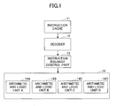
- FIG. 1 is a block diagram depicting an internal configuration of a processor as a reference example.
- a processor of FIG. 1 is, for example, a SPARC (Scalable Processor Architecture) processor, and includes an instruction cache (instruction storing part) 11, a decoder (instruction decoding part) 12, an instruction issuance control part 13 and an arithmetic and logic mechanism 14.
- the arithmetic and logic mechanism 14 includes arithmetic and logic units (arithmetic and logic parts) 14A, 14B, 14C and 14D.
- the instruction cache 11 is a cache memory that stores a program.
- the decoder 12 decodes instructions included in the program.
- the instruction issuance control part 13 issues the instructions to the arithmetic and logic units 14A, 14B, 14C and 14D.
- the arithmetic and logic units (ALU) 14A, 14B, 14C and 14D execute the issued instructions. Further, the arithmetic and logic units 14A, 14B, 14C and 14D share calculation functions, respectively.
- the arithmetic and logic unit 14A may carry out fixed-point adding and subtracting operations; the arithmetic and logic unit 14B may carry out fixed-point multiplying operations; the arithmetic and logic unit 14C may carry out floating-point adding and subtracting operations; and the arithmetic and logic unit 14D may carry out floating-point multiplying operations. It is noted that it is not necessary to limit to this example, and, for example, two or more of plural arithmetic and logic units may carry out the same arithmetic or logic function. Below, particularly, operations concerning issuance of instructions of a program will be described, out of the operations in the processor.
- the decoder 12 fetches (obtains) instructions from the instruction cache 11, decodes them and transfers them to the instruction issuance control part 13.
- the instruction issuance control part 13 issues instructions transferred from the decoder to the arithmetic and logic units 14A through 14D. More specifically, the instruction issuance control part 13 stores in an internal register (not depicted) instructions transferred from the decoder 12, and determines entries in the internal register which store issuable instructions. The instruction issuance control part 13 selects instructions to be issued from those stored in the determined entries. Selection of instructions to be actually issued is carried out for each arithmetic and logic unit that can execute a stored instruction.
- a priority order is given among instructions that the same arithmetic and logic unit can execute, and instructions to be issued are selected according to the priority order.
- the instruction issuance control part 13 issues selected instructions to the corresponding arithmetic and logic unit, and releases the corresponding entry after issuance of an instruction.
- the embodiment has a configuration of preventing generation of power-supply noise.
- estimated values of currents that have been consumed by instructions that have been issued during past several cycles are stored. It is noted that the above-mentioned estimated values are estimated values of currents consumed by the entirety of the processor. Then, an increasing amount of a consumption current value that is approximately calculated from issuable instructions at a present cycle with respect to the stored current values is calculated. Then, it is determined whether the calculated increasing amount exceeds an allowable current change amount (referred to as a limit value) of the processor. In a case where it exceeds the limit value, issuance of instructions is restricted so that the limit value will not be exceeded.
- the limit value may be obtained from a result of noise analysis simulation or from examining measured values.
- estimated values of currents consumed by instructions issued during past several cycles are stored and, with respect to these current values, a decreasing amount of a consumption current value that is approximately calculated from issuable instructions at a present cycle is calculated. Then, it is determined whether the calculated decreasing amount exceeds a limit value of the processor. In a case where it exceeds the limit value, a dummy instruction(s) is issued so that the limit value will not be exceeded.
- an existing instruction that does not influence execution of a program may be used, such as an instruction of, in a case of the SPARC architecture, using a Global register zero (gO) as a destination to which an operation result will be stored, for example.
- a new dummy instruction may be defined and used, such as an instruction that merely operates an existing circuit but does not change the state of a processor.
- a dummy instruction is desired to be an instruction that changes a consumption current as much as possible, as long as it does not exceed a limit value.
- Global register zero (gO) means a global register from which "0" is always obtained when it is read, and which has a value that is not changed even when writing is carried out thereto.
- an instruction issuance control unit in an instruction issuance control unit according to the embodiment, instructions that have been issued during past several cycles or estimated values of currents that have been consumed by the instructions are stored. Then, with respect to these current values, an increasing amount of a consumption current value that is approximately calculated from issuable instructions at a present cycle is calculated. Then, it is determined whether the calculated increasing amount exceeds a limit value of the processor. In a case where it exceeds the limit value, issuance of instructions is restricted so that the limit value will not be exceeded.
- an instruction issuance control unit in an instruction issuance control unit according to the embodiment, instructions that have been issued during past several cycles or estimated values of currents that have been consumed by the instructions are stored. Then, with respect to these current values, a decreasing amount of a consumption current value that is approximately calculated from issuable instructions at a present cycle is calculated. Then, it is determined whether the calculated decreasing amount exceeds a limit value of the processor. In a case where it exceeds the limit value, a dummy instruction(s) that does not influence subsequent executing instructions is issued so that the limit value will not be exceeded.
- issuance of instructions at a present cycle is restricted so that a condition of P(t) ⁇ P(t-1, t-N) + ⁇ P1 may be met.
- the variable t denotes a present cycle
- P(t-1, t-N) denotes an average consumption current that is estimated from instructions of past N cycles
- ⁇ P1 denotes a limit value allowable in the processor
- P(t) denotes a consumption current value that is estimated from instructions issuable at the present cycle.
- a dummy instruction(s) that does not influence subsequent executing instructions is issued at a present cycle so that a condition of P (t) ⁇ P (t-1, t-N) - ⁇ P2 may be met.
- t denotes a present cycle
- P(t-1, t-N) denotes an average consumption current that is estimated from instructions of past N cycles
- ⁇ P2 denotes a limit value allowable in the processor
- P(t) denotes a consumption current value that is estimated from instructions issuable at the present cycle.
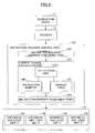
- FIG. 2 is a block diagram depicting an internal configuration of a processor according to the embodiment.
- a processor of FIG. 2 is, for example, a SPARC processor, and includes an instruction cache 11, a decoder 12, an instruction issuance control part 13X and an arithmetic and logic mechanism 14.
- the arithmetic and logic mechanism 14 includes arithmetic and logic units 14A, 14B, 14C and 14D.
- the instruction cache 11 is a cache memory that stores a program.
- the decoder 12 decodes instructions included in the program.
- the instruction issuance control part 13X issues the instructions to the arithmetic and logic units 14A, 14B, 14C and 14D.
- the arithmetic and logic units (ALU) 14A, 14B, 14C and 14D execute the issued instructions. Further, it is noted that the arithmetic and logic units 14A, 14B, 14C and 14D share calculation functions, respectively, as mentioned above.
- an instruction issuance mechanism (i.e., the instruction issuance control part 13X in the processor) has a current change calculation part 13C and an instruction issuance adjustment part 13A, in addition to an instruction issuance control functional part 13R that has a function of an instruction issuance control part of a prior art case.
- the current change calculation part 13C calculates a current change based on types and the number of instructions that are issued, and provides an instruction to restrict instruction issuance when the calculated current change exceeds a previously set threshold.
- the instruction issuance adjustment part 13A receives the instruction and limits instructions to be issued. As a result, it is possible to reduce power-supply noise caused by a time rate of change of current dI/dt.
- the decoder 12 fetches instructions from the instruction cache 11, decodes them and transfers them to the instruction issuance control part 13X.
- the instruction issuance control functional part 13R selects issuable instructions using a result of the decoding, and the current change calculation part 13C carries out the following issuance control for the selected instructions based on the consumption current change.
- the current change calculation part 13C of the instruction issuance control part 13X determines entries in an internal register which store issuable instructions. Then, based on types, the number and/or the like of the issuable instructions stored in the determined entries, an consumption current value when the arithmetic and logic units 14A, 14B, 14C and 14D execute the issuable instructions is calculated. The current change calculation part 13C further calculates an average consumption current for past several cycles using the number and types of instructions.
- the maximum number of instructions issuable during a predetermined period of time is determined to be within such a range that a change amount of a consumption current value (also simply referred to as a change amount) with respect to the past average consumption current when the issuable instructions are executed will not exceed a specific threshold (i.e., a limit value ⁇ I), and is transferred to the instruction issuance adjustment part 13A.
- a specific threshold i.e., a limit value ⁇ I
- the upper limit of the number of simultaneously issuable instructions is defined concerning hardware, and it is assumed that the number of simultaneously issuable instructions is to be equal to or less than the above-mentioned upper limit.
- the number of the arithmetic and logic units 14A, 14B, 14C and 14D is 4, and thus, the upper limit of simultaneously issuable instructions is 4.
- the instruction issuance adjustment part 13A receives the maximum number of instructions issuable during the predetermined period of time, and selects instructions to be actually issued based on respective arithmetic and logic units of the arithmetic and logic units 14A, 14B, 14C and 14D corresponding to respective instructions to be issued. Further, in a case where there are plural instructions issuable simultaneously, a priority order is provided among the plural instructions, and instructions are selected according to the priority order so that the number of instructions to be issued per 1 cycle may be within the maximum number of issuable instructions.
- instructions may be issued from among those currently issuable, from those having the earlier execution order in the program (from those having the smaller addresses in a case where the program is stored in the main memory when no branch instructions are included), i.e., based on the order of occurrences of instructions in the program, for example.
- the number of instructions may be limited by limiting the frequency of instruction issuances in such a manner of issuing instructions only at 1 cycle out of plural cycles, while the number of instructions issued per 1 cycle is maintained as it is.
- the instruction issuance control part 13X issues instructions to the corresponding ones of the arithmetic and logic units 14A, 14B, 14C and 14D in such a manner that the number of issuing instructions is limited as appropriate. After that, the instruction issuance control part 13X releases the entries of the issued instructions. Thus, instructions are issued as many as possible in such a range that the limit value is not exceeded.
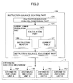
- the current change calculation part 13C is provided between the decoder 12 and the arithmetic and logic units 14A, 14B, 14C and 14D, and as depicted in FIG. 3 , has a calculation part 13CC, an instruction monitor 13M and a current table 13T.
- the instruction monitor 13M monitors the types and the number of issued of instructions that have been issued at a predetermined number of cycles up to the present time.
- the current table 13T stores, for each type of an instruction, a corresponding current estimated value (see FIG. 6 described later). It is noted that the current table 13T may store a current estimated value for each type of an instruction as mentioned above, or may store a current value per one instruction without regard to the types of instructions.
- the types and the current estimated values of instructions to be stored may have a configuration may be provided such that current estimated values may be changed by a program so that these may be adjusted at a time of operation of the LSI that includes the processor. Further, the above-mentioned current estimated values depending on the types of instructions may be previously obtained from power simulation that is carried out at a time of design of the LSI, for example, or, may be set as a result of consumed power for each instruction being obtained as a result of consumed power of the entire processor in an actually manufactured chip being measured.
- the calculation part 13CC of the current change calculation part 13C uses an instruction history for predetermined number of cycles stored by the instruction monitor 13M and currently issuable instructions, reads the current table 13T, and estimates a change amount of a consumption current. In a case where a consumption current increases and a current increasing amount as a change amount of a consumption current exceeds a limit value, the instruction issuance adjustment part 13A obtains the maximum number of issuable instructions so that the increasing amount may be equal to or less than the limit value, and outputs the maximum number of issuable instructions and the current calculation result.
- a consumption current in the arithmetic and logic units 14A, 14B, 14C and 14D is reduced, and the increasing amount is caused to be equal to or less than the limit value.
- the instruction issuance adjustment part 13A obtains the required number of dummy instructions to be issued so that the decreasing amount may be equal to or less than the limit value, and outputs the required number of dummy instructions to be issued and the current calculation result.
- a consumption current in the arithmetic and logic units 14A, 14B, 14C and 14D is increased, and the decreasing amount is caused to be equal to or less than the limit value.
- the instruction issuance adjustment part 13A limits instructions to be issued from the instruction issuance control part 13X during a predetermined period of time or issues the required number of dummy instructions, according to the maximum number of issuable instructions or the required number of dummy instructions, that is output from the current change calculation part 13C.
- the embodiment by providing the current change calculation part 13C and the instruction issuance adjustment part 13A in the instruction issuance control part 13X of the processor, it is possible to carry out current change control with higher precision depending on instructions that are actually executed.
- a monitoring method 1 there are a monitoring method 1 and a monitoring method 2, and any one of these may be used.
- the monitoring method 1 based on the number of instructions or an instruction issuance frequency at immediately preceding X cycles, the number of instructions to be issued or an instruction issuance frequency at the present cycle is controlled. Below, a specific example will be described.
- the maximum allowable current change value (i.e., a limit value) ⁇ I is previously set in the current change calculation part 13C.
- the calculation part 13CC of the current change calculation part 13C reads the instruction monitor 13M and the current table 13T, and calculates the average of the current estimated values of the instructions that have been issued at the immediately preceding X cycles (a calculation result will be referred to as A). Further, the current estimated value of the currently issuable instructions is also calculated (a calculation result will be referred to as B). Next, the difference in the current values B - A is calculated, and, when B - A > ⁇ I, the maximum number of issuable instructions is given to the instruction issuance adjustment part 13A from the current change calculation part 13C.
- the required number of dummy instructions is indicated to the instruction issuance adjustment part 13A from the current change calculation part 13C.
- Calculation of the consumption current change may be carried out every 1 cycle or may be carried out every certain period of cycles.
- a method of carrying out every certain period of cycles is a method of, not carrying out calculation of a consumption current change every cycle, but carrying out calculation of a current change every predetermined number of cycles.
- the monitoring method 2 based on the number of instructions or an instruction issuance frequency at the present and immediately preceding X cycles, including the present cycle, and also the number of instructions or an instruction issuance frequency at further preceding X cycles, the number of instructions to be issued or an instruction issuance frequency at the present cycle is controlled.
- the number of instructions to be issued or an instruction issuance frequency at the present cycle is controlled.
- the maximum allowable current change value (i.e., a limit value) ⁇ I is previously set in the current change calculation part 13C.
- the calculation part 13CC of the current change calculation part 13C reads the instruction monitor 13M and the current table 13T, and calculates the average or the sum of the current estimated values of the instructions that have been issued at the present and immediately preceding X cycles (a calculation result will be referred to as A) including the present cycle and the average or the sum of the current estimated values of the instructions that have been issued at the further preceding X cycles (a calculation result will be referred to as B), respectively, and compares them mutually.
- a noise having a high frequency has a short period and a noise having a low frequency has a long period. Therefore, by appropriately adjusting the above-mentioned value X depending on the frequency band of power-supply noise to be dealt with, it is possible to monitor the power-supply noise. Also in this case, calculation of a consumption current change may be carried out every 1 cycle or may be carried out every certain period of cycles. A method of carrying out every certain period of cycles is a method of, not carrying out calculation of a consumption current change every cycle, but carrying out calculation of a consumption current change every predetermined number of cycles.
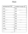
- FIG. 6 depicts one example of the above-mentioned current table 13T.
- types of respective instructions Inst1, Inst2, ..., Inst8 are stored.
- 300, 200, ..., 250 [ ⁇ A] are stored, respectively, as consumption current values in cases where the corresponding arithmetic and logic units of the above-mentioned four arithmetic and logic units 14A through 14D execute the respective types of instructions.
- ⁇ P1 - 500[ ⁇ A] is set as a current change limit value (which may be simply referred to as a limit value).
- the number of simultaneously issuable instructions is a maximum of 4 (#1, #2, #3 and #4) in the processor.
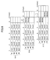
- FIG. 7 depicts instructions that have been issued at the past 5 cycles ("5" through “1") and instructions issuable at the present cycle "0", at each of points of time S1, S2 and S3.
- FIG. 7 depicts that, at the point of time S1 on the top, no instructions have been issued during the past 5 cycles, and currently issuable instructions are Inst1, Inst2, Inst3 and Inst4.
- a consumption current value per 1 instruction in a case where each of the simultaneously issuable instructions #1, #2, #3 and #4 is not executed is 20 [ ⁇ A].
- N 4 [cycles].
- the instruction issuance adjustment part 13A issues instructions that have been limited. In the example of FIG.
- the currently issuable instructions are the four instructions Inst5, Inst6, Inst3 and Inst4.
- the two instructions Inst3 and Inst4 are those for which issuance has been delayed at the preceding cycle as mentioned above, and the other two instructions Inst5 and Inst6 are instructions newly given to the instruction issuance control part 13X.
- the current change calculation part 13C determines the required number of dummy instructions, and gives it to the instruction issuance adjustment part 13A.
- an instruction of the required number of dummy instructions 2 is indicated to the instruction issuance adjustment part 13A so that two dummy instructions (dummy and dummy) are to be issued as instructions #3 and #4 of simultaneously issuable instructions.
- the instruction issuance adjustment part 13A issues two dummy instructions (dummy and dummy) as instructions #3 and #4 of simultaneously issuable instructions (point of time S13 on the bottom of FIG. 8 ).
- FIGs. 9 through 14 flowcharts for illustrating operations of instruction issuance control based on a consumption current change in the processor according to the above-described embodiment will be described.
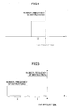
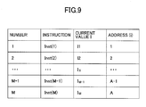
- FIG. 9 depicts relationships between respective consumption current values I of instructions Inst(1), Inst(2), ..., Inst(M) given to the instruction issuance control part 13X from the decoder 12 and addresses (i) in the program.
- the consumption current values I are obtained from the current table 13T such as that depicted in FIG. 6 .
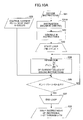
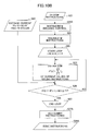
- FIG. 10A is an operation flowchart (No. 1), for when a consumption current increases, according to the monitoring method 1.
- step S21 of FIG. 10A instructions fetched from the instruction cache 11 are decoded by the decoder 12.
- steps S21R, S22 the instruction issuance control functional part 13R selects M simultaneously issuable instructions Inst(1), Inst(2), ..., Inst(M) from decoded instructions.
- step S24 a sum P(t) of consumption currents is calculated for the instructions Inst(1), Inst(2), ..., Inst(i) from the first through i-th of the above-mentioned M instructions, by the calculation part 13CC of the current change calculation part 13C.
- step S25 the calculation part 13CC of the current change calculation part 13C calculates the average value P(t-1, t-N) of the consumption current for the past N cycles.
- step S26 the above-mentioned sum P(t) of consumption currents up to the i-th instruction and a value obtained from adding the above-mentioned limit value ⁇ P1 to the average value P(t-1, t-N) of the past N cycles are compared.
- the above-mentioned loop operations are repeated. It is noted that the initial value of i is M, and at first, the sum P(t) of consumption currents up to the i-th instruction is the consumption currents for the M instructions.
- the instruction issuance adjustment part 13A issues instructions to the corresponding ones of the arithmetic and logic units 14A, 14B, 14C and 14D according to the priority order as mentioned above.
- the priority order includes a priority order among plural instructions for a case where there are the plural instructions that are simultaneously issuable.
- step S28 information concerning the finally selected instructions is given to the instruction issuance adjustment part 13A.
- the instruction issuance adjustment part 13A issues the finally selected 1 through i-th instructions to the arithmetic and logic units 14A, 14B, 14C and 14D at the present cycle (step S28). It is noted that Ix in step S24 denotes a consumption current value per each instruction at the present cycle (see FIG. 9 ).
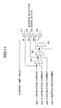
- FIG. 11 a circuit of FIG. 11 may be used, for example.
- the circuit of FIG. 11 has adders A1, A2 and A3, and comparators C1, C2, C3 and C4.
- the limit value ⁇ P1 is input to one inputs of the respective comparators C1, C2, C3 and C4.
- 4 instructions an instruction of addr1, an instruction of addr2, an instruction of addr3 and an instruction of addr4.
- a similar circuit configuration may be applied even when the number of issuable instructions becomes 5 or more.
- instruction of addr1, instruction of addr2, instruction of addr3 and instruction of addr4 may be, for example, an addition (ADD) instruction and a subtraction (SUB) instruction as arithmetic operations, and an AND instruction and an OR instruction as logic operations, and/or the like.
- ADD addition
- SUB subtraction
- the adder A1 obtains the sum of the consumption currents for total two instructions of the instruction of addr1 and instruction of addr2.
- the adder A2 obtains the sum of the output of the adder A1 and the consumption current for the instruction of addr3, i.e., obtains the sum of the consumption currents for the total three instructions of addr1, addr2 and addr3.
- the adder A3 obtains the sum of the output of the adder A2 and the consumption current for the instruction of addr4, i.e., obtains the sum of the consumption currents for the total four instructions of addr1, addr2, addr3 and addr4.
- the comparators C1, C2, C3 and C4 compare the respective ones of the consumption current for the instruction of addr1, the output of the adder A1, the output of the adder A2 and the output of the adder A3 with ⁇ P1. That is, the comparator C1 compares the consumption current P(t) concerning the instruction addr1 with ⁇ P1, and the comparator C2 compares the consumption current P(t) of the sum concerning the respective instructions addr1 and addr2 with ⁇ P1.
- the comparator C3 compares the consumption current P(t) of the sum concerning the respective instructions addr1, addr2 and addr3 with ⁇ P1
- the comparator C4 compares the consumption current P(t) of the sum concerning the respective instructions addr1, addr2, addr3 and addr4 with ⁇ P1.
- FIG. 10B is an operation flowchart (No. 2) for when a consumption current increases, according to the monitoring method 1.
- the operation flowchart (No. 2) of FIG. 10B depicts a method different from the above-described operation flowchart of FIG. 10A .
- steps S21 through S27 are the same as step S21 through S27 in the flowchart (No. 1) of FIG. 10A , and duplicate description will be omitted.
- a dummy instruction may be added in step S27A.
- step S27 the loop operations are finished when P(t) is equal to or less than the value obtained from adding the above-mentioned limit value ⁇ P1 to the average current value P(t-1, t-N) of the past N cycles (YES).
- P(t) is equal to or less than the value obtained from adding the above-mentioned limit value ⁇ P1 to the average current value P(t-1, t-N) of the past N cycles (YES).
- the above-mentioned P(t) is smaller than the average current value P(t-1, t-N) of the past N cycles, i.e., the consumption current will decrease, in a case where the above-mentioned limit value ⁇ P1 is small, or the like.
- the dummy instruction of the most suitable consumption current may be appropriately selected from the plural dummy instructions having different consumption currents, and may be added.
- the dummy instruction is added in step S27A to the 1 through i-th instructions finally selected in the loop operations of the above-mentioned steps S23, S24, S25, S26 and S27.
- information indicating the instructions to be issued is given to the instruction issuance adjustment part 13A.
- the instruction issuance adjustment part 13A issues the instructions indicated by the given information to the arithmetic and logic units 14A, 14B, 14C and 14D at the present cycle (step S28A).
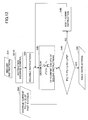
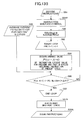
- FIG. 12 is an operation flowchart for when a consumption current decreases, according to the monitoring method 1.
- step S41 instructions fetched from the instruction cache 11 are decoded by the decoder 12.
- steps S41R and S42 the decoded instructions are given to the instruction issuance control functional part 13R of the instruction issuance control part 13X, and M simultaneously issuable instructions Inst(1), Inst(2), ..., Inst(M) are selected.
- the instruction issuance control part 13X carries out loop operations of steps S43, S45 and S46.
- step S46 the number of dummy instructions to be issued is increased by 1 in sequence, and the loop operations are finished when a determination result of step S45 becomes YES.
- step S43 the calculation part 13CC of the current change calculation part 13C calculates the sum P(t) of the consumption currents for the above-mentioned M instructions Inst(1), Inst(2), ..., Inst(M) and the dummy instructions added in step S46.
- step S44 the calculation part 13CC of the current change calculation part 13C calculates the average current value P(t-1, t-N) for the past N cycles.
- step S45 the sum P(t) of the consumption currents for the issuable instructions and the dummy instructions, and the value obtained from subtracting the above-mentioned limit value ⁇ P2 from the average current value P(t-1, t-N) for the past N cycles are compared.
- the loop operations are repeated until the sum P(t) of the consumption currents for the issuable instructions and the dummy instructions becomes greater than or equal to the value obtained from subtracting the above-mentioned limit value ⁇ P2 from the average current value P(t-1, t-N) for the past N cycles (YES).
- a number of dummy instructions to be issued i.e., "the required number of dummy instructions to be issued" is determined that the consumption current value P(t) obtained from adding dummy instructions as appropriate may be greater than or equal to the value obtained from subtracting the above-mentioned limit value ⁇ P2 from the average current value P(t-1, t-N) for the past N cycles.
- the thus obtained required number of dummy instructions to be issued is given to the instruction issuance adjustment part 13A.
- the instruction issuance adjustment part 13A issues the instructions obtained from adding the required number of dummy instructions to be issued to the issuable instructions, to the arithmetic and logic units 14A, 14B, 14C and 14D at the present cycle (step S47).
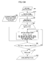
- FIG. 13A is an operation flowchart (No. 1) for when a consumption current increases, according to the monitoring method 2.
- step S61 of FIG. 13A instructions fetched from the instruction cache 11 are decoded by the decoder 12.
- steps S61R, S62 the decoded instructions are transferred to the instruction issuance control functional part 13R of the instruction issuance control part 13X, and M simultaneously issuable instructions Inst(1), Inst(2), ..., Inst(M) are selected.
- step S64 the sum P(t) of the consumption currents is calculated for the instructions Inst(1), Inst(2), ..., Inst(i) from the first through i-th of the above-mentioned M instructions, by the calculation part 13CC of the current change calculation part 13C. Then, the average value P(t, t-N+1) of the consumption current for the present and past N cycles to which the consumption current P(t) of the present cycle has been added is obtained. In step S65, the calculation part 13CC of the current change calculation part 13C calculates the average value P(t-N, t-2N+1) of the consumption current for the further past N cycles.
- step S66 the above-mentioned average value P(t, t-N+1) of the consumption current for the present and past N cycles to which the present cycle has been added and the value obtained from adding the above-mentioned limit value ⁇ P1 to the average current value (t-N, t-2N+1) for the further past N cycles are compared.
- the loop operations are continued until the average value P(t, t-N+1) of the consumption current for the present and past N cycles becomes equal to or less than the value obtained from adding the above-mentioned limit value ⁇ P1 to the average current value (t-N, t-2N+1) for the further past N cycles (YES).
- the initial value of i is M, and at first, the sum P(t) of consumption currents up to the i-th instruction is the consumption currents for the M instructions.
- the average current value P(t, t-N+1) of the present and past N cycles is equal to or less than the value obtained from adding the above-mentioned limit value ⁇ P1 to the average current value P(t-N, t-2N+1) for the further past N cycles (YES)
- the instruction issuance adjustment part 13A issues the instructions to the corresponding ones of the arithmetic and logic units 14A, 14B, 14C and 14D according to the priority order as mentioned above.
- instructions are removed one by one, from those having the larger addresses in sequence, and are removed until the calculated average current value P(t, t-N+1) for the present and past N cycles becomes equal to or less than the value obtained from adding the above-mentioned limit value ⁇ P1 to the average current value P(t-N, t-2N+1) for the further past N cycles.
- instructions are selected, from those having the smaller addresses in sequence, and the (1 through i-th) instructions up to immediately before the average current value P(t, t-N+1) for the present and past N cycles exceeds the value obtained from adding the above-mentioned limit value ⁇ P1 to the average current value P(t-N, t-2N+1) for the further past N cycles are finally selected.
- information concerning the finally selected instructions is given to the instruction issuance adjustment part 13A.
- the instruction issuance adjustment part 13A issues the finally selected 1 through i-th instructions to the arithmetic and logic units 14A, 14B, 14C and 14D at the present cycle (step S68).
- FIG. 13B is an operation flowchart (No. 2) for when a consumption current increases, according to the monitoring method 2.
- the operation flowchart (No. 2) depicts a method different from the above-described operation flowchart (No. 1) of FIG. 13A .
- steps S61 through S67 are the same as step S61 through S67 in the flowchart (No. 1) of FIG. 13A , and duplicate description will be omitted.
- a dummy instruction may be added in step S67A.
- step S67 the loop operations are finished when the average current value P(t, t-N+1) for the present and past N cycles is equal to or less than the value obtained from adding the above-mentioned limit value ⁇ P1 to the average current value P(t-N, t-2N+1) for the further past N cycles.
- the above-mentioned average current value P(t, t-N+1) for the present and past N cycles is less than the average current value P(t-N, t-2N+1) for the further past N cycles, i.e., the consumption current will decrease, in a case where the above-mentioned limit value ⁇ P1 is small or the like.
- the dummy instruction of the most suitable consumption current may be appropriately selected from the plural dummy instructions having different consumption currents, and may be added.
- the dummy instruction is added in step S67A to the 1 through i-th instructions finally selected in the loop operations of the above-mentioned steps S63, S64, S66 and S67.
- the instruction issuance adjustment part 13A issues the instructions indicated by the given information, to the arithmetic and logic units 14A, 14B, 14C and 14D at the present cycle (step S68A).
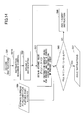
- FIG. 14 is a flowchart for when a consumption current decreases, according to the monitoring method 2.
- step S81 instructions fetched from the instruction cache 11 are decoded by the decoder 12.
- steps S81R and S82 the decoded instructions are given to the instruction issuance control functional part 13R of the instruction issuance control part 13X, and M simultaneously issuable instructions Inst(1), Inst(2), ..., Inst(M) are selected.
- the instruction issuance control part 13X carries out loop operations of steps S83, S85 and S86.
- step S86 the number of dummy instructions to be issued is increased by 1 in sequence, and the loop operations are finished when a determination result of step S85 becomes YES.
- step S83 the calculation part 13CC of the current change calculation part 13C calculates the sum P(t) of the consumption currents for the above-mentioned M instructions Inst(1), Inst(2), ..., Inst(M) and the dummy instructions added in step S46. Further, the average value P(t, t-N+1) of the consumption current for the present and past N cycles to which the consumption current P(t) of the present cycle has been added is obtained. In step S84, the calculation part 13CC of the current change calculation part 13C calculates the average value P(t-N, t-2N+1) of the consumption current for the further past N cycles.
- step S85 the average current value P(t, t-N+1) for the present and past N cycles to which the present cycle has been added and the value obtained from subtracting the above-mentioned limit value ⁇ P2 from the average current value (t-N, t-2N+1) for the further past N cycles are compared.
- the loop operations are continued until the average current value P(t, t-N+1) for the present and past N cycles becomes greater than or equal to the value obtained from subtracting the above-mentioned limit value ⁇ P2 from the average current value (t-N, t-2N+1) for the further past N cycles (YES).
- dummy instructions are added one by one so that the average current value P(t, t-N+1) for the present and past N cycles to which the consumption current at the present cycle has been added, to which the required number of dummy instructions have been added, becomes greater than or equal to the value obtained from subtracting the above-mentioned limit value ⁇ P2 from the average current value (t-N, t-2N+1) for the further past N cycles (step S86).
- the thus obtained number of the required dummy instructions to be issued is given to the instruction issuance adjustment part 13A.
- the instruction issuance adjustment part 13A issues the instructions obtained from adding the required number of dummy instructions to be issued to the issuable instructions, to the arithmetic and logic units 14A, 14B, 14C and 14D at the present cycle (step S87).
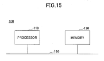
- FIG. 15 is a block diagram for illustrating a hardware configuration example of an information processing apparatus such as a server to which the above-mentioned processor according to the embodiment is applicable.
- the information processing apparatus includes a processor 110, a memory 120 as a storage unit, and a bus 130 that connects the processor 110 and the memory 120.
- the memory 120 stores a program in which instructions that the processor 110 executes are written, data which is a target on which the instructions are executed, data as results of execution of the instructions, and so forth.
- the processor 110 one having the configuration depicted in FIG. 2 may be applied. In this case, an instruction cache 11 of the processor depicted in FIG.
- the instruction issuance control part 13X has the same configuration as the instruction issuance control part 13X in the processor according to the embodiment described above with FIGs. 2 through 14 .
Landscapes
- Engineering & Computer Science (AREA)
- Theoretical Computer Science (AREA)
- Physics & Mathematics (AREA)
- General Engineering & Computer Science (AREA)
- General Physics & Mathematics (AREA)
- Power Sources (AREA)
- Advance Control (AREA)
- Executing Machine-Instructions (AREA)
Applications Claiming Priority (1)
| Application Number | Priority Date | Filing Date | Title |
|---|---|---|---|
| PCT/JP2009/070854 WO2011074059A1 (ja) | 2009-12-14 | 2009-12-14 | 演算処理装置、情報処理装置及びその制御方法 |
Publications (1)
| Publication Number | Publication Date |
|---|---|
| EP2515200A1 true EP2515200A1 (en) | 2012-10-24 |
Family
ID=44166861
Family Applications (1)
| Application Number | Title | Priority Date | Filing Date |
|---|---|---|---|
| EP09852255A Withdrawn EP2515200A1 (en) | 2009-12-14 | 2009-12-14 | Arithmetic processing device, information processing device, and method for controlling same |
Country Status (5)
| Country | Link |
|---|---|
| US (1) | US20120254595A1 (ja) |
| EP (1) | EP2515200A1 (ja) |
| JP (1) | JP5283762B2 (ja) |
| CN (1) | CN102652297A (ja) |
| WO (1) | WO2011074059A1 (ja) |
Cited By (3)
| Publication number | Priority date | Publication date | Assignee | Title |
|---|---|---|---|---|
| EP2808756A1 (en) * | 2013-04-18 | 2014-12-03 | Intel Corporation | Method and apparatus to control current transients in a processor |
| EP2887181A1 (en) * | 2013-12-23 | 2015-06-24 | Intel Corporation | Method and apparatus to control current transients in a processor |
| EP4202662A1 (en) * | 2021-12-23 | 2023-06-28 | INTEL Corporation | Adaptive dynamic dispatch of micro-operations |
Families Citing this family (18)
| Publication number | Priority date | Publication date | Assignee | Title |
|---|---|---|---|---|
| US8555095B2 (en) | 2010-07-26 | 2013-10-08 | Apple Inc. | Methods and systems for dynamically controlling operations in a non-volatile memory to limit power consumption |
| WO2012153377A1 (ja) * | 2011-05-06 | 2012-11-15 | 富士通株式会社 | 半導体集積回路およびその制御方法 |
| JP5946251B2 (ja) | 2011-07-06 | 2016-07-06 | ルネサスエレクトロニクス株式会社 | 半導体装置およびシステム |
| JP5806529B2 (ja) * | 2011-07-06 | 2015-11-10 | ルネサスエレクトロニクス株式会社 | 半導体装置、それを用いた無線通信端末、及びクロック周波数制御方法 |
| US9009451B2 (en) | 2011-10-31 | 2015-04-14 | Apple Inc. | Instruction type issue throttling upon reaching threshold by adjusting counter increment amount for issued cycle and decrement amount for not issued cycle |
| US9430242B2 (en) * | 2012-04-02 | 2016-08-30 | Nvidia Corporation | Throttling instruction issue rate based on updated moving average to avoid surges in DI/DT |
| JP2014048972A (ja) * | 2012-08-31 | 2014-03-17 | Fujitsu Ltd | 処理装置、情報処理装置、及び消費電力管理方法 |
| JP6036540B2 (ja) * | 2013-05-17 | 2016-11-30 | 富士通株式会社 | 半導体装置および半導体装置の制御方法 |
| US20150033045A1 (en) * | 2013-07-23 | 2015-01-29 | Apple Inc. | Power Supply Droop Reduction Using Feed Forward Current Control |
| US10241798B2 (en) * | 2013-09-20 | 2019-03-26 | Nvidia Corporation | Technique for reducing voltage droop by throttling instruction issue rate |
| US10160342B2 (en) * | 2016-03-29 | 2018-12-25 | GM Global Technology Operations LLC | Dynamic adjustment of battery current limits based on usage |
| US10345883B2 (en) * | 2016-05-31 | 2019-07-09 | Taiwan Semiconductor Manufacturing Co., Ltd. | Power estimation |
| US10175748B2 (en) * | 2017-01-05 | 2019-01-08 | Nuvoton Technology Corporation | System, method and computer program product for improved regulation of an electrical device's consumption of power from an external power supply |
| US10649518B2 (en) * | 2017-01-26 | 2020-05-12 | Ati Technologies Ulc | Adaptive power control loop |
| US10719320B2 (en) * | 2017-07-31 | 2020-07-21 | Intel Corporation | Power noise injection to control rate of change of current |
| US11073884B2 (en) | 2017-11-15 | 2021-07-27 | International Business Machines Corporation | On-chip supply noise voltage reduction or mitigation using local detection loops |
| JP7200507B2 (ja) * | 2018-06-06 | 2023-01-10 | 富士通株式会社 | 半導体装置及び演算器の制御方法 |
| CN111309134B (zh) * | 2020-03-23 | 2020-12-22 | 上海燧原智能科技有限公司 | 一种负载电流调整方法、装置、电子设备及存储介质 |
Family Cites Families (11)
| Publication number | Priority date | Publication date | Assignee | Title |
|---|---|---|---|---|
| JP2504224B2 (ja) * | 1989-10-12 | 1996-06-05 | 三菱電機株式会社 | デ―タ処理装置 |
| JPH10207859A (ja) | 1989-12-15 | 1998-08-07 | Hitachi Ltd | 消費電力制御方法,半導体集積回路装置およびマイクロプロセッサ |
| US6564328B1 (en) * | 1999-12-23 | 2003-05-13 | Intel Corporation | Microprocessor with digital power throttle |
| US6636976B1 (en) * | 2000-06-30 | 2003-10-21 | Intel Corporation | Mechanism to control di/dt for a microprocessor |
| JP2004013820A (ja) | 2002-06-11 | 2004-01-15 | Matsushita Electric Ind Co Ltd | クロック制御回路 |
| JP2004287919A (ja) * | 2003-03-24 | 2004-10-14 | Mitsubishi Electric Corp | 演算装置及び制御装置及び演算処理装置及び演算方法及び演算プログラム |
| JP2004334641A (ja) * | 2003-05-09 | 2004-11-25 | Fujitsu Ltd | 情報処理装置および記録媒体、並びにプロセッサ |
| JP4185104B2 (ja) * | 2006-02-28 | 2008-11-26 | 株式会社東芝 | 情報機器及びその動作制御方法 |
| US7992017B2 (en) * | 2007-09-11 | 2011-08-02 | Intel Corporation | Methods and apparatuses for reducing step loads of processors |
| US20090182986A1 (en) * | 2008-01-16 | 2009-07-16 | Stephen Joseph Schwinn | Processing Unit Incorporating Issue Rate-Based Predictive Thermal Management |
| US7937563B2 (en) * | 2008-05-27 | 2011-05-03 | Advanced Micro Devices, Inc. | Voltage droop mitigation through instruction issue throttling |
-
2009
- 2009-12-14 JP JP2011545869A patent/JP5283762B2/ja not_active Expired - Fee Related
- 2009-12-14 WO PCT/JP2009/070854 patent/WO2011074059A1/ja active Application Filing
- 2009-12-14 CN CN2009801628922A patent/CN102652297A/zh active Pending
- 2009-12-14 EP EP09852255A patent/EP2515200A1/en not_active Withdrawn
-
2012
- 2012-06-12 US US13/494,604 patent/US20120254595A1/en not_active Abandoned
Non-Patent Citations (1)
| Title |
|---|
| See references of WO2011074059A1 * |
Cited By (5)
| Publication number | Priority date | Publication date | Assignee | Title |
|---|---|---|---|---|
| EP2808756A1 (en) * | 2013-04-18 | 2014-12-03 | Intel Corporation | Method and apparatus to control current transients in a processor |
| US9411395B2 (en) | 2013-04-18 | 2016-08-09 | Intel Corporation | Method and apparatus to control current transients in a processor |
| EP2887181A1 (en) * | 2013-12-23 | 2015-06-24 | Intel Corporation | Method and apparatus to control current transients in a processor |
| US10114435B2 (en) | 2013-12-23 | 2018-10-30 | Intel Corporation | Method and apparatus to control current transients in a processor |
| EP4202662A1 (en) * | 2021-12-23 | 2023-06-28 | INTEL Corporation | Adaptive dynamic dispatch of micro-operations |
Also Published As
| Publication number | Publication date |
|---|---|
| CN102652297A (zh) | 2012-08-29 |
| WO2011074059A1 (ja) | 2011-06-23 |
| JPWO2011074059A1 (ja) | 2013-04-25 |
| JP5283762B2 (ja) | 2013-09-04 |
| US20120254595A1 (en) | 2012-10-04 |
Similar Documents
| Publication | Publication Date | Title |
|---|---|---|
| EP2515200A1 (en) | Arithmetic processing device, information processing device, and method for controlling same | |
| US6834353B2 (en) | Method and apparatus for reducing power consumption of a processing integrated circuit | |
| EP2073097B1 (en) | Transitioning a processor package to a low power state | |
| US10423216B2 (en) | Asymmetric multi-core processor with native switching mechanism | |
| US7194643B2 (en) | Apparatus and method for an energy efficient clustered micro-architecture | |
| US7890738B2 (en) | Method and logical apparatus for managing processing system resource use for speculative execution | |
| TWI649693B (zh) | 用於控制推測向量運算效能的資料處理設備、方法及電腦程式產品 | |
| US8327120B2 (en) | Instructions with floating point control override | |
| US8762444B2 (en) | Fast condition code generation for arithmetic logic unit | |
| US7802241B2 (en) | Method for estimating processor energy usage | |
| US20160162293A1 (en) | Asymmetric processor with cores that support different isa instruction subsets | |
| JP3759729B2 (ja) | スペキュレーティブ・レジスタの調整 | |
| US20120159225A1 (en) | Processor with power control via instruction issuance | |
| US20060101291A1 (en) | System, method, and apparatus for reducing power consumption in a microprocessor | |
| Catthoor et al. | DVFS-Oriented Scenario Applications to Processor Architectures | |
| US7124285B2 (en) | Peak power reduction when updating future file | |
| JPH07325788A (ja) | マルチプロセッサ | |
| Cheng et al. | Region-level approximate computation reuse for power reduction in multimedia applications | |
| Shim et al. | Power-aware branch logic: A hardware based technique for filtering access to branch logic | |
| CN112506642A (zh) | 信息处理设备、信息处理程序的记录介质和信息处理方法 |
Legal Events
| Date | Code | Title | Description |
|---|---|---|---|
| PUAI | Public reference made under article 153(3) epc to a published international application that has entered the european phase |
Free format text: ORIGINAL CODE: 0009012 |
|
| 17P | Request for examination filed |
Effective date: 20120709 |
|
| AK | Designated contracting states |
Kind code of ref document: A1 Designated state(s): AT BE BG CH CY CZ DE DK EE ES FI FR GB GR HR HU IE IS IT LI LT LU LV MC MK MT NL NO PL PT RO SE SI SK SM TR |
|
| DAX | Request for extension of the european patent (deleted) | ||
| STAA | Information on the status of an ep patent application or granted ep patent |
Free format text: STATUS: THE APPLICATION HAS BEEN WITHDRAWN |
|
| 18W | Application withdrawn |
Effective date: 20150108 |