EP2515031A1 - Système optique pour une distribution en éventail - Google Patents
Système optique pour une distribution en éventail Download PDFInfo
- Publication number
- EP2515031A1 EP2515031A1 EP12164833A EP12164833A EP2515031A1 EP 2515031 A1 EP2515031 A1 EP 2515031A1 EP 12164833 A EP12164833 A EP 12164833A EP 12164833 A EP12164833 A EP 12164833A EP 2515031 A1 EP2515031 A1 EP 2515031A1
- Authority
- EP
- European Patent Office
- Prior art keywords
- light
- lens
- source
- light source
- reflective surfaces
- Prior art date
- Legal status (The legal status is an assumption and is not a legal conclusion. Google has not performed a legal analysis and makes no representation as to the accuracy of the status listed.)
- Granted
Links
- 238000009826 distribution Methods 0.000 title claims abstract description 92
- 240000003380 Passiflora rubra Species 0.000 title claims abstract description 32
- 230000003287 optical effect Effects 0.000 title description 8
- 238000003491 array Methods 0.000 claims abstract description 15
- 239000000463 material Substances 0.000 claims description 28
- 238000000034 method Methods 0.000 claims description 13
- 230000005855 radiation Effects 0.000 abstract description 46
- 238000001429 visible spectrum Methods 0.000 abstract description 3
- 238000001228 spectrum Methods 0.000 abstract 1
- 238000005286 illumination Methods 0.000 description 14
- 229910052782 aluminium Inorganic materials 0.000 description 11
- XAGFODPZIPBFFR-UHFFFAOYSA-N aluminium Chemical compound [Al] XAGFODPZIPBFFR-UHFFFAOYSA-N 0.000 description 11
- 239000008393 encapsulating agent Substances 0.000 description 11
- 238000004519 manufacturing process Methods 0.000 description 4
- 238000000576 coating method Methods 0.000 description 3
- 230000000694 effects Effects 0.000 description 3
- 229920000642 polymer Polymers 0.000 description 3
- 238000002310 reflectometry Methods 0.000 description 3
- 238000004088 simulation Methods 0.000 description 3
- VYPSYNLAJGMNEJ-UHFFFAOYSA-N Silicium dioxide Chemical compound O=[Si]=O VYPSYNLAJGMNEJ-UHFFFAOYSA-N 0.000 description 2
- NIXOWILDQLNWCW-UHFFFAOYSA-N acrylic acid group Chemical group C(C=C)(=O)O NIXOWILDQLNWCW-UHFFFAOYSA-N 0.000 description 2
- 238000004364 calculation method Methods 0.000 description 2
- 238000005266 casting Methods 0.000 description 2
- 239000003989 dielectric material Substances 0.000 description 2
- 238000001746 injection moulding Methods 0.000 description 2
- 229920003229 poly(methyl methacrylate) Polymers 0.000 description 2
- 239000004926 polymethyl methacrylate Substances 0.000 description 2
- 229910052709 silver Inorganic materials 0.000 description 2
- 239000004332 silver Substances 0.000 description 2
- 238000001771 vacuum deposition Methods 0.000 description 2
- 235000017060 Arachis glabrata Nutrition 0.000 description 1
- 244000105624 Arachis hypogaea Species 0.000 description 1
- 235000010777 Arachis hypogaea Nutrition 0.000 description 1
- 235000018262 Arachis monticola Nutrition 0.000 description 1
- 229920000089 Cyclic olefin copolymer Polymers 0.000 description 1
- 239000004713 Cyclic olefin copolymer Substances 0.000 description 1
- 239000004593 Epoxy Substances 0.000 description 1
- 239000004793 Polystyrene Substances 0.000 description 1
- HCHKCACWOHOZIP-UHFFFAOYSA-N Zinc Chemical compound [Zn] HCHKCACWOHOZIP-UHFFFAOYSA-N 0.000 description 1
- 239000000853 adhesive Substances 0.000 description 1
- 230000001070 adhesive effect Effects 0.000 description 1
- 238000002048 anodisation reaction Methods 0.000 description 1
- 230000009286 beneficial effect Effects 0.000 description 1
- 239000000919 ceramic Substances 0.000 description 1
- 239000011248 coating agent Substances 0.000 description 1
- 229910052681 coesite Inorganic materials 0.000 description 1
- 239000003086 colorant Substances 0.000 description 1
- 238000000748 compression moulding Methods 0.000 description 1
- 239000004020 conductor Substances 0.000 description 1
- 229910052906 cristobalite Inorganic materials 0.000 description 1
- 230000007423 decrease Effects 0.000 description 1
- 230000001419 dependent effect Effects 0.000 description 1
- 238000010586 diagram Methods 0.000 description 1
- 238000009713 electroplating Methods 0.000 description 1
- 239000011521 glass Substances 0.000 description 1
- 230000017525 heat dissipation Effects 0.000 description 1
- 238000003754 machining Methods 0.000 description 1
- 229910052751 metal Inorganic materials 0.000 description 1
- 239000002184 metal Substances 0.000 description 1
- 238000000465 moulding Methods 0.000 description 1
- 230000037361 pathway Effects 0.000 description 1
- 235000020232 peanut Nutrition 0.000 description 1
- 229920000515 polycarbonate Polymers 0.000 description 1
- 239000004417 polycarbonate Substances 0.000 description 1
- 229920001296 polysiloxane Polymers 0.000 description 1
- 229920002223 polystyrene Polymers 0.000 description 1
- 238000003825 pressing Methods 0.000 description 1
- 230000001681 protective effect Effects 0.000 description 1
- 238000007493 shaping process Methods 0.000 description 1
- 239000000377 silicon dioxide Substances 0.000 description 1
- 229910052682 stishovite Inorganic materials 0.000 description 1
- 239000000126 substance Substances 0.000 description 1
- 229910052905 tridymite Inorganic materials 0.000 description 1
- XLYOFNOQVPJJNP-UHFFFAOYSA-N water Substances O XLYOFNOQVPJJNP-UHFFFAOYSA-N 0.000 description 1
- 229910052725 zinc Inorganic materials 0.000 description 1
- 239000011701 zinc Substances 0.000 description 1
Images


Classifications
-
- F—MECHANICAL ENGINEERING; LIGHTING; HEATING; WEAPONS; BLASTING
- F21—LIGHTING
- F21V—FUNCTIONAL FEATURES OR DETAILS OF LIGHTING DEVICES OR SYSTEMS THEREOF; STRUCTURAL COMBINATIONS OF LIGHTING DEVICES WITH OTHER ARTICLES, NOT OTHERWISE PROVIDED FOR
- F21V13/00—Producing particular characteristics or distribution of the light emitted by means of a combination of elements specified in two or more of main groups F21V1/00 - F21V11/00
- F21V13/02—Combinations of only two kinds of elements
- F21V13/04—Combinations of only two kinds of elements the elements being reflectors and refractors
-
- F—MECHANICAL ENGINEERING; LIGHTING; HEATING; WEAPONS; BLASTING
- F21—LIGHTING
- F21S—NON-PORTABLE LIGHTING DEVICES; SYSTEMS THEREOF; VEHICLE LIGHTING DEVICES SPECIALLY ADAPTED FOR VEHICLE EXTERIORS
- F21S4/00—Lighting devices or systems using a string or strip of light sources
- F21S4/20—Lighting devices or systems using a string or strip of light sources with light sources held by or within elongate supports
- F21S4/28—Lighting devices or systems using a string or strip of light sources with light sources held by or within elongate supports rigid, e.g. LED bars
-
- F—MECHANICAL ENGINEERING; LIGHTING; HEATING; WEAPONS; BLASTING
- F21—LIGHTING
- F21V—FUNCTIONAL FEATURES OR DETAILS OF LIGHTING DEVICES OR SYSTEMS THEREOF; STRUCTURAL COMBINATIONS OF LIGHTING DEVICES WITH OTHER ARTICLES, NOT OTHERWISE PROVIDED FOR
- F21V29/00—Protecting lighting devices from thermal damage; Cooling or heating arrangements specially adapted for lighting devices or systems
- F21V29/50—Cooling arrangements
- F21V29/502—Cooling arrangements characterised by the adaptation for cooling of specific components
- F21V29/505—Cooling arrangements characterised by the adaptation for cooling of specific components of reflectors
-
- F—MECHANICAL ENGINEERING; LIGHTING; HEATING; WEAPONS; BLASTING
- F21—LIGHTING
- F21V—FUNCTIONAL FEATURES OR DETAILS OF LIGHTING DEVICES OR SYSTEMS THEREOF; STRUCTURAL COMBINATIONS OF LIGHTING DEVICES WITH OTHER ARTICLES, NOT OTHERWISE PROVIDED FOR
- F21V29/00—Protecting lighting devices from thermal damage; Cooling or heating arrangements specially adapted for lighting devices or systems
- F21V29/50—Cooling arrangements
- F21V29/70—Cooling arrangements characterised by passive heat-dissipating elements, e.g. heat-sinks
- F21V29/71—Cooling arrangements characterised by passive heat-dissipating elements, e.g. heat-sinks using a combination of separate elements interconnected by heat-conducting means, e.g. with heat pipes or thermally conductive bars between separate heat-sink elements
-
- F—MECHANICAL ENGINEERING; LIGHTING; HEATING; WEAPONS; BLASTING
- F21—LIGHTING
- F21V—FUNCTIONAL FEATURES OR DETAILS OF LIGHTING DEVICES OR SYSTEMS THEREOF; STRUCTURAL COMBINATIONS OF LIGHTING DEVICES WITH OTHER ARTICLES, NOT OTHERWISE PROVIDED FOR
- F21V29/00—Protecting lighting devices from thermal damage; Cooling or heating arrangements specially adapted for lighting devices or systems
- F21V29/50—Cooling arrangements
- F21V29/70—Cooling arrangements characterised by passive heat-dissipating elements, e.g. heat-sinks
- F21V29/74—Cooling arrangements characterised by passive heat-dissipating elements, e.g. heat-sinks with fins or blades
- F21V29/76—Cooling arrangements characterised by passive heat-dissipating elements, e.g. heat-sinks with fins or blades with essentially identical parallel planar fins or blades, e.g. with comb-like cross-section
- F21V29/763—Cooling arrangements characterised by passive heat-dissipating elements, e.g. heat-sinks with fins or blades with essentially identical parallel planar fins or blades, e.g. with comb-like cross-section the planes containing the fins or blades having the direction of the light emitting axis
-
- F—MECHANICAL ENGINEERING; LIGHTING; HEATING; WEAPONS; BLASTING
- F21—LIGHTING
- F21V—FUNCTIONAL FEATURES OR DETAILS OF LIGHTING DEVICES OR SYSTEMS THEREOF; STRUCTURAL COMBINATIONS OF LIGHTING DEVICES WITH OTHER ARTICLES, NOT OTHERWISE PROVIDED FOR
- F21V5/00—Refractors for light sources
- F21V5/007—Array of lenses or refractors for a cluster of light sources, e.g. for arrangement of multiple light sources in one plane
-
- F—MECHANICAL ENGINEERING; LIGHTING; HEATING; WEAPONS; BLASTING
- F21—LIGHTING
- F21V—FUNCTIONAL FEATURES OR DETAILS OF LIGHTING DEVICES OR SYSTEMS THEREOF; STRUCTURAL COMBINATIONS OF LIGHTING DEVICES WITH OTHER ARTICLES, NOT OTHERWISE PROVIDED FOR
- F21V5/00—Refractors for light sources
- F21V5/04—Refractors for light sources of lens shape
-
- G—PHYSICS
- G02—OPTICS
- G02B—OPTICAL ELEMENTS, SYSTEMS OR APPARATUS
- G02B27/00—Optical systems or apparatus not provided for by any of the groups G02B1/00 - G02B26/00, G02B30/00
- G02B27/09—Beam shaping, e.g. changing the cross-sectional area, not otherwise provided for
- G02B27/0938—Using specific optical elements
- G02B27/095—Refractive optical elements
-
- H—ELECTRICITY
- H01—ELECTRIC ELEMENTS
- H01L—SEMICONDUCTOR DEVICES NOT COVERED BY CLASS H10
- H01L33/00—Semiconductor devices with at least one potential-jump barrier or surface barrier specially adapted for light emission; Processes or apparatus specially adapted for the manufacture or treatment thereof or of parts thereof; Details thereof
- H01L33/48—Semiconductor devices with at least one potential-jump barrier or surface barrier specially adapted for light emission; Processes or apparatus specially adapted for the manufacture or treatment thereof or of parts thereof; Details thereof characterised by the semiconductor body packages
- H01L33/52—Encapsulations
- H01L33/54—Encapsulations having a particular shape
-
- F—MECHANICAL ENGINEERING; LIGHTING; HEATING; WEAPONS; BLASTING
- F21—LIGHTING
- F21W—INDEXING SCHEME ASSOCIATED WITH SUBCLASSES F21K, F21L, F21S and F21V, RELATING TO USES OR APPLICATIONS OF LIGHTING DEVICES OR SYSTEMS
- F21W2131/00—Use or application of lighting devices or systems not provided for in codes F21W2102/00-F21W2121/00
- F21W2131/10—Outdoor lighting
- F21W2131/103—Outdoor lighting of streets or roads
-
- F—MECHANICAL ENGINEERING; LIGHTING; HEATING; WEAPONS; BLASTING
- F21—LIGHTING
- F21Y—INDEXING SCHEME ASSOCIATED WITH SUBCLASSES F21K, F21L, F21S and F21V, RELATING TO THE FORM OR THE KIND OF THE LIGHT SOURCES OR OF THE COLOUR OF THE LIGHT EMITTED
- F21Y2103/00—Elongate light sources, e.g. fluorescent tubes
- F21Y2103/10—Elongate light sources, e.g. fluorescent tubes comprising a linear array of point-like light-generating elements
-
- F—MECHANICAL ENGINEERING; LIGHTING; HEATING; WEAPONS; BLASTING
- F21—LIGHTING
- F21Y—INDEXING SCHEME ASSOCIATED WITH SUBCLASSES F21K, F21L, F21S and F21V, RELATING TO THE FORM OR THE KIND OF THE LIGHT SOURCES OR OF THE COLOUR OF THE LIGHT EMITTED
- F21Y2105/00—Planar light sources
- F21Y2105/10—Planar light sources comprising a two-dimensional array of point-like light-generating elements
-
- F—MECHANICAL ENGINEERING; LIGHTING; HEATING; WEAPONS; BLASTING
- F21—LIGHTING
- F21Y—INDEXING SCHEME ASSOCIATED WITH SUBCLASSES F21K, F21L, F21S and F21V, RELATING TO THE FORM OR THE KIND OF THE LIGHT SOURCES OR OF THE COLOUR OF THE LIGHT EMITTED
- F21Y2115/00—Light-generating elements of semiconductor light sources
- F21Y2115/10—Light-emitting diodes [LED]
Definitions
- Embodiments of the present invention relate to radiation distribution systems, including optical systems that produce a batwing-type light distribution pattern.
- batwing refers to a light distribution whose luminous intensity is greater along a direction at a significant angle relative to the main axis of distribution rather than along a direction parallel to the main axis.
- the desirability of a batwing distribution is evident in many lighting applications, including, for example, roadway lighting in which most of the light should be distributed in a direction parallel to the roadway.
- FIG.1a shows various types of roadway illumination patterns named with a convention used by the Illuminating Engineering Society (IES). As shown, there are five common types of roadway illumination. Type I illumination is a direct illumination in two directions along the direction of the roadway (if the road is a single road) and/or in a straight directional pattern at a cross section as shown by the Type I-4-Way pattern. Type V describes an omni-directional lighting pattern across the entire intersection. Type II is similar to Type I, but the light fixture is mounted above a point displaced away from the center of the region to be illuminated. Type III illumination shows a different angled illumination from normal as compared to Type II, where the angle of illumination from normal is narrower to reflect a smaller coverage area. Type IV illumination has an even narrower angle of illumination from normal to create a different, smaller illumination area than either Type III or Type II.
- Type I illumination is a direct illumination in two directions along the direction of the roadway (if the road is a single road) and/or in a straight directional pattern at a cross section as shown
- FIG.1b shows a known generic light fixture 100 that is mounted at a height H above a surface 102 that is to be illuminated by the fixture 100.
- the main axis 104 starts at the fixture 100 and runs perpendicular to a plane containing surface 102.
- the light distribution on the surface is typically specified in terms of the illuminance I(x,y) measured in lumens/ft 2 .
- the distribution of the light emanating from the fixture is typically specified in terms of the luminous intensity P( ⁇ , ⁇ ) measured in a direction making an angle ⁇ relative to the main axis and lying in a plane that contains the main axis and is oriented at angle ⁇ , as shown in FIG.1b .
- the elliptical region 106 is substantially longer in one direction (along the x-axis) than in the other direction (along the y-axis). Outside the region 106 the illuminance falls off to a minimum level.
- the region 106 may be substantially symmetrical about the main axis in the x-direction of the pattern and either symmetrical (Type I) or asymmetrical (Types II, III, IV) along the y-direction.
- the 1/cos 3 ( ⁇ ) factor is less than about 1.3, and many such lighting applications can use conventional collimators to achieve acceptable uniformity.
- the illuminance is desired to be uniform out to values of ⁇ of 30° or more.
- the 1/cos 3 ( ⁇ ) factor at these angles rises sharply with ⁇ , reaching values much greater than 1 well before the illuminance factor drops off.
- the characteristic batwing shape of P( ⁇ ) is critical in these applications in order to achieve substantial illuminance uniformity.
- FIG.2 shows a uniform illuminance I(x,0) denoted as 204, extending ⁇ 50 ft in the x-direction of FIG.1 , and a uniform illuminance I(0,y) denoted as 208, extending -10 to +25 ft in the y-direction, with each illuminance falling off gradually outside those ranges.
- FIG.2 also shows the corresponding intensity distributions 202 and 206, both batwing distributions.
- the batwing distribution 202 is along the long x-axis of the region 106 (e.g., along the roadway in the street lighting application), and the batwing distribution 206 is along the perpendicular y-axis.
- Batwing luminaires are known in the prior art for use with incandescent and discharge lamps which are typically small sources emitting into a full spherical distribution. These sources are typically powerful enough such that one or two lamps can supply all the light needed for the entire fixture. Batwing optical systems for these sources typically use reflectors having asymmetric curvature, facets, or cut-off angles, as can be found in the prior art. Lenses are less common, but are also known, particularly Fresnel lenses or lenticular lenses. These prior art systems are adapted for incandescent and discharge lamps.
- LEDs light-emitting diodes
- batwing optical systems used for incandescent and discharge lamps are not designed for use with LEDs.
- LEDs are typically arranged in arrays that have a large overall area. LEDs also emit only into the forward hemisphere, not into a full spherical pattern. It is desirable to have an improved batwing optical system adapted for light sources with these emission characteristics, and specifically for, LEDs.
- a lens is disposed on a mount surface.
- the lens has a dielectric surface comprising a middle section having a center region that is tapered in from both sides and two rounded end sections, an end section on each side of the center section.
- At least one elongated reflective surface is disposed external to the lens and proximate to the lens.
- One embodiment of a light emitting diode (LED) array comprises the following elements.
- a plurality of LEDs is included, each of the LEDs at least partially covered by a lens.
- Each of a plurality of reflector bodies has two reflective surfaces running along a length of the reflector body. The reflective surfaces face outward, away from each other.
- the LEDs are arranged between any two of the reflector bodies such that a portion of the light emitted from the LEDs interacts with the reflective surfaces that face the LEDs.
- One embodiment of a scalable light source according to the present invention comprises the following elements.
- a plurality of linear light source sub-arrays is arranged to form a two-dimensional array.
- a plurality of lenses is included with a respective one of the lenses arranged to interact with each of the light sources.
- a plurality of reflector bodies is included with a respective one of the reflector bodies disposed on each of the longer sides of each linear light source sub-array.
- the reflector bodies comprise two elongated reflective surfaces that face away from each other.
- the lenses and the reflective surfaces are designed to interact with light emitted from the light sources such that the illuminance has a batwing distribution.
- One method for generating a light distribution pattern comprises the following steps.
- a light source is provided.
- Light emitted from the light source is redirected a first time with a lens that substantially envelopes the light source.
- a portion of the light is redirected a second time with two reflective surfaces disposed one on each side of said light source.
- the emitted light is distributed in a batwing pattern.
- FIG.1a is a series of diagrams showing some common roadway illumination patterns named with a convention used by the Illuminating Engineering Society (IES).
- FIG.1b is a perspective view of a generic light fixture known in the prior art, along with a generic coordinate system for describing a light distribution.
- FIG.2 shows two graphs of illuminance and luminous intensity as a function of distance in both axial directions relating to the light distribution of the known fixture in FIG.1 .
- FIGs.3a and 3b are three-dimensional perspective drawings of an embodiment of a radiation distribution system.
- FIG.4 is a cross-sectional view of an embodiment of a lens and a source.
- FIG.5 is a cross-sectional view of an embodiment of a lens and a source.
- FIG.6 is a cross-sectional view of an embodiment of a radiation distribution system.
- FIG.7 shows two graphs of illuminance as a function of both axial distances relating to an embodiment of a radiation distribution system.
- FIG.8 is a cross-sectional view of an embodiment of a lens and a source.
- FIGs.9a and 9b are perspective views of an embodiment of a lens; FIG.9c is a cross-sectional view of same.
- FIG.10a is a perspective view of an embodiment of a radiation distribution system; FIG.10b is a cross-sectional view of same.
- FIG.11 is a cross-sectional view of an embodiment of a radiation distribution system.
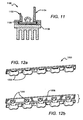
- FIGs.12a and 12b are perspective views an embodiment of a linear array of lenses and sources.
- FIG.13a is a perspective view of an embodiment of a radiation distribution system; FIG.13b is an exploded view of same.
- FIG.14a is a perspective view of an embodiment of a radiation distribution system; FIG.14b is a cross-sectional view of same.
- FIG.15a is a perspective view of an embodiment of a radiation distribution system; FIG.15b is a top plan view of same.
- Embodiments of the present invention as claimed provide a radiation distribution system that generates a batwing distribution of luminous intensity.
- the system is particularly suited for use with LEDs and LED arrays.
- One or more light sources are positioned beneath a specially shaped lens that substantially envelopes the source(s).
- the shape of the lens is similar to a half peanut shell, sliced along the longer direction (i.e., the x-direction).
- At least one elongated reflective surface is positioned proximate to the lens and parallel to an axis running through center of the lens in the longer direction. In one embodiment two such elongated reflective surfaces are placed facing each other on opposite sides of the lens.
- the light emitted from the source interacts with the enveloping lens first.
- the lens is made from an optically transmissive dielectric material.
- a dielectric interface formed by the boundary of the lens and the ambient material causes the light rays to be redirected, giving the light a first batwing distribution in the x-direction.
- the reflective surfaces redirect the incident light, further shaping it into a second batwing distribution in a direction orthogonal to x-direction (i.e., the y-direction).
- the resulting two-dimensional batwing distribution has several applications, such as surface street lighting, low-bay lights', and architectural lighting fixtures, for example.
- the batwing distribution can be tailored to a Type II roadway lighting pattern.
- first, second, etc. may be used herein to describe various elements, components, regions, layers and/or sections, these elements, components, regions, layers and/or sections should not be limited by these terms. These terms are only used to distinguish one element, component, region, layer or section from another. Thus, a first element, component, region, layer or section discussed below could be termed a second element, component, region, layer or section without departing from the teachings of the present invention.
- Embodiments of the invention are described herein with reference to cross-sectional view illustrations that are schematic illustrations of idealized embodiments of the invention. As such, variations from the shapes of the illustrations as a result, for example, of manufacturing techniques and/or tolerances are expected. Embodiments of the invention should not be construed as limited to the particular shapes of the regions illustrated herein but are to include deviations in shapes that result, for example, from manufacturing. Thus, the regions illustrated in the figures are schematic in nature and their shapes are not intended to illustrate the precise shape of a region of a device and are not intended to limit the scope of the invention, unless explicitly stated otherwise.
- FIGs.3a and 3b are three-dimensional perspective drawings, showing an embodiment of a radiation distribution system 300.
- FIG.3b contains a ray trace that models the behavior of emitted light as it interacts with elements of the system.
- the light rays are omitted so that the system may be viewed clearly.
- This particular embodiment comprises a lens 302 and two elongated reflective surfaces 304, 306 facing each other on opposite sides of the lens 302.
- a radiative source 308 (obscured from view in FIG.3a ) is disposed beneath the lens 302. Radiation emitted from the source 308 interacts with the lens 302 and the elongated surfaces 304, 306 to yield a batwing distribution.
- the radiative source 308 is disposed on a surface (not shown in FIGs.3a and 3b ).
- the surface can be a printed circuit board (PCB), for example.
- PCB printed circuit board
- a PCB allows the source 308 to be conveniently biased using an external power supply.
- the radiative source 308 comprises an LED (or a plurality of LEDs) that emits radiation in the visible spectrum (approx. 350-850nm).
- Other sources can be used, such as infrared emitters or ultraviolet emitters, for example.
- the radiative source 308 is almost completely enveloped by the lens 302.
- the lens 302 is made from a light transmissive dielectric material; the material may be transparent or translucent. Polymethyl methacrylate (PMMA or, commonly, acrylic) is an acceptable material, although many other materials can be used.
- the lens 302 has an exit surface 310 that may be shaped by known processes, such as casting or machining. In this particular embodiment, the exit surface 310 comprises a middle section 312 and two end sections 316 that have mirror-image symmetry. Indeed, the entire lens 302 has mirror-image symmetry as the lens 302 is symmetrical about both the longitudinal (x-z) axial plane and the transverse (y-z) axial plane. These two axial planes are shown in FIG.3a .
- a longitudinal x-axis lies within in the longitudinal plane.
- the middle section 312 has a center region 314 that is tapered in from both sides, making it narrower than adjacent portions of the end sections 316.
- the middle section 312 has a saddle-point on the surface 310 at the intersection of the longitudinal and transverse symmetry planes (i.e., at the center region 314).
- the end sections 316 are rounded as shown. Many different variations from the specific dimensions of the surface contours shown in FIGs.3a and 3b may be used to tailor the batwing distribution pattern.
- the exit surface 310 forms a dielectric interface with the material surrounding the lens (i.e., the ambient).
- the ambient material might be any material that surrounds the lens 302, such as air or water.
- the dimensions of the batwing distribution are determined, in part, by the index of refraction differential between the lens material and the ambient material. For larger differentials, the light will be refracted more dramatically when passing from the lens 302 into the ambient.
- lens 302 After the light exits lens 302, a portion of it continues unobstructed as emitted light. A portion of the light exiting the lens 302 at higher angles in the transverse directions (i.e. out the sides) interacts with the reflective surfaces 304, 306. Light that is incident on the reflective surfaces 304, 306 is redirected at an angle back toward the longitudinal axial plane as shown in FIG.3b .
- the reflective surfaces 304, 306 may be fabricated using any material that can be coated or formed to have a high specular reflectivity over the range of wavelengths that is emitted from the source 308. Some acceptable materials and fabrication techniques include extruded aluminum, machined aluminum, formed aluminum sheet metal, extruded polymers, molded polymers, cast aluminum, cast zinc and formed ceramic. To increase the reflectivity in the visible spectrum, the reflective surfaces 304, 306 may be polished and may also be coated for durability as well as reflectivity. Some typical coating processes include vacuum deposition of aluminum or silver, chemical or electroplating of aluminum or silver, and vacuum deposition of multilayer dielectric coatings.
- a reflective coating typically includes a protective overlayer, such as a transparent polymer, SiO, SiO 2 or an aluminum anodization layer. It may also be desirable to use a material having a high thermal conductivity. Such a material would help to dissipate generated heat away from the source 308, increasing its efficiency and lifetime.
- a protective overlayer such as a transparent polymer, SiO, SiO 2 or an aluminum anodization layer. It may also be desirable to use a material having a high thermal conductivity. Such a material would help to dissipate generated heat away from the source 308, increasing its efficiency and lifetime.
- FIG.4 illustrates a cross-sectional view lying in the longitudinal symmetry plane of a radiation distribution system 400.
- the source 402 is enveloped by a dielectric encapsulant 404. If the source is an LED, an encapsulant may be used to enhance the quantity of the emitted light and to physically protect the source from moisture, mechanical contact, etc.
- the encapsulant 404 is in contact with a lens 406 with no intervening air gap.
- the lens 406 can be fabricated by forming it directly on the encapsulant 404; for example, it may be molded or cast as a part of the encapsulant 404 using materials such as silicone or epoxy.
- the lens 406 can be formed separately using the same or a different material as the encapsulant 404 and then attached to the encapsulant 404 with an adhesive.
- the lens 406 has a middle section 408 with a center region 410 at its narrowest point and two rounded end sections 412.
- FIG.5 shows a cross-sectional view of an exemplary lens profile 500.
- the lens output surface is a surface of revolution formed by partially rotating the profile 500 about a rotational symmetry axis 504, parallel to the longitudinal axial plane.
- I x ⁇ 0 ⁇ I 0 x ⁇ 50 ⁇ ft I 0 ⁇ x - 50 ⁇ ft 10 ⁇ ft 50 ⁇ ft ⁇ x ⁇ 60 ⁇ ft 0 x ⁇ 60 ⁇ ft
- P x ⁇ I 0 25 ⁇ ft 2 ⁇ 1 cos 3 ⁇
- the 1/cos 3 ( ⁇ ) factor is more than 10, i.e., the luminous intensity at 63.4° is more than 10 times higher than the luminous intensity at 0°.
- the lens profile 500 can be calculated from P x ( ⁇ ) by assuming a source 502 located on or near the rotational symmetry axis 504.
- FIG.5 shows the profile 500 and some exemplary light rays.
- the lens profile 500 maps the source power distribution P source ( ⁇ source ) into the output distribution P x ( ⁇ )
- rays emitted from the source with small values of ⁇ source e.g., ray 506
- larger-angle source rays e.g., ray 508
- the lens both reduces the intensity at low angles and increases the intensity at high angles.
- the concave central section 510 diverges the small-angle rays, and the convex outer sections 512 converge the larger-angle rays.
- the profile ends at a maximum source collection angle ⁇ max .
- the detailed profile can be calculated by various means.
- the profile can be expressed as a polynomial in polar coordinates centered on the light source, and the terms in the polynomial can be optimized using Monte Carlo ray-tracing simulations.
- the desired output angle ⁇ for each source ray angle ⁇ source in terms of an angle output function ⁇ ( ⁇ source ).
- ⁇ ( ⁇ source ) there are various known methods for easily calculating the desired profile from such ray angle specifications.
- the profile can be calculated by any of these means, the resulting optical system performance can be simulated by Monte Carlo ray-tracing using a realistic extended source (not the simplified point source), and a new, compensated angle function ⁇ ( ⁇ source ) can be generated to correct the non-uniformities observed in the simulation.
- a realistic extended source not the simplified point source
- ⁇ ( ⁇ source ) can be generated to correct the non-uniformities observed in the simulation.
- I x ⁇ 0 ⁇ I 0 ⁇ ⁇ ⁇ 1 + a ⁇ x - 50 ⁇ ft 2 ⁇ x ⁇ 50 ⁇ ft I 0 ⁇ ⁇ ⁇ 1 + a ⁇ x - 50 ⁇ ft 10 ⁇ ft 50 ⁇ ft ⁇ x ⁇ 60 ⁇ ft 0 x ⁇ 60 ⁇ ft
- FIG.6 shows a cross-sectional view of a radiation distribution system 600.
- the system includes a lens 606 having an output surface that is a surface of rotation about a longitudinal axis passing through or at least near the light source 612.
- the cross-section of the system 600 is shown in the transverse symmetry plane of the lens 606, along with the projected angles in this plane of some sample rays.
- the reflector 602 intercepts any source rays with projected angles ranging from ⁇ 1 to ⁇ 2
- the reflector 604 intercepts source rays with projected angles ranging from ⁇ 3 to ⁇ 4 . Note that the source rays exiting with projected angles ⁇ 2 to ⁇ 3 are uncontrolled by the reflectors. The design must compensate for the uncontrolled light.
- the output light projected distribution P unc not controlled by the reflectors is approximately the projected source distribution P source for angles ⁇ between ⁇ 2 and ⁇ 3 .
- the reflector profile 602 is then calculated to map the source projected angles ⁇ 1 to ⁇ 2 into specified portions of the output distribution P cont ( ⁇ ).
- the profile 604 is calculated to map the source projected angles ⁇ 3 to ⁇ 4 into specified portions of the output distribution P cont ( ⁇ ). Specific methods of calculation resemble the methods described above for calculating the lens profile that maps source angles into the desired P x ( ⁇ ).
- the minimum value for the batwing distribution P y ( ⁇ ) is set by P source . This can be summarized as: P cont ⁇ ⁇ P source 0 cos 3 ⁇ ⁇
- the reflectors typically redirect most of the light collected into the higher desired values of ⁇ .
- the total power collected by the reflectors is limited to the power in the controlled angle ranges ⁇ 1 to ⁇ 2 and ⁇ 3 to ⁇ 4 . If the uncontrolled angle range ⁇ 2 to ⁇ 3 is too large, then there is too little power left for the reflectors to collect to satisfy Eq. 9. This limits the angle ranges and the level of uniformity that can be achieved.
- the total edge-to-edge range of ⁇ in the short axis is still preferably less than 90°, and the largest angle ⁇ in the short axis is preferably less than about 60° (i.e.,
- Each reflector can be designed to illuminate only a section of the output distribution.
- the reflector 602 illuminates primarily the right-hand output angles as shown by ray 608, and the reflector 604 illuminates primarily the left-hand output angles as shown by ray 610.
- the reflector 602 could also be designed to illuminate the left-hand output angles, in which case the reflector 604 would illuminate the right-hand output angles.
- each reflector surface could be designed to illuminate both left-hand and right-hand output angles. Each of these options would require different reflector profiles.
- FIG.7 shows the results of Monte Carlo raytrace simulations using two exemplary profiles as calculated above, with a simulated Cree 7090 XR-E LED light source.
- the figure shows two cross-sections of the simulated illuminance in footcandles (fc) per total lumen emitted by the source, on a planar surface 25 feet from the system.
- the illuminance per lumen data set 702 is in the longitudinal symmetry plane, and the illuminance per lumen data set 704 is in the transverse symmetry plane.
- FIG.8 Another embodiment of a radiation distribution system 800 is shown in Fig.8 .
- the figure shows a cross-section of a lens 802 in the longitudinal symmetry plane.
- the encapsulating medium 804 is in optical contact with a transparent dielectric light source dome 806.
- the lens 802 has a dielectric light entrance surface 808 opposite a light exit surface 810.
- the light entrance surface 808 includes a dome cavity 812 that fits over the light source dome 806.
- An exemplary light ray 814 emitted by the light source 816 is refracted in turn by the light source dome 806, the lens light entrance surface 808, and the lens light exit surface 810.
- all three refractions must be considered in order to ensure that the surfaces cooperate to produce the desired batwing distribution.
- the lens 802 can be fabricated by common dielectric forming processes such as casting, injection molding, and compression molding, for example.
- Some acceptable materials include glass, acrylic, polycarbonate, polystyrene, and cyclic olefin copolymer.
- FIGs. 9a-c show three views of an embodiment of a lens 900 adapted for these purposes.
- FIGs. 9a and 9b show two perspective views;
- FIG. 9c shows a cross-sectional view in the longitudinal symmetry plane.
- the light entrance surface 902 has been modified to create hollow regions 904 that significantly reduce the lens thickness. These regions 904 are shaped to minimize the total amount of material and total thickness variation, while still avoiding significant loss of light transmitted by the lens 900.
- a portion 906 of the light entrance surface is positioned at an angle ⁇ to the central axis 908. If ⁇ is too large, the lens thickness will not be appreciably reduced. If ⁇ is too small, the portion 906 will intercept too much of the emitted light.
- the light is distributed substantially inside a cone defined by a limiting angle ⁇ . In such a case, ⁇ is preferably similar to or slightly larger than ⁇ . For example, for the Cree XLamp 7090 LED, ⁇ is approximately 55-60°, and ⁇ may be advantageously chosen between 50° and 70°.
- the cross-sectional view shows the lens 900 positioned over a dome-shaped encapsulant 910.
- the light entrance surface 902 of this embodiment includes a dome cavity 912 designed to cooperate with the light source dome 910.
- the lens 900 also comprises positioning feet 914 that are integrally molded with the lens 900. As with the hollow regions 904, the feet 914 are preferably added to regions of the lens 900 that are positioned at angles greater than ⁇ relative to the axis 908, so that they intercept small amounts of the emitted light.
- FIGs. 10a and 10b show two views of another embodiment of a radiation distribution system 1000.
- FIG.10a is a perspective view
- FIG.10b is a cross-sectional view in the transverse symmetry plane of the lens 1002.
- the reflective surfaces 1004 and 1006 are much longer in the longitudinal direction than a single lens 1002.
- Additional lenses 1002 and sources 1008 may be positioned linearly between a single pair of elongated reflective surfaces 1004, 1006.
- multiple lenses 1002 can be molded as a single lens array, reducing molding cost and simplifying the assembly.
- the sources 1008 may be LEDs.
- a linear array of five sources 1008 can be soldered onto a single metal-core circuit board 1010.
- the circuit board 1010 is then attached to a backplane 1012, possibly aluminum or another material having high thermal conductivity.
- the backplane 1012 also provides mounting surfaces for reflector bodies 1014, 1016, which comprise the reflective surfaces 1004, 1006, respectively, and a heat sink 1018.
- the interface between the circuit board 1010 and the backplane 1012 may be filled with a thermal interface material layer 1020.
- the thermal interface material layer 1020 reduces the thermal resistance by minimizing or eliminating the air gaps between the circuit board 1010 and the backplane 1012. Minimum thermal resistance is achieved by ensuring that the interface material layer 1020 is a uniform thin layer. This may be done by applying pressure on the circuit board 1010 against the backplane 1012.
- the reflector bodies 1014, 1016 themselves can be pathways for thermal dissipation.
- the reflector bodies 1014, 1016 are preferably composed of a stiff, thermally conductive material such as aluminum, for example.
- the reflector bodies 1014, 1016 can thereby act as clamps to apply pressure to the circuit board 1010 against the backplane 1012, with clamping force supplied by bolting the two elements together or otherwise affixing them.
- the reflector bodies 1014, 1016 can also act as fins to dissipate heat away from the circuit board 1010. Thermal dissipation through the reflector bodies 1014, 1016, is most effective if thermal resistance from the circuit board 1010 to the reflector bodies 1014, 1016 is minimized by adding thermal interface material layers 1022, 1024.
- Layer 1022 is disposed between the circuit board 1010 and the reflector bodies 1014, 1016.
- Layer 1024 is disposed between the reflector bodies 1014, 1016 and the backplane 1012. The layers 1022, 1024 are compliant, so that the reflector bodies 1014, 1016 can still exert clamping force.
- FIG.11 shows another embodiment of a radiation distribution system 1100.
- the reflector bodies 1102, 1104 are integrally formed, onto the backplane 1106.
- the backplane 1106 and reflector bodies 1102, 1104 can be extruded as a single component.
- thermal resistance from the backplane 1106 to the reflector bodies 1102, 1104 is minimized, and some alternate means can be used to clamp the circuit board 1108 to the backplane 1106.
- FIGs. 12a and 12b show an embodiment of a lens/source array 1200, with FIG.12b providing an exploded view of the array 1200.
- Multiple lenses 1202 are disposed over corresponding radiative sources 1204.
- the radiative sources 1204 comprise LEDs, although other radiative sources may also be used.
- the lenses 1202 may be fabricated separately and mounted to a mount surface, or they may be fabricated as a single piece as shown in FIG.12b . The lenses are spaced such that they cooperate with the LEDs which are mounted to a circuit board 1206.
- FIGs.13a and 13b show an embodiment of a radiation distribution system 1300, with FIG.13b providing an exploded view of the system 1300.
- a lens/source array 1302 such as the array shown in FIG.12a is disposed on circuit board 1304.
- Reflector bodies 1306 are disposed on the circuit board 1304 such that the array 1302 is arranged between any two reflector bodies 1306 as shown.
- the reflector bodies are positioned so that two different reflective surfaces 1308, 1310 face the array 1302 and interact with a portion of the radiation emitted from the array,1302 as discussed in detail above.
- the sources 1312 and the lenses 1314 which combine to form the array 1302 are shown separately.
- the array 1302 is shown comprising five lens/source pairs, it is understood that additional or fewer lens/source pairs can be used as the design dictates.
- FIGs.14a and 14b illustrate an embodiment of a radiation distribution system 1400, with FIG.14b providing a cross-sectional view of the system 1400.
- the system 1400 comprises multiple lens/source arrays 1402, each of which are disposed between any two reflector bodies 1404 as shown.
- linear arrays 1402 are placed side by side in this manner, fabrication and assembly are simplified by forming multiple reflective surfaces on one reflector body.
- the system 1400 is easily scalable. Although two arrays 1402 are shown arranged between three reflector bodies 1404, it is understood that additional arrays and reflector bodies may be added as needed, for example, to increase the radiative output of the system 1400.
- FIGs.15a and 15b show an embodiment of a radiation distribution system 1500.
- This particular embodiment comprises a 10x10 array of lens/source pairs 1502.
- the lens/source pairs are arranged between the reflector bodies 1504 as shown.
- the system 1500 is scalable; additional lens/source pairs and reflector bodies may be added as needed.
- the system may also be scaled down for more compact applications.
- All of the embodiments shown in FIGs.12-15 may include additional elements to improve performance and efficiency.
- One such element, as shown in FIG.11 is a heat sink. Heat sinks may be attached separately to individual lens/source pairs, to arrays of lens/source pairs, or to multiple arrays as a single element. As the number of sources increases, the need for good thermal dissipation typically increases, so that low thermal resistance is particularly desirable in two-dimensional array systems.
- the systems may be mounted to fixtures and suspended above a surface for applications such as street lighting, for example.
- the distance from the source fixture to the surface of incidence is much larger (e.g., more than 10 times larger) than the size of the array.
- the output distribution for the array systems will be substantially similar to the output distribution for a single-element system.
Applications Claiming Priority (2)
| Application Number | Priority Date | Filing Date | Title |
|---|---|---|---|
| US12/074,762 US9557033B2 (en) | 2008-03-05 | 2008-03-05 | Optical system for batwing distribution |
| EP09716428.9A EP2263036B1 (fr) | 2008-03-05 | 2009-02-25 | Système optique pour distribution en éventail |
Related Parent Applications (1)
| Application Number | Title | Priority Date | Filing Date |
|---|---|---|---|
| EP09716428.9A Division EP2263036B1 (fr) | 2008-03-05 | 2009-02-25 | Système optique pour distribution en éventail |
Publications (2)
| Publication Number | Publication Date |
|---|---|
| EP2515031A1 true EP2515031A1 (fr) | 2012-10-24 |
| EP2515031B1 EP2515031B1 (fr) | 2016-08-24 |
Family
ID=40785394
Family Applications (2)
| Application Number | Title | Priority Date | Filing Date |
|---|---|---|---|
| EP09716428.9A Active EP2263036B1 (fr) | 2008-03-05 | 2009-02-25 | Système optique pour distribution en éventail |
| EP12164833.1A Active EP2515031B1 (fr) | 2008-03-05 | 2009-02-25 | Système optique pour une distribution en éventail |
Family Applications Before (1)
| Application Number | Title | Priority Date | Filing Date |
|---|---|---|---|
| EP09716428.9A Active EP2263036B1 (fr) | 2008-03-05 | 2009-02-25 | Système optique pour distribution en éventail |
Country Status (5)
| Country | Link |
|---|---|
| US (1) | US9557033B2 (fr) |
| EP (2) | EP2263036B1 (fr) |
| KR (1) | KR20100124804A (fr) |
| CN (1) | CN102016395B (fr) |
| WO (1) | WO2009110976A1 (fr) |
Cited By (3)
| Publication number | Priority date | Publication date | Assignee | Title |
|---|---|---|---|---|
| US9765949B2 (en) | 2013-07-26 | 2017-09-19 | Bright View Technologies Corporation | Shaped microstructure-based optical diffusers for creating batwing and other lighting patterns |
| US10072816B2 (en) | 2013-06-19 | 2018-09-11 | Bright View Technologies Corporation | Microstructure-based optical diffusers for creating batwing and other lighting patterns |
| US10302275B2 (en) | 2013-06-19 | 2019-05-28 | Bright View Technologies Corporation | Microstructure-based diffusers for creating batwing lighting patterns |
Families Citing this family (99)
| Publication number | Priority date | Publication date | Assignee | Title |
|---|---|---|---|---|
| US9423096B2 (en) * | 2008-05-23 | 2016-08-23 | Cree, Inc. | LED lighting apparatus |
| US20100128483A1 (en) * | 2008-11-25 | 2010-05-27 | Cooper Technologies Company | Led luminaire |
| DE102009044387B4 (de) * | 2009-11-02 | 2017-05-24 | Selux Aktiengesellschaft | LED-Außenleuchte |
| JP5727507B2 (ja) * | 2009-12-11 | 2015-06-03 | オスラム・シルバニア・インコーポレイテッド | 一次元リニアバットウィングレンズを各々が含む後付型ランプ及び器具 |
| US8434914B2 (en) * | 2009-12-11 | 2013-05-07 | Osram Sylvania Inc. | Lens generating a batwing-shaped beam distribution, and method therefor |
| US20110141729A1 (en) | 2009-12-11 | 2011-06-16 | Osram Sylvania Inc. | Retrofit-Style Lamp and Fixture, Each Including a One-Dimensional Linear Batwing Lens |
| DE102010007751B4 (de) * | 2010-02-12 | 2020-08-27 | OSRAM Opto Semiconductors Gesellschaft mit beschränkter Haftung | Linse, optoelektronisches Halbleiterbauelement und Beleuchtungseinrichtung |
| JP5457219B2 (ja) * | 2010-02-16 | 2014-04-02 | 株式会社小糸製作所 | 光学ユニット |
| US20110228528A1 (en) * | 2010-03-17 | 2011-09-22 | Osram Sylvania Inc. | Retrofit-style lamp and fixture, each including a one-dimensional linear batwing lens |
| DE102010012824A1 (de) * | 2010-03-25 | 2011-09-29 | Inlight Gmbh & Co. Kg | Lichtbrechungsvorrichtung |
| DE102010021452A1 (de) | 2010-04-01 | 2011-10-06 | Siteco Beleuchtungstechnik Gmbh | Leuchte mit LED-Modulen |
| US8511865B2 (en) * | 2010-05-10 | 2013-08-20 | Leotek Electronics Corporation | LED luminaire light redirection shield |
| US9159521B1 (en) | 2010-06-04 | 2015-10-13 | Cooper Technologies Company | LED area lighting optical system |
| HU230914B1 (hu) * | 2010-06-09 | 2019-02-28 | Wemont Kft. | Eljárás elemi fényforrásokat optimalizált konfigurációban tartalmazó világítóeszköz készítésére, továbbá ilyen világítóeszköz részét képező hordozólemez és világítóeszköz |
| US9222645B2 (en) | 2010-11-29 | 2015-12-29 | RTC Industries, Incorporated | LED lighting assembly and method of lighting for a merchandise display |
| US20110310598A1 (en) * | 2010-06-17 | 2011-12-22 | Rtc Industries, Inc. | LED Lighting Assembly And Method Of Lighting For A Merchandise Display |
| US11274808B2 (en) | 2010-06-17 | 2022-03-15 | Rtc Industries, Inc. | LED lighting assembly and method of lighting for a merchandise display |
| US8864334B2 (en) * | 2010-11-29 | 2014-10-21 | Rtc Industries, Inc. | LED lighting assembly and method of lighting for a merchandise display |
| US20120051047A1 (en) * | 2010-08-30 | 2012-03-01 | Edison Opto Corporation | Street lamp |
| US10883702B2 (en) | 2010-08-31 | 2021-01-05 | Ideal Industries Lighting Llc | Troffer-style fixture |
| WO2012042833A1 (fr) * | 2010-09-29 | 2012-04-05 | マクセルファインテック株式会社 | Dispositif source de lumière, objectif pour source de lumière, et dispositif d'éclairage |
| AU2011101247A4 (en) * | 2010-09-30 | 2011-11-03 | Electricity Facilities Guangri Guangzhou Co. Ltd. | Streetlight module |
| US9822951B2 (en) | 2010-12-06 | 2017-11-21 | Cree, Inc. | LED retrofit lens for fluorescent tube |
| US10309627B2 (en) | 2012-11-08 | 2019-06-04 | Cree, Inc. | Light fixture retrofit kit with integrated light bar |
| KR101211731B1 (ko) * | 2010-12-30 | 2012-12-12 | 엘지이노텍 주식회사 | 조명용 이차 광학 렌즈 |
| US9752769B2 (en) * | 2011-01-12 | 2017-09-05 | Kenall Manufacturing Company | LED luminaire tertiary optic system |
| ITVI20110038A1 (it) * | 2011-03-02 | 2012-09-03 | Beghelli Spa | Apparecchio illuminante ad emissione fotometrica controllata |
| DE102011017580B4 (de) * | 2011-04-27 | 2023-04-06 | Zumtobel Lighting Gmbh | Leuchte |
| US20120300456A1 (en) * | 2011-05-26 | 2012-11-29 | Phillips Iii William E | Reflectors optimized for led lighting fixture |
| KR101064760B1 (ko) * | 2011-05-27 | 2011-09-15 | 주식회사 유니테스트 | 가로등용 조명장치 |
| KR101220909B1 (ko) * | 2011-06-01 | 2013-01-11 | 주식회사 아모럭스 | 형광등형 엘이디 조명등 |
| US8876325B2 (en) | 2011-07-01 | 2014-11-04 | Cree, Inc. | Reverse total internal reflection features in linear profile for lighting applications |
| DE102011085291B4 (de) | 2011-07-08 | 2021-02-25 | Zumtobel Lighting Gmbh | Lichtbeeinflussungselement zur Beeinflussung der Lichtabgabe von im Wesentlichen punktförmigen Lichtquellen |
| DE102011079404A1 (de) * | 2011-07-19 | 2013-01-24 | Zumtobel Lighting Gmbh | Anordnung zur Lichtabgabe |
| US10823347B2 (en) | 2011-07-24 | 2020-11-03 | Ideal Industries Lighting Llc | Modular indirect suspended/ceiling mount fixture |
| USD669204S1 (en) | 2011-07-24 | 2012-10-16 | Cree, Inc. | Modular indirect suspended/ceiling mount fixture |
| WO2013050340A1 (fr) * | 2011-10-04 | 2013-04-11 | Tp Vision Holding B.V. | Dispositif émetteur de lumière destiné à être utilisé dans un dispositif d'affichage |
| CN103874883A (zh) * | 2011-10-11 | 2014-06-18 | 普司科Led股份有限公司 | 光学半导体照明设备 |
| EP2788798A1 (fr) * | 2011-12-05 | 2014-10-15 | Cooledge Lighting, Inc. | Commande de distribution d'intensité lumineuse à partir d'un réseau de sources de lumière ponctuelles |
| US9423117B2 (en) | 2011-12-30 | 2016-08-23 | Cree, Inc. | LED fixture with heat pipe |
| US10544925B2 (en) | 2012-01-06 | 2020-01-28 | Ideal Industries Lighting Llc | Mounting system for retrofit light installation into existing light fixtures |
| US8870417B2 (en) | 2012-02-02 | 2014-10-28 | Cree, Inc. | Semi-indirect aisle lighting fixture |
| US9777897B2 (en) | 2012-02-07 | 2017-10-03 | Cree, Inc. | Multiple panel troffer-style fixture |
| RU2645147C2 (ru) * | 2012-03-08 | 2018-02-15 | Филипс Лайтинг Холдинг Б.В. | Светоизлучающее устройство и способ изготовления светоизлучающего устройства |
| US9310038B2 (en) | 2012-03-23 | 2016-04-12 | Cree, Inc. | LED fixture with integrated driver circuitry |
| US9494294B2 (en) | 2012-03-23 | 2016-11-15 | Cree, Inc. | Modular indirect troffer |
| US10054274B2 (en) | 2012-03-23 | 2018-08-21 | Cree, Inc. | Direct attach ceiling-mounted solid state downlights |
| US9874322B2 (en) | 2012-04-10 | 2018-01-23 | Cree, Inc. | Lensed troffer-style light fixture |
| US9488330B2 (en) | 2012-04-23 | 2016-11-08 | Cree, Inc. | Direct aisle lighter |
| US9285099B2 (en) | 2012-04-23 | 2016-03-15 | Cree, Inc. | Parabolic troffer-style light fixture |
| CN104321586A (zh) | 2012-04-26 | 2015-01-28 | 皇家飞利浦有限公司 | 照明装置 |
| KR101459826B1 (ko) * | 2012-05-30 | 2014-11-13 | 엘지이노텍 주식회사 | 광속 제어 부재 및 이를 포함하는 표시장치 |
| KR101491207B1 (ko) * | 2012-07-18 | 2015-02-06 | 엘지이노텍 주식회사 | 표시 장치 및 발광 장치 |
| JP5914857B2 (ja) * | 2012-07-27 | 2016-05-11 | パナソニックIpマネジメント株式会社 | 照明器具 |
| US8974077B2 (en) | 2012-07-30 | 2015-03-10 | Ultravision Technologies, Llc | Heat sink for LED light source |
| CN103672728B (zh) * | 2012-09-13 | 2017-09-08 | 赛尔富电子有限公司 | 透镜、led模组及使用该led模组的照明系统 |
| US9494304B2 (en) | 2012-11-08 | 2016-11-15 | Cree, Inc. | Recessed light fixture retrofit kit |
| US9482396B2 (en) | 2012-11-08 | 2016-11-01 | Cree, Inc. | Integrated linear light engine |
| US8864346B2 (en) | 2012-12-10 | 2014-10-21 | GE Lighting Solutions, LLC | Lens-reflector combination for batwing light distribution |
| ITBS20120184A1 (it) * | 2012-12-20 | 2014-06-21 | Muteki S R L | Gruppo ottico, apparato e lente per illuminazione |
| JP6079310B2 (ja) * | 2013-03-04 | 2017-02-15 | 岩崎電気株式会社 | 灯具 |
| US9400087B2 (en) | 2013-03-12 | 2016-07-26 | Abl Ip Holding Llc | Externally mounted shield for LED luminaire |
| US10648643B2 (en) | 2013-03-14 | 2020-05-12 | Ideal Industries Lighting Llc | Door frame troffer |
| US9423104B2 (en) | 2013-03-14 | 2016-08-23 | Cree, Inc. | Linear solid state lighting fixture with asymmetric light distribution |
| US9052075B2 (en) | 2013-03-15 | 2015-06-09 | Cree, Inc. | Standardized troffer fixture |
| US9470395B2 (en) | 2013-03-15 | 2016-10-18 | Abl Ip Holding Llc | Optic for a light source |
| WO2014183113A2 (fr) | 2013-05-10 | 2014-11-13 | Abl Ip Holding Llc | Optique en silicone |
| KR101464277B1 (ko) * | 2013-06-27 | 2014-11-25 | 주식회사 이엘 | 틸트 구조의 등기구용 복합 굴절 렌즈 및 이를 갖는 가로등 장치 |
| KR102130524B1 (ko) * | 2013-08-28 | 2020-07-07 | 삼성디스플레이 주식회사 | 발광 소자 모듈, 이를 포함하는 백라이트 유닛 및 이를 포함하는 액정 표시 장치 |
| USD786471S1 (en) | 2013-09-06 | 2017-05-09 | Cree, Inc. | Troffer-style light fixture |
| US9279550B2 (en) | 2013-10-09 | 2016-03-08 | GE Lighting Solutions, LLC | Luminaires having batwing photometric distribution |
| US9506624B2 (en) | 2013-10-31 | 2016-11-29 | GE Lighting Solutions, LLC | Lamp having lens element for distributing light |
| KR101526287B1 (ko) * | 2013-12-17 | 2015-06-11 | 한국광기술원 | 렌즈 일체형 led 패키지 |
| US9732936B2 (en) | 2014-01-21 | 2017-08-15 | Bridgelux Inc. | Optics for chip-on-board road and area lighting |
| US9702521B2 (en) * | 2014-01-23 | 2017-07-11 | Philips Lighting Holding B.V. | Luminaire |
| USD807556S1 (en) | 2014-02-02 | 2018-01-09 | Cree Hong Kong Limited | Troffer-style fixture |
| USD772465S1 (en) | 2014-02-02 | 2016-11-22 | Cree Hong Kong Limited | Troffer-style fixture |
| USD749768S1 (en) | 2014-02-06 | 2016-02-16 | Cree, Inc. | Troffer-style light fixture with sensors |
| US9853247B2 (en) | 2014-03-11 | 2017-12-26 | The Regents Of The University Of Michigan | Electrophosphorescent organic light emitting concentrator |
| US20150267908A1 (en) * | 2014-03-18 | 2015-09-24 | GE Lighting Solutions, LLC | Integration of light emitting diode (led) optical reflectors with multilayer dielectric thin film coating into heat dissipation paths |
| US9541255B2 (en) | 2014-05-28 | 2017-01-10 | Lsi Industries, Inc. | Luminaires and reflector modules |
| CN204042801U (zh) * | 2014-06-09 | 2014-12-24 | 深圳市耀嵘科技有限公司 | 一种led灯具 |
| US20160013379A1 (en) * | 2014-07-11 | 2016-01-14 | Lumenmax Optoelectronics Co., Ltd. | Emitting device of wide-angle led |
| US10222029B2 (en) * | 2014-09-30 | 2019-03-05 | The Boeing Company | Array-based lighting systems and methods of manufacturing |
| US20170268747A1 (en) * | 2014-10-29 | 2017-09-21 | Ronald G. Holder | LED Optic for Offset Beam Generation |
| CA2919461A1 (fr) * | 2015-01-30 | 2016-07-30 | Dan Wang-Munson | Systeme d'eclairage leche-mur comportant un dispositif emetteur de lumiere, une lentille optique et un reflecteur |
| CN104654085A (zh) * | 2015-02-25 | 2015-05-27 | 刘永健 | 带定向屏蔽的led照明设备 |
| US10677416B2 (en) * | 2015-06-01 | 2020-06-09 | Lumileds Llc | Lens with elongated radiation pattern |
| US10012354B2 (en) | 2015-06-26 | 2018-07-03 | Cree, Inc. | Adjustable retrofit LED troffer |
| US10274158B2 (en) | 2015-11-12 | 2019-04-30 | GE Lighting Solutions, LLC | Methods and apparatus for use in association with lighting systems |
| JP6493345B2 (ja) * | 2016-09-16 | 2019-04-03 | 日亜化学工業株式会社 | 発光装置 |
| EP3414994A1 (fr) | 2017-06-16 | 2018-12-19 | OSRAM GmbH | Installation d'éclairage et procédé correspondant |
| US20190120460A1 (en) * | 2017-10-23 | 2019-04-25 | David Gerard Pelka | Horticultural led illuminator |
| US10851967B2 (en) * | 2017-11-17 | 2020-12-01 | Osram Gmbh | Lens, corresponding lighting device, lighting installation and method |
| BE1026261B1 (fr) | 2018-05-08 | 2019-12-10 | Schreder Sa | Dispositif d’éclairage vers le bas et lampadaire comprenant un module d’éclairage sur mât doté de celui-ci |
| FI130269B (fi) * | 2018-10-15 | 2023-05-24 | Obelux Oy | Linssi, valaisin ja ympärisäteilevä valaisujärjestelmä |
| KR102198501B1 (ko) * | 2019-03-12 | 2021-01-06 | 주식회사 씨앤지옵틱 | 엘이디 조명장치 |
| CN110822314A (zh) * | 2019-11-01 | 2020-02-21 | 赛尔富电子有限公司 | 一种用在陈列柜中的条形灯 |
| WO2021198539A1 (fr) * | 2020-04-02 | 2021-10-07 | Antares Iluminación, S.A.U. | Dispositif optique et luminaire qui comprend ce dispositif optique |
Citations (8)
| Publication number | Priority date | Publication date | Assignee | Title |
|---|---|---|---|---|
| US20030156416A1 (en) * | 2002-02-21 | 2003-08-21 | Whelen Engineering Company, Inc. | Led light assembly |
| US20060018010A1 (en) * | 2004-07-20 | 2006-01-26 | Simon Blumel | Optical element |
| US20070029563A1 (en) * | 2005-08-05 | 2007-02-08 | Koito Manufacturing Co., Ltd. | Light-emitting diode and vehicular lamp |
| US20070121343A1 (en) * | 2005-11-01 | 2007-05-31 | Tandberg Telecom As | Illumination device |
| US20070247856A1 (en) * | 2006-04-05 | 2007-10-25 | Wang Shih C | Lighting unit reflector |
| WO2008000244A2 (fr) * | 2006-06-30 | 2008-01-03 | Osram Opto Semiconductors Gmbh | Composant optoélectronique et dispositif d'éclairage |
| WO2008077338A1 (fr) * | 2006-12-22 | 2008-07-03 | Hong Kong Applied Science And Technology Research Institute Co. Ltd. | Dispositifs électroluminescents et lentilles pour ceux-ci |
| WO2008140884A1 (fr) * | 2007-05-08 | 2008-11-20 | Dialight Corporation | Dispositif d'éclairage à del à motif d'éclairage hautement uniforme |
Family Cites Families (56)
| Publication number | Priority date | Publication date | Assignee | Title |
|---|---|---|---|---|
| US1794839A (en) * | 1929-12-06 | 1931-03-03 | Holophane Co Inc | Luminair |
| US2486558A (en) * | 1947-08-07 | 1949-11-01 | Holophane Co Inc | Street lighting luminaire and refractor therefor |
| US2647202A (en) * | 1950-03-24 | 1953-07-28 | William B Elmer | Luminaire for street lighting |
| US2921181A (en) * | 1957-10-24 | 1960-01-12 | William B Elmer | Street lighting luminaire |
| US3711722A (en) * | 1958-07-28 | 1973-01-16 | American Optical Corp | Detecting systems and the like |
| US3210536A (en) * | 1962-05-28 | 1965-10-05 | William B Elmer | Luminaire and means for lighting streets |
| US3398272A (en) * | 1965-12-03 | 1968-08-20 | William B. Elmer | Isoradiant energy reflecting |
| US3774021A (en) * | 1972-05-25 | 1973-11-20 | Bell Telephone Labor Inc | Light emitting device |
| DE8500013U1 (de) * | 1985-01-04 | 1985-04-25 | Siemens AG, 1000 Berlin und 8000 München | Optisches Sender- oder Detektorbauelement mit variabler Abstrahl- bzw. Empfangscharakteristik |
| US4941072A (en) * | 1988-04-08 | 1990-07-10 | Sanyo Electric Co., Ltd. | Linear light source |
| US5013144A (en) * | 1988-10-15 | 1991-05-07 | Hewlett-Packard Company | Light source having a multiply conic lens |
| US4918497A (en) * | 1988-12-14 | 1990-04-17 | Cree Research, Inc. | Blue light emitting diode formed in silicon carbide |
| US5027168A (en) * | 1988-12-14 | 1991-06-25 | Cree Research, Inc. | Blue light emitting diode formed in silicon carbide |
| JPH05183194A (ja) | 1991-12-27 | 1993-07-23 | Victor Co Of Japan Ltd | 発光装置 |
| US5676453A (en) * | 1992-04-16 | 1997-10-14 | Tir Technologies, Inc. | Collimating TIR lens devices employing fluorescent light sources |
| US5897201A (en) * | 1993-01-21 | 1999-04-27 | Simon; Jerome H. | Architectural lighting distributed from contained radially collimated light |
| US5699201A (en) * | 1995-03-27 | 1997-12-16 | Hewlett-Packard Co. | Low-profile, high-gain, wide-field-of-view, non-imaging optics |
| JPH097927A (ja) | 1995-06-26 | 1997-01-10 | Canon Inc | 照明装置及び露光装置 |
| JPH0997927A (ja) | 1995-09-29 | 1997-04-08 | Toshiba Corp | Ledランプ |
| US6273596B1 (en) * | 1997-09-23 | 2001-08-14 | Teledyne Lighting And Display Products, Inc. | Illuminating lens designed by extrinsic differential geometry |
| US5924788A (en) * | 1997-09-23 | 1999-07-20 | Teledyne Lighting And Display Products | Illuminating lens designed by extrinsic differential geometry |
| JP2000085457A (ja) | 1998-09-18 | 2000-03-28 | Koito Mfg Co Ltd | 車両用灯具 |
| JP2000299500A (ja) | 1999-04-15 | 2000-10-24 | Mayumi Ishida | 発光ダイオード |
| US6361190B1 (en) * | 1999-06-25 | 2002-03-26 | Mcdermott Kevin | Large surface LED lighting device |
| US6166860A (en) * | 1999-08-17 | 2000-12-26 | Teledyne Lighting And Display Products, Inc. | Screen illumination apparatus and method |
| ATE350739T1 (de) * | 2000-03-06 | 2007-01-15 | Teledyne Lighting & Display | Led-lichtquelle mit optischem sichtfeldsteuerungssystem |
| AU2001249256A1 (en) * | 2000-03-16 | 2001-09-24 | Pablo Benitez | High efficiency non-imaging optics |
| JP2002057375A (ja) * | 2000-08-09 | 2002-02-22 | Rohm Co Ltd | 発光ダイオード |
| AU2002231246A1 (en) * | 2000-12-21 | 2002-07-01 | Led Products, Inc. | Light conduit with radial light ejecting structure |
| US6607286B2 (en) | 2001-05-04 | 2003-08-19 | Lumileds Lighting, U.S., Llc | Lens and lens cap with sawtooth portion for light emitting diode |
| US6598998B2 (en) | 2001-05-04 | 2003-07-29 | Lumileds Lighting, U.S., Llc | Side emitting light emitting device |
| US6674096B2 (en) * | 2001-06-08 | 2004-01-06 | Gelcore Llc | Light-emitting diode (LED) package and packaging method for shaping the external light intensity distribution |
| EP1453107A4 (fr) | 2001-11-16 | 2008-12-03 | Toyoda Gosei Kk | Diode electroluminescente, eclairage a diode et dispositif d'eclairage |
| US6679621B2 (en) * | 2002-06-24 | 2004-01-20 | Lumileds Lighting U.S., Llc | Side emitting LED and lens |
| JP3715635B2 (ja) | 2002-08-21 | 2005-11-09 | 日本ライツ株式会社 | 光源および導光体ならびに平面発光装置 |
| US7042655B2 (en) * | 2002-12-02 | 2006-05-09 | Light Prescriptions Innovators, Llc | Apparatus and method for use in fulfilling illumination prescription |
| US7377671B2 (en) * | 2003-02-04 | 2008-05-27 | Light Prescriptions Innovators, Llc | Etendue-squeezing illumination optics |
| JP4182784B2 (ja) | 2003-03-14 | 2008-11-19 | 豊田合成株式会社 | 発光装置およびその製造方法 |
| JP4182783B2 (ja) * | 2003-03-14 | 2008-11-19 | 豊田合成株式会社 | Ledパッケージ |
| US7329029B2 (en) * | 2003-05-13 | 2008-02-12 | Light Prescriptions Innovators, Llc | Optical device for LED-based lamp |
| US7021797B2 (en) | 2003-05-13 | 2006-04-04 | Light Prescriptions Innovators, Llc | Optical device for repositioning and redistributing an LED's light |
| JP2005019541A (ja) | 2003-06-24 | 2005-01-20 | Rohm Co Ltd | 光半導体装置 |
| EP1660918B1 (fr) * | 2003-07-29 | 2017-03-15 | Light Engine Limited | Luminaires a emission de lumiere peripherique et elements de lentilles formes par des profils de balayage a axe transversal |
| US7009213B2 (en) * | 2003-07-31 | 2006-03-07 | Lumileds Lighting U.S., Llc | Light emitting devices with improved light extraction efficiency |
| US6995402B2 (en) | 2003-10-03 | 2006-02-07 | Lumileds Lighting, U.S., Llc | Integrated reflector cup for a light emitting device mount |
| WO2005036054A1 (fr) | 2003-10-10 | 2005-04-21 | Federal Signal Corporation | Ensemble lumineux |
| US7677760B2 (en) * | 2004-01-14 | 2010-03-16 | Simon Jerome H | Efficient and uniformly distributed illumination from multiple source luminaires |
| KR100586965B1 (ko) * | 2004-05-27 | 2006-06-08 | 삼성전기주식회사 | 발광 다이오드 소자 |
| KR100586970B1 (ko) * | 2004-05-28 | 2006-06-08 | 삼성전기주식회사 | 액정 디스플레이 표시장치의 백라이트 유닛 |
| US7118262B2 (en) * | 2004-07-23 | 2006-10-10 | Cree, Inc. | Reflective optical elements for semiconductor light emitting devices |
| KR100616598B1 (ko) * | 2004-08-11 | 2006-08-28 | 삼성전기주식회사 | 발광 다이오드 렌즈 및 이를 구비한 백라이트 모듈 |
| WO2006081076A2 (fr) * | 2005-01-26 | 2006-08-03 | Pelka & Associates, Inc. | Lentille cylindrique de report d'eclairage energetique et applications d'eclairage d'etageres par del |
| CN100585268C (zh) * | 2005-03-07 | 2010-01-27 | 日亚化学工业株式会社 | 面状照射光源及面状照射装置 |
| JP4535928B2 (ja) | 2005-04-28 | 2010-09-01 | シャープ株式会社 | 半導体発光装置 |
| EP2383562A1 (fr) * | 2006-02-27 | 2011-11-02 | Illumination Management Solutions, Inc. | Dispositif DEL amélioré pour génération de faisceau large |
| EP1939771A1 (fr) | 2006-12-28 | 2008-07-02 | Dassault Systèmes | Procédé et produit de programme informatique pour la concéption assistée par ordinateur d'un produit qui comporte une multitude d'objets contraintes |
-
2008
- 2008-03-05 US US12/074,762 patent/US9557033B2/en active Active
-
2009
- 2009-02-25 WO PCT/US2009/001212 patent/WO2009110976A1/fr active Application Filing
- 2009-02-25 EP EP09716428.9A patent/EP2263036B1/fr active Active
- 2009-02-25 CN CN200980115965.2A patent/CN102016395B/zh active Active
- 2009-02-25 EP EP12164833.1A patent/EP2515031B1/fr active Active
- 2009-02-25 KR KR1020107022263A patent/KR20100124804A/ko active Search and Examination
Patent Citations (8)
| Publication number | Priority date | Publication date | Assignee | Title |
|---|---|---|---|---|
| US20030156416A1 (en) * | 2002-02-21 | 2003-08-21 | Whelen Engineering Company, Inc. | Led light assembly |
| US20060018010A1 (en) * | 2004-07-20 | 2006-01-26 | Simon Blumel | Optical element |
| US20070029563A1 (en) * | 2005-08-05 | 2007-02-08 | Koito Manufacturing Co., Ltd. | Light-emitting diode and vehicular lamp |
| US20070121343A1 (en) * | 2005-11-01 | 2007-05-31 | Tandberg Telecom As | Illumination device |
| US20070247856A1 (en) * | 2006-04-05 | 2007-10-25 | Wang Shih C | Lighting unit reflector |
| WO2008000244A2 (fr) * | 2006-06-30 | 2008-01-03 | Osram Opto Semiconductors Gmbh | Composant optoélectronique et dispositif d'éclairage |
| WO2008077338A1 (fr) * | 2006-12-22 | 2008-07-03 | Hong Kong Applied Science And Technology Research Institute Co. Ltd. | Dispositifs électroluminescents et lentilles pour ceux-ci |
| WO2008140884A1 (fr) * | 2007-05-08 | 2008-11-20 | Dialight Corporation | Dispositif d'éclairage à del à motif d'éclairage hautement uniforme |
Cited By (3)
| Publication number | Priority date | Publication date | Assignee | Title |
|---|---|---|---|---|
| US10072816B2 (en) | 2013-06-19 | 2018-09-11 | Bright View Technologies Corporation | Microstructure-based optical diffusers for creating batwing and other lighting patterns |
| US10302275B2 (en) | 2013-06-19 | 2019-05-28 | Bright View Technologies Corporation | Microstructure-based diffusers for creating batwing lighting patterns |
| US9765949B2 (en) | 2013-07-26 | 2017-09-19 | Bright View Technologies Corporation | Shaped microstructure-based optical diffusers for creating batwing and other lighting patterns |
Also Published As
| Publication number | Publication date |
|---|---|
| KR20100124804A (ko) | 2010-11-29 |
| EP2263036B1 (fr) | 2013-09-11 |
| EP2515031B1 (fr) | 2016-08-24 |
| US9557033B2 (en) | 2017-01-31 |
| WO2009110976A1 (fr) | 2009-09-11 |
| CN102016395B (zh) | 2015-03-25 |
| WO2009110976A8 (fr) | 2010-10-07 |
| CN102016395A (zh) | 2011-04-13 |
| US20090225543A1 (en) | 2009-09-10 |
| EP2263036A1 (fr) | 2010-12-22 |
Similar Documents
| Publication | Publication Date | Title |
|---|---|---|
| EP2263036B1 (fr) | Système optique pour distribution en éventail | |
| US11703631B2 (en) | Illumination devices including multiple light emitting elements | |
| US20240151895A1 (en) | Illumination devices including multiple light emitting elements | |
| US10976027B2 (en) | LED devices for offset wide beam generation | |
| KR101156272B1 (ko) | 배열, 조명 설비 및 조사 장치 | |
| EP3046152B1 (fr) | Dispositifs d'éclairage comprenant de multiples éléments d'émission de lumière | |
| EP2888523B1 (fr) | Dispositif d'éclairage à del et à collimateur réfléchissant amélioré | |
| US10473292B2 (en) | Solid state illumination devices including spatially-extended light sources and reflectors | |
| US20130026922A1 (en) | Apparatus incorporating an optically transmitting circuit board | |
| JP2004087411A (ja) | 灯具 | |
| EP1589589A1 (fr) | Lampe a diode electroluminescente et son procede de fabrication |
Legal Events
| Date | Code | Title | Description |
|---|---|---|---|
| PUAI | Public reference made under article 153(3) epc to a published international application that has entered the european phase |
Free format text: ORIGINAL CODE: 0009012 |
|
| AC | Divisional application: reference to earlier application |
Ref document number: 2263036 Country of ref document: EP Kind code of ref document: P |
|
| AK | Designated contracting states |
Kind code of ref document: A1 Designated state(s): AT BE BG CH CY CZ DE DK EE ES FI FR GB GR HR HU IE IS IT LI LT LU LV MC MK MT NL NO PL PT RO SE SI SK TR |
|
| TPAC | Observations filed by third parties |
Free format text: ORIGINAL CODE: EPIDOSNTIPA |
|
| 17P | Request for examination filed |
Effective date: 20130412 |
|
| 17Q | First examination report despatched |
Effective date: 20150602 |
|
| GRAP | Despatch of communication of intention to grant a patent |
Free format text: ORIGINAL CODE: EPIDOSNIGR1 |
|
| RIC1 | Information provided on ipc code assigned before grant |
Ipc: F21V 13/04 20060101ALI20160222BHEP Ipc: F21V 5/04 20060101ALI20160222BHEP Ipc: G02B 17/08 20060101ALI20160222BHEP Ipc: F21S 8/08 20060101AFI20160222BHEP Ipc: F21W 131/103 20060101ALI20160222BHEP Ipc: H01L 33/00 20100101ALI20160222BHEP Ipc: F21Y 115/10 20160101ALI20160222BHEP Ipc: G02B 27/09 20060101ALI20160222BHEP |
|
| INTG | Intention to grant announced |
Effective date: 20160317 |
|
| RIN1 | Information on inventor provided before grant (corrected) |
Inventor name: MEDENDORP, NICHOLAS W. JNR. Inventor name: ROBERTS, LAWRENCE Inventor name: PERRY, JOHN Inventor name: GENGELBACH, ROBERT D. Inventor name: JACOBSON, BENJAMIN A. |
|
| GRAS | Grant fee paid |
Free format text: ORIGINAL CODE: EPIDOSNIGR3 |
|
| GRAA | (expected) grant |
Free format text: ORIGINAL CODE: 0009210 |
|
| AC | Divisional application: reference to earlier application |
Ref document number: 2263036 Country of ref document: EP Kind code of ref document: P |
|
| AK | Designated contracting states |
Kind code of ref document: B1 Designated state(s): AT BE BG CH CY CZ DE DK EE ES FI FR GB GR HR HU IE IS IT LI LT LU LV MC MK MT NL NO PL PT RO SE SI SK TR |
|
| REG | Reference to a national code |
Ref country code: GB Ref legal event code: FG4D |
|
| REG | Reference to a national code |
Ref country code: CH Ref legal event code: EP |
|
| REG | Reference to a national code |
Ref country code: AT Ref legal event code: REF Ref document number: 823436 Country of ref document: AT Kind code of ref document: T Effective date: 20160915 |
|
| REG | Reference to a national code |
Ref country code: IE Ref legal event code: FG4D |
|
| REG | Reference to a national code |
Ref country code: DE Ref legal event code: R096 Ref document number: 602009040694 Country of ref document: DE |
|
| REG | Reference to a national code |
Ref country code: LT Ref legal event code: MG4D |
|
| REG | Reference to a national code |
Ref country code: NL Ref legal event code: MP Effective date: 20160824 |
|
| REG | Reference to a national code |
Ref country code: AT Ref legal event code: MK05 Ref document number: 823436 Country of ref document: AT Kind code of ref document: T Effective date: 20160824 |
|
| PG25 | Lapsed in a contracting state [announced via postgrant information from national office to epo] |
Ref country code: HR Free format text: LAPSE BECAUSE OF FAILURE TO SUBMIT A TRANSLATION OF THE DESCRIPTION OR TO PAY THE FEE WITHIN THE PRESCRIBED TIME-LIMIT Effective date: 20160824 Ref country code: FI Free format text: LAPSE BECAUSE OF FAILURE TO SUBMIT A TRANSLATION OF THE DESCRIPTION OR TO PAY THE FEE WITHIN THE PRESCRIBED TIME-LIMIT Effective date: 20160824 Ref country code: NL Free format text: LAPSE BECAUSE OF FAILURE TO SUBMIT A TRANSLATION OF THE DESCRIPTION OR TO PAY THE FEE WITHIN THE PRESCRIBED TIME-LIMIT Effective date: 20160824 Ref country code: LT Free format text: LAPSE BECAUSE OF FAILURE TO SUBMIT A TRANSLATION OF THE DESCRIPTION OR TO PAY THE FEE WITHIN THE PRESCRIBED TIME-LIMIT Effective date: 20160824 Ref country code: IT Free format text: LAPSE BECAUSE OF FAILURE TO SUBMIT A TRANSLATION OF THE DESCRIPTION OR TO PAY THE FEE WITHIN THE PRESCRIBED TIME-LIMIT Effective date: 20160824 Ref country code: NO Free format text: LAPSE BECAUSE OF FAILURE TO SUBMIT A TRANSLATION OF THE DESCRIPTION OR TO PAY THE FEE WITHIN THE PRESCRIBED TIME-LIMIT Effective date: 20161124 |
|
| PG25 | Lapsed in a contracting state [announced via postgrant information from national office to epo] |
Ref country code: SE Free format text: LAPSE BECAUSE OF FAILURE TO SUBMIT A TRANSLATION OF THE DESCRIPTION OR TO PAY THE FEE WITHIN THE PRESCRIBED TIME-LIMIT Effective date: 20160824 Ref country code: GR Free format text: LAPSE BECAUSE OF FAILURE TO SUBMIT A TRANSLATION OF THE DESCRIPTION OR TO PAY THE FEE WITHIN THE PRESCRIBED TIME-LIMIT Effective date: 20161125 Ref country code: LV Free format text: LAPSE BECAUSE OF FAILURE TO SUBMIT A TRANSLATION OF THE DESCRIPTION OR TO PAY THE FEE WITHIN THE PRESCRIBED TIME-LIMIT Effective date: 20160824 Ref country code: AT Free format text: LAPSE BECAUSE OF FAILURE TO SUBMIT A TRANSLATION OF THE DESCRIPTION OR TO PAY THE FEE WITHIN THE PRESCRIBED TIME-LIMIT Effective date: 20160824 Ref country code: PT Free format text: LAPSE BECAUSE OF FAILURE TO SUBMIT A TRANSLATION OF THE DESCRIPTION OR TO PAY THE FEE WITHIN THE PRESCRIBED TIME-LIMIT Effective date: 20161226 Ref country code: ES Free format text: LAPSE BECAUSE OF FAILURE TO SUBMIT A TRANSLATION OF THE DESCRIPTION OR TO PAY THE FEE WITHIN THE PRESCRIBED TIME-LIMIT Effective date: 20160824 |
|
| PG25 | Lapsed in a contracting state [announced via postgrant information from national office to epo] |
Ref country code: RO Free format text: LAPSE BECAUSE OF FAILURE TO SUBMIT A TRANSLATION OF THE DESCRIPTION OR TO PAY THE FEE WITHIN THE PRESCRIBED TIME-LIMIT Effective date: 20160824 Ref country code: EE Free format text: LAPSE BECAUSE OF FAILURE TO SUBMIT A TRANSLATION OF THE DESCRIPTION OR TO PAY THE FEE WITHIN THE PRESCRIBED TIME-LIMIT Effective date: 20160824 |
|
| REG | Reference to a national code |
Ref country code: DE Ref legal event code: R097 Ref document number: 602009040694 Country of ref document: DE |
|
| PG25 | Lapsed in a contracting state [announced via postgrant information from national office to epo] |
Ref country code: PL Free format text: LAPSE BECAUSE OF FAILURE TO SUBMIT A TRANSLATION OF THE DESCRIPTION OR TO PAY THE FEE WITHIN THE PRESCRIBED TIME-LIMIT Effective date: 20160824 Ref country code: BE Free format text: LAPSE BECAUSE OF FAILURE TO SUBMIT A TRANSLATION OF THE DESCRIPTION OR TO PAY THE FEE WITHIN THE PRESCRIBED TIME-LIMIT Effective date: 20160824 Ref country code: DK Free format text: LAPSE BECAUSE OF FAILURE TO SUBMIT A TRANSLATION OF THE DESCRIPTION OR TO PAY THE FEE WITHIN THE PRESCRIBED TIME-LIMIT Effective date: 20160824 Ref country code: SK Free format text: LAPSE BECAUSE OF FAILURE TO SUBMIT A TRANSLATION OF THE DESCRIPTION OR TO PAY THE FEE WITHIN THE PRESCRIBED TIME-LIMIT Effective date: 20160824 Ref country code: BG Free format text: LAPSE BECAUSE OF FAILURE TO SUBMIT A TRANSLATION OF THE DESCRIPTION OR TO PAY THE FEE WITHIN THE PRESCRIBED TIME-LIMIT Effective date: 20161124 Ref country code: CZ Free format text: LAPSE BECAUSE OF FAILURE TO SUBMIT A TRANSLATION OF THE DESCRIPTION OR TO PAY THE FEE WITHIN THE PRESCRIBED TIME-LIMIT Effective date: 20160824 |
|
| PLBE | No opposition filed within time limit |
Free format text: ORIGINAL CODE: 0009261 |
|
| STAA | Information on the status of an ep patent application or granted ep patent |
Free format text: STATUS: NO OPPOSITION FILED WITHIN TIME LIMIT |
|
| 26N | No opposition filed |
Effective date: 20170526 |
|
| PG25 | Lapsed in a contracting state [announced via postgrant information from national office to epo] |
Ref country code: SI Free format text: LAPSE BECAUSE OF FAILURE TO SUBMIT A TRANSLATION OF THE DESCRIPTION OR TO PAY THE FEE WITHIN THE PRESCRIBED TIME-LIMIT Effective date: 20160824 |
|
| PG25 | Lapsed in a contracting state [announced via postgrant information from national office to epo] |
Ref country code: MC Free format text: LAPSE BECAUSE OF FAILURE TO SUBMIT A TRANSLATION OF THE DESCRIPTION OR TO PAY THE FEE WITHIN THE PRESCRIBED TIME-LIMIT Effective date: 20160824 |
|
| REG | Reference to a national code |
Ref country code: CH Ref legal event code: PL |
|
| GBPC | Gb: european patent ceased through non-payment of renewal fee |
Effective date: 20170225 |
|
| PG25 | Lapsed in a contracting state [announced via postgrant information from national office to epo] |
Ref country code: CH Free format text: LAPSE BECAUSE OF NON-PAYMENT OF DUE FEES Effective date: 20170228 Ref country code: LI Free format text: LAPSE BECAUSE OF NON-PAYMENT OF DUE FEES Effective date: 20170228 |
|
| REG | Reference to a national code |
Ref country code: FR Ref legal event code: ST Effective date: 20171031 |
|
| PG25 | Lapsed in a contracting state [announced via postgrant information from national office to epo] |
Ref country code: LU Free format text: LAPSE BECAUSE OF NON-PAYMENT OF DUE FEES Effective date: 20170225 |
|
| PG25 | Lapsed in a contracting state [announced via postgrant information from national office to epo] |
Ref country code: FR Free format text: LAPSE BECAUSE OF NON-PAYMENT OF DUE FEES Effective date: 20170228 |
|
| PG25 | Lapsed in a contracting state [announced via postgrant information from national office to epo] |
Ref country code: GB Free format text: LAPSE BECAUSE OF NON-PAYMENT OF DUE FEES Effective date: 20170225 |
|
| PG25 | Lapsed in a contracting state [announced via postgrant information from national office to epo] |
Ref country code: MT Free format text: LAPSE BECAUSE OF NON-PAYMENT OF DUE FEES Effective date: 20170225 |
|
| REG | Reference to a national code |
Ref country code: IE Ref legal event code: MM4A |
|
| PG25 | Lapsed in a contracting state [announced via postgrant information from national office to epo] |
Ref country code: IE Free format text: LAPSE BECAUSE OF NON-PAYMENT OF DUE FEES Effective date: 20170225 |
|
| PG25 | Lapsed in a contracting state [announced via postgrant information from national office to epo] |
Ref country code: HU Free format text: LAPSE BECAUSE OF FAILURE TO SUBMIT A TRANSLATION OF THE DESCRIPTION OR TO PAY THE FEE WITHIN THE PRESCRIBED TIME-LIMIT; INVALID AB INITIO Effective date: 20090225 |
|
| PG25 | Lapsed in a contracting state [announced via postgrant information from national office to epo] |
Ref country code: CY Free format text: LAPSE BECAUSE OF NON-PAYMENT OF DUE FEES Effective date: 20160824 |
|
| PG25 | Lapsed in a contracting state [announced via postgrant information from national office to epo] |
Ref country code: MK Free format text: LAPSE BECAUSE OF FAILURE TO SUBMIT A TRANSLATION OF THE DESCRIPTION OR TO PAY THE FEE WITHIN THE PRESCRIBED TIME-LIMIT Effective date: 20160824 |
|
| PG25 | Lapsed in a contracting state [announced via postgrant information from national office to epo] |
Ref country code: TR Free format text: LAPSE BECAUSE OF FAILURE TO SUBMIT A TRANSLATION OF THE DESCRIPTION OR TO PAY THE FEE WITHIN THE PRESCRIBED TIME-LIMIT Effective date: 20160824 |
|
| PG25 | Lapsed in a contracting state [announced via postgrant information from national office to epo] |
Ref country code: IS Free format text: LAPSE BECAUSE OF FAILURE TO SUBMIT A TRANSLATION OF THE DESCRIPTION OR TO PAY THE FEE WITHIN THE PRESCRIBED TIME-LIMIT Effective date: 20161224 |
|
| PGFP | Annual fee paid to national office [announced via postgrant information from national office to epo] |
Ref country code: DE Payment date: 20240228 Year of fee payment: 16 |