EP2514617A2 - Motor vehicle air conditioning - Google Patents
Motor vehicle air conditioning Download PDFInfo
- Publication number
- EP2514617A2 EP2514617A2 EP12164980A EP12164980A EP2514617A2 EP 2514617 A2 EP2514617 A2 EP 2514617A2 EP 12164980 A EP12164980 A EP 12164980A EP 12164980 A EP12164980 A EP 12164980A EP 2514617 A2 EP2514617 A2 EP 2514617A2
- Authority
- EP
- European Patent Office
- Prior art keywords
- filter cover
- housing
- air
- filter
- air conditioning
- Prior art date
- Legal status (The legal status is an assumption and is not a legal conclusion. Google has not performed a legal analysis and makes no representation as to the accuracy of the status listed.)
- Granted
Links
Images

Classifications
-
- B—PERFORMING OPERATIONS; TRANSPORTING
- B60—VEHICLES IN GENERAL
- B60H—ARRANGEMENTS OF HEATING, COOLING, VENTILATING OR OTHER AIR-TREATING DEVICES SPECIALLY ADAPTED FOR PASSENGER OR GOODS SPACES OF VEHICLES
- B60H1/00—Heating, cooling or ventilating [HVAC] devices
- B60H1/00507—Details, e.g. mounting arrangements, desaeration devices
- B60H1/00514—Details of air conditioning housings
- B60H1/00528—Connections between housing parts
-
- B—PERFORMING OPERATIONS; TRANSPORTING
- B60—VEHICLES IN GENERAL
- B60H—ARRANGEMENTS OF HEATING, COOLING, VENTILATING OR OTHER AIR-TREATING DEVICES SPECIALLY ADAPTED FOR PASSENGER OR GOODS SPACES OF VEHICLES
- B60H1/00—Heating, cooling or ventilating [HVAC] devices
- B60H1/32—Cooling devices
- B60H1/3233—Cooling devices characterised by condensed liquid drainage means
-
- B—PERFORMING OPERATIONS; TRANSPORTING
- B60—VEHICLES IN GENERAL
- B60H—ARRANGEMENTS OF HEATING, COOLING, VENTILATING OR OTHER AIR-TREATING DEVICES SPECIALLY ADAPTED FOR PASSENGER OR GOODS SPACES OF VEHICLES
- B60H3/00—Other air-treating devices
- B60H3/06—Filtering
- B60H3/0608—Filter arrangements in the air stream
- B60H3/0616—Filter arrangements in the air stream with provisions for replacing the filter element
-
- B—PERFORMING OPERATIONS; TRANSPORTING
- B60—VEHICLES IN GENERAL
- B60H—ARRANGEMENTS OF HEATING, COOLING, VENTILATING OR OTHER AIR-TREATING DEVICES SPECIALLY ADAPTED FOR PASSENGER OR GOODS SPACES OF VEHICLES
- B60H3/00—Other air-treating devices
- B60H3/06—Filtering
- B60H3/0608—Filter arrangements in the air stream
- B60H2003/065—Details for holding filter elements in position
Definitions
- the present invention relates to an automotive air conditioning system according to the preamble of claim 1.
- Automotive air conditioning systems are used in motor vehicles to heat and / or to cool the air to be supplied to an interior of the motor vehicle.
- the motor vehicle air conditioner on a housing and within the housing are limited from the plastic housing air channels.
- a blower By means of a blower, the air is sucked from the environment or the interior of the motor vehicle and optionally cooled with a refrigerant evaporator and optionally heated with a heater.
- An air filter is used to filter the air. When sucking in the air from the environment this can also be with water, eg. B. in the form of water droplets or snow, be offset.
- the motor vehicle air conditioning system is provided with a water separator, so that as little water as possible when sucking with the blower reaches the air filter.
- the DIE 10 2009 009 065 A1 shows an air conditioning system, in particular for a motor vehicle, in which a plurality of functional units are arranged in an air flow path, wherein the functional units are at least partially surrounded by respective housings, wherein the plurality of functional units comprise at least a fan, a filter and an evaporator, wherein at least a first housing of the respective housing is provided with a connecting element for discharging condensed water and for directly sealingly connecting the first housing via the connecting element with a second housing of the respective housing.
- a cover-housing assembly having a housing and a lid attached to the housing is known in which from the interior of the housing via the lid, a medium is discharged and the lid is sealed relative to the housing in a sealing area, the sealing area spatially separated from Obertritts Scheme the medium from the housing in the lid is arranged.
- the object of the present invention is therefore to provide an automotive air conditioning system, in which a structurally simple connection of a filter cover with a housing of the motor vehicle air conditioning system is possible with good handling.
- a motor vehicle air conditioning system comprising a housing, at least one air duct for passing air, a fan, an air filter, a filter cover with a trough for collecting water at the air filter and preferably a device for discharging the water from the tub, tongue and groove connection for releasably connecting the filter cover to the housing, wherein the filter cover due to the geometry of the tongue and groove connection by means of a, in particular exclusively, substantially horizontal movement of the filter cover with the connectable and detachable ,
- the filter cover can thus be connected to the motor vehicle and also released again with a substantially horizontal movement, ie a horizontal translational movement.
- a substantially horizontal movement or translational movement is a movement or translational movement with a deviation of less than 30 °, 20 °, 10 ° or 5 ° to a horizontal axis or plane.
- the filter cover with a pivoting movement with the housing is connected and detachable.
- the spring is first inserted into the groove of the tongue and groove joint on the A-side, then the filter cover pivoted so that at the other, aligned perpendicular to the A-side sides of a spring in the Groove of the tongue and groove joint is inserted at the other sides and then is connected to the detent or clip connection on the other A side of the filter cover to the housing.
- the motor vehicle air conditioner comprises a fixing device, for.
- a fixing device for.
- latching connection or a screw by means of the filter cover to the housing is detachably connectable. After the horizontal insertion of the filter cover up to a stop can thus in this position of the filter cover by means of the fixing device the filter cover be releasably fixed to the housing of the motor vehicle air conditioner.
- the tongue and groove connection on an A-side, preferably on two opposite A sides of the filter cover substantially horizontally aligned, so that the substantially horizontally oriented tongue and groove connection as a stop in the substantially horizontal movement of the Filter cover for connecting to the housing is used.
- Essentially horizontally oriented means that the tongue and groove connection is aligned with a deviation of less than 30 °, 20 °, 10 ° or 5 ° to a horizontal plane or axis.
- the A-side or the A-tongue and groove connection thus serves as a stop when inserting the filter cover to the housing.
- the tongue and groove connection on an F side serves as a guide rail for guiding the filter cover during the movement of the filter cover for connecting and disconnecting with the housing.
- the tongue and groove connection on the F side and the F-tongue and groove connection thus serves to guide the filter cover during the movement of the filter cover for connecting and disconnecting with the housing.
- the tongue and groove joint is oriented substantially vertically on one F-side, preferably on two F-sides.
- Aligned substantially vertically means that the tongue and groove connection is aligned with a deviation of less than 30 °, 20 °, 10 ° or 5 ° to a vertical plane or straight line.
- a longitudinal axis of the groove and / or the spring of the tongue and groove joint on the one F side, preferably on two F sides, is substantially parallel to a direction of movement of the horizontal movement aligned with the housing for connecting and disconnecting the filter cover.
- the air filter rests on at least one rib and the rib is formed on the filter cover and preferably the at least one rib is oriented substantially perpendicular to a flow direction of the air guided through the air filter, so that the at least one rib serves as an air seal and / or labyrinth seal with air to prevent a flow around the air filter, the at least one rib is preferably formed integrally on the filter cover made of plastic, d. H. during injection molding of the filter cover made of plastic, the at least one rib, preferably a plurality of ribs, can be produced inexpensively during injection molding of the filter cover.
- the at least one rib prevents or avoids a flow around the air filter, so that the entire guided into the interior of the motor vehicle air is passed through the air filter.
- the rib is completely formed in a direction perpendicular to a flow direction of the air through the air filter, so that a flow around the at least one rib is not possible and the air filter rests completely on the at least one rib.
- the width of the at least one rib is between 0.1 and 0.9 times, in particular between 0.7 and 0.9 times, the width or length of the air filter,
- the motor vehicle air conditioning system expediently has a discharge channel for discharging water in an air duct leading to the air filter.
- a discharge channel for discharging water in an air duct leading to the air filter.
- the air is passed through an air duct.
- water can accumulate, which can be carried by moist air as water droplets or formed from snow particles. So that water does not get into the air filter, the water is discharged with the help of a discharge channel.
- the discharge channel is preferably formed in the flow direction of the guided through the air filter air in front of the air filter.
- this is the case of the Automotive air conditioning or on the filter cover, depending on the formation of the discharge channel, discharge openings formed in which the water can flow, by means of a water bar in the region of the air filter, in particular umffenbar to the air filter as a barrier prevents the water in the air duct, which to the air filter leads, can get to the air filter and thereby completely in the discharge openings, which lead to the discharge channel, is passed.
- the discharge channel is formed on the housing of the motor vehicle air conditioner or on the filter cover and preferably the discharge channel opens in a design on the filter cover in the device for discharging the water from the tub.
- the filter cover comprises a car docks for draining the water from the tub and the car docks is aligned at a docking end portion substantially parallel to the direction of movement of the filter cover for connection and detachment with the housing, so that by a complementarily formed counter-opening on the housing during movement of the Filter lid independently a fluid-conducting connection of the autodocking nozzle to the counter-opening on the housing produced and can be canceled.
- the width of the opening on the housing for the air filter is smaller, preferably at least 0.9, 0.8 or 0.7 times smaller than the width of the filter cover.
- the housing webs are formed with drip noses, which are formed at a distance from a tongue and groove connection, so that the opening on the housing is smaller than the width of the filter cover,
- a channel for guiding the water from the discharge channel to the drain opening is formed.
- the filter cover on no derivative of collecting at the air filter water.
- the water collecting at the air filter must therefore evaporate and be carried along by the air routed through the air filter.
- the discharge opening is formed on the bottom wall of the filter cover, in particular substantially in the center of the bottom wall.
- the ribs are preferably at least partially, in particular completely, not parallel, but aligned at an acute angle to each other, so that the effluent between the ribs on the bottom wall to the discharge opening water to the discharge opening can be derived.
- the ribs are preferably in at least partially, in particular completely, substantially in the direction of flow of the water to the discharge opening.
- the bottom wall has a slope to the discharge opening.
- the motor vehicle air-conditioning system comprises a fan and / or a heating device and / or a refrigerant evaporator and / or a condensate drain for draining condensation water on the refrigerant evaporator and / or the device for draining the water from the trough empties into the condensate drain on the refrigerant evaporator ,
- the housing of the motor vehicle air conditioner and / or the filter cover at least partially, in particular completely, made of plastic.
- An unillustrated motor vehicle air conditioning system for a motor vehicle has a housing 1 made of plastic. Within the housing 1, a blower, an air filter 2, a refrigerant evaporator for cooling the air, and a heater for heating the air are arranged. The housing 1 limits air ducts for passing the air. By means of a recirculating air flap, not shown, it is controlled whether air is sucked in from the surroundings of the motor vehicle or from the interior of the motor vehicle by the fan.
- a water separator serves to separate the sucked air, in particular the sucked from the environment of the motor vehicle air, in air and water. Despite the separation of water, it may happen, however, to the air filter 2 water passes. For this reason, it is required that the water accumulated on the air filter 2 be collected and discharged.
- a filter cover 3 with the housing 1 of the automotive air conditioning system is detachably connected.
- the filter cover 3 can be removed from the housing 1 to replace the air filter 2 during maintenance of the automotive air conditioning system.
- the filter cover 3 is vertically connected below the air filter 2 to the housing 1.
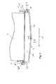
- a first embodiment of the filter cover 3 is shown.
- the filter cover 3 has a bottom wall 4, two longitudinal side walls 5 and two wide side walls 6, so that forms a trough 7 for collecting water on the filter cover 3 made of plastic.
- the air filter 2 (not in Fig. 1 shown) rests on ribs 11.
- the ribs 11 are formed perpendicular to a direction of movement of the air through the air filter 2 and serve to prevent flow around the air filter 2 and form a support for the air filter 2.
- a discharge nozzle 19 is formed and through the discharge nozzle 19 as Device 8 for discharging water from the tub 7, the derived in the tub 7 water can be derived.
- a hose not shown, to be connected to the discharge nozzle 19.
- a spring 10 of a tongue and groove joint 9 is formed.
- a correspondingly complementary groove for the introduction of the spring 10 on the filter cover 3 in the groove on the housing 1 is provided on the housing 1, in the upper end of the two broad side walls 6 respectively an A-side 12 as a stop side 12 of the filter cover 3 is present and on the two Lijnsdorfwandept 5 each have an F-side 13 as a guide page 13 available.
- the spring 10 and the tongue and groove connection 9 on the two A-sides 12 form a stop during the movement of the filter cover for connection and release with the housing 1, ie the tongue and groove connection 9 on the two broad side walls. 6 or the two A-sides 12 represent a stop tongue and groove connection 9.
- the springs 10 and tongue and groove connections 9 on the two Leksdorfwandept 5 and on the F-sides 13 form a guide page 13 and a guide tongue and groove connection 9.
- a horizontal movement of the filter cover 3 for connection to the housing 1 or for releasing the connection to the housing 1 serve the tongue and groove joints 9 at the two F-sides 13 as a guide rail for guiding the filter cover 3.
- the substantially horizontal direction of movement 17 of the filter cover 3 for connection and solution with the housing 1 is in Fig. 1 shown as an arrow.
- a longitudinal axis 14 of the F-side 13 and the tongue and groove connection 9 and the spring 10 on the F-sides 13 is substantially parallel to the direction of movement 17. Die evolve Lfitsachse 15 der Nut-Feder-Veritati 9 relating the spring 10 on the two A-sides 12 is perpendicular to the direction of movement 17, since the tongue and groove connection 9 forms a stop on the two A-sides 12.
- the filter cover 3 For connecting the filter cover 3 with the housing 1, z.
- the filter 10 are as long as to be inserted into the grooves on the housing 1 until the springs 10 at the A-sides 12 and the two broad side walls 6 form a stop, ie the springs 10 in accordance complementary grooves formed on the housing 1 are completely inserted.
- a second embodiment of the spring cover 3 is shown, In the following, only the differences from the first embodiment according to substantially Fig. 1 described.
- the air 26 conducted through the air cleaner 2 is moved in a flow direction from right to left as shown in FIG Fig. 3 parallel to the drawing plane of Fig. 3 passed through the air filter 2.
- the guided to the air filter 2 air 26 is passed through an air duct only partially shown to the air filter 2.
- the filter cover 3 has a discharge channel 18, in which the water accumulating in the air channel can be introduced into the trough 7 of the filter cover 3.
- a discharge opening 20 formed in the filter cover 3 serves to allow the water collecting in the trough 7 to be discharged through the discharge opening 20 and fed to a condensate discharge at the refrigerant evaporator.
- the discharge of this water can either be done by means of a separate hose to the condensate drain or the derivative or leadership of the water from the filter cover to the condensate is integrated into the housing 1 of the automotive air conditioning, especially if the lowest point of the tub is sufficiently high, that a gradient to the condensate drainage of the refrigerant evaporator to a sufficient extent, for. B. with a gradient between 15 ° and 18 ° exists.
- the bottom wall 4 of the filter cover 3 also has a gradient, for example in the form of a roof profile with an inclination in the range of 2 ° to 3 °, so that the water collecting in the trough 7 can be completely discharged through the discharge opening 20.
- Drip noses 16 serve that the water, in particular above the housing 1 at the tongue and groove connection 9, does not reach the tongue and groove connection 9.
- the filter cover 3 in another embodiment, not shown, an intermediate wall and the discharge channel 18 opens into a channel between the intermediate wall and the bottom wall 4.
- the water collecting at the air filter 2 collects above the intermediate wall.
- two separate derivatives for the water collecting in the discharge channel 18 and the water collecting at the air filter 2 are available.
- the channel between the intermediate wall and the bottom wall preferably opens into a car dunking 21st
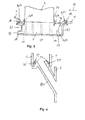
- Fig. 4 the car docking nozzle 21 is shown.
- the Autodockingstutzen 21 is formed for example in one piece with the filter cover 3.
- this has a docking end portion 22 which is formed parallel to the direction of movement 17 of the filter cover 3.
- a counter-opening 23 is provided on the housing 1.
- a seal 25 is partially arranged.
- the seal 25 may also be injected as a soft component (not shown).
- the tongue and groove joints 9 are generally not waterproof and are only for mechanical, positive fastening of the filter cover 3 to the housing 1.
- the tongue and groove connections 9 are thus formed either above the maximum possible water level of the water in the tub 7 or the filter cover 3 has a barrier wall 29 ( Fig. 2 ), so that no water to the in Fig. 2 shown right tongue and groove connection 9 passes. Notwithstanding this, the tongue and groove connections 9 may be formed waterproof, z. B. in 2-component technology in hard-soft design. Here, the soft component takes over the additional sealing effect (not shown).
- the filter cover 3 can be detachably mechanically connected to the housing 1 in a detachable manner with a substantially horizontal movement on the housing 1.
Abstract
Description
Die vorliegende Erfindung betrifft eine Kraftfahrzeugklimaanlage gemäß dem Oberbegriff des Anspruches 1.The present invention relates to an automotive air conditioning system according to the preamble of
Kraftfahrzeugklimaanlagen werden in Kraftfahrzeugen eingesetzt, um die einem Innenraum des Kraftfahrzeuges zuzuführende Luft zu erwärmen und/oder zu kühlen. Hierzu weist die Kraftfahrzeugklimaanlage ein Gehäuse auf und innerhalb des Gehäuses sind aus dem Gehäuse aus Kunststoff Luftkanäle begrenzt. Mittels eines Gebläses wird die Luft aus der Umgebung oder dem Innenraum des Kraftfahrzeuges angesaugt und mit einem Kältemittelverdampfer optional gekühlt und mit einer Heizeinrichtung optional erwärmt. Ein Luftfilter dient zum Filtern der Luft. Beim Ansaugen der Luft aus der Umgebung kann diese auch mit Wasser, z. B. in Form von Wassertropfen oder von Schnee, versetzt sein. Hierzu ist die Kraftfahrzeugklimaanlage mit einem Wasserabscheider versehen, damit möglichst wenig Wasser beim Ansaugen mit dem Gebläse zu dem Luftfilter gelangt. In zunehmendem Ausmaße aufgrund konstruktiver Anforderungen, insbesondere aufgrund eines immer geringer werdenden zur Verfügung stehenden Bauraumes, erfolgt eine Wasserabscheidung mit einer geringeren Effektivität. Dadurch gelangt in größerem Ausmaß Wasser zu dem Luftfilter, welches sich an diesem ansammelt. Aus diesem Grund ist es erforderlich, das sich am Luftfilter ansammelnde Wasser in einer Wanne an einem Filterdeckel zu sammeln und abzuleiten. Mittels des lösbar mit dem Gehäuse der Kraftfahrzeugklimaanlage verbundenen Filterdeckels kann auch der Luftfilter bei einem Entfernen des Filterdeckels von dem Gehäuse für Wartungszwecke ausgetauscht werden.Automotive air conditioning systems are used in motor vehicles to heat and / or to cool the air to be supplied to an interior of the motor vehicle. For this purpose, the motor vehicle air conditioner on a housing and within the housing are limited from the plastic housing air channels. By means of a blower, the air is sucked from the environment or the interior of the motor vehicle and optionally cooled with a refrigerant evaporator and optionally heated with a heater. An air filter is used to filter the air. When sucking in the air from the environment this can also be with water, eg. B. in the form of water droplets or snow, be offset. For this purpose, the motor vehicle air conditioning system is provided with a water separator, so that as little water as possible when sucking with the blower reaches the air filter. To an increasing extent due to design requirements, in particular due to an ever decreasing available space, a water separation takes place with a lower efficiency. As a result, more water reaches the air filter, which accumulates at this. For this reason, it is necessary that accumulating on the air filter Collect and drain water in a tub on a filter cover. By means of the filter cover detachably connected to the housing of the motor vehicle air conditioning system, the air filter can also be exchanged for maintenance purposes when the filter cover is removed from the housing.
Die DIE
Aus der
Die Aufgabe der vorliegenden Erfindung besteht deshalb darin, eine Kraftfahrzeugklimaanlage zur Verfügung zu stellen, bei der eine konstruktiv einfache Verbindung eines Filterdeckels mit einem Gehäuse der Kraftfahrzeugklimaanlage bei guter Handhabung möglich ist.The object of the present invention is therefore to provide an automotive air conditioning system, in which a structurally simple connection of a filter cover with a housing of the motor vehicle air conditioning system is possible with good handling.
Diese Aufgabe wird gelöst mit einer Kraftfahrzeugkimaanlage, umfassend ein Gehäuse, wenigstens einen Luftkanal zum Durchleiten von Luft, ein Gebläse, einen Luftfilter, einen Filterdeckel mit einer Wanne zum Sammeln von Wasser an dem Luftfilter und vorzugsweise einer Einrichtung zum Ableiten des Wassers aus der Wanne, Nut-Feder-Verbindung zum lösbaren Verbinden des Filterdeckels mit dem Gehäuse, wobei der Filterdeckel aufgrund der Geometrie der Nut-Feder-Verbindung mittels einer, insbesondere ausschließlich, im Wesentlichen horizontalen Bewegung des Filterdeckels mit dem verbindbar und lösbar ist. In vorteilhafter Weise kann somit mit einer im Wesentlichen horizontalen Bewegung, d. h. einer horizontalen Translationsbewegung, der Filterdeckel mit dem der Kraftfahrzeuge verbunden und auch wieder gelöst werden. Eine im Wesentlichen horizontale Bewegung bzw. Translationsbewegung ist dabei eine Bewegung bzw. Translationsbewegung mit einer Abweichung von weniger als 30°, 20°, 10° oder 5° zu einer horizontalen Achse oder Ebene. Bei der Wartung der Kraftfahrzeugktimaanlage ist es somit möglich, den Filterdeckel besonders einfach mittels der Nut-Feder-Verbindung mit dem Gehäuse zu verbinden und Verbindung auch wieder zu lösen.This object is achieved with a motor vehicle air conditioning system comprising a housing, at least one air duct for passing air, a fan, an air filter, a filter cover with a trough for collecting water at the air filter and preferably a device for discharging the water from the tub, tongue and groove connection for releasably connecting the filter cover to the housing, wherein the filter cover due to the geometry of the tongue and groove connection by means of a, in particular exclusively, substantially horizontal movement of the filter cover with the connectable and detachable , In an advantageous manner, the filter cover can thus be connected to the motor vehicle and also released again with a substantially horizontal movement, ie a horizontal translational movement. A substantially horizontal movement or translational movement is a movement or translational movement with a deviation of less than 30 °, 20 °, 10 ° or 5 ° to a horizontal axis or plane. When servicing the motor vehicle air conditioning system, it is thus possible to connect the filter cover particularly easily by means of the tongue and groove connection with the housing and also to loosen the connection.
In einer ergänzenden Ausgestaltung ist der Filterdeckel mit einer Schwenkbewegung mit dem Gehäuse verbindbar und lösbar. Hierzu weist z. B. der Filterdeckel an einer A-Seite eine Feder für eine Nut-Feder-Verbindung auf und an einer gegenüberliegenden weiteren A-Seite eine Rast- oder Clipsverbindung auf. Beim Verbinden des Filterdeckels mit dem Gehäuse wird zuerst die Feder in die Nut der Nut-Feder-Verbindung an der A-Seite eingeschoben, anschließend der Filterdeckel verschwenkt, so dass an den anderen, senkrecht zu der A-Seite ausgerichteten Seiten eine Feder in die Nut der Nut-Feder-Verbindung an den anderen Seiten eingeschoben wird und anschließend wird mit der Rast- oder Clipsverbindung an der weiteren A-Seite der Filterdeckel mit dem Gehäuse verbunden.In a supplementary embodiment of the filter cover with a pivoting movement with the housing is connected and detachable. For this purpose, z. B. the filter cover on an A-side a spring for a tongue and groove connection and on an opposite other A-side a locking or clip connection. When connecting the filter cover with the housing, the spring is first inserted into the groove of the tongue and groove joint on the A-side, then the filter cover pivoted so that at the other, aligned perpendicular to the A-side sides of a spring in the Groove of the tongue and groove joint is inserted at the other sides and then is connected to the detent or clip connection on the other A side of the filter cover to the housing.
Zweckmäßig umfaßt die Kraftfahrzeugklimaanlage eine Fixierungseinrichtung, z. B. ein Bajonettverschluss, Rastverbindung oder eine Schraubverbindung, mittels der der Filterdeckel mit dem Gehäuse lösbar verbindbar ist. Nach dem horizontalen Einschieben des Filterdeckels bis zu einem Anschlag kann somit in dieser Stellung des Filterdeckels mittels der Fixierungseinrichtung der Filterdeckel lösbar an dem Gehäuse der Kraftfahrzeugklimaanlage fixiert werden.Suitably, the motor vehicle air conditioner comprises a fixing device, for. As a bayonet lock, latching connection or a screw, by means of the filter cover to the housing is detachably connectable. After the horizontal insertion of the filter cover up to a stop can thus in this position of the filter cover by means of the fixing device the filter cover be releasably fixed to the housing of the motor vehicle air conditioner.
Insbesondere ist die Nut-Feder-Verbindung an einer A-Seite, vorzugsweise an zwei gegenüberliegenden A-Seiten, des Filterdeckels im Wesentliche horizontal ausgerichtet, so dass die im Wesentlichen horizontal ausgerichtete Nut-Feder-Verbindung als Anschlag bei der im Wesentlichen horizontalen Bewegung des Filterdeckels zum Verbinden mit dem Gehäuse dient. Im Wesentlichen horizontal ausgerichtete bedeutet dabei, dass die Nut-Feder-Verbindung mit einer Abweichung von weniger als 30°, 20°, 10° oder 5° zu einer horizontalen Ebene oder Achse ausgerichtet ist. Die A-Seite bzw. die A-Nut-Feder-Verbindung dient somit als Anschlag beim Einschieben des Filterdeckels an dem Gehäuse.In particular, the tongue and groove connection on an A-side, preferably on two opposite A sides of the filter cover substantially horizontally aligned, so that the substantially horizontally oriented tongue and groove connection as a stop in the substantially horizontal movement of the Filter cover for connecting to the housing is used. Essentially horizontally oriented means that the tongue and groove connection is aligned with a deviation of less than 30 °, 20 °, 10 ° or 5 ° to a horizontal plane or axis. The A-side or the A-tongue and groove connection thus serves as a stop when inserting the filter cover to the housing.
In einer weiteren Ausgestaltung dient die Nut-Feder-Verbindung an einer F-Seite, vorzugsweise an zwei gegenüberliegenden F-Seiten, als Führungsschiene zur Führung des Filterdeckels bei der Bewegung des Filterdeckels zum Verbinden und Lösen mit dem Gehäuse. Die Nut-Feder-Verbindung an der F-Seite bzw. die F-Nut-Feder-Verbindung dient somit zur Führung des Filterdeckels bei der Bewegung des Filterdeckels zum Verbinden und Lösen mit dem Gehäuse.In a further embodiment, the tongue and groove connection on an F side, preferably on two opposite F sides, serves as a guide rail for guiding the filter cover during the movement of the filter cover for connecting and disconnecting with the housing. The tongue and groove connection on the F side and the F-tongue and groove connection thus serves to guide the filter cover during the movement of the filter cover for connecting and disconnecting with the housing.
In einer ergänzenden Ausführungsform ist die Nut-Feder-Verbindung an der einen F-Seite, vorzugsweise an zwei F-Seiten, im Wesentlichen vertikal ausgerichtet. Im Wesentlichen vertikal ausgerichtet bedeutet dabei, dass die Nut-Feder-Verbindung mit einer Abweichung von weniger als 30°, 20°, 10° oder 5° zu einer vertikalen Ebene oder Gerade ausgerichtet ist.In an additional embodiment, the tongue and groove joint is oriented substantially vertically on one F-side, preferably on two F-sides. Aligned substantially vertically means that the tongue and groove connection is aligned with a deviation of less than 30 °, 20 °, 10 ° or 5 ° to a vertical plane or straight line.
Vorzugsweise ist eine Längsachse der Nut und/oder der Feder der Nut-Feder-Verbindung an der einen F-Seite, vorzugsweise an zwei F-Seiten, im Wesentlichen parallel zu einer Bewegungsrichtung der horizontalen Bewegung zum Verbinden und Lösen des Filterdeckels mit dem Gehäuse ausgerichtet.Preferably, a longitudinal axis of the groove and / or the spring of the tongue and groove joint on the one F side, preferably on two F sides, is substantially parallel to a direction of movement of the horizontal movement aligned with the housing for connecting and disconnecting the filter cover.
In einer Variante liegt der Luftfilter auf wenigstens einer Rippe auf und die Rippe ist an dem Filterdeckel ausgebildet und vorzugsweise ist die wenigstens eine Rippe im Wesentlichen senkrecht zu einer Strömungsrichtung der durch den Luftfilter geleiteten Luft ausgerichtet, so dass die wenigstens eine Rippe als Luftdichtung und/oder Labyrinthdichtung zur Vermeidung einer Umströmung des Luftfilters mit Luft fungiert, Die wenigstens eine Rippe ist vorzugsweise einteilig an dem Filterdeckel aus Kunststoff ausgebildet, d. h. beim Spritzgießen des Filterdeckels aus Kunststoff kann die wenigstens eine Rippe, vorzugsweise mehrere Rippen, einfach beim Spritzgießen des Filterdeckels kostengünstig hergestellt werden. Die wenigstens eine Rippe verhindert oder vermeidet eine Umströmung des Luftfilters, so dass die gesamte in den Innenraum des Kraftfahrzeuges geleitete Luft durch den Luftfilters geleitet ist. Vorzugsweise ist dabei die Rippe vollständig in einer Richtung senkrecht zu einer Strömungsrichtung der Luft durch den Luftfilter ausgebildet, so dass eine Umströmung der wenigstens einen Rippe nicht möglich ist und der Luftfilter auf der wenigstens einen Rippe vollständig aufliegt. Vorzugsweise ist die Breite der wenigstens einen Rippe zwischen dem 0,1- und 0,9-Fachen, insbesondere zwischen dem 0,7- und 0,9-Fachen, der Breite oder Länge des Luftfilters,In one variant, the air filter rests on at least one rib and the rib is formed on the filter cover and preferably the at least one rib is oriented substantially perpendicular to a flow direction of the air guided through the air filter, so that the at least one rib serves as an air seal and / or labyrinth seal with air to prevent a flow around the air filter, the at least one rib is preferably formed integrally on the filter cover made of plastic, d. H. during injection molding of the filter cover made of plastic, the at least one rib, preferably a plurality of ribs, can be produced inexpensively during injection molding of the filter cover. The at least one rib prevents or avoids a flow around the air filter, so that the entire guided into the interior of the motor vehicle air is passed through the air filter. Preferably, the rib is completely formed in a direction perpendicular to a flow direction of the air through the air filter, so that a flow around the at least one rib is not possible and the air filter rests completely on the at least one rib. Preferably, the width of the at least one rib is between 0.1 and 0.9 times, in particular between 0.7 and 0.9 times, the width or length of the air filter,
Zweckmäßig weist die Kraftfahrzeugklimaanlage einen Ableitungskanal zur Ableitung von Wasser in einem zu dem Luftfilter führenden Luftkanal auf. Zu dem Luftfilter wird die Luft durch einen Luftkanal geführt. In diesem Luftkanal, welcher zu dem Luftfilter führt, kann sich Wasser ansammeln, welches durch feuchte Luft als Wassertropfen mitgeführt oder aus Schneepartikeln entstehen kann. Damit Wasser nicht in den Luftfilter gelangt, wird das Wasser mit Hilfe eines Ableitungskanales abgeleitet. Der Ableitungskanal ist vorzugsweise in Strömungsrichtung der durch den Luftfilter geleiteten Luft vor dem Luftfilter ausgebildet. Beispielsweise sind hierzu am Gehäuse der Kraftfahrzeugklimaanlage oder auch am Filterdeckel, je nach der Ausbildung des Ableitungskanales, Ableitungsöffnungen ausgebildet, in welche das Wasser einströmen kann, Mittels einer Wasserleiste im Bereich des Luftfilters, insbesondere ummittelbar an dem Luftfilter als Barriere wird verhindert, dass das Wasser in dem Luftkanal, welcher zu dem Luftfilter führt, an den Luftfilter gelangen kann und dadurch vollständig in die Ableitungsöffnungen, welche zu dem Ableitungskanal führen, geleitet wird.The motor vehicle air conditioning system expediently has a discharge channel for discharging water in an air duct leading to the air filter. To the air filter, the air is passed through an air duct. In this air duct, which leads to the air filter, water can accumulate, which can be carried by moist air as water droplets or formed from snow particles. So that water does not get into the air filter, the water is discharged with the help of a discharge channel. The discharge channel is preferably formed in the flow direction of the guided through the air filter air in front of the air filter. For example, this is the case of the Automotive air conditioning or on the filter cover, depending on the formation of the discharge channel, discharge openings formed in which the water can flow, by means of a water bar in the region of the air filter, in particular ummittelbar to the air filter as a barrier prevents the water in the air duct, which to the air filter leads, can get to the air filter and thereby completely in the discharge openings, which lead to the discharge channel, is passed.
In einer weiteren Ausführungsform ist der Ableitungskanal an dem Gehäuse der Kraftfahrzeugklimaanlage oder an dem Filterdeckel ausgebildet und vorzugsweise mündet der Ableitungskanal bei einer Ausbildung an dem Filterdeckel in die Einrichtung zum Ableiten des Wassers aus der Wanne.In a further embodiment, the discharge channel is formed on the housing of the motor vehicle air conditioner or on the filter cover and preferably the discharge channel opens in a design on the filter cover in the device for discharging the water from the tub.
Insbesondere umfasst der Filterdeckel einen Autodockingstutzen zum Ableiten des Wassers aus der Wanne und der Autodockingstutzen ist an einem Dockingendabschnitt im Wesentlichen parallel zu der Bewegungsrichtung des Filterdeckels zum Verbinden und Lösen mit dem Gehäuse ausgerichtet, so dass durch eine komplementär ausgebildeten Gegenöffnung an dem Gehäuse beim Bewegen des Filterdeckels selbständig eine fluidleitende Verbindung von dem Autodockingstutzen zu der Gegenöffnung an dem Gehäuse herstellbar und aufhebbar ist.In particular, the filter cover comprises a car docks for draining the water from the tub and the car docks is aligned at a docking end portion substantially parallel to the direction of movement of the filter cover for connection and detachment with the housing, so that by a complementarily formed counter-opening on the housing during movement of the Filter lid independently a fluid-conducting connection of the autodocking nozzle to the counter-opening on the housing produced and can be canceled.
In einer weiteren Ausgestaltung ist die Breite der Öffnung an dem Gehäuse für den Luftfilter kleiner, vorzugsweise wenigstens um das 0,9-, 0,8- oder 0,7-Fache kleiner, als die Breite des Filterdeckels. An dem Gehäuse sind Stege mit Tropfnasen ausgebildet, welche in einem Abstand zu einer Nut-Feder-Verbindung ausgebildet sind, so die der Öffnung an dem Gehäuse kleiner ist als die Breite des Filterdeckels,In a further embodiment, the width of the opening on the housing for the air filter is smaller, preferably at least 0.9, 0.8 or 0.7 times smaller than the width of the filter cover. On the housing webs are formed with drip noses, which are formed at a distance from a tongue and groove connection, so that the opening on the housing is smaller than the width of the filter cover,
Vorzugsweise ist am Rand des Filterdeckels und/oder am Gehäuse, insbesondere im Bereich der Nut-Federverbindung, ein Kanal zum Leiten des Wassers von dem Ableitungskanal zu der Ablauföffnung ausgebildet.Preferably, at the edge of the filter cover and / or on the housing, in particular in the region of the tongue and groove connection, a channel for guiding the water from the discharge channel to the drain opening is formed.
In einer weiteren Ausgestaltung weist der Filterdeckel keine Ableitung von sich an dem Luftfilter sammelnden Wasser auf. Das sich am Luftfilter sammelnde Wasser muss somit verdunsten und von der durch den Luftfilter geleiteten Luft mitgenommen.In a further embodiment, the filter cover on no derivative of collecting at the air filter water. The water collecting at the air filter must therefore evaporate and be carried along by the air routed through the air filter.
In einer ergänzenden Ausführungsform ist die Ableitungsöffnung an der Bodenwandung des Filterdeckels, insbesondere im Wesentlichen mittig an der Bodenwandung, ausgebildet. Die Rippen sind dabei vorzugsweise wenigstens teilweise, insbesondere vollständig, nicht parallel, sondern in einem spitzen Winkel zueinander ausgerichtet, so dass das zwischen den Rippen auf der Bodenwandung zu der Ableitungsöffnung abfließende Wasser zu der Ableitungsöffnung ableitbar ist. Die Rippen sind vorzugsweise in wenigstens teilweise, insbesondere vollständig, im Wesentlichen in Fließrichtung des Wassers zu der Ableitungsöffnung Vorzugsweise weist die Bodenwandung ein Gefälle zu der Ableitungsöffnung auf.In a supplementary embodiment, the discharge opening is formed on the bottom wall of the filter cover, in particular substantially in the center of the bottom wall. The ribs are preferably at least partially, in particular completely, not parallel, but aligned at an acute angle to each other, so that the effluent between the ribs on the bottom wall to the discharge opening water to the discharge opening can be derived. The ribs are preferably in at least partially, in particular completely, substantially in the direction of flow of the water to the discharge opening. Preferably, the bottom wall has a slope to the discharge opening.
In einer weiteren Ausgestaltung umfasst die Kraftfahrzeugklimaanlage ein Gebläse und/oder eine Heizeinrichtung und/oder einen Kältemittelverdampfer und/oder einen Kondenswasserablauf zum Ableiten von Kondenswasser an dem Kältemittelverdampfer und/oder die Einrichtung zum Ableiten des Wassers aus der Wanne mündet in den Kondenswasserablauf an dem Kältemittelverdampfer.In a further refinement, the motor vehicle air-conditioning system comprises a fan and / or a heating device and / or a refrigerant evaporator and / or a condensate drain for draining condensation water on the refrigerant evaporator and / or the device for draining the water from the trough empties into the condensate drain on the refrigerant evaporator ,
Zweckmäßig besteht das Gehäuse der Kraftfahrzeugklimaanlage und/oder der Filterdeckel wenigstens teilweise, insbesondere vollständig, aus Kunststoff.Suitably, the housing of the motor vehicle air conditioner and / or the filter cover at least partially, in particular completely, made of plastic.
Im Nachfolgenden werden Ausführungsbeispiele der Erfindung unter Bezugnahme auf die beigefügten Zeichnungen näher beschrieben. Es zeigt:
- Fig.
- 1 eine perspektivische Ansicht eines Filterdeckels in einem ersten Ausführungsbeispiel,
- Fig. 2
- einen Schnitt parallel zu einer Bewegungsrichtung des Filterdeckels in einem zweiten Ausführungsbeispiel
- Fig. 3
- einen Schnitt senkrecht zu einer Bewegungsrichtung des Filterdeckels in dem zweiten Ausführungsbeispiel und
- Fig. 4
- einen Schnitt eines Autodockingstutzens und einer Gegenöffnung an dem Gehäuse.
- FIG.
- 1 is a perspective view of a filter cover in a first Embodiment,
- Fig. 2
- a section parallel to a direction of movement of the filter cover in a second embodiment
- Fig. 3
- a section perpendicular to a direction of movement of the filter cover in the second embodiment and
- Fig. 4
- a section of a car docking nozzle and a counter-opening on the housing.
Eine nicht dargestellte Kraftfahrzeugklimaanlage für ein Kraftfahrzeug weist ein Gehäuse 1 aus Kunststoff auf. Innerhalb des Gehäuses 1 ist ein Gebläse, ein Luftfilter 2, ein Kältemittelverdampfer zum Kühlen der Luft und eine Heizeinrichtung zum Erwärmen der Luft angeordnet. Das Gehäuse 1 begrenzt dabei Luftkanäle zum Durchleiten der Luft. Mittels einer nicht dargestellten Umluftklappe wird gesteuert, ob von dem Gebläse Luft aus der Umgebung des Kraftfahrzeuges oder aus dem Innenraum des Kraftfahrzeuges angesaugt wird. Ein Wasserabscheider dient dazu, die angesaugte Luft, insbesondere die aus der Umgebung des Kraftfahrzeuges angesaugte Luft, in Luft und Wasser zu trennen. Trotz der Wasserabscheidung kann es jedoch vorkommen, auch zu dem Luftfilter 2 Wasser gelangt. Aus diesem Grund ist es erforderlich, dass das an dem Luftfilter 2 angesammelte Wasser aufgefangen und abgeleitet wird.An unillustrated motor vehicle air conditioning system for a motor vehicle has a
Unterhalb des Luftfilters 2 ist ein Filterdeckel 3 mit dem Gehäuse 1 der Kraftfahrzeugklimaanlage lösbar verbunden. Der Filterdeckel 3 kann von dem Gehäuse 1 entfernt werden, um bei einer Wartung der Kraftfahrzeugklimaanlage den Luftfilter 2 auszuwechseln. Hierzu ist der Filterdeckel 3 vertikal unterhalb des Luftfilters 2 mit dem Gehäuse 1 verbunden.Below the
In
Zur Verbindung des Filterdeckels 3 mit dem Gehäuse 1 ist hierzu am Gehäuse 1 eine entsprechend komplementär ausgebildete Nut (nicht dargestellt) zur Einführung der Feder 10 an dem Filterdeckel 3 in die Nut an dem Gehäuse 1 vorhanden, Im oberen Endbereich der beiden Breitseitenwandungen 6 ist jeweils eine A-Seite 12 als Anschlagseite 12 des Filterdeckels 3 vorhanden und an den beiden Längsseitenwandungen 5 jeweils eine F-Seite 13 als Führungsseite 13 vorhanden. Die Feder 10 bzw. die Nut-Feder-Verbindung 9 an den beiden A-Seiten 12 bilden dabei einen Anschlag bei der Bewegung des Filterdeckels zur Verbindung und Lösung mit dem Gehäuse 1, d. h. die Nut-Feder-Verbindung 9 an den beiden Breitseitenwandungen 6 bzw. den beiden A-Seiten 12 stellen eine Anschlag-Nut-Feder-Verbindung 9 dar. Die Federn 10 bzw. Nut-Feder-Verbindungen 9 an den beiden Längsseitenwandungen 5 bzw. an den F-Seiten 13 bilden eine Führungsseite 13 bzw. eine Führungs-Nut-Feder-Verbindung 9. Bei einer horizontalen Bewegung des Filterdeckels 3 zur Verbindung mit dem Gehäuse 1 oder zum Lösen der Verbindung mit dem Gehäuse 1 dienen die Nut-Feder-Verbindungen 9 an den beiden F-Seiten 13 als Führungsschiene zur Führung des Filterdeckels 3. Die im Wesentlichen horizontale Bewegungsrichtung 17 des Filterdeckels 3 zur Verbindung und Lösung mit dem Gehäuse 1 ist in
Zum Verbinden des Filterdeckels 3 mit dem Gehäuse 1, z. B. bei einer Wartung der Kraftfahrzeugklimaanlage und einem erforderlichen Wechsel des Luftfilters 2, sind zunächst die beiden Federn 10 an den F-Seiten 13 bzw. den beiden Längsseitenwandungen 5 in entsprechend komplementär ausgebildete Nuten an dem Gehäuse 1 einzuführen und dadurch erfolgt eine Führung der Bewegung des Filterdeckels 3 relativ zu dem Gehäuse 1. Die Filter 10 sind dabei solange in die Nuten an dem Gehäuse 1 einzuschieben, bis die Federn 10 an den A-Seiten 12 bzw. den beiden Breitseitenwandungen 6 einen Anschlag bilden, d. h. die Federn 10 in entsprechend komplementär ausgebildeten Nuten an dem Gehäuse 1 vollständig eingeführt sind. In dieser Stellung des Filterdeckels 3 an dem Gehäuse 1 ist somit der Filterdeckel 3 mit dem Gehäuse 1 formschlüssig aufgrund der Nut-Feder-Verbindungen 9 verbunden und damit der Filterdeckel 3 sich nicht von dem Gehäuse 1 löst, kann mittels eines nicht dargestellten Bajonettverschlusses als Fixierungseinrichtung eine Bewegung des Filterdeckels 3 relativ zu dem Gehäuse 1 verhindert werden. Zum Lösen bzw. Entfernen des Filterdeckels 3 ist somit in umgekehrter Weise zunächst der Bajonettverschluss zu lösen und anschließend der Filterdeckel 3 in einer horizontalen Bewegungsrichtung 17 von dem Gehäuse 1 zu entfernen, d. h. die Federn 10 an den F-Seiten 13 werden aus den entsprechenden Nuten an dem Gehäuse 1 herausgeschoben.For connecting the
In
Abweichend zu dem in
In
Die Nut-Feder-Verbindungen 9 sind im Allgemeinen nicht wasserdicht und dienen lediglich zur mechanischen, formschlüssigen Befestigung des Filterdeckels 3 an dem Gehäuse 1. Die Nut-Feder-Verbindungen 9 sind somit entweder oberhalb des maximal möglichen Wasserspiegels des Wassers in der Wanne 7 ausgebildet oder der Filterdeckel 3 weist eine Barrierewandung 29 auf (
Insgesamt betrachtet sind mit der erfindungsgemäßen Kraftfahrzeugklimaanlage wesentliche Vorteile verbunden. Der Filterdeckel 3 kann an dem Gehäuse 1 besonders einfach mit einer im Wesentlichen horizontalen Bewegung an dem Gehäuse 1 lösbar mechanisch verbunden werden. Durch eine effektive Wasserableitung des sich an dem Luftfilter 2 sammelnden Wassers sowie einen Ableitungskanal 18, in welche Ableitungsöffnungen 28 münden, kann das sich am Luftfilter 2 sammelnde Wasser besonders gut abgeleitet werden.Overall, significant advantages are associated with the automotive air conditioning system according to the invention. The
- 11
- Gehäusecasing
- 22
- Luftfilterair filter
- 33
- Filterdeckelfilter cover
- 44
- Bodenwandungbottom wall
- 55
- Längsseitenwandunglongitudinal side
- 66
- BreitseitenwandungBreitseitenwandung
- 77
- Wannetub
- 88th
- Einrichtung zum Ableiten von Wasser aus der WanneDevice for draining water from the tub
- 99
- Nut-Feder-VerbindungTongue and groove
- 1010
- Federfeather
- 1111
- Ripperib
- 1212
- A-SeiteA side
- 1313
- F-SeiteF side
- 1414
- Längsachse der F-SeiteLongitudinal axis of the F side
- 1515
- Längsachse der A-SeiteLongitudinal axis of the A-side
- 1616
- Tropfnaseclapboard
- 1717
- Bewegungsrichtungmovement direction
- 1818
- AbleitungskanalWaterway
- 1919
- Ableitungsstutzenderivation neck
- 2020
- Ableitungsöffnung in FilterdeckelDischarge opening in filter cover
- 2121
- AutodockingstutzenCar Docking socket
- 2222
- DockingendabschnittDockingendabschnitt
- 2323
- Gegenöffnungagainst opening
- 2424
- Ringnut in DockingabschnittRing groove in docking section
- 2525
- Dichtung in RingnutSeal in ring groove
- 2626
- Luftair
- 2727
- Wasserleistewater border
- 2828
- Ableitungsöffnungdischarge port
- 2929
- BarrierewandungBarrierewandung
Claims (10)
der Filterdeckel (3) aufgrund der Geometrie der Nut-Feder-Verbindung (9) mittels einer, insbesondere ausschließlich, im Wesentlichen horizontalen Bewegung des Filterdeckels (3) mit dem Gehäuse (1) verbindbar und lösbar ist.Automotive air conditioning system comprising
the filter cover (3) due to the geometry of the tongue and groove connection (9) by means of a, in particular exclusively, substantially horizontal movement of the filter cover (3) with the housing (1) is connectable and detachable.
Applications Claiming Priority (1)
| Application Number | Priority Date | Filing Date | Title |
|---|---|---|---|
| DE102011007754A DE102011007754A1 (en) | 2011-04-20 | 2011-04-20 | Automotive air conditioning system |
Publications (3)
| Publication Number | Publication Date |
|---|---|
| EP2514617A2 true EP2514617A2 (en) | 2012-10-24 |
| EP2514617A3 EP2514617A3 (en) | 2013-01-02 |
| EP2514617B1 EP2514617B1 (en) | 2017-06-14 |
Family
ID=45992108
Family Applications (1)
| Application Number | Title | Priority Date | Filing Date |
|---|---|---|---|
| EP12164980.0A Not-in-force EP2514617B1 (en) | 2011-04-20 | 2012-04-20 | Motor vehicle air conditioning |
Country Status (2)
| Country | Link |
|---|---|
| EP (1) | EP2514617B1 (en) |
| DE (1) | DE102011007754A1 (en) |
Cited By (3)
| Publication number | Priority date | Publication date | Assignee | Title |
|---|---|---|---|---|
| CN106042822A (en) * | 2015-04-06 | 2016-10-26 | 法雷奥日本株式会社 | Vehicle air-conditioning apparatus |
| CN108569105A (en) * | 2017-03-08 | 2018-09-25 | 翰昂汽车零部件有限公司 | Strainer cover and air handling system for the vehicle with the strainer cover |
| FR3093164A1 (en) * | 2019-02-25 | 2020-08-28 | Valeo Systemes Thermiques | Housing for heating, air conditioning and / or ventilation device for motor vehicle |
Families Citing this family (4)
| Publication number | Priority date | Publication date | Assignee | Title |
|---|---|---|---|---|
| DE102014112535B4 (en) | 2014-09-01 | 2021-07-01 | Denso Automotive Deutschland Gmbh | Motor vehicle air conditioning system with detachably connected filter cover |
| DE102015201154B4 (en) | 2015-01-23 | 2023-05-04 | Mahle International Gmbh | vehicle air conditioning |
| DE102015203138A1 (en) | 2015-02-20 | 2016-08-25 | Mahle International Gmbh | Air filter element and air filter |
| DE102016209628A1 (en) * | 2016-06-01 | 2017-12-07 | Mahle International Gmbh | Heating, ventilation or air conditioning |
Citations (2)
| Publication number | Priority date | Publication date | Assignee | Title |
|---|---|---|---|---|
| DE102008007915A1 (en) | 2008-02-06 | 2009-08-13 | Behr Gmbh & Co. Kg | Lid housing arrangement, in particular for a filter of a vehicle ventilation system |
| DE102009009065A1 (en) | 2009-02-16 | 2010-08-19 | Behr Gmbh & Co. Kg | Air conditioning for a motor vehicle |
Family Cites Families (6)
| Publication number | Priority date | Publication date | Assignee | Title |
|---|---|---|---|---|
| DE3223812A1 (en) * | 1982-06-25 | 1983-12-29 | International Harvester Company Mbh, 4040 Neuss | Air-conditioning system for motor vehicles |
| GB2364001B (en) * | 2000-06-29 | 2003-06-25 | Valeo Climate Control Ltd | Air filter |
| DE10334567A1 (en) * | 2003-07-28 | 2005-02-24 | Behr Gmbh & Co. Kg | A filter assembly |
| FR2865159B1 (en) * | 2004-01-21 | 2006-02-24 | Valeo Climatisation | DEVICE FOR SHUTTING OFF A VENTILATION, HEATING AND / OR AIR CONDITIONING FACILITATION FACILITATING ACCESS TO A FILTERING MEANS. |
| ATE439268T1 (en) * | 2004-09-29 | 2009-08-15 | Behr Gmbh & Co Kg | AIR DUCT HOUSING FOR MOTOR VEHICLES |
| DE502008002602D1 (en) * | 2007-11-26 | 2011-03-31 | Behr Gmbh & Co Kg | Air conditioning for a motor vehicle |
-
2011
- 2011-04-20 DE DE102011007754A patent/DE102011007754A1/en not_active Withdrawn
-
2012
- 2012-04-20 EP EP12164980.0A patent/EP2514617B1/en not_active Not-in-force
Patent Citations (2)
| Publication number | Priority date | Publication date | Assignee | Title |
|---|---|---|---|---|
| DE102008007915A1 (en) | 2008-02-06 | 2009-08-13 | Behr Gmbh & Co. Kg | Lid housing arrangement, in particular for a filter of a vehicle ventilation system |
| DE102009009065A1 (en) | 2009-02-16 | 2010-08-19 | Behr Gmbh & Co. Kg | Air conditioning for a motor vehicle |
Cited By (7)
| Publication number | Priority date | Publication date | Assignee | Title |
|---|---|---|---|---|
| CN106042822A (en) * | 2015-04-06 | 2016-10-26 | 法雷奥日本株式会社 | Vehicle air-conditioning apparatus |
| EP3078518A3 (en) * | 2015-04-06 | 2017-01-18 | Valeo Japan Co., Ltd. | Vehicle air-conditioning apparatus |
| CN106042822B (en) * | 2015-04-06 | 2018-09-11 | 法雷奥日本株式会社 | Air conditioner for vehicles |
| US10166843B2 (en) | 2015-04-06 | 2019-01-01 | Valeo Japan Co., Ltd. | Vehicle air-conditioning apparatus |
| CN108569105A (en) * | 2017-03-08 | 2018-09-25 | 翰昂汽车零部件有限公司 | Strainer cover and air handling system for the vehicle with the strainer cover |
| FR3093164A1 (en) * | 2019-02-25 | 2020-08-28 | Valeo Systemes Thermiques | Housing for heating, air conditioning and / or ventilation device for motor vehicle |
| WO2020174147A1 (en) * | 2019-02-25 | 2020-09-03 | Valeo Systemes Thermiques | Housing for a heating, air-conditioning and/or ventilation device for a motor vehicle |
Also Published As
| Publication number | Publication date |
|---|---|
| EP2514617A3 (en) | 2013-01-02 |
| DE102011007754A1 (en) | 2012-10-25 |
| EP2514617B1 (en) | 2017-06-14 |
Similar Documents
| Publication | Publication Date | Title |
|---|---|---|
| EP2514617B1 (en) | Motor vehicle air conditioning | |
| DE19811189C1 (en) | Automobile body with electrical auxiliaries separated from engine compartment | |
| DE102010062406B4 (en) | Air conditioner for a vehicle | |
| EP2062761B1 (en) | Air conditioning unit for a motor vehicle | |
| DE102017109986B4 (en) | Arrangement of several plinth ventilation boxes for assembly in a furniture plinth, a furniture plinth and a corresponding downdraft extractor device | |
| EP0200899B1 (en) | Apparatus for ventilating and air conditioning driver's areas, driver's cabs or the like | |
| WO2016207019A1 (en) | Condenser unit of a roof-mounted air conditioning system | |
| EP2218598B1 (en) | Vehicle air conditioning system | |
| DE102014112535B4 (en) | Motor vehicle air conditioning system with detachably connected filter cover | |
| DE102011011975A1 (en) | Air intake device of a vehicle interior ventilation system and vehicle interior ventilation system | |
| DE4410120C2 (en) | Air conditioning for a motor vehicle | |
| EP2480424A1 (en) | Air-conditioning system | |
| DE102007013690A1 (en) | Casing part for a heating/air-conditioning unit in a car allows a stream of fresh air to flow through by entering via a fresh-air inlet and an outlet opening | |
| DE102007026611B4 (en) | Blower for a motor vehicle | |
| DE102016203871A1 (en) | air conditioning | |
| WO2005102748A1 (en) | Heating and ventilating device of a motor vehicle | |
| EP3556585A1 (en) | Roof structure and cabin | |
| EP2439089B1 (en) | Motor vehicle air conditioning | |
| DE102010046315B4 (en) | Air conditioning for motor vehicles | |
| DE112015002049B4 (en) | Air duct for a motor vehicle | |
| EP1959219A2 (en) | Device for attaching an additional part, in particular a fan cowling, to a heat exchanger | |
| DE102005043849A1 (en) | Device with liquid drain | |
| DE102012012551A1 (en) | Ventilation arrangement with an extractor hood | |
| DE19703519C1 (en) | Housing for vehicle air-conditioning plant | |
| DE102016209628A1 (en) | Heating, ventilation or air conditioning |
Legal Events
| Date | Code | Title | Description |
|---|---|---|---|
| PUAI | Public reference made under article 153(3) epc to a published international application that has entered the european phase |
Free format text: ORIGINAL CODE: 0009012 |
|
| AK | Designated contracting states |
Kind code of ref document: A2 Designated state(s): AL AT BE BG CH CY CZ DE DK EE ES FI FR GB GR HR HU IE IS IT LI LT LU LV MC MK MT NL NO PL PT RO RS SE SI SK SM TR |
|
| AX | Request for extension of the european patent |
Extension state: BA ME |
|
| PUAL | Search report despatched |
Free format text: ORIGINAL CODE: 0009013 |
|
| AK | Designated contracting states |
Kind code of ref document: A3 Designated state(s): AL AT BE BG CH CY CZ DE DK EE ES FI FR GB GR HR HU IE IS IT LI LT LU LV MC MK MT NL NO PL PT RO RS SE SI SK SM TR |
|
| AX | Request for extension of the european patent |
Extension state: BA ME |
|
| RIC1 | Information provided on ipc code assigned before grant |
Ipc: B60H 3/06 20060101ALI20121127BHEP Ipc: B60H 1/32 20060101ALI20121127BHEP Ipc: B60H 1/00 20060101AFI20121127BHEP |
|
| 17P | Request for examination filed |
Effective date: 20130702 |
|
| RBV | Designated contracting states (corrected) |
Designated state(s): AL AT BE BG CH CY CZ DE DK EE ES FI FR GB GR HR HU IE IS IT LI LT LU LV MC MK MT NL NO PL PT RO RS SE SI SK SM TR |
|
| 17Q | First examination report despatched |
Effective date: 20140422 |
|
| RAP1 | Party data changed (applicant data changed or rights of an application transferred) |
Owner name: MAHLE BEHR GMBH & CO. KG |
|
| GRAP | Despatch of communication of intention to grant a patent |
Free format text: ORIGINAL CODE: EPIDOSNIGR1 |
|
| INTG | Intention to grant announced |
Effective date: 20170201 |
|
| GRAS | Grant fee paid |
Free format text: ORIGINAL CODE: EPIDOSNIGR3 |
|
| GRAJ | Information related to disapproval of communication of intention to grant by the applicant or resumption of examination proceedings by the epo deleted |
Free format text: ORIGINAL CODE: EPIDOSDIGR1 |
|
| GRAL | Information related to payment of fee for publishing/printing deleted |
Free format text: ORIGINAL CODE: EPIDOSDIGR3 |
|
| GRAR | Information related to intention to grant a patent recorded |
Free format text: ORIGINAL CODE: EPIDOSNIGR71 |
|
| GRAA | (expected) grant |
Free format text: ORIGINAL CODE: 0009210 |
|
| INTC | Intention to grant announced (deleted) | ||
| INTG | Intention to grant announced |
Effective date: 20170420 |
|
| AK | Designated contracting states |
Kind code of ref document: B1 Designated state(s): AL AT BE BG CH CY CZ DE DK EE ES FI FR GB GR HR HU IE IS IT LI LT LU LV MC MK MT NL NO PL PT RO RS SE SI SK SM TR |
|
| REG | Reference to a national code |
Ref country code: GB Ref legal event code: FG4D Free format text: NOT ENGLISH |
|
| REG | Reference to a national code |
Ref country code: CH Ref legal event code: EP Ref country code: AT Ref legal event code: REF Ref document number: 900591 Country of ref document: AT Kind code of ref document: T Effective date: 20170615 |
|
| REG | Reference to a national code |
Ref country code: IE Ref legal event code: FG4D Free format text: LANGUAGE OF EP DOCUMENT: GERMAN |
|
| REG | Reference to a national code |
Ref country code: DE Ref legal event code: R096 Ref document number: 502012010519 Country of ref document: DE |
|
| REG | Reference to a national code |
Ref country code: NL Ref legal event code: MP Effective date: 20170614 |
|
| REG | Reference to a national code |
Ref country code: LT Ref legal event code: MG4D |
|
| PG25 | Lapsed in a contracting state [announced via postgrant information from national office to epo] |
Ref country code: FI Free format text: LAPSE BECAUSE OF FAILURE TO SUBMIT A TRANSLATION OF THE DESCRIPTION OR TO PAY THE FEE WITHIN THE PRESCRIBED TIME-LIMIT Effective date: 20170614 Ref country code: LT Free format text: LAPSE BECAUSE OF FAILURE TO SUBMIT A TRANSLATION OF THE DESCRIPTION OR TO PAY THE FEE WITHIN THE PRESCRIBED TIME-LIMIT Effective date: 20170614 Ref country code: ES Free format text: LAPSE BECAUSE OF FAILURE TO SUBMIT A TRANSLATION OF THE DESCRIPTION OR TO PAY THE FEE WITHIN THE PRESCRIBED TIME-LIMIT Effective date: 20170614 Ref country code: HR Free format text: LAPSE BECAUSE OF FAILURE TO SUBMIT A TRANSLATION OF THE DESCRIPTION OR TO PAY THE FEE WITHIN THE PRESCRIBED TIME-LIMIT Effective date: 20170614 Ref country code: GR Free format text: LAPSE BECAUSE OF FAILURE TO SUBMIT A TRANSLATION OF THE DESCRIPTION OR TO PAY THE FEE WITHIN THE PRESCRIBED TIME-LIMIT Effective date: 20170915 Ref country code: NO Free format text: LAPSE BECAUSE OF FAILURE TO SUBMIT A TRANSLATION OF THE DESCRIPTION OR TO PAY THE FEE WITHIN THE PRESCRIBED TIME-LIMIT Effective date: 20170914 |
|
| PG25 | Lapsed in a contracting state [announced via postgrant information from national office to epo] |
Ref country code: BG Free format text: LAPSE BECAUSE OF FAILURE TO SUBMIT A TRANSLATION OF THE DESCRIPTION OR TO PAY THE FEE WITHIN THE PRESCRIBED TIME-LIMIT Effective date: 20170914 Ref country code: NL Free format text: LAPSE BECAUSE OF FAILURE TO SUBMIT A TRANSLATION OF THE DESCRIPTION OR TO PAY THE FEE WITHIN THE PRESCRIBED TIME-LIMIT Effective date: 20170614 Ref country code: RS Free format text: LAPSE BECAUSE OF FAILURE TO SUBMIT A TRANSLATION OF THE DESCRIPTION OR TO PAY THE FEE WITHIN THE PRESCRIBED TIME-LIMIT Effective date: 20170614 Ref country code: SE Free format text: LAPSE BECAUSE OF FAILURE TO SUBMIT A TRANSLATION OF THE DESCRIPTION OR TO PAY THE FEE WITHIN THE PRESCRIBED TIME-LIMIT Effective date: 20170614 Ref country code: LV Free format text: LAPSE BECAUSE OF FAILURE TO SUBMIT A TRANSLATION OF THE DESCRIPTION OR TO PAY THE FEE WITHIN THE PRESCRIBED TIME-LIMIT Effective date: 20170614 |
|
| PG25 | Lapsed in a contracting state [announced via postgrant information from national office to epo] |
Ref country code: SK Free format text: LAPSE BECAUSE OF FAILURE TO SUBMIT A TRANSLATION OF THE DESCRIPTION OR TO PAY THE FEE WITHIN THE PRESCRIBED TIME-LIMIT Effective date: 20170614 Ref country code: CZ Free format text: LAPSE BECAUSE OF FAILURE TO SUBMIT A TRANSLATION OF THE DESCRIPTION OR TO PAY THE FEE WITHIN THE PRESCRIBED TIME-LIMIT Effective date: 20170614 Ref country code: RO Free format text: LAPSE BECAUSE OF FAILURE TO SUBMIT A TRANSLATION OF THE DESCRIPTION OR TO PAY THE FEE WITHIN THE PRESCRIBED TIME-LIMIT Effective date: 20170614 Ref country code: EE Free format text: LAPSE BECAUSE OF FAILURE TO SUBMIT A TRANSLATION OF THE DESCRIPTION OR TO PAY THE FEE WITHIN THE PRESCRIBED TIME-LIMIT Effective date: 20170614 |
|
| PG25 | Lapsed in a contracting state [announced via postgrant information from national office to epo] |
Ref country code: IS Free format text: LAPSE BECAUSE OF FAILURE TO SUBMIT A TRANSLATION OF THE DESCRIPTION OR TO PAY THE FEE WITHIN THE PRESCRIBED TIME-LIMIT Effective date: 20171014 Ref country code: IT Free format text: LAPSE BECAUSE OF FAILURE TO SUBMIT A TRANSLATION OF THE DESCRIPTION OR TO PAY THE FEE WITHIN THE PRESCRIBED TIME-LIMIT Effective date: 20170614 Ref country code: PL Free format text: LAPSE BECAUSE OF FAILURE TO SUBMIT A TRANSLATION OF THE DESCRIPTION OR TO PAY THE FEE WITHIN THE PRESCRIBED TIME-LIMIT Effective date: 20170614 Ref country code: SM Free format text: LAPSE BECAUSE OF FAILURE TO SUBMIT A TRANSLATION OF THE DESCRIPTION OR TO PAY THE FEE WITHIN THE PRESCRIBED TIME-LIMIT Effective date: 20170614 |
|
| REG | Reference to a national code |
Ref country code: DE Ref legal event code: R097 Ref document number: 502012010519 Country of ref document: DE |
|
| PLBE | No opposition filed within time limit |
Free format text: ORIGINAL CODE: 0009261 |
|
| STAA | Information on the status of an ep patent application or granted ep patent |
Free format text: STATUS: NO OPPOSITION FILED WITHIN TIME LIMIT |
|
| REG | Reference to a national code |
Ref country code: FR Ref legal event code: PLFP Year of fee payment: 7 |
|
| PG25 | Lapsed in a contracting state [announced via postgrant information from national office to epo] |
Ref country code: DK Free format text: LAPSE BECAUSE OF FAILURE TO SUBMIT A TRANSLATION OF THE DESCRIPTION OR TO PAY THE FEE WITHIN THE PRESCRIBED TIME-LIMIT Effective date: 20170614 |
|
| 26N | No opposition filed |
Effective date: 20180315 |
|
| PG25 | Lapsed in a contracting state [announced via postgrant information from national office to epo] |
Ref country code: SI Free format text: LAPSE BECAUSE OF FAILURE TO SUBMIT A TRANSLATION OF THE DESCRIPTION OR TO PAY THE FEE WITHIN THE PRESCRIBED TIME-LIMIT Effective date: 20170614 |
|
| PG25 | Lapsed in a contracting state [announced via postgrant information from national office to epo] |
Ref country code: MT Free format text: LAPSE BECAUSE OF FAILURE TO SUBMIT A TRANSLATION OF THE DESCRIPTION OR TO PAY THE FEE WITHIN THE PRESCRIBED TIME-LIMIT Effective date: 20170614 |
|
| PG25 | Lapsed in a contracting state [announced via postgrant information from national office to epo] |
Ref country code: MC Free format text: LAPSE BECAUSE OF FAILURE TO SUBMIT A TRANSLATION OF THE DESCRIPTION OR TO PAY THE FEE WITHIN THE PRESCRIBED TIME-LIMIT Effective date: 20170614 |
|
| REG | Reference to a national code |
Ref country code: CH Ref legal event code: PL |
|
| REG | Reference to a national code |
Ref country code: BE Ref legal event code: MM Effective date: 20180430 |
|
| GBPC | Gb: european patent ceased through non-payment of renewal fee |
Effective date: 20180420 |
|
| REG | Reference to a national code |
Ref country code: IE Ref legal event code: MM4A |
|
| PG25 | Lapsed in a contracting state [announced via postgrant information from national office to epo] |
Ref country code: LU Free format text: LAPSE BECAUSE OF NON-PAYMENT OF DUE FEES Effective date: 20180420 |
|
| PG25 | Lapsed in a contracting state [announced via postgrant information from national office to epo] |
Ref country code: CH Free format text: LAPSE BECAUSE OF NON-PAYMENT OF DUE FEES Effective date: 20180430 Ref country code: BE Free format text: LAPSE BECAUSE OF NON-PAYMENT OF DUE FEES Effective date: 20180430 Ref country code: LI Free format text: LAPSE BECAUSE OF NON-PAYMENT OF DUE FEES Effective date: 20180430 Ref country code: GB Free format text: LAPSE BECAUSE OF NON-PAYMENT OF DUE FEES Effective date: 20180420 |
|
| PG25 | Lapsed in a contracting state [announced via postgrant information from national office to epo] |
Ref country code: IE Free format text: LAPSE BECAUSE OF NON-PAYMENT OF DUE FEES Effective date: 20180420 |
|
| REG | Reference to a national code |
Ref country code: AT Ref legal event code: MM01 Ref document number: 900591 Country of ref document: AT Kind code of ref document: T Effective date: 20180420 |
|
| PG25 | Lapsed in a contracting state [announced via postgrant information from national office to epo] |
Ref country code: AT Free format text: LAPSE BECAUSE OF NON-PAYMENT OF DUE FEES Effective date: 20180420 |
|
| PG25 | Lapsed in a contracting state [announced via postgrant information from national office to epo] |
Ref country code: TR Free format text: LAPSE BECAUSE OF FAILURE TO SUBMIT A TRANSLATION OF THE DESCRIPTION OR TO PAY THE FEE WITHIN THE PRESCRIBED TIME-LIMIT Effective date: 20170614 |
|
| PG25 | Lapsed in a contracting state [announced via postgrant information from national office to epo] |
Ref country code: HU Free format text: LAPSE BECAUSE OF FAILURE TO SUBMIT A TRANSLATION OF THE DESCRIPTION OR TO PAY THE FEE WITHIN THE PRESCRIBED TIME-LIMIT; INVALID AB INITIO Effective date: 20120420 Ref country code: PT Free format text: LAPSE BECAUSE OF FAILURE TO SUBMIT A TRANSLATION OF THE DESCRIPTION OR TO PAY THE FEE WITHIN THE PRESCRIBED TIME-LIMIT Effective date: 20170614 |
|
| PG25 | Lapsed in a contracting state [announced via postgrant information from national office to epo] |
Ref country code: CY Free format text: LAPSE BECAUSE OF FAILURE TO SUBMIT A TRANSLATION OF THE DESCRIPTION OR TO PAY THE FEE WITHIN THE PRESCRIBED TIME-LIMIT Effective date: 20170614 Ref country code: MK Free format text: LAPSE BECAUSE OF NON-PAYMENT OF DUE FEES Effective date: 20170614 |
|
| PG25 | Lapsed in a contracting state [announced via postgrant information from national office to epo] |
Ref country code: AL Free format text: LAPSE BECAUSE OF FAILURE TO SUBMIT A TRANSLATION OF THE DESCRIPTION OR TO PAY THE FEE WITHIN THE PRESCRIBED TIME-LIMIT Effective date: 20170614 |
|
| PGFP | Annual fee paid to national office [announced via postgrant information from national office to epo] |
Ref country code: DE Payment date: 20200630 Year of fee payment: 9 |
|
| PGFP | Annual fee paid to national office [announced via postgrant information from national office to epo] |
Ref country code: FR Payment date: 20210424 Year of fee payment: 10 |
|
| REG | Reference to a national code |
Ref country code: DE Ref legal event code: R119 Ref document number: 502012010519 Country of ref document: DE |
|
| PG25 | Lapsed in a contracting state [announced via postgrant information from national office to epo] |
Ref country code: DE Free format text: LAPSE BECAUSE OF NON-PAYMENT OF DUE FEES Effective date: 20211103 |
|
| PG25 | Lapsed in a contracting state [announced via postgrant information from national office to epo] |
Ref country code: FR Free format text: LAPSE BECAUSE OF NON-PAYMENT OF DUE FEES Effective date: 20220430 |