EP2513616B1 - Kontrollwaage mit intermittierender bewegung und versetzten produktschalen - Google Patents
Kontrollwaage mit intermittierender bewegung und versetzten produktschalen Download PDFInfo
- Publication number
- EP2513616B1 EP2513616B1 EP10798234.0A EP10798234A EP2513616B1 EP 2513616 B1 EP2513616 B1 EP 2513616B1 EP 10798234 A EP10798234 A EP 10798234A EP 2513616 B1 EP2513616 B1 EP 2513616B1
- Authority
- EP
- European Patent Office
- Prior art keywords
- product
- products
- transport wheel
- weighing
- container
- Prior art date
- Legal status (The legal status is an assumption and is not a legal conclusion. Google has not performed a legal analysis and makes no representation as to the accuracy of the status listed.)
- Active
Links
Images


Classifications
-
- G—PHYSICS
- G01—MEASURING; TESTING
- G01G—WEIGHING
- G01G17/00—Apparatus for or methods of weighing material of special form or property
-
- B—PERFORMING OPERATIONS; TRANSPORTING
- B67—OPENING, CLOSING OR CLEANING BOTTLES, JARS OR SIMILAR CONTAINERS; LIQUID HANDLING
- B67C—CLEANING, FILLING WITH LIQUIDS OR SEMILIQUIDS, OR EMPTYING, OF BOTTLES, JARS, CANS, CASKS, BARRELS, OR SIMILAR CONTAINERS, NOT OTHERWISE PROVIDED FOR; FUNNELS
- B67C3/00—Bottling liquids or semiliquids; Filling jars or cans with liquids or semiliquids using bottling or like apparatus; Filling casks or barrels with liquids or semiliquids
- B67C3/02—Bottling liquids or semiliquids; Filling jars or cans with liquids or semiliquids using bottling or like apparatus
- B67C3/20—Bottling liquids or semiliquids; Filling jars or cans with liquids or semiliquids using bottling or like apparatus with provision for metering the liquids to be introduced, e.g. when adding syrups
- B67C3/202—Bottling liquids or semiliquids; Filling jars or cans with liquids or semiliquids using bottling or like apparatus with provision for metering the liquids to be introduced, e.g. when adding syrups by weighing
-
- G—PHYSICS
- G01—MEASURING; TESTING
- G01G—WEIGHING
- G01G15/00—Arrangements for check-weighing of materials dispensed into removable containers
Definitions
- the present invention relates to checkweighers for weighing products of interest. More particularly, the present invention is directed to an intermittent motion checkweigher having a rotating product transport wheel with offset product retention pockets.
- the products to be weighed by this intermittent motion checkweigher typically, but not necessarily, reside in some form of a container.
- One example of such a known intermittent motion checkweigher is illustrated in FIG. 1 .
- a similar device is disclosed in document CN201340295Y .
- the design of the known intermittent motion checkweigher makes use of an overhead mounted drive motor and product transport wheel.
- This overhead configuration inherently causes a loss of sight of a product when the product reaches the back side of the rotating wheel, and can complicate changing of the rotating wheel when such is required for processing products of different sizes or for cleaning purposes.
- Such an overhead configuration makes the integration and use of a filler device impractical, if not impossible.
- the known intermittent motion checkweigher is also designed to mount over an existing conveyor, meaning that the entire checkweigher must typically be lifted over the conveyor during installation. This installation technique and the fact that the in-feed and discharge locations of the rotating wheel are diametrically opposed typically also requires that the existing conveyor be cut in order to accommodate the checkweigher.
- the present invention is directed to an intermittent motion checkweigher for providing highly accurate weight measurements of products of interest while overcoming at least the drawbacks described above.
- An intermittent motion checkweigher of the present invention is designed to accurately weigh one or more products while said products are in a static condition.
- the term "product” generally refers to a container holding some amount or number of an item of interest. However, in some applications, “product” may also refer to the item itself. That is, it is possible that certain items (e.g., coins) to be weighed by an intermittent motion checkweigher of the present invention may not reside in containers during weighing.
- An intermittent motion checkweigher of the present invention utilizes a frame design that permits the drive motor to be mounted below a rotating product transport wheel. This also allows for a frame of increased strength and rigidity in comparison to the frame of the known intermittent motion checkweigher. Locating the drive motor beneath the product transport wheel also eliminates any loss of sight of a product as it is indexed around the wheel. Since the drive motor and product transport wheel are no longer cantilevered from overhead, an intermittent motion checkweigher of the present invention can process heavier products and may provide increased throughput.
- An intermittent motion checkweigher of the present invention also makes use of a product transport wheel having a plurality of offset product retention pockets that lead from its circumferential edge. These retention pockets receive products to be weighed from an in-feed conveyor or similar apparatus and retains the products while the product transport wheel indexes the products across an associated weighing device(s) and transfers the products to a discharge conveyor for further action.
- the product retention pockets may be designed to hold one or a plurality of products simultaneously.
- An intermittent motion device for individually weighing a plurality of products comprises a frame and a top plate associated with said frame, said top plate providing a support surface over which products to be weighed are moved.
- said intermittent motion device has a rotatable product transport wheel disposed above said top plate, said product transport wheel having a plurality of product retention pockets arranged on the transport wheel extending angularly inward, offset from a radially inward direction, each of which is designed to retain a plurality of products to be weighed as said products are moved across said top plate and through a weighing operation of said device by rotation of said product transport wheel.
- a drive motor is located below said top plate and in line with a central axis of said product transport wheel, said drive motor being connected to said product transport wheel to produce an indexing rotation thereof and a controller is in communication with at least said drive motor so as to control the indexing rotation thereof.
- the intermittent motion device has a plurality of weighing openings in said top plate, said openings present in a number that is at least equal to the number of products that each product retention pocket of said product transport wheel is configured to simultaneously retain, said openings located to coincide with the path through which each product retained within a product retention pocket is moved by said product transport wheel and dimensioned to be larger than the footprint presented by said products.
- the intermittent motion device also comprises a plurality of weighing devices, said weighing devices are present in a number that is at least equal to the number of products that each product retention pocket of said product transport wheel is configured to simultaneously retain, each weighing device having at least an actuation portion thereof exposed through a corresponding one of said openings in said top plate so as to support a product when positioned over an associated weighing opening and to provide a reading indicative of the weight of said product.
- the product retention pockets are arranged to receive products at an in-feed position of said product transport wheel, said in-feed position being upstream of said weighing devices; and are arranged for removal of products at a discharge position of said product transport wheel, said discharge position being downstream of said weighing devices.
- the in-feed conveyor and discharge conveyor associated with an intermittent motion checkweigher of the present invention need not be aligned. Rather, the in-feed and discharge conveyors may be offset, which allows for installation of a an intermittent motion checkweigher of the present invention into a production line without the need to cut into an existing conveyor.
- This offset product retention pocket design also offers other advantages that are described in more detail below.
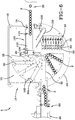
- FIGS. 2-6 One exemplary embodiment of an intermittent motion checkweigher 5 of the present invention is depicted in FIGS. 2-6 .
- the checkweigher 5 includes a substantially rigid frame 10 for supporting various working components.
- the frame 10 may be constructed of any material and by any technique known the art as being suitable for such a purpose.
- Leveling components 15 and/or other mounting components may be associated with the frame 10 for facilitating proper installation of the checkweigher 5.
- the frame also supports a top plate 20, which provides the surface upon which products to be weighed are supported as they travel through the checkweigher 5.
- the top plate 20 underlies a portion of a product transport wheel 25, which is described in more detail below.
- the top plate 20 is shown to be substantially round in shape in this particular embodiment, but other shapes are also possible as long as the top plate is able to provide the required support surface for products to be weighed by the checkweigher 5.
- the top plate 20 may be constructed from a variety of materials, including without limitation, metals, plastics and composites. However, the selected material should exhibit sufficient strength and rigidity to support any products to be weighed by the checkweigher 5.
- the top plate of certain embodiments of the present invention may be manufactured from a low-friction material or may include a low-friction coating on the product support surface thereof to facilitate product movement.
- a product transport wheel 25 resides and rotates above the top plate 20.
- the product transport wheel 25 is supported and rotated by a drive motor 45 that is mounted beneath the product transport wheel.
- the drive motor 45 is mounted to a portion of the frame 10, but other mounting techniques may also be possible.
- the drive motor 45 may be any motor that can be indexed as described below.
- the drive motor 45 is an electric servo motor, which would be quite familiar to one of skill in the art.
- the product transport wheel 25 may be comprised of two discrete plates separated by spacers (as best shown in FIG. 2 ), or may be constructed as a solid plate.
- the former construction obviously reduces the weight of the product transport wheel 25, but it is possible that certain heavier products may benefit from the use of a solid wheel.
- the product transport wheel 25 may be manufactured from a variety of materials, as long as the selected material exhibits sufficient strength and rigidity, and meets any particular requirements associated with the environment in which the checkweigher 5 is installed. For example, certain applications, such as those in the pharmaceutical and food industries, may require the use of particular materials to facilitate cleaning and minimize contamination.
- a product transport wheel of a checkweigher of the present invention is provided with a plurality of product retention pockets that extend inward from the circumferential edge of the wheel.
- the number of product retention pockets may vary depending on the size of the products to be weighed and the diameter of the wheel.
- the inward extending distance (depth) of the product retention pockets of a checkweigher of the present invention may be varied according to the number of products to be simultaneously weighed by the checkweigher. Therefore, while the depth of the product retention pockets 30 shown in the particular checkweigher 5 of FIGS. 2-6 is sufficient to simultaneously retain eight products, it should be understood that the product retention pockets may be designed to retain a lesser or greater number of products (which may, or may not, require a change in the size of the product transport wheel 25 ). For example, in certain applications, it may be desirable that each product retention pocket retains only one product.
- Embodiments of the present invention may also include intermediate product retention pockets (not shown) of reduced depth located between product retention pockets of normal (full) depth. This would allow a given product transport wheel to simultaneously retain a greater number of products than would be possible if only full depth retention pockets were provided.
- the drive motor may be programmed to index the product transport wheel in what may be described as half steps, to allow for weighing of products retained in the intermediate product retention pockets.
- the use of intermediate product retention pockets may also improve handling of tall products because both acceleration and deceleration of the product transport wheel would be accordingly reduced by the reduction in indexing step distance.
- Intermediate product retention pockets may be used with a product transport wheel having full depth product retention pockets of offset orientation (as described in more detail below).
- such a product transport wheel 25 may be provided with a plurality of offset product retention pockets 30.
- offset is intended to mean that the product retention pockets 30 do not extend radially toward the center of the product transport wheel 25. Rather, each product retention pocket 30 extends angularly inward some distance along a path that, if extended, would form a chord connecting two non-diametrically opposed points on the circumference of the product transport wheel 25.
- offset product retention pockets allows the in-feed conveyor and discharge conveyor used with the associated checkweigher to also be offset, which permits for installation of the checkweigher into a production line without the need to cut into an existing conveyor.
- the ability to use offset in-feed and discharge conveyors also allows the in-feed conveyor velocity to be different from the discharge conveyor velocity.
- Employing a higher discharge conveyor velocity allows a group of products to be discharged from the product transport wheel more quickly. As product discharge is typically the bottleneck point for an intermittent motion checkweigher of the present invention, this allows for faster indexing and weighing of products than would otherwise be possible with a single conveyor.
- Employing a higher discharge conveyor velocity also provides greater flexibility for processing tall, difficult to handle, or unstable products.
- a higher discharge conveyor velocity may also be employed to separate products for easier downstream rejection of individual products. Offsetting the in-feed conveyor and discharge conveyors also allows the drive motor to be mounted below the product transport wheel without interference.
- offset product retention pockets permits a greater number of retention pockets to be placed in a single product transport wheel, which allows for the retention of a greater number of products than would be possible using a wheel of like diameter having radial retention pockets. Consequently, it may be possible to employ a product transport wheel of reduced diameter, which results in a wheel of less weight and may permit the use of a smaller drive motor.
- the checkweigher 5 is shown in FIGS. 2-8 in conjunction with an in-feed conveyor 35 and a discharge conveyor 40.
- the in-feed conveyor 35 and discharge conveyor 40 are not part of the present invention, but such devices will generally be used in conjunction therewith. It is to be realized that conveyors used in various installations of a checkweigher of the present invention may be similar to or quite different from the conveyors 35, 40 depicted in the drawing figures, as the design, appearance and construction of such conveyors may be largely dependent on the products transported thereby. Further, devices other than traditional conveyors may be used to supply products to and discharge products from a checkweigher of the present invention. Consequently, a checkweigher of the present invention is in no way limited to use with an in-feed conveyor 35 and discharge conveyor 40 like that shown in the drawing figures.
- the in-feed and discharge conveyors 35, 40 are aligned with selected product retention pocket positions so as to define the locations at which products P will be introduced to and removed from this particular checkweigher installation.
- the in-feed and discharge conveyors may be arranged at an angle that results in a change in the direction of product flow (see e.g., FIG. 7 ).
- both the in-feed conveyor 35 and discharge conveyor 40 extend beneath the product transport wheel 25 by some distance.
- the top plate 20 is designed to accommodate passage of the conveyors 35, 40.
- the distance by which the in-feed and discharge conveyors extend beneath a product transport wheel may be adjusted based on the depth of the product retention pockets thereof. Alternatively, this distance may be selected so as to function with any product transport wheel having product retention pockets, as is best illustrated in FIG. 3 .
- allowing the product transport wheel 25 to overlie the in-feed conveyor 35 in the manner shown and described facilitates feeding of products P fully into a waiting product retention pocket 30.
- allowing the product transport wheel 25 to overlie the discharge conveyor 35 in the manner shown and described facilitates discharge of all products P from a product retention pocket 30 onto the discharge conveyor 40.
- products P are directed by the in-feed conveyor 35 into an open product retention pocket 30 of the product transport wheel 25 that is located at position A (i.e., aligned with the in-feed conveyor).
- the products P will advance until the product retention pocket 30 is filled.
- the products P will advance until the product retention pocket 30 holds eight products.
- Once the product retention pocket 30 is full products will begin to stack up at the entrance to the product retention pocket 30 while awaiting advancement of the product transport wheel 25 and alignment of the next open product retention pocket 30 with the in-feed conveyor 35.
- the product retention pocket filling process repeats, as it will each time the product transport wheel 25 indexes and there are products in queue.
- step is intended to mean movement of a product transport wheel such that a product retention pocket thereof is moved from its current position to the position then occupied by the product retention pocket immediately clockwise thereof. Steps comprising other degrees of rotation may be possible in other embodiments of the present invention. Further, product transport wheel indexing may proceed in a counterclockwise direction in other embodiments.
- each indexing movement of the product transport wheel 25 results in advancement of the next open product retention pocket 30 to position A, and advances the previously filled product retention pocket one step toward the weighing devices 50 and the discharge conveyor 40.
- the weighing devices 50 are located at position B. Therefore, once a product retention pocket 30 has been filled, weighing thereof will occur after the product transport wheel 25 has indexed three steps. While weighing occurs in this example after the product transport wheel 25 has advanced three steps, it should be understood by one of skill in the art that the weighing device(s) of other embodiments of a checkweigher of the present invention may be alternatively located such that weighing occurs after a greater or lesser number of steps. Obviously, however, weighing must occur prior to the products reaching the location of the discharge conveyor associated therewith.
- the checkweigher 5 includes a number of independent weighing devices 50 for weighing the products P. As this checkweigher 5 is designed to weigh each of the products P in a product retention pocket 30, eight weighing devices are provided. Other numbers of weighing devices may be present in other embodiments of the present invention. Additionally, should it be desired to use a checkweigher of the present invention to provide the collective weight of all the products in a product retention pocket, a single weighing device of sufficient size and capacity may be provided.
- each weighing device is mounted beneath the top plate 20 on a weighing device support base 85 or similar structure and includes an actuation arm 55 having a product contacting element 60 (e.g., weighpan) that protrudes into an opening 65 in the top plate.
- the openings 65 are dimensioned to be slightly larger than the overall foot print presented by a bottom surface of the products P to be weighed and are positioned such that the products are fully supported by the weighing devices 50 during the weighing operation without interference or influence from the top plate 20.
- the position of the product contacting elements 60 of this exemplary embodiment can be seen to coincide with position B of the product retention pockets 30.
- All of the weighing devices 50 of this exemplary checkweigher 5 are shown to be located at one indexing location of the product transport wheel 25 so as to weigh all the products in a given product retention pocket 30 at that location.
- other embodiments are also possible.
- weighing devices may be distributed such that a different pair of the eight products in a given product retention pocket are weighed at four different product transport wheel indexing positions.
- the weighing of products in this manner may occur in any order and does not require that the products being weighed are adjacent.
- Such an arrangement may be advantageous when weighing device mounting space at any single product transport wheel indexing position is limited.
- the weighing devices 50 are capable of very quickly providing a weight reading of the products P in the corresponding product retention pocket 30 of the product transport wheel 25. Consequently, the product transport wheel 25 may index quite rapidly while still permitting the products P to be weighed while in a static condition.
- the product transport wheel of a typical checkweigher of the present invention may index at a rate of between approximately 40-80 steps per minute. Faster and slower indexing rates are also possible, however, and the particular rate selected may depend on the product being weighed, the product discharge rate, the diameter and/or weight of the product transport wheel, etc.
- the weighing devices 50 are re-zeroed at some interval. Re-zeroing of the weighing devices 50 may be accomplished by a number of techniques.
- One exemplary static technique can be better understood by reference to the exemplary checkweigher 5 as illustrated particularly in FIGS. 2-3 and 6 .
- one product retention pocket 30 Z is blocked off with a plate 165 or by another suitable mechanism such that no products P may enter or be retained in the retention pocket. Consequently, when the product transport wheel 25 advances the product retention pocket 30 Z to the position of the weighing devices 50 (i.e., to position B ), the weighing devices will perform a weighing operation without any weight being supported by the product contacting elements 60.
- a static recalibration of the weighing devices 50 may be accomplished in a similar manner. That is, a second product retention pocket may be blocked off (not shown) with respect to receiving and retaining products to be weighed. In this second retention pocket is located a number (eight in this case) of calibration weights of known mass. Consequently, when the product transport wheel 25 advances the product retention pocket containing the calibration weights to the position of the weighing devices 50 (i.e., to position B ), the resulting weight readings produced by the weighing devices are used to establish a new calibration factor (if necessary). Thus, this technique produces a static recalibration of the weighing devices 50 once per every complete rotation of the product transport wheel 25.
- a product transport wheel can be designed such that products retained in the product retention pockets thereof are sufficiently displaced from the center of the wheel so as to afford sufficient time to re-zero the weighing devices between wheel indexing steps. That is, the farther toward the periphery of the product transport wheel the products are maintained, the greater the distance the products must travel between each step of the wheel and the greater the time interval between the departure of one product (or one group of products) from the weighing device(s) and the arrival of the next product (or group of products) thereto.
- a product transport wheel may be provided with a re-zeroing product retention pocket where only the distal half (or some other portion) thereof is sealed off, while the proximal half (or other remaining portion) is allowed to receive and retain products to be weighed.
- the weighing devices nearer the center of the product transport wheel i.e., the weighing devices associated with the blocked portion of the re-zeroing product retention pocket
- the weighing devices associated with the product-containing portion of the re-zeroing product retention pocket may be dynamically re-zeroed between indexing steps of the product transport wheel.
- This technique still results in a number of lost product retention spots in the partially blocked re-zeroing product retention pocket.
- the combined technique also allows the remaining product retention pockets to extend farther into the wheel and to retain more products than may be possible with a fully dynamic re-zeroing procedure.
- a calibration product retention pocket may have only the distal half (or some other portion) thereof sealed off, while the proximal half (or other remaining portion) is allowed to receive and retain products to be weighed.
- Calibration weights of known mass would then be placed in the sealed off portion of the retention pocket for use in the static recalibration of the weighing devices associated with the sealed portion of the retention pocket.
- the weighing devices associated with the open portion of the calibration product retention pocket would then be recalibrated by a dynamic calibration principle between indexing steps of the product transport wheel using the known mass as a calibration weight.
- a checkweigher of the present invention is not limited to the use of one particular weighing device.
- weighing devices associated with a checkweigher of the present invention may include, without limitation, load cells of the strain gage variety, force restoration type weigh cells, or devices employing other technologies where actuation of the device results in a weight determination.
- a product sensor 70 may be located near loading/in-feed position A to detect the presence of one or more products that will collect on the in-feed conveyor 35 once the product retention pocket 30 at the loading position is filled.
- the sensor may be monitored by a controller 75.
- the drive motor 45 indexes the product transport wheel 25 as described above.
- the drive motor 45 may be operated by the controller 75, or the drive motor may have its own controller, which is activated upon receipt of a signal from the senor 70. Indexing of the product transport wheel 25 will repeat each time the sensor 70 becomes blocked for the requisite amount of time. Weighing of products P by the checkweigher 5 will thus proceed as previously described.
- a rejecter 80 may be associated with the checkweigher 5 to remove products of improper weight from the product stream.
- the rejecter 80 may include an actuator that can be energized to push, pull or otherwise remove a rejected product P from the discharge conveyor 40.
- the rejecter may comprise one or a plurality of trap doors or similar devices that are located in the top plate of the checkweigher. In this manner, rejected products may be removed from the product stream before the rejected products even reach the discharge conveyor. Such a technique ensures that products rejected for improper weight do not accidentally remain in the product stream.
- the in-feed conveyor associated with a checkweigher of the present invention is also typically operated at a high velocity, thereby resulting in products being deposited into the waiting product retention pocket in rapid succession.
- a checkweigher of the present invention may employ a specially designed product stop and/or product guide.
- the exemplary checkweigher 5 can be seen to include a product stop plate assembly 90.
- the product stop plate assembly 90 is positioned between the product transport wheel 25 and the top plate 20 and extends across the in-feed conveyor 35 at a location wherein a bumper portion thereof substantially coincides with the closed end of a product retention pocket 30 when the product retention pocket is in position A.
- This particular product stop plate assembly 90 includes a mounting bracket 95 and a bumper 100.
- the bumper 100 is preferably constructed of an elastomeric material that is capable of absorbing the contact forces produced by the incoming products P and, thus, minimizes bounce back thereof.
- Other embodiments of such a stop plate assembly may also include one or more springs or similar devices mounted between the bumper and the mounting bracket to further absorb the forces of incoming products.
- the first product P entering the product retention pocket 30 is advanced toward the closed end thereof until it contacts the bumper 100 of the product stop plate assembly 90.
- the material of the bumper 100 absorbs much of the energy produced by the moving product, such that its tendency to return upstream is greatly diminished.
- the contact force is transmitted through the downstream products and absorbed by the bumper 100. Consequently, the bumper 100 is able to minimize the bounce back tendency of all products that enter the product retention pocket 30.
- a side guide may also be employed to help control products entering a product retention pocket of a checkweigher product transfer wheel at high speed.
- a side guide 105 is shown to be installed to the exemplary checkweigher 5 of FIG. 6 .
- This particular side guide 105 includes a plate 110 that resides between the top plate 20 and product transport wheel 25 and extends along the in-feed conveyor 35.
- the plate 110 is pivotally attached 115 to the frame 10 or another portion of the checkweigher 5 near its upstream end.
- Such a pivotal attachment allows the plate 110 to be rotated and to be placed at an angle with respect to the in-feed conveyor 35 and to products P entering the product retention pocket 30 thereon.
- the products P are forced into increasing contact with the plate 110 of the side guide 105 as the products move farther into the product retention pocket 30. This contact also helps to reduce the velocity of and improve control over the products.
- the downstream end of the side guide plate 110 may be disposed against or very near the bumper 100 of the product stop plate assembly 90.
- the top plate 20 of the checkweigher 5 may be provided with features 120 such as runners, slots, grooves, holes, etc., that extend through the top plate. While not essential, such features may be nonetheless advantageous with regard to allowing spilled or excess product to pass through the top plate rather than building up thereon. When present, such features may be disposed over the entire top plate or over only a portion of a top plate of a checkweigher of the present invention. Such features should be of a size and/or shape that prohibits products from passing therethrough as the products are moved across the top plate by the associate product transport wheel.
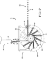
- FIG. 7 An alternative installation of the checkweigher 5 of FIGS. 2-6 is depicted in FIG. 7 .
- the checkweigher 5, and the in-feed and discharge conveyors 35, 40 are the same as those shown in FIGS. 1-5 .
- the discharge conveyor 40 has been rotated clockwise 90° from the position thereof shown in FIGS. 1-5 . Consequently, products P removed by the discharge conveyor 40 will be transported in a direction substantially perpendicular to the direction of travel of the in-feed conveyor 35.
- Such an installation may be desirable for a variety of reasons, including but not limited to plant or process line layout, and space constraints.
- the discharge conveyor may also be placed in other positions, such as any of the product retention pocket 30 index positions existing between weighing position B and the in-feed conveyor 35.
- top plate features 115 like those described above and shown in FIG. 6 may be more desirable when a checkweigher of the present invention is used in conjunction with a filler. Because the drive motor of a checkweigher of the present invention is located beneath the product transport wheel, the area overhead of the product transport wheel is generally open. This allows for the possibility of using a filler in conjunction with a checkweigher of the present invention. The filler is operative to fill open containers processed and weighed by the checkweigher. Such fillers would be well known to one of skill in the art.
- a checkweigher 125 of the present invention is provided with a product transport wheel 130 having a plurality of product retention pockets 135 in a similar manner to the checkweigher 5 of FIGS. 2-6 .
- the checkweigher 125 is also operable to weigh products of interest in much the same fashion as described above with respect to the exemplary checkweigher 5 of FIGS. 2-6 .
- the products are open containers 150.
- the undermount motor design of the checkweigher 125 advantageously allows the use of a filler 155 (which is only schematically depicted for purposes of simplicity) to fill the containers 150 with a given material (e.g., powder, liquid, tablets, etc.) as the containers are advanced beneath the filler by the product transport wheel 130 of the checkweig her.
- a filler 155 which is only schematically depicted for purposes of simplicity
- this particular checkweigher 125 includes two sets of weighing devices 140, 145.
- a first set of weighing devices 140 is shown to reside at product retention pocket 135 location T (i.e., the tare location).
- a second set of weighing devices 145 is shown to reside at product retention pocket 135 location G (i.e., the gross weight location).
- the first set of weighing devices 140 weighs (tares) the empty containers 150 in the corresponding product retention pocket 135 prior to filling of the containers by the filler 155.
- the product transport wheel 130 subsequently advances the tared containers 150 until they reside beneath the filler 155, which will typically resides above an indexing position of the product transport wheel.
- the filler 155 resides one step from the first set of weighing devices 140, at position F.
- a filler may be placed a greater number of steps from the taring location.
- the filler 155 is operated to fill each container by some amount with a corresponding material. Filling preferably occurs within the interval between indexing steps of the product transport wheel 130. Further indexing of the product transport wheel 130 then advances the filled group of containers toward the second set of weighing devices 145.
- the second set of weighing devices 145 resides two steps from the filler 155 location. In other embodiments of the present invention, the second set of weighing devices may be placed a greater or lesser number of steps from the location of the filler.
- the second set of weighing devices 145 determines the gross weight of the filled containers 150 (i.e., the total weight of each container and the material deposited therein by the filler). After weighing, further indexing of the product transport wheel 130 subsequently advances the filled containers 150 until they reach the discharge position D and are removed from the product transport wheel 125 by the discharge conveyor 160.
- the discharge conveyor 160 resides one step from the second set of weighing devices 145. In other embodiments of the present invention, a discharge conveyor may be placed a greater number of steps from a second set of weighing devices.
- a checkweigher of the present invention may be used with products of other cross-sectional shapes.
- a checkweigher of the present invention may be used to weigh products of square, rectangular or oval cross-section. Such may be accomplished by designing the product retention pockets of the checkweigher product transport wheel to accommodate the particular shape of the products of interest. Whatever the shape of the products of interest, however, it is preferred that the product retention pockets are designed to prevent product-to-product contact therein. Maintaining a slight gap between the products within a given product retention pocket prevents one product from influencing the weight reading of an adjacent product.
Landscapes
- Physics & Mathematics (AREA)
- General Physics & Mathematics (AREA)
- Sorting Of Articles (AREA)
Claims (16)
- Eine intermittierend bewegbare Vorrichtung für die Gewichtsprüfung von Produkten (P), umfassend:ein Untergestell (10);eine von dem Untergestell (10) getragene Tischplatte (20), welche als Auflagefläche für die Produkte dient;ein drehbares Transportrad (25, 130), welches dazu dient, die Produkte (P) einem Transportpfad entlang durch einen Wägevorgang zu bewegen;eine Vielzahl von zum Aufnehmen der Produkte (P) dienenden Aufnahmeabteilen (30, 135); undmindestens eine Wägevorrichtung (50, 140, 145) mit mindestens einem innerhalb einer entsprechenden Ausnehmung (65) in der vorgenannten Tischplatte (20) freiliegenden Betätigungsbereich, wobei die mindestens eine Wägevorrichtung (50, 140, 145) entlang des genannten Pfades angeordnet ist und den Zweck hat, eine Gewichtsanzeige des Produkts (P) bereitzustellen,dadurch gekennzeichnet, dass die zum Aufnehmen der Produkte (P) dienenden Aufnahmeabteile (30, 135) so auf dem Transportrad (25, 130) angeordnet sind, dass sie sich unter einem Winkel ins Innere des Transportrades (25, 130) hinein erstrecken und gegenüber einer radial zur Mitte hin verlaufenden Richtung seitlich versetzt sind, und ferner gekennzeichnet durch das Vorhandensein eines Antriebsmotors (45), welcher sich unterhalb des Transportrades (25, 130) befindet und dazu ausgelegt ist, die intermittierende Drehbewegung des Transportrades (25, 130) zu erzeugen.
- Die Vorrichtung nach Anspruch 1, wobei:
jedes Aufnahmeabteil (30, 135) eine langgestreckte Form hat und dazu ausgebildet ist, gleichzeitig eine Vielzahl von Produkten (P) zu aufzunehmen, unter Einhaltung eines geringfügigen Abstandes zwischen den innerhalb eines gegebenen Aufnahmeabteils (30, 135) befindlichen Produkten, um bei der Gewichtsermittlung eine gegenseitige Beeinflussung zwischen benachbarten Produkten (P) zu vermeiden. - Die Vorrichtung nach Anspruch 2, wobei:
die Anzahl der vorhandenen Wägevorrichtungen (50, 140, 145) der Anzahl der Produkte (P) entspricht, zu deren gleichzeitiger Aufnahme jedes der Aufnahmeabteile (30, 135) ausgebildet ist. - Die Vorrichtung nach einem der Ansprüche 1 bis 3, wobei:
der Antriebsmotor (45) das Transportrad (25, 130) schrittweise von einer Position zur nächsten bewegt, sodass jeder Schritt ein neues Aufnahmeabteil (30, 135) in eine mit der mindestens einen Wägevorrichtung (50, 140, 145) ausgerichtete Position versetzt. - Die Vorrichtung nach einem der Ansprüche 1 bis 3, wobei:
das Transportrad (25, 130) zwei durch eine Anzahl von Abstandshaltern getrennte Scheiben umfasst oder als ein massiver Scheibenkörper ausgebildet ist. - Die Vorrichtung nach einem der Ansprüche 1 bis 3, wobei:
der Antriebsmotor (45) unterhalb der Tischplatte angeordnet ist. - Die Vorrichtung nach einem der Ansprüche 1 bis 3, ferner umfassend:
eine Vielzahl von Ausnehmungen (65) in der Tischplatte (20), um den Durchtritt von verschüttetem oder überschüssigem Material zu ermöglichen. - Die Vorrichtung nach einem der Ansprüche 1 bis 3, ferner umfassend:
eine im Bereich einer Zufuhrposition des Transportrades (25, 130) befindliche Anschlagsplattenbaugruppe (90) mit dem Zweck, bei der Ankunft eines Produktes (P) in einem entsprechenden Aufnahmeabteil (30, 135) die Tendenz des Zurückprallens in der Gegenrichtung des Transportstromes zu vermindern. - Die Vorrichtung nach Anspruch 8, wobei:
die Anschlagsplattenbaugruppe (90) einen gummielastischen Puffer (100) umfasst. - Die Vorrichtung nach einem der Ansprüche 1 bis 3, wobei:
ein Produktaufnahmeabteil (30, 135) des Produkttransportrades (25, 130) mit mindestens einem Eichgewicht von bekanntem Massenbetrag versehen ist, welches im Bedarfsfalle dazu verwendet wird, eine an der gleichen Stelle wie das Eichgewicht befindliche Wägevorrichtung (50, 140, 145) nachzueichen. - Die Vorrichtung nach einem der Ansprüche 1 bis 3, wobei:
ein Produktaufnahmeabteil (30, 135) des Produkttransportrades (25, 130) in der Weise blockiert ist, dass der Eintritt und die Aufnahme von Produkten (P) verhindert wird und dass jedesmal, wenn sich das blockierte Aufnahmeabteil an der gleichen Stelle wie die Wägevorrichtungen (50, 140, 145) befindet, die Anwesenheit des blockierten Aufnahmeabteils eine statische Nullpunktsnachstellung der betreffenden Wägevorrichtung (50, 140, 145) zur Folge hat. - Die Vorrichtung nach einem der Ansprüche 1 bis 3, wobei:
die Aufnahmeabteile (30, 135) geeignet dimensioniert sind, um die Nullpunktsnachstellung der Wägevorrichtungen (50, 140, 145) während jeder Bewegungsphase des Transportrades (25, 130) zu ermöglichen, indem die Position der Produktaufnahmeabteile (30, 135) und der darin befindlichen Produkte (P) kontrolliert wird, wobei ein hinreichend langes Zeitintervall zwischen aufeinanderfolgenden Belegungen der Wägevorrichtungen (50, 140, 145) zur Verfügung gestellt wird, um in jedem Stellschritt oder über eine vorbestimmte Folge von Stellschritten des Produkttransportrades (25, 130) eine Nullpunktsnachstellung der Wägevorrichtungen (50, 140, 145) zu ermöglichen. - Die Vorrichtung nach einem der Ansprüche 1 bis 3, ferner umfassend:
eine oberhalb des Transportrades (130) angeordnete Abfüllvorrichtung (155), welche dazu dient, offene Produktbehälter mit einem vorgesehenen Material zu füllen, wenn die offenen Produktbehälter durch das Transportrad (130) unter der Abfüllvorrichtung (155) positioniert worden sind. - Die Vorrichtung nach Anspruch 13, wobei:
mindestens eine Wägevorrichtung (140) geeignet angeordnet ist, um einen offenen Produktbehälter zu wägen bevor der betreffende offene Produktbehälter die Abfüllvorrichtung (155) erreicht, und wobei ferner mindestens eine Wägevorrichtung (145) geeignet angeordnet ist, um einen Produktbehälter zu wägen nachdem der betreffende Produktbehälter durch die Abfüllvorrichtung (155) befüllt worden ist. - Die Vorrichtung nach einem der Ansprüche 1 bis 3, ferner umfassend:eine Zufuhrvorrichtung (35), welche dazu dient, die Produkte (P) zu den Aufnahmeabteilen (30, 135) des Transportrades (25, 130) zu bringen; undeine Entladevorrichtung (40, 160), welche dazu dient, die Produkte (P) von den Aufnahmeabteilen (30, 135) des Transportrades (25, 130) zu entfernen, wobei die Entladevorrichtung (40, 160) mit grösserer Geschwindigkeit arbeitet als die Zufuhrvorrichtung (35).
- Eine intermittierend bewegbare Vorrichtung für das Wägen von Behältern, umfassend:ein Untergestell (10);eine von dem Untergestell (10) getragene Tischplatte (20), welche als Auflagefläche für die zu wägenden Behälter dient;gekennzeichnet durch:ein über der Tischplatte (20) angeordnetes drehbares Behältertransportrad (130) mit einer Vielzahl von Behälteraufnahmeabteilen (135), welche auf dem Transportrad (130) so angeordnet sind, dass sie sich unter einem Winkel ins Innere des Transportrades (130) hinein erstrecken und gegenüber einer radial zur Mitte hin verlaufenden Richtung seitlich versetzt sind, und welche zur Aufnahme der Behälter dienen, die durch das Behältertransportrad (130) über die Tischplatte (20) und durch einen Wägevorgang der Vorrichtung bewegt werden;einen Antriebsmotor (45), welcher sich unterhalb des Behältertransportrades (130) befindet und dazu ausgelegt ist, die intermittierende Drehbewegung des Transportrades (25, 130) zu erzeugen:eine oberhalb des Behältertransportrades (130) angeordnete Abfüllvorrichtung (155), welche dazu dient, Behälter mit einem vorgesehenen Material zu befüllen, wenn die Behälter durch das Transportrad (130) unter der Abfüllvorrichtung (155) positioniert worden sind;mindestens eine erste Wägevorrichtung (140) mit mindestens einem innerhalb einer entsprechenden Ausnehmung in der vorgenannten Tischplatte (20) freiliegenden Betätigungsbereich, wobei die mindestens eine erste Wägevorrichtung (140) entlang des Pfades angeordnet ist, auf welchem ein zu wägender Behälter durch das Behältertransportrad bewegt wird, und wobei die mindestens eine erste Wägevorrichtung (140) den Zweck hat, einen offenen Behälter zu wägen bevor derselbe die Abfüllvorrichtung (155) erreicht hat; undmindestens eine zweite Wägevorrichtung (145) mit mindestens einem innerhalb einer entsprechenden Ausnehmung in der vorgenannten Tischplatte freiliegenden Betätigungsbereich, wobei die mindestens eine zweite Wägevorrichtung (145) entlang des Pfades angeordnet ist, auf welchem ein zu wägender Behälter durch das Behältertransportrad (130) bewegt wird, und wobei die mindestens eine zweite Wägevorrichtung (145) den Zweck hat, den besagten Behälter zu wägen nachdem derselbe durch die Abfüllvorrichtung (155) befüllt worden ist.
Applications Claiming Priority (2)
| Application Number | Priority Date | Filing Date | Title |
|---|---|---|---|
| US12/641,174 US8247711B2 (en) | 2009-12-17 | 2009-12-17 | Intermittent motion checkweigher with offset product pockets |
| PCT/US2010/061035 WO2011084689A1 (en) | 2009-12-17 | 2010-12-17 | Intermittent motion checkweigher with offset product pockets |
Publications (2)
| Publication Number | Publication Date |
|---|---|
| EP2513616A1 EP2513616A1 (de) | 2012-10-24 |
| EP2513616B1 true EP2513616B1 (de) | 2018-06-20 |
Family
ID=43644415
Family Applications (1)
| Application Number | Title | Priority Date | Filing Date |
|---|---|---|---|
| EP10798234.0A Active EP2513616B1 (de) | 2009-12-17 | 2010-12-17 | Kontrollwaage mit intermittierender bewegung und versetzten produktschalen |
Country Status (4)
| Country | Link |
|---|---|
| US (1) | US8247711B2 (de) |
| EP (1) | EP2513616B1 (de) |
| CN (1) | CN102656429B (de) |
| WO (1) | WO2011084689A1 (de) |
Families Citing this family (15)
| Publication number | Priority date | Publication date | Assignee | Title |
|---|---|---|---|---|
| ITUD20070156A1 (it) * | 2007-09-04 | 2009-03-05 | Baccini S P A | Disositivo di posizionamento per posizionare uno o piu' wafer a base di silicio, in particolare per celle fotovoltaiche, in un'unita' di deposizione del metallo |
| US8499919B2 (en) * | 2010-08-30 | 2013-08-06 | Health Robotics, S.r.l. | Machine for the production of pharmaceutical products |
| ITBO20110105A1 (it) * | 2011-03-04 | 2012-09-05 | Ima Life Srl | Dispositivo per la pesatura di contenitori oblunghi alimentati lungo una linea di convogliamento |
| SG10201601705VA (en) * | 2011-09-06 | 2016-04-28 | Kocher Plastik Maschinenbau Gmbh | Method for establishing the presence of specified characteristics of a container product and device for performing said method |
| ITBO20110551A1 (it) * | 2011-09-27 | 2013-03-28 | Ima Life Srl | Gruppo e metodo per pesare contenitori |
| CN103496458B (zh) * | 2013-10-11 | 2016-02-10 | 忠华集团有限公司 | 筒纱自动称重包装装置 |
| ITMI20150570A1 (it) * | 2015-04-21 | 2016-10-21 | Ima Spa | Metodo di pesatura di contenitori di sostanze farmaceutiche, medicali, alimentari o simili |
| US9669951B2 (en) * | 2015-10-12 | 2017-06-06 | Carefusion Germany 326 Gmbh | Systems and methods for packaging devices |
| IT201800006114A1 (it) * | 2018-06-07 | 2019-12-07 | Metodo per la manipolazione ed il controllo di prodotti o di materia prima in blocchi o lastre | |
| CN109761182B (zh) * | 2019-02-01 | 2021-04-06 | 楚天科技股份有限公司 | 一种大输液玻瓶灌装的称重检测方法 |
| USD951116S1 (en) | 2019-04-30 | 2022-05-10 | Illinois Tool Works Inc. | Checkweigher |
| US11247889B2 (en) * | 2019-04-30 | 2022-02-15 | Twin Monkeys Beverage Systems, Inc. | Auto-calibrating beverage fill station |
| IT201900007266A1 (it) * | 2019-05-27 | 2020-11-27 | Ima Spa | Apparecchiatura e procedimento di pesatura, preferibilmente per pesare uno o piu’ contenitori configurati per contenere prodotti fluidi, solidi o in polvere, in una macchina di riempimento automatico dei suddetti contenitori. |
| CN112499250A (zh) * | 2020-11-26 | 2021-03-16 | 平阳县天卫机械有限公司 | 一种螺栓机用排序式输出装置 |
| EP4332520B1 (de) * | 2022-08-29 | 2025-08-06 | Anritsu Corporation | Fördervorrichtung für gegenstände |
Family Cites Families (15)
| Publication number | Priority date | Publication date | Assignee | Title |
|---|---|---|---|---|
| US2570198A (en) * | 1946-04-19 | 1951-10-09 | American Can Co | Container transfer mechanism |
| GB1424344A (en) | 1972-08-04 | 1976-02-11 | Metal Box Co Ltd | Handling articles |
| FR2402580A1 (fr) * | 1977-09-09 | 1979-04-06 | Serac Sa | Dispositif de correction automatique d'un carrousel de remplissage a dosage ponderal |
| US4407379A (en) * | 1981-06-12 | 1983-10-04 | Diffracto Ltd. | High accuracy filling machines |
| US4682664A (en) * | 1985-07-31 | 1987-07-28 | Canadian Corporate Management Co., Ltd. | Load sensing systems for conveyor weigh scales |
| US4715412A (en) * | 1985-08-22 | 1987-12-29 | Bemis Company, Inc. | Method and apparatus for check-weighing charges for containers |
| US5004093A (en) * | 1989-11-08 | 1991-04-02 | Charles Packaging Corporation | Straight line sorting and/or fill-to-weigh machine |
| JP2972967B2 (ja) * | 1991-02-26 | 1999-11-08 | アンリツ株式会社 | 計量装置 |
| IT1264247B1 (it) * | 1993-10-22 | 1996-09-23 | Mg 2 Spa | Metodo per la determinazione del peso di prodotti farmaceutici e macchina per la dosatura di prodotti farmaceutici utilizzante |
| DE19513103A1 (de) * | 1995-04-07 | 1996-10-10 | Buehler Optima Maschf | Vorrichtung und Verfahren zum Befüllen von Behältern |
| US6168004B1 (en) * | 1998-11-05 | 2001-01-02 | Kalish Canada, Inc. | Container distribution apparatus |
| US7331210B2 (en) * | 2005-09-30 | 2008-02-19 | Ronald Dietrich | Conveyor weighbridge with built-in calibration weight |
| ITBO20070641A1 (it) | 2007-09-24 | 2009-03-25 | Ima Libra S R L | Apparato e metodo per pesare contenitori. |
| CN201340295Y (zh) | 2008-12-03 | 2009-11-04 | 上海恒谊制药设备有限公司 | 一种快速的在线称重检测装置 |
| US8237067B2 (en) * | 2009-06-16 | 2012-08-07 | Mettler-Toledo, LLC | Checkweigher with independent scales |
-
2009
- 2009-12-17 US US12/641,174 patent/US8247711B2/en active Active
-
2010
- 2010-12-17 WO PCT/US2010/061035 patent/WO2011084689A1/en not_active Ceased
- 2010-12-17 EP EP10798234.0A patent/EP2513616B1/de active Active
- 2010-12-17 CN CN201080057282.9A patent/CN102656429B/zh active Active
Non-Patent Citations (1)
| Title |
|---|
| None * |
Also Published As
| Publication number | Publication date |
|---|---|
| CN102656429A (zh) | 2012-09-05 |
| US8247711B2 (en) | 2012-08-21 |
| CN102656429B (zh) | 2015-07-01 |
| US20110147097A1 (en) | 2011-06-23 |
| WO2011084689A1 (en) | 2011-07-14 |
| EP2513616A1 (de) | 2012-10-24 |
Similar Documents
| Publication | Publication Date | Title |
|---|---|---|
| EP2513616B1 (de) | Kontrollwaage mit intermittierender bewegung und versetzten produktschalen | |
| CN106660649B (zh) | 用于称重容器的设备 | |
| EP2370044B1 (de) | Maschine und verfahren zum füllen und wiegen von kapseln | |
| US8266874B2 (en) | Weighing device for a packaging machine | |
| EP2605969B1 (de) | Abfüllmaschine und verfahren zum wiegen von artikeln | |
| EP2205489B1 (de) | Vorrichtung und verfahren zum wiegen von behältern | |
| EP2273241B1 (de) | Geräte zum wägen der füllmenge | |
| US6407346B1 (en) | Rotary check weigher | |
| KR20180039056A (ko) | 약제 조제 장치 | |
| EP4251116B1 (de) | Erfassung der wiederauffindung von pillen | |
| ES2857148T3 (es) | Método de pesaje para pesar envases de sustancias farmacéuticas, médicas, alimenticias, o similares | |
| CA2681047A1 (en) | Link apparatus, weighing apparatus using link apparatus, packaging apparatus using link apparatus and weighing and packaging system using link apparatus | |
| EP1582193B1 (de) | Maschine zum Dosieren eines Produktes in Kapseln | |
| US9562803B2 (en) | Material feeder system and method of use | |
| EP2851303B1 (de) | Verfahren zum Wiegen von Behältern in einer Befüllungsmaschine und zugehörige Maschine | |
| EP1941249B1 (de) | Vorrichtung und entsprechendes verfahren zum wägen von behältern | |
| CN103732500B (zh) | 用于输送制药容器、特别是小药瓶的装置 | |
| CN102762962B (zh) | 具有对置轮的称量设备 | |
| EP2615584B1 (de) | Vorrichtung zum Wiegen von flachen, sich bewegenden Objekten | |
| CN115540981A (zh) | 用于称量填充的胶囊的装置和方法 | |
| CN121425608A (zh) | 一种直列式组合秤分料机 | |
| JP7790721B2 (ja) | 薬剤包装装置 | |
| WO2003027617A1 (en) | Device for loading and unloading a weighscale | |
| WO2025003863A1 (en) | Apparatus and method for weighing and feeding capsules | |
| KR980007965A (ko) | 난(卵)선별방법 및 난(卵)선별장치 |
Legal Events
| Date | Code | Title | Description |
|---|---|---|---|
| PUAI | Public reference made under article 153(3) epc to a published international application that has entered the european phase |
Free format text: ORIGINAL CODE: 0009012 |
|
| 17P | Request for examination filed |
Effective date: 20120710 |
|
| AK | Designated contracting states |
Kind code of ref document: A1 Designated state(s): AL AT BE BG CH CY CZ DE DK EE ES FI FR GB GR HR HU IE IS IT LI LT LU LV MC MK MT NL NO PL PT RO RS SE SI SK SM TR |
|
| RAP1 | Party data changed (applicant data changed or rights of an application transferred) |
Owner name: METTLER-TOLEDO, LLC |
|
| DAX | Request for extension of the european patent (deleted) | ||
| GRAP | Despatch of communication of intention to grant a patent |
Free format text: ORIGINAL CODE: EPIDOSNIGR1 |
|
| INTG | Intention to grant announced |
Effective date: 20180202 |
|
| GRAS | Grant fee paid |
Free format text: ORIGINAL CODE: EPIDOSNIGR3 |
|
| GRAA | (expected) grant |
Free format text: ORIGINAL CODE: 0009210 |
|
| AK | Designated contracting states |
Kind code of ref document: B1 Designated state(s): AL AT BE BG CH CY CZ DE DK EE ES FI FR GB GR HR HU IE IS IT LI LT LU LV MC MK MT NL NO PL PT RO RS SE SI SK SM TR |
|
| REG | Reference to a national code |
Ref country code: GB Ref legal event code: FG4D |
|
| REG | Reference to a national code |
Ref country code: IE Ref legal event code: FG4D |
|
| REG | Reference to a national code |
Ref country code: DE Ref legal event code: R096 Ref document number: 602010051424 Country of ref document: DE |
|
| REG | Reference to a national code |
Ref country code: AT Ref legal event code: REF Ref document number: 1010940 Country of ref document: AT Kind code of ref document: T Effective date: 20180715 |
|
| REG | Reference to a national code |
Ref country code: NL Ref legal event code: MP Effective date: 20180620 |
|
| PG25 | Lapsed in a contracting state [announced via postgrant information from national office to epo] |
Ref country code: SE Free format text: LAPSE BECAUSE OF FAILURE TO SUBMIT A TRANSLATION OF THE DESCRIPTION OR TO PAY THE FEE WITHIN THE PRESCRIBED TIME-LIMIT Effective date: 20180620 Ref country code: NO Free format text: LAPSE BECAUSE OF FAILURE TO SUBMIT A TRANSLATION OF THE DESCRIPTION OR TO PAY THE FEE WITHIN THE PRESCRIBED TIME-LIMIT Effective date: 20180920 Ref country code: FI Free format text: LAPSE BECAUSE OF FAILURE TO SUBMIT A TRANSLATION OF THE DESCRIPTION OR TO PAY THE FEE WITHIN THE PRESCRIBED TIME-LIMIT Effective date: 20180620 Ref country code: BG Free format text: LAPSE BECAUSE OF FAILURE TO SUBMIT A TRANSLATION OF THE DESCRIPTION OR TO PAY THE FEE WITHIN THE PRESCRIBED TIME-LIMIT Effective date: 20180920 Ref country code: LT Free format text: LAPSE BECAUSE OF FAILURE TO SUBMIT A TRANSLATION OF THE DESCRIPTION OR TO PAY THE FEE WITHIN THE PRESCRIBED TIME-LIMIT Effective date: 20180620 |
|
| REG | Reference to a national code |
Ref country code: LT Ref legal event code: MG4D |
|
| PG25 | Lapsed in a contracting state [announced via postgrant information from national office to epo] |
Ref country code: HR Free format text: LAPSE BECAUSE OF FAILURE TO SUBMIT A TRANSLATION OF THE DESCRIPTION OR TO PAY THE FEE WITHIN THE PRESCRIBED TIME-LIMIT Effective date: 20180620 Ref country code: RS Free format text: LAPSE BECAUSE OF FAILURE TO SUBMIT A TRANSLATION OF THE DESCRIPTION OR TO PAY THE FEE WITHIN THE PRESCRIBED TIME-LIMIT Effective date: 20180620 Ref country code: GR Free format text: LAPSE BECAUSE OF FAILURE TO SUBMIT A TRANSLATION OF THE DESCRIPTION OR TO PAY THE FEE WITHIN THE PRESCRIBED TIME-LIMIT Effective date: 20180921 Ref country code: LV Free format text: LAPSE BECAUSE OF FAILURE TO SUBMIT A TRANSLATION OF THE DESCRIPTION OR TO PAY THE FEE WITHIN THE PRESCRIBED TIME-LIMIT Effective date: 20180620 |
|
| REG | Reference to a national code |
Ref country code: AT Ref legal event code: MK05 Ref document number: 1010940 Country of ref document: AT Kind code of ref document: T Effective date: 20180620 |
|
| PG25 | Lapsed in a contracting state [announced via postgrant information from national office to epo] |
Ref country code: NL Free format text: LAPSE BECAUSE OF FAILURE TO SUBMIT A TRANSLATION OF THE DESCRIPTION OR TO PAY THE FEE WITHIN THE PRESCRIBED TIME-LIMIT Effective date: 20180620 |
|
| PG25 | Lapsed in a contracting state [announced via postgrant information from national office to epo] |
Ref country code: CZ Free format text: LAPSE BECAUSE OF FAILURE TO SUBMIT A TRANSLATION OF THE DESCRIPTION OR TO PAY THE FEE WITHIN THE PRESCRIBED TIME-LIMIT Effective date: 20180620 Ref country code: RO Free format text: LAPSE BECAUSE OF FAILURE TO SUBMIT A TRANSLATION OF THE DESCRIPTION OR TO PAY THE FEE WITHIN THE PRESCRIBED TIME-LIMIT Effective date: 20180620 Ref country code: AT Free format text: LAPSE BECAUSE OF FAILURE TO SUBMIT A TRANSLATION OF THE DESCRIPTION OR TO PAY THE FEE WITHIN THE PRESCRIBED TIME-LIMIT Effective date: 20180620 Ref country code: IS Free format text: LAPSE BECAUSE OF FAILURE TO SUBMIT A TRANSLATION OF THE DESCRIPTION OR TO PAY THE FEE WITHIN THE PRESCRIBED TIME-LIMIT Effective date: 20181020 Ref country code: EE Free format text: LAPSE BECAUSE OF FAILURE TO SUBMIT A TRANSLATION OF THE DESCRIPTION OR TO PAY THE FEE WITHIN THE PRESCRIBED TIME-LIMIT Effective date: 20180620 Ref country code: SK Free format text: LAPSE BECAUSE OF FAILURE TO SUBMIT A TRANSLATION OF THE DESCRIPTION OR TO PAY THE FEE WITHIN THE PRESCRIBED TIME-LIMIT Effective date: 20180620 Ref country code: PL Free format text: LAPSE BECAUSE OF FAILURE TO SUBMIT A TRANSLATION OF THE DESCRIPTION OR TO PAY THE FEE WITHIN THE PRESCRIBED TIME-LIMIT Effective date: 20180620 |
|
| PG25 | Lapsed in a contracting state [announced via postgrant information from national office to epo] |
Ref country code: IT Free format text: LAPSE BECAUSE OF FAILURE TO SUBMIT A TRANSLATION OF THE DESCRIPTION OR TO PAY THE FEE WITHIN THE PRESCRIBED TIME-LIMIT Effective date: 20180620 Ref country code: SM Free format text: LAPSE BECAUSE OF FAILURE TO SUBMIT A TRANSLATION OF THE DESCRIPTION OR TO PAY THE FEE WITHIN THE PRESCRIBED TIME-LIMIT Effective date: 20180620 Ref country code: ES Free format text: LAPSE BECAUSE OF FAILURE TO SUBMIT A TRANSLATION OF THE DESCRIPTION OR TO PAY THE FEE WITHIN THE PRESCRIBED TIME-LIMIT Effective date: 20180620 |
|
| REG | Reference to a national code |
Ref country code: DE Ref legal event code: R097 Ref document number: 602010051424 Country of ref document: DE |
|
| PLBE | No opposition filed within time limit |
Free format text: ORIGINAL CODE: 0009261 |
|
| STAA | Information on the status of an ep patent application or granted ep patent |
Free format text: STATUS: NO OPPOSITION FILED WITHIN TIME LIMIT |
|
| 26N | No opposition filed |
Effective date: 20190321 |
|
| PG25 | Lapsed in a contracting state [announced via postgrant information from national office to epo] |
Ref country code: DK Free format text: LAPSE BECAUSE OF FAILURE TO SUBMIT A TRANSLATION OF THE DESCRIPTION OR TO PAY THE FEE WITHIN THE PRESCRIBED TIME-LIMIT Effective date: 20180620 |
|
| PG25 | Lapsed in a contracting state [announced via postgrant information from national office to epo] |
Ref country code: SI Free format text: LAPSE BECAUSE OF FAILURE TO SUBMIT A TRANSLATION OF THE DESCRIPTION OR TO PAY THE FEE WITHIN THE PRESCRIBED TIME-LIMIT Effective date: 20180620 Ref country code: MC Free format text: LAPSE BECAUSE OF FAILURE TO SUBMIT A TRANSLATION OF THE DESCRIPTION OR TO PAY THE FEE WITHIN THE PRESCRIBED TIME-LIMIT Effective date: 20180620 Ref country code: LU Free format text: LAPSE BECAUSE OF NON-PAYMENT OF DUE FEES Effective date: 20181217 |
|
| REG | Reference to a national code |
Ref country code: IE Ref legal event code: MM4A |
|
| REG | Reference to a national code |
Ref country code: BE Ref legal event code: MM Effective date: 20181231 |
|
| PG25 | Lapsed in a contracting state [announced via postgrant information from national office to epo] |
Ref country code: FR Free format text: LAPSE BECAUSE OF NON-PAYMENT OF DUE FEES Effective date: 20181231 Ref country code: IE Free format text: LAPSE BECAUSE OF NON-PAYMENT OF DUE FEES Effective date: 20181217 |
|
| PG25 | Lapsed in a contracting state [announced via postgrant information from national office to epo] |
Ref country code: AL Free format text: LAPSE BECAUSE OF FAILURE TO SUBMIT A TRANSLATION OF THE DESCRIPTION OR TO PAY THE FEE WITHIN THE PRESCRIBED TIME-LIMIT Effective date: 20180620 Ref country code: BE Free format text: LAPSE BECAUSE OF NON-PAYMENT OF DUE FEES Effective date: 20181231 |
|
| PG25 | Lapsed in a contracting state [announced via postgrant information from national office to epo] |
Ref country code: MT Free format text: LAPSE BECAUSE OF NON-PAYMENT OF DUE FEES Effective date: 20181217 |
|
| PG25 | Lapsed in a contracting state [announced via postgrant information from national office to epo] |
Ref country code: TR Free format text: LAPSE BECAUSE OF FAILURE TO SUBMIT A TRANSLATION OF THE DESCRIPTION OR TO PAY THE FEE WITHIN THE PRESCRIBED TIME-LIMIT Effective date: 20180620 |
|
| PG25 | Lapsed in a contracting state [announced via postgrant information from national office to epo] |
Ref country code: PT Free format text: LAPSE BECAUSE OF FAILURE TO SUBMIT A TRANSLATION OF THE DESCRIPTION OR TO PAY THE FEE WITHIN THE PRESCRIBED TIME-LIMIT Effective date: 20180620 |
|
| PG25 | Lapsed in a contracting state [announced via postgrant information from national office to epo] |
Ref country code: HU Free format text: LAPSE BECAUSE OF FAILURE TO SUBMIT A TRANSLATION OF THE DESCRIPTION OR TO PAY THE FEE WITHIN THE PRESCRIBED TIME-LIMIT; INVALID AB INITIO Effective date: 20101217 Ref country code: MK Free format text: LAPSE BECAUSE OF NON-PAYMENT OF DUE FEES Effective date: 20180620 Ref country code: CY Free format text: LAPSE BECAUSE OF FAILURE TO SUBMIT A TRANSLATION OF THE DESCRIPTION OR TO PAY THE FEE WITHIN THE PRESCRIBED TIME-LIMIT Effective date: 20180620 |
|
| PGFP | Annual fee paid to national office [announced via postgrant information from national office to epo] |
Ref country code: DE Payment date: 20241227 Year of fee payment: 15 |
|
| PGFP | Annual fee paid to national office [announced via postgrant information from national office to epo] |
Ref country code: CH Payment date: 20250101 Year of fee payment: 15 |
|
| PGFP | Annual fee paid to national office [announced via postgrant information from national office to epo] |
Ref country code: GB Payment date: 20251223 Year of fee payment: 16 |