EP2512783B1 - Procédé de traitement sous vide double de pièces composites - Google Patents
Procédé de traitement sous vide double de pièces composites Download PDFInfo
- Publication number
- EP2512783B1 EP2512783B1 EP10779651.8A EP10779651A EP2512783B1 EP 2512783 B1 EP2512783 B1 EP 2512783B1 EP 10779651 A EP10779651 A EP 10779651A EP 2512783 B1 EP2512783 B1 EP 2512783B1
- Authority
- EP
- European Patent Office
- Prior art keywords
- vacuum
- composite part
- bag
- tool
- temperature
- Prior art date
- Legal status (The legal status is an assumption and is not a legal conclusion. Google has not performed a legal analysis and makes no representation as to the accuracy of the status listed.)
- Active
Links
- 239000002131 composite material Substances 0.000 title claims description 46
- 238000012545 processing Methods 0.000 title description 22
- 238000000034 method Methods 0.000 claims description 32
- 238000010438 heat treatment Methods 0.000 claims description 7
- 230000008569 process Effects 0.000 claims description 7
- 238000004519 manufacturing process Methods 0.000 description 11
- 239000003039 volatile agent Substances 0.000 description 5
- 238000012546 transfer Methods 0.000 description 4
- 238000010586 diagram Methods 0.000 description 3
- 230000010354 integration Effects 0.000 description 3
- 238000012423 maintenance Methods 0.000 description 3
- 239000000463 material Substances 0.000 description 3
- 239000000853 adhesive Substances 0.000 description 2
- 230000001070 adhesive effect Effects 0.000 description 2
- 230000001747 exhibiting effect Effects 0.000 description 2
- 230000009467 reduction Effects 0.000 description 2
- 239000011347 resin Substances 0.000 description 2
- 229920005989 resin Polymers 0.000 description 2
- RYGMFSIKBFXOCR-UHFFFAOYSA-N Copper Chemical compound [Cu] RYGMFSIKBFXOCR-UHFFFAOYSA-N 0.000 description 1
- 239000004677 Nylon Substances 0.000 description 1
- 229910052782 aluminium Inorganic materials 0.000 description 1
- XAGFODPZIPBFFR-UHFFFAOYSA-N aluminium Chemical compound [Al] XAGFODPZIPBFFR-UHFFFAOYSA-N 0.000 description 1
- 238000006243 chemical reaction Methods 0.000 description 1
- 238000005056 compaction Methods 0.000 description 1
- 239000004020 conductor Substances 0.000 description 1
- 238000010276 construction Methods 0.000 description 1
- 238000001816 cooling Methods 0.000 description 1
- 229910052802 copper Inorganic materials 0.000 description 1
- 239000010949 copper Substances 0.000 description 1
- 238000013461 design Methods 0.000 description 1
- 239000013536 elastomeric material Substances 0.000 description 1
- 230000008030 elimination Effects 0.000 description 1
- 238000003379 elimination reaction Methods 0.000 description 1
- 230000007613 environmental effect Effects 0.000 description 1
- 210000000569 greater omentum Anatomy 0.000 description 1
- 239000011159 matrix material Substances 0.000 description 1
- 229910052751 metal Inorganic materials 0.000 description 1
- 239000002184 metal Substances 0.000 description 1
- 238000012986 modification Methods 0.000 description 1
- 230000004048 modification Effects 0.000 description 1
- 229920001778 nylon Polymers 0.000 description 1
- 230000008520 organization Effects 0.000 description 1
- 230000002093 peripheral effect Effects 0.000 description 1
- 238000003672 processing method Methods 0.000 description 1
- 238000009419 refurbishment Methods 0.000 description 1
- 239000000565 sealant Substances 0.000 description 1
- -1 without limitation Substances 0.000 description 1
Images


Classifications
-
- B—PERFORMING OPERATIONS; TRANSPORTING
- B29—WORKING OF PLASTICS; WORKING OF SUBSTANCES IN A PLASTIC STATE IN GENERAL
- B29C—SHAPING OR JOINING OF PLASTICS; SHAPING OF MATERIAL IN A PLASTIC STATE, NOT OTHERWISE PROVIDED FOR; AFTER-TREATMENT OF THE SHAPED PRODUCTS, e.g. REPAIRING
- B29C70/00—Shaping composites, i.e. plastics material comprising reinforcements, fillers or preformed parts, e.g. inserts
- B29C70/04—Shaping composites, i.e. plastics material comprising reinforcements, fillers or preformed parts, e.g. inserts comprising reinforcements only, e.g. self-reinforcing plastics
- B29C70/28—Shaping operations therefor
- B29C70/40—Shaping or impregnating by compression not applied
- B29C70/42—Shaping or impregnating by compression not applied for producing articles of definite length, i.e. discrete articles
- B29C70/44—Shaping or impregnating by compression not applied for producing articles of definite length, i.e. discrete articles using isostatic pressure, e.g. pressure difference-moulding, vacuum bag-moulding, autoclave-moulding or expanding rubber-moulding
-
- B—PERFORMING OPERATIONS; TRANSPORTING
- B29—WORKING OF PLASTICS; WORKING OF SUBSTANCES IN A PLASTIC STATE IN GENERAL
- B29C—SHAPING OR JOINING OF PLASTICS; SHAPING OF MATERIAL IN A PLASTIC STATE, NOT OTHERWISE PROVIDED FOR; AFTER-TREATMENT OF THE SHAPED PRODUCTS, e.g. REPAIRING
- B29C37/00—Component parts, details, accessories or auxiliary operations, not covered by group B29C33/00 or B29C35/00
- B29C37/006—Degassing moulding material or draining off gas during moulding
-
- B—PERFORMING OPERATIONS; TRANSPORTING
- B29—WORKING OF PLASTICS; WORKING OF SUBSTANCES IN A PLASTIC STATE IN GENERAL
- B29C—SHAPING OR JOINING OF PLASTICS; SHAPING OF MATERIAL IN A PLASTIC STATE, NOT OTHERWISE PROVIDED FOR; AFTER-TREATMENT OF THE SHAPED PRODUCTS, e.g. REPAIRING
- B29C73/00—Repairing of articles made from plastics or substances in a plastic state, e.g. of articles shaped or produced by using techniques covered by this subclass or subclass B29D
- B29C73/04—Repairing of articles made from plastics or substances in a plastic state, e.g. of articles shaped or produced by using techniques covered by this subclass or subclass B29D using preformed elements
- B29C73/10—Repairing of articles made from plastics or substances in a plastic state, e.g. of articles shaped or produced by using techniques covered by this subclass or subclass B29D using preformed elements using patches sealing on the surface of the article
-
- B—PERFORMING OPERATIONS; TRANSPORTING
- B29—WORKING OF PLASTICS; WORKING OF SUBSTANCES IN A PLASTIC STATE IN GENERAL
- B29C—SHAPING OR JOINING OF PLASTICS; SHAPING OF MATERIAL IN A PLASTIC STATE, NOT OTHERWISE PROVIDED FOR; AFTER-TREATMENT OF THE SHAPED PRODUCTS, e.g. REPAIRING
- B29C73/00—Repairing of articles made from plastics or substances in a plastic state, e.g. of articles shaped or produced by using techniques covered by this subclass or subclass B29D
- B29C73/24—Apparatus or accessories not otherwise provided for
- B29C73/30—Apparatus or accessories not otherwise provided for for local pressing or local heating
Definitions
- This disclosure generally relates to equipment and methods for making composite parts, and deals more particularly with double vacuum cure processing of composites.
- Autoclaves are widely used to cure composite parts having higher performance specifications requiring tight dimensional tolerances and low porosity. Heating the composite within an autoclave results in a chemical reaction that both cures the resin and produces volatiles inside the composite that are driven out by pressure applied to the atmosphere within the autoclave.
- pressclaves may be used to cure composites by applying heat and pressure to a heated part through an inflatable bladder. Autoclaves, pressclaves and similar equipment may be undesirable for use in some applications, however, due to their higher capital cost and the labor they require for setup and operation.
- autoclave and pressclave cure processing may be limited by the size of parts that can be processed.
- Double vacuum bag (DVB) processing may also be employed to cure composite parts such as prepreg laminates. Unlike autoclave curing, DVB processing is not limited by the size of the part. The DVB process is also less capital equipment intensive than autoclave processing, and may provide tighter dimensional control and higher mechanical performance in the cured part compared to autoclave processing or single vacuum bag (SVB) processing.
- SVB single vacuum bag
- DVB equipment comprises inner and outer vacuum bags that must be individually positioned and sealed to a tool base using hand labor. The bags must each be leak checked before processing begins. Additionally, the current DVB processing technique requires an intermediate low temperature hold step during the processing cycle in which the temperature of the part is held at a substantially constant level for a period of time as the part is ramped up to a desired cure temperature. This intermediate low temperature hold adds to the overall processing time of the part.
- the disclosed embodiments provide apparatus and a related method for curing a prepreg laminate using double vacuum processing.
- the apparatus is effective in removing volatiles, and may produce parts exhibiting reduced dimensional tolerance variations and improved mechanical properties. Time and labor needed to set up equipment and cure parts may be reduced through the use of an integrated double vacuum chamber assembly comprising a flexible inner bag that is permanently attached to a substantially rigid outer shroud. Use of the apparatus may allow reduction or elimination of an intermediate low temperature hold as the temperature of the part is being increased to the cure temperature, thereby further reducing processing time.
- the method and apparatus may be used to produce composite parts during an original manufacturing process or to rework parts using composite patches.
- the disclosed embodiments provide apparatus and a related method for double vacuum curing of composite laminates which obviate the need for autoclave processing, and may produce parts exhibiting reduced part-to-part dimensional variations and improved mechanical properties.
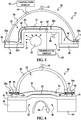
- a double vacuum chamber apparatus 20 is used to perform out-of-autoclave curing of a composite part 22.
- part and “composite part” are used in their broadest sense and include but are not limited to various forms of structures, such as, without limitation, beams, supports, panels, structural and non-structural members, elements and subassemblies, to name only a few.
- the part 22 may comprise a multi-ply prepreg laminate which is placed on or against a tool 24 supported on a metallic tool base 26.
- a substantially rigid outer shroud 28 is sealed around its outer periphery 27 to the tool base 26 by a seal 36, thereby forming a first, outer vacuum chamber 32 over the composite part 22.
- the seal 36 may comprise a reusable elastomeric seal that is permanently affixed to the periphery 27 of the outer shroud 28.
- the outer shroud 28 may comprise any suitable material such as a metal or a composite that possesses sufficient rigidity to allow the shroud 28 to be substantially self-supporting and retain its shape.
- the shroud 28 may possess any of various shapes both in footprint and cross section, that is suitable for covering the particular part 22 to be cured.
- the outer shroud 28 includes a vacuum port 50 connected with a suitable vacuum source 25 which is operable to draw a desired vacuum in the outer vacuum chamber 32.
- a flexible, inner vacuum bag 30 contained inside the outer shroud 28 also covers the part 22 and is sealed around its periphery 29 to the tool base 26, thereby forming a second, inner vacuum chamber 34 over the part 22.
- the bag 30 may comprise, for example and without limitation, a conventional one-time-use nylon bag and the seal 38 may be a conventional, non-reusable sealant.
- the bag 30 may be a reusable type made of, for example and without limitation, an elastomeric material, and the seal 38 may comprise a reusable elastomeric seal.
- additional layers of material may be placed on the part 22, beneath the flexible bag 30, including but not limited to separator films, breathers and caul plates.
- the tool base 26 may include a passageway 46 therein which communicates with the inner vacuum chamber 34.
- the passageway 46 is coupled through a vacuum port 38 to a vacuum source 35 which is used to draw a desired level of vacuum within the inner vacuum chamber 34 during cure processing.
- the tool base 26 may also include one or more vent openings 40 therein to allow heat indicated by the arrows 42 from a heat source 44 to be vented directly against the tool 24.
- cure processing using the apparatus 20 may be performed within an oven (not shown) which is used to heat the composite part 22 to the required cure temperature.
- FIG. 2 illustrates an alternate embodiment of the apparatus 20 in which a reusable type elastomeric inner vacuum bag 30 covers the composite part 20.
- the bag 30 includes a magnetic strip 52 integrated into and surrounding the periphery of the bag 30 for holding the bag 30 against the metallic tool base 26.
- the bag 30 further includes a reusable vacuum seal 54 permanently bonded to the bag 30 for creating a vacuum tight seal outside of the magnetic strip 52 and surrounding the part 22. Integration of the bag 30, the magnetic strip 52 and the reusable seal 54 into a single assembly allow the bag 30 to be quickly deployed over the part 22 and sealed to the tool base 26.
- FIG. 3 illustrates another embodiment of the apparatus 20 in which the inner, flexible bag 30 is permanently attached to the periphery 27 of the outer shroud 28 so that the outer shroud 28 and inner bag 30 form a single double vacuum chamber assembly 37 that may be easily and quickly placed on and sealed to the tool base 26, covering the part 22.
- the integration of the outer shroud 28, inner bag 30 and seal 36 into a single assembly 37 permits checking the outer shroud 28 and inner bag 30 for leaks before they are installed over the part 22, thus reducing processing time.
- a reusable seal 36 is attached to the periphery 27 of the shroud 28, with the inner bag 30 sandwiched therebetween so that the seal 36 functions to seal both the outer and inner vacuum chambers 32, 34 respectively on the tool base 26.
- the various embodiments are described in connection with producing original composite parts as part of a manufacturing process, various components of the apparatus including the double vacuum chamber assembly 37, and well as the disclosed method may be employed to rework parts or structures.
- the embodiments may be employed to cure a composite patch (not shown) and remove volatiles therefrom that is used to rework a portion of a structure such as an aircraft skin (not shown), either to improve the structure or to restore the structure to original specifications.
- the double vacuum chamber assembly 37 may be placed on and sealed to the structure, rather than to a tool base 26 as shown in the Figures.
- FIG. 4 illustrates another embodiment of the apparatus 20 in which a tool 24 mounted on a tool base 26 includes a generally U-shaped cross section forming an opening 56 on the backside 57 of the tool 24.
- the opening 56 allows warm air shown by the arrow 58 from a suitable heat source (not shown) to circulate evenly around and directly contact the backside 57 of the tool 24, thereby improving the transfer of heat to the composite part 22.
- the tool 24 includes a pair of tool surfaces 24a, 24b for heating and maintaining the shape of the part 22.
- the outer shroud 28 is provided with a peripheral flange 28a which forms a surface 39 against which the seal 36 may conform to create a vacuum tight seal around the outer vacuum chamber 32.
- thermocouples 60 may be provided in the shroud 28 and/or in the tool 24 in order to measure the temperature of the part 22.
- Suitable displays 62 may be provided to display the temperature sensed by the thermocouples 60.
- a radiant or other form of heat source 65 may be placed within the opening 56 so as to be in close proximity to and direct heat along the back side 57 of the tool 24 in order to increase the efficiency and reduce the time required for heat transfer to the part 22.
- FIG. 6 illustrates still another embodiment of the apparatus 20 in which a thermal mass 64 comprising a thermally conductive material such as, without limitation, copper or aluminum, is attached to the backside 57 of the tool 24 in order to further maximize the speed and efficiency of heat transfer to the part 22, as well as to heat the part 22 more uniformly.
- the embodiment of the apparatus 20 shown in FIG. 6 utilizes an integrated double vacuum chamber configuration, similar to that shown in FIGS. 3 and 5 .
- the outer periphery 29 of the bag 30 is bonded to the flange 28 on the shroud 28 by a layer of adhesive 66.
- the seal 36 is in turn bonded to the periphery 30 of the bag 30 by a second layer of adhesive 68.
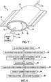
- FIG. 7 illustrates an embodiment of the apparatus 20 in which an opening 56 in the backside 57 of the tool 24 is closed by a cover 70 to form a conduit 72 through the tool 24.
- a suitable source of warm air 74 may direct warm air through the conduit 72 as shown by the arrows 76 in order to directly warm the backside 57 of the tool 24 and thus the part 22.
- the outer shroud 28 and the inner bag 30 are not shown in FIG. 7 for purposes of clarity.
- FIG. 8 illustrates the steps of a method for double vacuum curing of a composite part 22 which employs the apparatus 20 shown in FIGS. 1-7 .
- an uncured composite part 22 is placed on or against a suitable cure tool 24.
- first and second vacuums are then drawn over the part 22 using the vacuum chambers 32, 34 respectively formed by the outer shroud 28 and the inner bag 30.
- the temperature of the part 22 is continuously increased through heating until the part temperature reaches a preselected cure temperature. As will be explained below, the part temperature is increased at a constant rate.
- the first vacuum is reduced to some preselected level, as shown at step 84 so that the level of the second vacuum is greater than the level of the first vacuum.
- the cure temperature is maintained, as shown at step 86 for a preselected period during which the part 22 cures.
- the temperature of the part 22 is reduced as shown at step 88, and the first and second vacuums are terminated as shown at step 90.
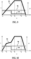
- FIG. 9 illustrates vacuum pressure and temperature profiles according to processing schedule suitable for double vacuum curing of the composite part 22.
- the disclosed method utilizing the processing schedule shown in FIG. 9 may also be used to remove volatiles and cure composite patches (not shown) used to rework an area of a part or structure.
- the temperature of the part 22 indicated by plot 92 is continuously increased at a substantially constant rate from time t 0 to t 2 until the preselected cure temperature has been reached at t 2 .
- the vacuum pressures in the outer and inner vacuum chambers 32, 34, respectively represented by plots 94 and 96 are drawn to preselected levels, the first vacuum pressure 94 in the outer vacuum chamber 32 is slightly above the vacuum pressure 96 in the inner chamber 34.
- the vacuum pressure 96 in the inner chamber 34 is maintained substantially constant during the entire process cycle. However, at some point, t 1 between t 0 and t 2 , the vacuum pressure 94 in the outer vacuum chamber 32 is reduced to a level that is materially less than the vacuum pressure 96 in the inner vacuum chamber 34. During the period between t 0 and t 1 , because the two pressures 94, 96 are nearly equal, the vacuum pressure 94 in the outer vacuum chamber 32 prevents the inner bag 30 from applying full compaction pressure on the part 22, thereby allowing volatiles in the part 22 to escape more readily as the temperature 92 is being ramped up to the cure temperature.
- the reduction of the vacuum pressure 94 allows the vacuum pressure 96 in the inner chamber 34 to apply nearly full pressure to the part 22 in order to compact the part 22 and force out air pockets in the laminate part 22 to avoid porosities.
- the period between t 2 and t 3 represents the preselected period during which the temperature 92 is maintained at a constant cure temperature. Beginning at t 3 , the temperature 92 is ramped down during a cooling cycle to an ambient temperature at t 4 , at which point the vacuum pressures 94, 96 may be terminated.
- FIG. 10 illustrates a cure processing schedule, not part of the claimed invention, which is generally similar to FIG. 9 however ramping of the temperature 92 to the cure temperature, though continuous, is not constant, but rather includes one or more changes in the rate of temperature increase.
- the temperature 92 is increased between t 0 and t 1 at a rate that is greater than that shown in the schedule of FIG. 9 .
- the rate of temperature increase is reduced until t 2 at which point the temperature ramp rate is resumed until the cure temperature is reached at t 3 .
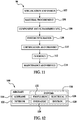
- Embodiments of the disclosure may find use in a variety of potential applications, particularly in the transportation industry, including for example, aerospace, marine and automotive applications.
- exemplary method 98 may include specification and design 102 of the aircraft 100 and material procurement 104.
- component and subassembly manufacturing 106 and system integration 108 of the aircraft 100 takes place.
- the disclosed methods and apparatus may be used to cure composite parts manufactured during step 106 and integrated in step 108.
- the aircraft 100 may go through certification and delivery 110 in order to be placed in service 112.
- routine maintenance and service 114 which may also include modification, reconfiguration, refurbishment, and so on.
- the disclosed methods and apparatus may be used to cure composite parts that are installed on the aircraft 100 during the maintenance and service 114.
- a system integrator may include without limitation any number of aircraft manufacturers and major-system subcontractors; a third party may include without limitation any number of vendors, subcontractors, and suppliers; and an operator may be an airline, leasing company, military entity, service organization, and so on.
- the aircraft 100 produced by exemplary method 98 may include an airframe 116 with a plurality of systems 118 and an interior 120.
- high-level systems 118 include one or more of a propulsion system 122, an electrical system 124, a hydraulic system 126, and an environmental system 128. Any number of other systems may be included.
- an aerospace example is shown, the principles of the disclosure may be applied to other industries, such as the marine, automotive and construction industries.
- the apparatus and methods embodied herein may be employed during any one or more of the stages of the production and service method 98.
- components or subassemblies corresponding to production process 98 may be fabricated or manufactured in a manner similar to components or subassemblies produced while the aircraft 100 is in service.
- one or more apparatus embodiments, method embodiments, or a combination thereof may be utilized during the production stages 106 and 108, for example, by substantially expediting assembly of or reducing the cost of an aircraft 100.
- apparatus embodiments, method embodiments, or a combination thereof may be utilized while the aircraft 100 is in service, for example and without limitation, to maintenance and service 114.
Landscapes
- Engineering & Computer Science (AREA)
- Mechanical Engineering (AREA)
- Chemical & Material Sciences (AREA)
- Composite Materials (AREA)
- Casting Or Compression Moulding Of Plastics Or The Like (AREA)
- Moulding By Coating Moulds (AREA)
Claims (3)
- Procédé de traitement thermique d'une pièce composite, consistant à :placer la pièce composite (22) contre un outil (24) ayant au moins un premier côté (24a) et un second côté opposé au premier côté (24a), la pièce composite étant placée contre le premier côté ;faire circuler un premier vide et un second vide au-dessus de la pièce composite (22) dans une première zone vide (34) correspondante, dans laquelle est située la pièce composite et une seconde zone vide (32) en dehors de la première zone vide, la pression à vide (94) du second vide étant légèrement au-dessus de la pression à vide (96) du premier vide ;augmenter une température de la pièce composite (22) en chauffant l'outil et la pièce composite de manière sensiblement continue à une vitesse sensiblement constante jusqu'à ce que l'outil et la pièce composite atteignent une température de traitement thermique présélectionnée ; etavant que la température atteigne une température de traitement thermique de la pièce composite, diminuer la pression à vide (94) du second vide à un niveau qui est matériellement inférieur à la pression à vide du premier vide ;maintenir la température de la pièce composite sensiblement à la température de traitement thermique pendant une durée présélectionnée tout en maintenant la pression à vide du premier vide (96) sensiblement constante pendant tout le cycle de traitement ; et
diminuer la température de la pièce composite après que la température de traitement thermique a été maintenue pendant la durée présélectionnée ;
terminer les vides dans les première et seconde chambres à vide ;
dans lequel l'étape consistant à faire circuler le premier vide et le second vide consiste à :placer un sac sensiblement flexible (30) au-dessus de la pièce composite (22) pour former la première zone vide (34),former un joint sensiblement étanche au vide entre le sac (30) et l'outil (24),faire circuler l'air provenant du sac (30) à travers un premier orifice de vide (48) dans l'outil (24),placer une enveloppe sensiblement rigide (28) au-dessus du sac et de la pièce composite (22) pour former la seconde zone vide (32), etfaire circuler l'air provenant de l'enveloppe (28) à travers un second orifice de vide (50) dans l'enveloppe (28) ;former un joint étanche au vide entre le sac (30) et l'enveloppe (28). - Procédé selon la revendication 1, consistant en outre à :retenir une périphérie du sac (30) contre l'outil en utilisant un aimant.
- Procédé de traitement thermique d'une pièce composite (22) selon la revendication claim 1, consistant à :former, sur le premier côté, une première chambre à vide extérieure (32) au-dessus de la pièce, en plaçant une enveloppe (28) au-dessus de la pièce pour définir la première zone vide ;former, sur le premier côté, une seconde chambre à vide intérieure (34) au-dessus de la pièce, en plaçant un sac (30) au-dessus de la pièce composite à l'intérieur de l'enveloppe (28) pour définir la seconde zone à vide ;former un premier joint sensiblement étanche au vide entre l'enveloppe (28) et le sac (30) ;former un second joint sensiblement étanche au vide entre l'enveloppe ((30) et l'outil (24) ;dans lequel ledit premier vide est mis en circulation dans la première chambre à vide (32) ; etdans lequel ledit second vide est mis en circulation dans la dans la seconde chambre à vide (34).
Applications Claiming Priority (2)
| Application Number | Priority Date | Filing Date | Title |
|---|---|---|---|
| US12/641,897 US20110146906A1 (en) | 2009-12-18 | 2009-12-18 | Double Vacuum Cure Processing of Composite Parts |
| PCT/US2010/056605 WO2011075252A1 (fr) | 2009-12-18 | 2010-11-12 | Procédé de traitement sous vide double de pièces composites |
Publications (2)
| Publication Number | Publication Date |
|---|---|
| EP2512783A1 EP2512783A1 (fr) | 2012-10-24 |
| EP2512783B1 true EP2512783B1 (fr) | 2017-01-04 |
Family
ID=43502953
Family Applications (1)
| Application Number | Title | Priority Date | Filing Date |
|---|---|---|---|
| EP10779651.8A Active EP2512783B1 (fr) | 2009-12-18 | 2010-11-12 | Procédé de traitement sous vide double de pièces composites |
Country Status (8)
| Country | Link |
|---|---|
| US (1) | US20110146906A1 (fr) |
| EP (1) | EP2512783B1 (fr) |
| JP (1) | JP5728493B2 (fr) |
| CN (1) | CN102712142B (fr) |
| CA (1) | CA2784378C (fr) |
| ES (1) | ES2621454T3 (fr) |
| PT (1) | PT2512783T (fr) |
| WO (1) | WO2011075252A1 (fr) |
Families Citing this family (21)
| Publication number | Priority date | Publication date | Assignee | Title |
|---|---|---|---|---|
| US8986479B2 (en) * | 2010-09-30 | 2015-03-24 | The Boeing Company | Systems and methods for on-aircraft composite repair using double vacuum debulking |
| NL2006202C2 (en) | 2011-02-15 | 2012-08-16 | Rapspice | A solar cell laminate comprising crystalline silicon photo-electricity device and process to make such a laminate. |
| US8628639B2 (en) | 2011-05-28 | 2014-01-14 | The Boeing Company | Vacuum bag processing using dual seals |
| CN102350803B (zh) * | 2011-06-24 | 2014-05-28 | 中国航空工业集团公司北京航空制造工程研究所 | 一种减少复合材料成型中真空渗漏的封装方法 |
| US20130143006A1 (en) * | 2011-12-02 | 2013-06-06 | The Boeing Company | Reducing Porosity in Composite Structures |
| CN104441699A (zh) * | 2014-12-31 | 2015-03-25 | 江苏中陆航星航空工业有限公司 | 一种可使真空袋重复利用的结构 |
| FR3039452B1 (fr) * | 2015-07-27 | 2017-12-22 | Airbus | Procede de reparation d'un panneau en materiau composite d'un aeronef et outillage pour sa mise en oeuvre |
| US10343353B2 (en) * | 2015-10-06 | 2019-07-09 | The Boeing Company | Method of curing a composite article using differential vacuum |
| US10220605B2 (en) * | 2015-11-10 | 2019-03-05 | The Boeing Company | Edge breathers for composite products |
| CN106808713A (zh) * | 2015-11-30 | 2017-06-09 | 比亚迪股份有限公司 | 一种树脂-纤维复合材料及其真空袋压成型的方法 |
| US10357922B2 (en) * | 2016-01-07 | 2019-07-23 | The Boeing Company | Edge breathers for composite products |
| US10773428B2 (en) | 2016-01-07 | 2020-09-15 | The Boeing Company | Vacuum port base |
| US10974467B2 (en) * | 2016-02-12 | 2021-04-13 | The Boeing Company | Enhanced systems that facilitate vacuum bag curing of composite parts |
| US10953575B2 (en) | 2016-02-12 | 2021-03-23 | The Boeing Company | Enhanced systems that facilitate vacuum bag curing of composite parts |
| CN106393747A (zh) * | 2016-09-21 | 2017-02-15 | 中国商用飞机有限责任公司 | 一种双真空热补仪工艺成型装置 |
| US11097524B2 (en) * | 2017-05-26 | 2021-08-24 | The Boeing Company | Flexible vacuum securement of objects to complex surfaces |
| CN110654042A (zh) * | 2018-06-29 | 2020-01-07 | 成都飞机工业(集团)有限责任公司 | 一种降低复合材料构件孔隙率的真空压实方法 |
| CN109094052B (zh) * | 2018-09-30 | 2020-11-10 | 航天特种材料及工艺技术研究所 | 一种用于热压罐成型的真空袋封装方法 |
| DE102019005912A1 (de) * | 2019-08-22 | 2021-02-25 | Siempelkamp Maschinen- Und Anlagenbau Gmbh | Verfahren und Vorrichtung zum Herstellen eines Bauteils aus einem Faserverbundwerkstoff |
| KR102148811B1 (ko) * | 2020-04-06 | 2020-08-27 | (주)아름덴티스트리 | Uv-led 경화장치 |
| EP4008534A1 (fr) * | 2020-12-03 | 2022-06-08 | LM Wind Power A/S | Méthode méthode de fabrication d'un chapeau de longeron d'une pale d'éolienne |
Citations (1)
| Publication number | Priority date | Publication date | Assignee | Title |
|---|---|---|---|---|
| US6482497B1 (en) * | 1998-11-30 | 2002-11-19 | Rocky Mountain Composites Inc. | Pressure-cycled, packet-transfer infusion of resin-stitched preforms |
Family Cites Families (26)
| Publication number | Priority date | Publication date | Assignee | Title |
|---|---|---|---|---|
| US4357193A (en) * | 1979-05-21 | 1982-11-02 | Rockwell International Corporation | Method of fabricating a composite structure |
| GB2124130B (en) * | 1982-07-24 | 1985-11-27 | Rolls Royce | Vacuum moulding fibre reinforced resin |
| US4822651A (en) * | 1985-08-30 | 1989-04-18 | Newsom Cosby M | Vacuum diaphragm device |
| US5087193A (en) * | 1990-08-09 | 1992-02-11 | Herbert Jr Kenneth H | Apparatus for forming a composite article |
| US5236646A (en) * | 1991-02-28 | 1993-08-17 | The United States Of America As Represented By The Secretary Of The Navy | Process for preparing thermoplastic composites |
| US5665301A (en) * | 1995-07-11 | 1997-09-09 | Arctek Inc. | Apparatus and method for forming fiber reinforced composite articles |
| US6017484A (en) * | 1997-01-21 | 2000-01-25 | Harold P. Hale | Method for manufacture of minimum porosity, wrinkle free composite parts |
| US6299819B1 (en) * | 1998-07-27 | 2001-10-09 | The University Of Dayton | Double-chamber vacuum resin transfer molding |
| US7413694B2 (en) * | 1999-12-07 | 2008-08-19 | The Boeing Company | Double bag vacuum infusion process |
| US6761783B2 (en) * | 2002-04-09 | 2004-07-13 | The Boeing Company | Process method to repair bismaleimide (BMI) composite structures |
| US7334782B2 (en) * | 2002-05-29 | 2008-02-26 | The Boeing Company | Controlled atmospheric pressure resin infusion process |
| DE102004021337B4 (de) * | 2004-04-30 | 2009-12-03 | Webasto Ag | Verfahren zur Herstellung eines Verbund-Karosserieteils für ein Fahrzeug |
| US7186367B2 (en) * | 2004-05-13 | 2007-03-06 | The United States Of America As Represented By The Administrator Of The National Aeronautics And Space Administration | Double vacuum bag process for resin matrix composite manufacturing |
| US20050281980A1 (en) * | 2004-06-22 | 2005-12-22 | Cruz Jose A | Vacuum pressure bag for use with large scale composite structures |
| US8052831B2 (en) * | 2005-02-02 | 2011-11-08 | The Boeing Company | Low temperature, vacuum cure fabrication process for large, honeycomb core stiffened composite structures |
| JP2006334912A (ja) * | 2005-06-01 | 2006-12-14 | Dainippon Printing Co Ltd | ラミネート装置 |
| US20070296126A1 (en) * | 2006-06-21 | 2007-12-27 | Audette Lawrence F | Reusable silicone vacuum bag/tool flange sealing method |
| GB0613872D0 (en) * | 2006-07-12 | 2006-08-23 | Airbus Uk Ltd | Method of manufacturing composite part |
| US7862679B2 (en) * | 2006-08-09 | 2011-01-04 | The Boeing Company | Integral double bag for vacuum bagging a composite part and method of using the same |
| JP5271486B2 (ja) * | 2006-08-16 | 2013-08-21 | 株式会社ブリヂストン | 離型剤、これを用いた凹凸パターンの形成方法及び光情報記録媒体の製造方法、並びに光情報記録媒体 |
| US20080083493A1 (en) * | 2006-10-10 | 2008-04-10 | Ridges Michael D | Reusable mechanical fastener and vacuum seal combination |
| US7849729B2 (en) * | 2006-12-22 | 2010-12-14 | The Boeing Company | Leak detection in vacuum bags |
| US7857925B2 (en) * | 2007-06-15 | 2010-12-28 | The Boeing Company | Process development protocol and vacuum bag process for carbon-epoxy prepreg |
| US8105068B2 (en) * | 2008-11-05 | 2012-01-31 | Spirit Aerosystems, Inc. | Reusable infusion bag |
| US20100308515A1 (en) * | 2009-06-05 | 2010-12-09 | Astoria Industries Of Iowa, Inc. | Apparatus and process for manufacturing a vacuum molded fiberglass chipper body |
| US8628639B2 (en) * | 2011-05-28 | 2014-01-14 | The Boeing Company | Vacuum bag processing using dual seals |
-
2009
- 2009-12-18 US US12/641,897 patent/US20110146906A1/en not_active Abandoned
-
2010
- 2010-11-12 EP EP10779651.8A patent/EP2512783B1/fr active Active
- 2010-11-12 WO PCT/US2010/056605 patent/WO2011075252A1/fr active Application Filing
- 2010-11-12 CA CA2784378A patent/CA2784378C/fr active Active
- 2010-11-12 JP JP2012544528A patent/JP5728493B2/ja active Active
- 2010-11-12 CN CN201080057416.7A patent/CN102712142B/zh active Active
- 2010-11-12 PT PT107796518T patent/PT2512783T/pt unknown
- 2010-11-12 ES ES10779651.8T patent/ES2621454T3/es active Active
Patent Citations (1)
| Publication number | Priority date | Publication date | Assignee | Title |
|---|---|---|---|---|
| US6482497B1 (en) * | 1998-11-30 | 2002-11-19 | Rocky Mountain Composites Inc. | Pressure-cycled, packet-transfer infusion of resin-stitched preforms |
Also Published As
| Publication number | Publication date |
|---|---|
| CN102712142A (zh) | 2012-10-03 |
| ES2621454T3 (es) | 2017-07-04 |
| WO2011075252A1 (fr) | 2011-06-23 |
| CA2784378A1 (fr) | 2011-06-23 |
| CA2784378C (fr) | 2019-01-08 |
| EP2512783A1 (fr) | 2012-10-24 |
| PT2512783T (pt) | 2017-02-01 |
| JP5728493B2 (ja) | 2015-06-03 |
| CN102712142B (zh) | 2015-12-16 |
| JP2013514209A (ja) | 2013-04-25 |
| US20110146906A1 (en) | 2011-06-23 |
Similar Documents
| Publication | Publication Date | Title |
|---|---|---|
| EP2512783B1 (fr) | Procédé de traitement sous vide double de pièces composites | |
| EP2529919B1 (fr) | Traitement de sacs sous vide au moyen de joints doubles | |
| US8444127B2 (en) | High temperature composite patch tool | |
| JP6659749B2 (ja) | 真空の完全性を有する複合ツール及びその製造方法 | |
| EP2565005B1 (fr) | Sac sous vide réutilisable et intégralement renforcé et son procédé de fabrication | |
| EP2671709B1 (fr) | Système de vessie sans reprise d'air pour le durcissement de pièces composites | |
| US11400620B2 (en) | Methods and apparatus for curing composite nacelle structure | |
| US7842209B2 (en) | Vacuum debulk and radiation cure method | |
| EP2632723B1 (fr) | Procédé en une seule étape d'application de pression pour faire diminuer le volume et de durcissement d'un matériau préimprégné | |
| US11904560B2 (en) | Vacuum bag-less composite repair systems and methods | |
| US9862154B2 (en) | Apparatuses and methods for efficient sealing of vacuum bag seams | |
| US7662334B2 (en) | Vacuum heat-set of net shape latex vacuum bags | |
| US6991449B1 (en) | Heating apparatus for in-situ de-bulking composite parts during layup | |
| US6565690B1 (en) | Process for manufacturing structures of composite material | |
| CN114536813A (zh) | 用于处理复合结构的设备和方法 | |
| CN114536803A (zh) | 用于处理复合结构的设备和方法 |
Legal Events
| Date | Code | Title | Description |
|---|---|---|---|
| PUAI | Public reference made under article 153(3) epc to a published international application that has entered the european phase |
Free format text: ORIGINAL CODE: 0009012 |
|
| 17P | Request for examination filed |
Effective date: 20120718 |
|
| AK | Designated contracting states |
Kind code of ref document: A1 Designated state(s): AL AT BE BG CH CY CZ DE DK EE ES FI FR GB GR HR HU IE IS IT LI LT LU LV MC MK MT NL NO PL PT RO RS SE SI SK SM TR |
|
| DAX | Request for extension of the european patent (deleted) | ||
| 17Q | First examination report despatched |
Effective date: 20130429 |
|
| GRAP | Despatch of communication of intention to grant a patent |
Free format text: ORIGINAL CODE: EPIDOSNIGR1 |
|
| INTG | Intention to grant announced |
Effective date: 20160609 |
|
| GRAS | Grant fee paid |
Free format text: ORIGINAL CODE: EPIDOSNIGR3 |
|
| GRAA | (expected) grant |
Free format text: ORIGINAL CODE: 0009210 |
|
| AK | Designated contracting states |
Kind code of ref document: B1 Designated state(s): AL AT BE BG CH CY CZ DE DK EE ES FI FR GB GR HR HU IE IS IT LI LT LU LV MC MK MT NL NO PL PT RO RS SE SI SK SM TR |
|
| REG | Reference to a national code |
Ref country code: GB Ref legal event code: FG4D |
|
| REG | Reference to a national code |
Ref country code: CH Ref legal event code: EP |
|
| REG | Reference to a national code |
Ref country code: AT Ref legal event code: REF Ref document number: 858812 Country of ref document: AT Kind code of ref document: T Effective date: 20170115 |
|
| REG | Reference to a national code |
Ref country code: IE Ref legal event code: FG4D |
|
| REG | Reference to a national code |
Ref country code: PT Ref legal event code: SC4A Ref document number: 2512783 Country of ref document: PT Date of ref document: 20170201 Kind code of ref document: T Free format text: AVAILABILITY OF NATIONAL TRANSLATION Effective date: 20170120 |
|
| REG | Reference to a national code |
Ref country code: DE Ref legal event code: R096 Ref document number: 602010039356 Country of ref document: DE |
|
| REG | Reference to a national code |
Ref country code: SE Ref legal event code: TRGR |
|
| REG | Reference to a national code |
Ref country code: LT Ref legal event code: MG4D Ref country code: NL Ref legal event code: MP Effective date: 20170104 |
|
| REG | Reference to a national code |
Ref country code: AT Ref legal event code: MK05 Ref document number: 858812 Country of ref document: AT Kind code of ref document: T Effective date: 20170104 |
|
| PG25 | Lapsed in a contracting state [announced via postgrant information from national office to epo] |
Ref country code: NL Free format text: LAPSE BECAUSE OF FAILURE TO SUBMIT A TRANSLATION OF THE DESCRIPTION OR TO PAY THE FEE WITHIN THE PRESCRIBED TIME-LIMIT Effective date: 20170104 |
|
| REG | Reference to a national code |
Ref country code: ES Ref legal event code: FG2A Ref document number: 2621454 Country of ref document: ES Kind code of ref document: T3 Effective date: 20170704 |
|
| PG25 | Lapsed in a contracting state [announced via postgrant information from national office to epo] |
Ref country code: IS Free format text: LAPSE BECAUSE OF FAILURE TO SUBMIT A TRANSLATION OF THE DESCRIPTION OR TO PAY THE FEE WITHIN THE PRESCRIBED TIME-LIMIT Effective date: 20170504 Ref country code: GR Free format text: LAPSE BECAUSE OF FAILURE TO SUBMIT A TRANSLATION OF THE DESCRIPTION OR TO PAY THE FEE WITHIN THE PRESCRIBED TIME-LIMIT Effective date: 20170405 Ref country code: FI Free format text: LAPSE BECAUSE OF FAILURE TO SUBMIT A TRANSLATION OF THE DESCRIPTION OR TO PAY THE FEE WITHIN THE PRESCRIBED TIME-LIMIT Effective date: 20170104 Ref country code: NO Free format text: LAPSE BECAUSE OF FAILURE TO SUBMIT A TRANSLATION OF THE DESCRIPTION OR TO PAY THE FEE WITHIN THE PRESCRIBED TIME-LIMIT Effective date: 20170404 Ref country code: LT Free format text: LAPSE BECAUSE OF FAILURE TO SUBMIT A TRANSLATION OF THE DESCRIPTION OR TO PAY THE FEE WITHIN THE PRESCRIBED TIME-LIMIT Effective date: 20170104 Ref country code: HR Free format text: LAPSE BECAUSE OF FAILURE TO SUBMIT A TRANSLATION OF THE DESCRIPTION OR TO PAY THE FEE WITHIN THE PRESCRIBED TIME-LIMIT Effective date: 20170104 |
|
| PG25 | Lapsed in a contracting state [announced via postgrant information from national office to epo] |
Ref country code: AT Free format text: LAPSE BECAUSE OF FAILURE TO SUBMIT A TRANSLATION OF THE DESCRIPTION OR TO PAY THE FEE WITHIN THE PRESCRIBED TIME-LIMIT Effective date: 20170104 Ref country code: PL Free format text: LAPSE BECAUSE OF FAILURE TO SUBMIT A TRANSLATION OF THE DESCRIPTION OR TO PAY THE FEE WITHIN THE PRESCRIBED TIME-LIMIT Effective date: 20170104 Ref country code: RS Free format text: LAPSE BECAUSE OF FAILURE TO SUBMIT A TRANSLATION OF THE DESCRIPTION OR TO PAY THE FEE WITHIN THE PRESCRIBED TIME-LIMIT Effective date: 20170104 Ref country code: LV Free format text: LAPSE BECAUSE OF FAILURE TO SUBMIT A TRANSLATION OF THE DESCRIPTION OR TO PAY THE FEE WITHIN THE PRESCRIBED TIME-LIMIT Effective date: 20170104 Ref country code: BG Free format text: LAPSE BECAUSE OF FAILURE TO SUBMIT A TRANSLATION OF THE DESCRIPTION OR TO PAY THE FEE WITHIN THE PRESCRIBED TIME-LIMIT Effective date: 20170404 |
|
| REG | Reference to a national code |
Ref country code: DE Ref legal event code: R097 Ref document number: 602010039356 Country of ref document: DE |
|
| PG25 | Lapsed in a contracting state [announced via postgrant information from national office to epo] |
Ref country code: RO Free format text: LAPSE BECAUSE OF FAILURE TO SUBMIT A TRANSLATION OF THE DESCRIPTION OR TO PAY THE FEE WITHIN THE PRESCRIBED TIME-LIMIT Effective date: 20170104 Ref country code: EE Free format text: LAPSE BECAUSE OF FAILURE TO SUBMIT A TRANSLATION OF THE DESCRIPTION OR TO PAY THE FEE WITHIN THE PRESCRIBED TIME-LIMIT Effective date: 20170104 Ref country code: CZ Free format text: LAPSE BECAUSE OF FAILURE TO SUBMIT A TRANSLATION OF THE DESCRIPTION OR TO PAY THE FEE WITHIN THE PRESCRIBED TIME-LIMIT Effective date: 20170104 Ref country code: SK Free format text: LAPSE BECAUSE OF FAILURE TO SUBMIT A TRANSLATION OF THE DESCRIPTION OR TO PAY THE FEE WITHIN THE PRESCRIBED TIME-LIMIT Effective date: 20170104 |
|
| PLBE | No opposition filed within time limit |
Free format text: ORIGINAL CODE: 0009261 |
|
| STAA | Information on the status of an ep patent application or granted ep patent |
Free format text: STATUS: NO OPPOSITION FILED WITHIN TIME LIMIT |
|
| REG | Reference to a national code |
Ref country code: FR Ref legal event code: PLFP Year of fee payment: 8 |
|
| PG25 | Lapsed in a contracting state [announced via postgrant information from national office to epo] |
Ref country code: SM Free format text: LAPSE BECAUSE OF FAILURE TO SUBMIT A TRANSLATION OF THE DESCRIPTION OR TO PAY THE FEE WITHIN THE PRESCRIBED TIME-LIMIT Effective date: 20170104 Ref country code: DK Free format text: LAPSE BECAUSE OF FAILURE TO SUBMIT A TRANSLATION OF THE DESCRIPTION OR TO PAY THE FEE WITHIN THE PRESCRIBED TIME-LIMIT Effective date: 20170104 |
|
| 26N | No opposition filed |
Effective date: 20171005 |
|
| PG25 | Lapsed in a contracting state [announced via postgrant information from national office to epo] |
Ref country code: SI Free format text: LAPSE BECAUSE OF FAILURE TO SUBMIT A TRANSLATION OF THE DESCRIPTION OR TO PAY THE FEE WITHIN THE PRESCRIBED TIME-LIMIT Effective date: 20170104 |
|
| PG25 | Lapsed in a contracting state [announced via postgrant information from national office to epo] |
Ref country code: MC Free format text: LAPSE BECAUSE OF FAILURE TO SUBMIT A TRANSLATION OF THE DESCRIPTION OR TO PAY THE FEE WITHIN THE PRESCRIBED TIME-LIMIT Effective date: 20170104 |
|
| PG25 | Lapsed in a contracting state [announced via postgrant information from national office to epo] |
Ref country code: CH Free format text: LAPSE BECAUSE OF NON-PAYMENT OF DUE FEES Effective date: 20171130 Ref country code: LI Free format text: LAPSE BECAUSE OF NON-PAYMENT OF DUE FEES Effective date: 20171130 |
|
| PG25 | Lapsed in a contracting state [announced via postgrant information from national office to epo] |
Ref country code: LU Free format text: LAPSE BECAUSE OF NON-PAYMENT OF DUE FEES Effective date: 20171112 |
|
| REG | Reference to a national code |
Ref country code: BE Ref legal event code: MM Effective date: 20171130 |
|
| REG | Reference to a national code |
Ref country code: IE Ref legal event code: MM4A |
|
| PG25 | Lapsed in a contracting state [announced via postgrant information from national office to epo] |
Ref country code: MT Free format text: LAPSE BECAUSE OF NON-PAYMENT OF DUE FEES Effective date: 20171112 |
|
| PG25 | Lapsed in a contracting state [announced via postgrant information from national office to epo] |
Ref country code: IE Free format text: LAPSE BECAUSE OF NON-PAYMENT OF DUE FEES Effective date: 20171112 |
|
| PG25 | Lapsed in a contracting state [announced via postgrant information from national office to epo] |
Ref country code: BE Free format text: LAPSE BECAUSE OF NON-PAYMENT OF DUE FEES Effective date: 20171130 |
|
| PG25 | Lapsed in a contracting state [announced via postgrant information from national office to epo] |
Ref country code: HU Free format text: LAPSE BECAUSE OF FAILURE TO SUBMIT A TRANSLATION OF THE DESCRIPTION OR TO PAY THE FEE WITHIN THE PRESCRIBED TIME-LIMIT; INVALID AB INITIO Effective date: 20101112 |
|
| PG25 | Lapsed in a contracting state [announced via postgrant information from national office to epo] |
Ref country code: CY Free format text: LAPSE BECAUSE OF NON-PAYMENT OF DUE FEES Effective date: 20170104 |
|
| PG25 | Lapsed in a contracting state [announced via postgrant information from national office to epo] |
Ref country code: MK Free format text: LAPSE BECAUSE OF FAILURE TO SUBMIT A TRANSLATION OF THE DESCRIPTION OR TO PAY THE FEE WITHIN THE PRESCRIBED TIME-LIMIT Effective date: 20170104 |
|
| PG25 | Lapsed in a contracting state [announced via postgrant information from national office to epo] |
Ref country code: TR Free format text: LAPSE BECAUSE OF FAILURE TO SUBMIT A TRANSLATION OF THE DESCRIPTION OR TO PAY THE FEE WITHIN THE PRESCRIBED TIME-LIMIT Effective date: 20170104 |
|
| PG25 | Lapsed in a contracting state [announced via postgrant information from national office to epo] |
Ref country code: AL Free format text: LAPSE BECAUSE OF FAILURE TO SUBMIT A TRANSLATION OF THE DESCRIPTION OR TO PAY THE FEE WITHIN THE PRESCRIBED TIME-LIMIT Effective date: 20170104 |
|
| REG | Reference to a national code |
Ref country code: DE Ref legal event code: R082 Ref document number: 602010039356 Country of ref document: DE Representative=s name: KILBURN & STRODE LLP, NL |
|
| P01 | Opt-out of the competence of the unified patent court (upc) registered |
Effective date: 20230516 |
|
| PGFP | Annual fee paid to national office [announced via postgrant information from national office to epo] |
Ref country code: GB Payment date: 20231127 Year of fee payment: 14 |
|
| PGFP | Annual fee paid to national office [announced via postgrant information from national office to epo] |
Ref country code: ES Payment date: 20231201 Year of fee payment: 14 |
|
| PGFP | Annual fee paid to national office [announced via postgrant information from national office to epo] |
Ref country code: SE Payment date: 20231127 Year of fee payment: 14 Ref country code: PT Payment date: 20231024 Year of fee payment: 14 Ref country code: IT Payment date: 20231122 Year of fee payment: 14 Ref country code: FR Payment date: 20231127 Year of fee payment: 14 Ref country code: DE Payment date: 20231129 Year of fee payment: 14 |