EP2512783B1 - Double vacuum cure processing of composite parts - Google Patents
Double vacuum cure processing of composite parts Download PDFInfo
- Publication number
- EP2512783B1 EP2512783B1 EP10779651.8A EP10779651A EP2512783B1 EP 2512783 B1 EP2512783 B1 EP 2512783B1 EP 10779651 A EP10779651 A EP 10779651A EP 2512783 B1 EP2512783 B1 EP 2512783B1
- Authority
- EP
- European Patent Office
- Prior art keywords
- vacuum
- composite part
- bag
- tool
- temperature
- Prior art date
- Legal status (The legal status is an assumption and is not a legal conclusion. Google has not performed a legal analysis and makes no representation as to the accuracy of the status listed.)
- Active
Links
- 239000002131 composite material Substances 0.000 title claims description 46
- 238000012545 processing Methods 0.000 title description 22
- 238000000034 method Methods 0.000 claims description 32
- 238000010438 heat treatment Methods 0.000 claims description 7
- 230000008569 process Effects 0.000 claims description 7
- 238000004519 manufacturing process Methods 0.000 description 11
- 239000003039 volatile agent Substances 0.000 description 5
- 238000012546 transfer Methods 0.000 description 4
- 238000010586 diagram Methods 0.000 description 3
- 230000010354 integration Effects 0.000 description 3
- 238000012423 maintenance Methods 0.000 description 3
- 239000000463 material Substances 0.000 description 3
- 239000000853 adhesive Substances 0.000 description 2
- 230000001070 adhesive effect Effects 0.000 description 2
- 230000001747 exhibiting effect Effects 0.000 description 2
- 230000009467 reduction Effects 0.000 description 2
- 239000011347 resin Substances 0.000 description 2
- 229920005989 resin Polymers 0.000 description 2
- RYGMFSIKBFXOCR-UHFFFAOYSA-N Copper Chemical compound [Cu] RYGMFSIKBFXOCR-UHFFFAOYSA-N 0.000 description 1
- 239000004677 Nylon Substances 0.000 description 1
- 229910052782 aluminium Inorganic materials 0.000 description 1
- XAGFODPZIPBFFR-UHFFFAOYSA-N aluminium Chemical compound [Al] XAGFODPZIPBFFR-UHFFFAOYSA-N 0.000 description 1
- 238000006243 chemical reaction Methods 0.000 description 1
- 238000005056 compaction Methods 0.000 description 1
- 239000004020 conductor Substances 0.000 description 1
- 238000010276 construction Methods 0.000 description 1
- 238000001816 cooling Methods 0.000 description 1
- 229910052802 copper Inorganic materials 0.000 description 1
- 239000010949 copper Substances 0.000 description 1
- 238000013461 design Methods 0.000 description 1
- 239000013536 elastomeric material Substances 0.000 description 1
- 230000008030 elimination Effects 0.000 description 1
- 238000003379 elimination reaction Methods 0.000 description 1
- 230000007613 environmental effect Effects 0.000 description 1
- 210000000569 greater omentum Anatomy 0.000 description 1
- 239000011159 matrix material Substances 0.000 description 1
- 229910052751 metal Inorganic materials 0.000 description 1
- 239000002184 metal Substances 0.000 description 1
- 238000012986 modification Methods 0.000 description 1
- 230000004048 modification Effects 0.000 description 1
- 229920001778 nylon Polymers 0.000 description 1
- 230000008520 organization Effects 0.000 description 1
- 230000002093 peripheral effect Effects 0.000 description 1
- 238000003672 processing method Methods 0.000 description 1
- 238000009419 refurbishment Methods 0.000 description 1
- 239000000565 sealant Substances 0.000 description 1
- -1 without limitation Substances 0.000 description 1
Images


Classifications
-
- B—PERFORMING OPERATIONS; TRANSPORTING
- B29—WORKING OF PLASTICS; WORKING OF SUBSTANCES IN A PLASTIC STATE IN GENERAL
- B29C—SHAPING OR JOINING OF PLASTICS; SHAPING OF MATERIAL IN A PLASTIC STATE, NOT OTHERWISE PROVIDED FOR; AFTER-TREATMENT OF THE SHAPED PRODUCTS, e.g. REPAIRING
- B29C70/00—Shaping composites, i.e. plastics material comprising reinforcements, fillers or preformed parts, e.g. inserts
- B29C70/04—Shaping composites, i.e. plastics material comprising reinforcements, fillers or preformed parts, e.g. inserts comprising reinforcements only, e.g. self-reinforcing plastics
- B29C70/28—Shaping operations therefor
- B29C70/40—Shaping or impregnating by compression not applied
- B29C70/42—Shaping or impregnating by compression not applied for producing articles of definite length, i.e. discrete articles
- B29C70/44—Shaping or impregnating by compression not applied for producing articles of definite length, i.e. discrete articles using isostatic pressure, e.g. pressure difference-moulding, vacuum bag-moulding, autoclave-moulding or expanding rubber-moulding
-
- B—PERFORMING OPERATIONS; TRANSPORTING
- B29—WORKING OF PLASTICS; WORKING OF SUBSTANCES IN A PLASTIC STATE IN GENERAL
- B29C—SHAPING OR JOINING OF PLASTICS; SHAPING OF MATERIAL IN A PLASTIC STATE, NOT OTHERWISE PROVIDED FOR; AFTER-TREATMENT OF THE SHAPED PRODUCTS, e.g. REPAIRING
- B29C37/00—Component parts, details, accessories or auxiliary operations, not covered by group B29C33/00 or B29C35/00
- B29C37/006—Degassing moulding material or draining off gas during moulding
-
- B—PERFORMING OPERATIONS; TRANSPORTING
- B29—WORKING OF PLASTICS; WORKING OF SUBSTANCES IN A PLASTIC STATE IN GENERAL
- B29C—SHAPING OR JOINING OF PLASTICS; SHAPING OF MATERIAL IN A PLASTIC STATE, NOT OTHERWISE PROVIDED FOR; AFTER-TREATMENT OF THE SHAPED PRODUCTS, e.g. REPAIRING
- B29C73/00—Repairing of articles made from plastics or substances in a plastic state, e.g. of articles shaped or produced by using techniques covered by this subclass or subclass B29D
- B29C73/04—Repairing of articles made from plastics or substances in a plastic state, e.g. of articles shaped or produced by using techniques covered by this subclass or subclass B29D using preformed elements
- B29C73/10—Repairing of articles made from plastics or substances in a plastic state, e.g. of articles shaped or produced by using techniques covered by this subclass or subclass B29D using preformed elements using patches sealing on the surface of the article
-
- B—PERFORMING OPERATIONS; TRANSPORTING
- B29—WORKING OF PLASTICS; WORKING OF SUBSTANCES IN A PLASTIC STATE IN GENERAL
- B29C—SHAPING OR JOINING OF PLASTICS; SHAPING OF MATERIAL IN A PLASTIC STATE, NOT OTHERWISE PROVIDED FOR; AFTER-TREATMENT OF THE SHAPED PRODUCTS, e.g. REPAIRING
- B29C73/00—Repairing of articles made from plastics or substances in a plastic state, e.g. of articles shaped or produced by using techniques covered by this subclass or subclass B29D
- B29C73/24—Apparatus or accessories not otherwise provided for
- B29C73/30—Apparatus or accessories not otherwise provided for for local pressing or local heating
Definitions
- This disclosure generally relates to equipment and methods for making composite parts, and deals more particularly with double vacuum cure processing of composites.
- Autoclaves are widely used to cure composite parts having higher performance specifications requiring tight dimensional tolerances and low porosity. Heating the composite within an autoclave results in a chemical reaction that both cures the resin and produces volatiles inside the composite that are driven out by pressure applied to the atmosphere within the autoclave.
- pressclaves may be used to cure composites by applying heat and pressure to a heated part through an inflatable bladder. Autoclaves, pressclaves and similar equipment may be undesirable for use in some applications, however, due to their higher capital cost and the labor they require for setup and operation.
- autoclave and pressclave cure processing may be limited by the size of parts that can be processed.
- Double vacuum bag (DVB) processing may also be employed to cure composite parts such as prepreg laminates. Unlike autoclave curing, DVB processing is not limited by the size of the part. The DVB process is also less capital equipment intensive than autoclave processing, and may provide tighter dimensional control and higher mechanical performance in the cured part compared to autoclave processing or single vacuum bag (SVB) processing.
- SVB single vacuum bag
- DVB equipment comprises inner and outer vacuum bags that must be individually positioned and sealed to a tool base using hand labor. The bags must each be leak checked before processing begins. Additionally, the current DVB processing technique requires an intermediate low temperature hold step during the processing cycle in which the temperature of the part is held at a substantially constant level for a period of time as the part is ramped up to a desired cure temperature. This intermediate low temperature hold adds to the overall processing time of the part.
- the disclosed embodiments provide apparatus and a related method for curing a prepreg laminate using double vacuum processing.
- the apparatus is effective in removing volatiles, and may produce parts exhibiting reduced dimensional tolerance variations and improved mechanical properties. Time and labor needed to set up equipment and cure parts may be reduced through the use of an integrated double vacuum chamber assembly comprising a flexible inner bag that is permanently attached to a substantially rigid outer shroud. Use of the apparatus may allow reduction or elimination of an intermediate low temperature hold as the temperature of the part is being increased to the cure temperature, thereby further reducing processing time.
- the method and apparatus may be used to produce composite parts during an original manufacturing process or to rework parts using composite patches.
- the disclosed embodiments provide apparatus and a related method for double vacuum curing of composite laminates which obviate the need for autoclave processing, and may produce parts exhibiting reduced part-to-part dimensional variations and improved mechanical properties.
- a double vacuum chamber apparatus 20 is used to perform out-of-autoclave curing of a composite part 22.
- part and “composite part” are used in their broadest sense and include but are not limited to various forms of structures, such as, without limitation, beams, supports, panels, structural and non-structural members, elements and subassemblies, to name only a few.
- the part 22 may comprise a multi-ply prepreg laminate which is placed on or against a tool 24 supported on a metallic tool base 26.
- a substantially rigid outer shroud 28 is sealed around its outer periphery 27 to the tool base 26 by a seal 36, thereby forming a first, outer vacuum chamber 32 over the composite part 22.
- the seal 36 may comprise a reusable elastomeric seal that is permanently affixed to the periphery 27 of the outer shroud 28.
- the outer shroud 28 may comprise any suitable material such as a metal or a composite that possesses sufficient rigidity to allow the shroud 28 to be substantially self-supporting and retain its shape.
- the shroud 28 may possess any of various shapes both in footprint and cross section, that is suitable for covering the particular part 22 to be cured.
- the outer shroud 28 includes a vacuum port 50 connected with a suitable vacuum source 25 which is operable to draw a desired vacuum in the outer vacuum chamber 32.
- a flexible, inner vacuum bag 30 contained inside the outer shroud 28 also covers the part 22 and is sealed around its periphery 29 to the tool base 26, thereby forming a second, inner vacuum chamber 34 over the part 22.
- the bag 30 may comprise, for example and without limitation, a conventional one-time-use nylon bag and the seal 38 may be a conventional, non-reusable sealant.
- the bag 30 may be a reusable type made of, for example and without limitation, an elastomeric material, and the seal 38 may comprise a reusable elastomeric seal.
- additional layers of material may be placed on the part 22, beneath the flexible bag 30, including but not limited to separator films, breathers and caul plates.
- the tool base 26 may include a passageway 46 therein which communicates with the inner vacuum chamber 34.
- the passageway 46 is coupled through a vacuum port 38 to a vacuum source 35 which is used to draw a desired level of vacuum within the inner vacuum chamber 34 during cure processing.
- the tool base 26 may also include one or more vent openings 40 therein to allow heat indicated by the arrows 42 from a heat source 44 to be vented directly against the tool 24.
- cure processing using the apparatus 20 may be performed within an oven (not shown) which is used to heat the composite part 22 to the required cure temperature.
- FIG. 2 illustrates an alternate embodiment of the apparatus 20 in which a reusable type elastomeric inner vacuum bag 30 covers the composite part 20.
- the bag 30 includes a magnetic strip 52 integrated into and surrounding the periphery of the bag 30 for holding the bag 30 against the metallic tool base 26.
- the bag 30 further includes a reusable vacuum seal 54 permanently bonded to the bag 30 for creating a vacuum tight seal outside of the magnetic strip 52 and surrounding the part 22. Integration of the bag 30, the magnetic strip 52 and the reusable seal 54 into a single assembly allow the bag 30 to be quickly deployed over the part 22 and sealed to the tool base 26.
- FIG. 3 illustrates another embodiment of the apparatus 20 in which the inner, flexible bag 30 is permanently attached to the periphery 27 of the outer shroud 28 so that the outer shroud 28 and inner bag 30 form a single double vacuum chamber assembly 37 that may be easily and quickly placed on and sealed to the tool base 26, covering the part 22.
- the integration of the outer shroud 28, inner bag 30 and seal 36 into a single assembly 37 permits checking the outer shroud 28 and inner bag 30 for leaks before they are installed over the part 22, thus reducing processing time.
- a reusable seal 36 is attached to the periphery 27 of the shroud 28, with the inner bag 30 sandwiched therebetween so that the seal 36 functions to seal both the outer and inner vacuum chambers 32, 34 respectively on the tool base 26.
- the various embodiments are described in connection with producing original composite parts as part of a manufacturing process, various components of the apparatus including the double vacuum chamber assembly 37, and well as the disclosed method may be employed to rework parts or structures.
- the embodiments may be employed to cure a composite patch (not shown) and remove volatiles therefrom that is used to rework a portion of a structure such as an aircraft skin (not shown), either to improve the structure or to restore the structure to original specifications.
- the double vacuum chamber assembly 37 may be placed on and sealed to the structure, rather than to a tool base 26 as shown in the Figures.
- FIG. 4 illustrates another embodiment of the apparatus 20 in which a tool 24 mounted on a tool base 26 includes a generally U-shaped cross section forming an opening 56 on the backside 57 of the tool 24.
- the opening 56 allows warm air shown by the arrow 58 from a suitable heat source (not shown) to circulate evenly around and directly contact the backside 57 of the tool 24, thereby improving the transfer of heat to the composite part 22.
- the tool 24 includes a pair of tool surfaces 24a, 24b for heating and maintaining the shape of the part 22.
- the outer shroud 28 is provided with a peripheral flange 28a which forms a surface 39 against which the seal 36 may conform to create a vacuum tight seal around the outer vacuum chamber 32.
- thermocouples 60 may be provided in the shroud 28 and/or in the tool 24 in order to measure the temperature of the part 22.
- Suitable displays 62 may be provided to display the temperature sensed by the thermocouples 60.
- a radiant or other form of heat source 65 may be placed within the opening 56 so as to be in close proximity to and direct heat along the back side 57 of the tool 24 in order to increase the efficiency and reduce the time required for heat transfer to the part 22.
- FIG. 6 illustrates still another embodiment of the apparatus 20 in which a thermal mass 64 comprising a thermally conductive material such as, without limitation, copper or aluminum, is attached to the backside 57 of the tool 24 in order to further maximize the speed and efficiency of heat transfer to the part 22, as well as to heat the part 22 more uniformly.
- the embodiment of the apparatus 20 shown in FIG. 6 utilizes an integrated double vacuum chamber configuration, similar to that shown in FIGS. 3 and 5 .
- the outer periphery 29 of the bag 30 is bonded to the flange 28 on the shroud 28 by a layer of adhesive 66.
- the seal 36 is in turn bonded to the periphery 30 of the bag 30 by a second layer of adhesive 68.
- FIG. 7 illustrates an embodiment of the apparatus 20 in which an opening 56 in the backside 57 of the tool 24 is closed by a cover 70 to form a conduit 72 through the tool 24.
- a suitable source of warm air 74 may direct warm air through the conduit 72 as shown by the arrows 76 in order to directly warm the backside 57 of the tool 24 and thus the part 22.
- the outer shroud 28 and the inner bag 30 are not shown in FIG. 7 for purposes of clarity.
- FIG. 8 illustrates the steps of a method for double vacuum curing of a composite part 22 which employs the apparatus 20 shown in FIGS. 1-7 .
- an uncured composite part 22 is placed on or against a suitable cure tool 24.
- first and second vacuums are then drawn over the part 22 using the vacuum chambers 32, 34 respectively formed by the outer shroud 28 and the inner bag 30.
- the temperature of the part 22 is continuously increased through heating until the part temperature reaches a preselected cure temperature. As will be explained below, the part temperature is increased at a constant rate.
- the first vacuum is reduced to some preselected level, as shown at step 84 so that the level of the second vacuum is greater than the level of the first vacuum.
- the cure temperature is maintained, as shown at step 86 for a preselected period during which the part 22 cures.
- the temperature of the part 22 is reduced as shown at step 88, and the first and second vacuums are terminated as shown at step 90.
- FIG. 9 illustrates vacuum pressure and temperature profiles according to processing schedule suitable for double vacuum curing of the composite part 22.
- the disclosed method utilizing the processing schedule shown in FIG. 9 may also be used to remove volatiles and cure composite patches (not shown) used to rework an area of a part or structure.
- the temperature of the part 22 indicated by plot 92 is continuously increased at a substantially constant rate from time t 0 to t 2 until the preselected cure temperature has been reached at t 2 .
- the vacuum pressures in the outer and inner vacuum chambers 32, 34, respectively represented by plots 94 and 96 are drawn to preselected levels, the first vacuum pressure 94 in the outer vacuum chamber 32 is slightly above the vacuum pressure 96 in the inner chamber 34.
- the vacuum pressure 96 in the inner chamber 34 is maintained substantially constant during the entire process cycle. However, at some point, t 1 between t 0 and t 2 , the vacuum pressure 94 in the outer vacuum chamber 32 is reduced to a level that is materially less than the vacuum pressure 96 in the inner vacuum chamber 34. During the period between t 0 and t 1 , because the two pressures 94, 96 are nearly equal, the vacuum pressure 94 in the outer vacuum chamber 32 prevents the inner bag 30 from applying full compaction pressure on the part 22, thereby allowing volatiles in the part 22 to escape more readily as the temperature 92 is being ramped up to the cure temperature.
- the reduction of the vacuum pressure 94 allows the vacuum pressure 96 in the inner chamber 34 to apply nearly full pressure to the part 22 in order to compact the part 22 and force out air pockets in the laminate part 22 to avoid porosities.
- the period between t 2 and t 3 represents the preselected period during which the temperature 92 is maintained at a constant cure temperature. Beginning at t 3 , the temperature 92 is ramped down during a cooling cycle to an ambient temperature at t 4 , at which point the vacuum pressures 94, 96 may be terminated.
- FIG. 10 illustrates a cure processing schedule, not part of the claimed invention, which is generally similar to FIG. 9 however ramping of the temperature 92 to the cure temperature, though continuous, is not constant, but rather includes one or more changes in the rate of temperature increase.
- the temperature 92 is increased between t 0 and t 1 at a rate that is greater than that shown in the schedule of FIG. 9 .
- the rate of temperature increase is reduced until t 2 at which point the temperature ramp rate is resumed until the cure temperature is reached at t 3 .
- Embodiments of the disclosure may find use in a variety of potential applications, particularly in the transportation industry, including for example, aerospace, marine and automotive applications.
- exemplary method 98 may include specification and design 102 of the aircraft 100 and material procurement 104.
- component and subassembly manufacturing 106 and system integration 108 of the aircraft 100 takes place.
- the disclosed methods and apparatus may be used to cure composite parts manufactured during step 106 and integrated in step 108.
- the aircraft 100 may go through certification and delivery 110 in order to be placed in service 112.
- routine maintenance and service 114 which may also include modification, reconfiguration, refurbishment, and so on.
- the disclosed methods and apparatus may be used to cure composite parts that are installed on the aircraft 100 during the maintenance and service 114.
- a system integrator may include without limitation any number of aircraft manufacturers and major-system subcontractors; a third party may include without limitation any number of vendors, subcontractors, and suppliers; and an operator may be an airline, leasing company, military entity, service organization, and so on.
- the aircraft 100 produced by exemplary method 98 may include an airframe 116 with a plurality of systems 118 and an interior 120.
- high-level systems 118 include one or more of a propulsion system 122, an electrical system 124, a hydraulic system 126, and an environmental system 128. Any number of other systems may be included.
- an aerospace example is shown, the principles of the disclosure may be applied to other industries, such as the marine, automotive and construction industries.
- the apparatus and methods embodied herein may be employed during any one or more of the stages of the production and service method 98.
- components or subassemblies corresponding to production process 98 may be fabricated or manufactured in a manner similar to components or subassemblies produced while the aircraft 100 is in service.
- one or more apparatus embodiments, method embodiments, or a combination thereof may be utilized during the production stages 106 and 108, for example, by substantially expediting assembly of or reducing the cost of an aircraft 100.
- apparatus embodiments, method embodiments, or a combination thereof may be utilized while the aircraft 100 is in service, for example and without limitation, to maintenance and service 114.
Landscapes
- Engineering & Computer Science (AREA)
- Mechanical Engineering (AREA)
- Chemical & Material Sciences (AREA)
- Composite Materials (AREA)
- Casting Or Compression Moulding Of Plastics Or The Like (AREA)
- Moulding By Coating Moulds (AREA)
Description
- This disclosure generally relates to equipment and methods for making composite parts, and deals more particularly with double vacuum cure processing of composites.
- Autoclaves are widely used to cure composite parts having higher performance specifications requiring tight dimensional tolerances and low porosity. Heating the composite within an autoclave results in a chemical reaction that both cures the resin and produces volatiles inside the composite that are driven out by pressure applied to the atmosphere within the autoclave. Similarly, pressclaves may be used to cure composites by applying heat and pressure to a heated part through an inflatable bladder. Autoclaves, pressclaves and similar equipment may be undesirable for use in some applications, however, due to their higher capital cost and the labor they require for setup and operation. Furthermore, autoclave and pressclave cure processing may be limited by the size of parts that can be processed.
- Double vacuum bag (DVB) processing may also be employed to cure composite parts such as prepreg laminates. Unlike autoclave curing, DVB processing is not limited by the size of the part. The DVB process is also less capital equipment intensive than autoclave processing, and may provide tighter dimensional control and higher mechanical performance in the cured part compared to autoclave processing or single vacuum bag (SVB) processing.
- Prior DVB equipment and processing methods can be relatively labor intensive and time consuming. DVB equipment comprises inner and outer vacuum bags that must be individually positioned and sealed to a tool base using hand labor. The bags must each be leak checked before processing begins. Additionally, the current DVB processing technique requires an intermediate low temperature hold step during the processing cycle in which the temperature of the part is held at a substantially constant level for a period of time as the part is ramped up to a desired cure temperature. This intermediate low temperature hold adds to the overall processing time of the part.
- Accordingly, there is a need for a simplified double vacuum cure apparatus and related method for curing composite parts that both reduces labor costs and processing times.
-
US2005/0253309 A1 describes a double vacuum process for resin matrix composite manufacturing. - The disclosed embodiments provide apparatus and a related method for curing a prepreg laminate using double vacuum processing. The apparatus is effective in removing volatiles, and may produce parts exhibiting reduced dimensional tolerance variations and improved mechanical properties. Time and labor needed to set up equipment and cure parts may be reduced through the use of an integrated double vacuum chamber assembly comprising a flexible inner bag that is permanently attached to a substantially rigid outer shroud. Use of the apparatus may allow reduction or elimination of an intermediate low temperature hold as the temperature of the part is being increased to the cure temperature, thereby further reducing processing time. The method and apparatus may be used to produce composite parts during an original manufacturing process or to rework parts using composite patches.
- According to an aspect of the invention, there is provided a method for curing a composite part, as claimed in claim 1.
- The disclosed embodiments provide apparatus and a related method for double vacuum curing of composite laminates which obviate the need for autoclave processing, and may produce parts exhibiting reduced part-to-part dimensional variations and improved mechanical properties.
-
-
FIG. 1 is an illustration of a sectional view of apparatus for double vacuum curing of composite laminates according to one embodiment. -
FIG. 2 is an illustration of a sectional view of an alternate form of the apparatus in which magnetic means are employed to attach the flexible inner bag to a tool. -
FIG. 3 is an illustration of a sectional view of an embodiment of the apparatus in which the flexible inner bag and outer rigid shroud are integrated into a single assembly. -
FIG. 4 is an illustration of a sectional view of an apparatus present only to assist in the understanding of the invention in which an opening is provided in the tool for improving heating of the tool. -
FIG. 5 is an illustration of a further embodiment of the apparatus employing thermocouples and the use of a heating source integrated into the tool. -
FIG. 6 is an illustration of another embodiment of the apparatus in which a thermal mass has been added to the tool to improve heat transfer to the part. -
FIG. 7 is an illustration of a perspective view of another embodiment of the apparatus in which a heating conduit is integrated into the tool. -
FIG. 8 is an illustration of a flow diagram showing the steps of a method of double vacuum curing a composite laminate. -
FIG. 9 is an illustration of a graph showing the relationship between temperature and vacuum pressure over time according to one process embodiment. -
FIG. 10 is an illustration of a graph similar toFIG. 9 , for an alternate process embodiment which is not part of the claimed invention. -
FIG. 11 is an illustration of a flow diagram of aircraft production and service methodology. -
FIG. 12 is an illustration of a block diagram of an aircraft. - Referring first to
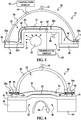
FIG. 1 , a doublevacuum chamber apparatus 20 is used to perform out-of-autoclave curing of acomposite part 22. As used herein, "part" and "composite part" are used in their broadest sense and include but are not limited to various forms of structures, such as, without limitation, beams, supports, panels, structural and non-structural members, elements and subassemblies, to name only a few. Thepart 22 may comprise a multi-ply prepreg laminate which is placed on or against atool 24 supported on ametallic tool base 26. A substantially rigidouter shroud 28 is sealed around itsouter periphery 27 to thetool base 26 by aseal 36, thereby forming a first,outer vacuum chamber 32 over thecomposite part 22. In one embodiment, theseal 36 may comprise a reusable elastomeric seal that is permanently affixed to theperiphery 27 of theouter shroud 28. Theouter shroud 28 may comprise any suitable material such as a metal or a composite that possesses sufficient rigidity to allow theshroud 28 to be substantially self-supporting and retain its shape. Theshroud 28 may possess any of various shapes both in footprint and cross section, that is suitable for covering theparticular part 22 to be cured. Theouter shroud 28 includes avacuum port 50 connected with asuitable vacuum source 25 which is operable to draw a desired vacuum in theouter vacuum chamber 32. - A flexible,
inner vacuum bag 30 contained inside theouter shroud 28 also covers thepart 22 and is sealed around itsperiphery 29 to thetool base 26, thereby forming a second,inner vacuum chamber 34 over thepart 22. Thebag 30 may comprise, for example and without limitation, a conventional one-time-use nylon bag and theseal 38 may be a conventional, non-reusable sealant. Alternatively, thebag 30 may be a reusable type made of, for example and without limitation, an elastomeric material, and theseal 38 may comprise a reusable elastomeric seal. Although not shown inFIG. 1 for purposes of clarity, additional layers of material may be placed on thepart 22, beneath theflexible bag 30, including but not limited to separator films, breathers and caul plates. - The
tool base 26 may include apassageway 46 therein which communicates with theinner vacuum chamber 34. Thepassageway 46 is coupled through avacuum port 38 to avacuum source 35 which is used to draw a desired level of vacuum within theinner vacuum chamber 34 during cure processing. Thetool base 26 may also include one ormore vent openings 40 therein to allow heat indicated by thearrows 42 from aheat source 44 to be vented directly against thetool 24. Alternatively, cure processing using theapparatus 20 may be performed within an oven (not shown) which is used to heat thecomposite part 22 to the required cure temperature. -
FIG. 2 illustrates an alternate embodiment of theapparatus 20 in which a reusable type elastomericinner vacuum bag 30 covers thecomposite part 20. Thebag 30 includes amagnetic strip 52 integrated into and surrounding the periphery of thebag 30 for holding thebag 30 against themetallic tool base 26. Thebag 30 further includes areusable vacuum seal 54 permanently bonded to thebag 30 for creating a vacuum tight seal outside of themagnetic strip 52 and surrounding thepart 22. Integration of thebag 30, themagnetic strip 52 and thereusable seal 54 into a single assembly allow thebag 30 to be quickly deployed over thepart 22 and sealed to thetool base 26. - Attention is now directed to
FIG. 3 which illustrates another embodiment of theapparatus 20 in which the inner,flexible bag 30 is permanently attached to theperiphery 27 of theouter shroud 28 so that theouter shroud 28 andinner bag 30 form a single doublevacuum chamber assembly 37 that may be easily and quickly placed on and sealed to thetool base 26, covering thepart 22. The integration of theouter shroud 28,inner bag 30 and seal 36 into asingle assembly 37 permits checking theouter shroud 28 andinner bag 30 for leaks before they are installed over thepart 22, thus reducing processing time. In this example, areusable seal 36 is attached to theperiphery 27 of theshroud 28, with theinner bag 30 sandwiched therebetween so that theseal 36 functions to seal both the outer andinner vacuum chambers tool base 26. - It should be noted here that while the various embodiments are described in connection with producing original composite parts as part of a manufacturing process, various components of the apparatus including the double
vacuum chamber assembly 37, and well as the disclosed method may be employed to rework parts or structures. For example the embodiments may be employed to cure a composite patch (not shown) and remove volatiles therefrom that is used to rework a portion of a structure such as an aircraft skin (not shown), either to improve the structure or to restore the structure to original specifications. In a rework application of the embodiments, the doublevacuum chamber assembly 37 may be placed on and sealed to the structure, rather than to atool base 26 as shown in the Figures. - Attention is now directed to
FIG. 4 which illustrates another embodiment of theapparatus 20 in which atool 24 mounted on atool base 26 includes a generally U-shaped cross section forming anopening 56 on thebackside 57 of thetool 24. Theopening 56 allows warm air shown by thearrow 58 from a suitable heat source (not shown) to circulate evenly around and directly contact thebackside 57 of thetool 24, thereby improving the transfer of heat to thecomposite part 22. In this particular example, thetool 24 includes a pair oftool surfaces part 22. Theouter shroud 28 is provided with aperipheral flange 28a which forms asurface 39 against which theseal 36 may conform to create a vacuum tight seal around theouter vacuum chamber 32. - Referring now to
FIG. 5 , a further form of theapparatus 20 includes a substantially rigidouter shroud 28 to which the innerflexible bag 30 and thereusable seal 36 are permanently attached so that theshroud 28,bag 30 andseal 36 may be installed and removed over thepart 22 as asingle assembly 37. In this example,thermocouples 60 may be provided in theshroud 28 and/or in thetool 24 in order to measure the temperature of thepart 22.Suitable displays 62 may be provided to display the temperature sensed by thethermocouples 60. In this embodiment, a radiant or other form ofheat source 65 may be placed within theopening 56 so as to be in close proximity to and direct heat along theback side 57 of thetool 24 in order to increase the efficiency and reduce the time required for heat transfer to thepart 22. -
FIG. 6 illustrates still another embodiment of theapparatus 20 in which athermal mass 64 comprising a thermally conductive material such as, without limitation, copper or aluminum, is attached to thebackside 57 of thetool 24 in order to further maximize the speed and efficiency of heat transfer to thepart 22, as well as to heat thepart 22 more uniformly. The embodiment of theapparatus 20 shown inFIG. 6 utilizes an integrated double vacuum chamber configuration, similar to that shown inFIGS. 3 and5 . Theouter periphery 29 of thebag 30 is bonded to theflange 28 on theshroud 28 by a layer ofadhesive 66. Theseal 36 is in turn bonded to theperiphery 30 of thebag 30 by a second layer ofadhesive 68. -
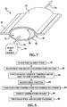
FIG. 7 illustrates an embodiment of theapparatus 20 in which anopening 56 in thebackside 57 of thetool 24 is closed by acover 70 to form aconduit 72 through thetool 24. A suitable source ofwarm air 74 may direct warm air through theconduit 72 as shown by thearrows 76 in order to directly warm thebackside 57 of thetool 24 and thus thepart 22. Theouter shroud 28 and theinner bag 30 are not shown inFIG. 7 for purposes of clarity. -
FIG. 8 illustrates the steps of a method for double vacuum curing of acomposite part 22 which employs theapparatus 20 shown inFIGS. 1-7 . Beginning at step 78, an uncuredcomposite part 22 is placed on or against asuitable cure tool 24. As shown at 80, first and second vacuums are then drawn over thepart 22 using thevacuum chambers outer shroud 28 and theinner bag 30. Atstep 82, with the first and second vacuums having been drawn, the temperature of thepart 22 is continuously increased through heating until the part temperature reaches a preselected cure temperature. As will be explained below, the part temperature is increased at a constant rate. As the temperature of thepart 22 is being increased to the cure temperature, the first vacuum is reduced to some preselected level, as shown atstep 84 so that the level of the second vacuum is greater than the level of the first vacuum. Once thepart 22 reaches the cure temperature, the cure temperature is maintained, as shown atstep 86 for a preselected period during which thepart 22 cures. After thepart 22 is cured, the temperature of thepart 22 is reduced as shown atstep 88, and the first and second vacuums are terminated as shown atstep 90. -
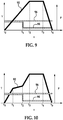
FIG. 9 illustrates vacuum pressure
and temperature profiles according to processing schedule suitable for double vacuum curing of thecomposite part 22. As previously noted however, the disclosed method utilizing the processing schedule shown inFIG. 9 may
also be used to remove volatiles and cure composite patches (not shown) used to rework an area of a part or structure. Referring toFIG. 9 , the temperature of thepart 22 indicated byplot 92 is continuously increased at a substantially constant rate from time t0 to t2 until the preselected cure temperature has been reached at t2 . Beginning at t0 , the vacuum pressures in the outer andinner vacuum chambers plots first vacuum pressure 94 in theouter vacuum chamber 32 is slightly above
thevacuum pressure 96 in theinner chamber 34. - In this embodiment, the
vacuum pressure 96 in theinner chamber 34 is maintained substantially constant during the entire process cycle. However, at some point, t1 between t0 and t2, thevacuum pressure 94 in theouter vacuum chamber 32 is reduced to a level that is materially less than thevacuum pressure 96 in theinner vacuum chamber 34. During the period between t0 and t1 , because the twopressures vacuum pressure 94 in theouter vacuum chamber 32 prevents theinner bag 30 from applying full compaction pressure on thepart 22, thereby allowing volatiles in thepart 22 to escape more readily as thetemperature 92 is being ramped up to the cure temperature. At time t1 , however, the reduction of thevacuum pressure 94 allows thevacuum pressure 96 in theinner chamber 34 to apply nearly full pressure to thepart 22 in order to compact thepart 22 and force out air pockets in thelaminate part 22 to avoid porosities. The period between t2 and t3 represents the preselected period during which thetemperature 92 is maintained at a constant cure temperature. Beginning at t3, thetemperature 92 is ramped down during a cooling cycle to an ambient temperature at t4, at which point thevacuum pressures -
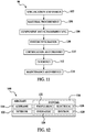
FIG. 10 illustrates a cure processing schedule, not part of the claimed invention, which is
generally similar toFIG. 9 however ramping of thetemperature 92 to the cure temperature, though continuous, is not constant, but rather includes one or more changes in the rate of temperature increase. In the illustrated example, thetemperature 92 is increased between t0 and t1 at a rate that is greater than that shown in the schedule ofFIG. 9 . However, at t1 , the rate of temperature increase is reduced until t2 at which point the temperature ramp rate is resumed until the cure temperature is reached at t3 . - Embodiments of the disclosure may find use in a variety of potential applications, particularly in the transportation industry, including for example, aerospace, marine and automotive applications. Thus, referring now to
FIGS. 11 and 12 , embodiments of the disclosure may be used in the context of an aircraft manufacturing andservice method 98 as shown inFigure 11 and anaircraft 100 as shown inFigure 12 . During pre-production,exemplary method 98 may include specification anddesign 102 of theaircraft 100 andmaterial procurement 104. During production, component andsubassembly manufacturing 106 andsystem integration 108 of theaircraft 100 takes place. The disclosed methods and apparatus may be used to cure composite parts manufactured duringstep 106 and integrated instep 108. Thereafter, theaircraft 100 may go through certification anddelivery 110 in order to be placed inservice 112. While in service by a customer, theaircraft 100 is scheduled for routine maintenance and service 114 (which may also include modification, reconfiguration, refurbishment, and so on). The disclosed methods and apparatus may be used to cure composite parts that are installed on theaircraft 100 during the maintenance andservice 114. - Each of the processes of
method 98 may be performed or carried out by a system integrator, a third party, and/or an operator (e.g., a customer). For the purposes of this description, a system integrator may include without limitation any number of aircraft manufacturers and major-system subcontractors; a third party may include without limitation any number of vendors, subcontractors, and suppliers; and an operator may be an airline, leasing company, military entity, service organization, and so on. - As shown in
FIG. 12 , theaircraft 100 produced byexemplary method 98 may include anairframe 116 with a plurality ofsystems 118 and an interior 120. Examples of high-level systems 118 include one or more of apropulsion system 122, anelectrical system 124, ahydraulic system 126, and anenvironmental system 128. Any number of other systems may be included. Although an aerospace example is shown, the principles of the disclosure may be applied to other industries, such as the marine, automotive and construction industries. - The apparatus and methods embodied herein may be employed during any one or more of the stages of the production and
service method 98. For example, components or subassemblies corresponding toproduction process 98 may be fabricated or manufactured in a manner similar to components or subassemblies produced while theaircraft 100 is in service. Also, one or more apparatus embodiments, method embodiments, or a combination thereof may be utilized during the production stages 106 and 108, for example, by substantially expediting assembly of or reducing the cost of anaircraft 100. - Similarly, one or more of apparatus embodiments, method embodiments, or a combination thereof may be utilized while the
aircraft 100 is in service, for example and without limitation, to maintenance andservice 114. - Although the embodiments of this disclosure have been described with respect to certain exemplary embodiments, it is to be understood that the specific embodiments are for purposes of illustration and not limitation, as other variations will occur to those of skill in the art.
Claims (3)
- A method of curing a composite part, comprising:placing the composite part (22) against a tool (24) having at least a first side (24a) and a second side opposite the first side (24a), the composite part placed against the first side;drawing a first vacuum and a second vacuum over the composite part (22) in, correspondingly, a first vacuum area (34) in which the composite part is located and a second vacuum area (32) outside the first vacuum area wherein the vacuum j pressure (94) of the second vacuum is slightly above the vacuum pressure (96) of the first vacuum;increasing a temperature of the composite part (22) by heating the tool and the composite part substantially continuously at a substantially constant rateuntil the tool and the composite part reach a preselected cure temperature; andbefore the temperature reaches a cure temperature of the composite part, reducing the vacuum pressure (94) of the second vacuum to a level that is materially less than the vacuum pressure of the first vacuum;maintaining the temperature of the composite part substantially at the cure
temperature for a preselected period while maintaining the vacuum pressure of the first vacuum (96) substantially constant during the entire process cycle; and
reducing the temperature of the composite part after the cure temperature
has been maintained for the preselected period; terminating the vacuums in the first and second vacuum chambers; wherein drawing the first vacuum and the second vacuum includes:placing a substantially flexible bag (30) over the composite part (22) to form the first vacuum area (34),forming a substantially vacuum tight seal between the bag (30) and the tool (24), drawing air from the bag (30) through a first vacuum port (48) in the tool (24),placing a substantially rigid shroud (28) over the bag and the composite part (22) to form the second vacuum area (32), anddrawing air from the shroud (28) through a second vacuum port (50) in the shroud (28); forming a vacuum tight seal between the bag (30) and the shroud (28). - The method of claim 1, further comprising:holding a periphery of the bag (30) against the tool using a magnet.
- A method of curing a composite part (22) as claimed in claim 1, comprising:forming, on the first side, a first outer vacuum chamber (32) over the part by placing a shroud (28) over the part to define the first vacuum area;forming, on the first side, a second inner vacuum chamber (34) over the part by placing a bag (30) over the composite part inside the shroud (28) to define the second vacuum area;forming a first substantially vacuum tight seal between the shroud (28) and the bag (30); forming a second substantially vacuum tight seal between the bag (30) and the tool (24); wherein said first vacuum is drawn in the first vacuum chamber (32); andwherein said second vacuum is drawn in the second vacuum chamber (34);
Applications Claiming Priority (2)
| Application Number | Priority Date | Filing Date | Title |
|---|---|---|---|
| US12/641,897 US20110146906A1 (en) | 2009-12-18 | 2009-12-18 | Double Vacuum Cure Processing of Composite Parts |
| PCT/US2010/056605 WO2011075252A1 (en) | 2009-12-18 | 2010-11-12 | Double vacuum cure processing of composite parts |
Publications (2)
| Publication Number | Publication Date |
|---|---|
| EP2512783A1 EP2512783A1 (en) | 2012-10-24 |
| EP2512783B1 true EP2512783B1 (en) | 2017-01-04 |
Family
ID=43502953
Family Applications (1)
| Application Number | Title | Priority Date | Filing Date |
|---|---|---|---|
| EP10779651.8A Active EP2512783B1 (en) | 2009-12-18 | 2010-11-12 | Double vacuum cure processing of composite parts |
Country Status (8)
| Country | Link |
|---|---|
| US (1) | US20110146906A1 (en) |
| EP (1) | EP2512783B1 (en) |
| JP (1) | JP5728493B2 (en) |
| CN (1) | CN102712142B (en) |
| CA (1) | CA2784378C (en) |
| ES (1) | ES2621454T3 (en) |
| PT (1) | PT2512783T (en) |
| WO (1) | WO2011075252A1 (en) |
Families Citing this family (22)
| Publication number | Priority date | Publication date | Assignee | Title |
|---|---|---|---|---|
| US8986479B2 (en) * | 2010-09-30 | 2015-03-24 | The Boeing Company | Systems and methods for on-aircraft composite repair using double vacuum debulking |
| NL2006202C2 (en) | 2011-02-15 | 2012-08-16 | Rapspice | A solar cell laminate comprising crystalline silicon photo-electricity device and process to make such a laminate. |
| US8628639B2 (en) | 2011-05-28 | 2014-01-14 | The Boeing Company | Vacuum bag processing using dual seals |
| CN102350803B (en) * | 2011-06-24 | 2014-05-28 | 中国航空工业集团公司北京航空制造工程研究所 | Encapsulation method for reducing vacuum leakage in composite material formation |
| US20130143006A1 (en) * | 2011-12-02 | 2013-06-06 | The Boeing Company | Reducing Porosity in Composite Structures |
| CN104441699A (en) * | 2014-12-31 | 2015-03-25 | 江苏中陆航星航空工业有限公司 | Vacuum bag reusing structure |
| FR3039452B1 (en) * | 2015-07-27 | 2017-12-22 | Airbus | METHOD FOR REPAIRING A COMPOSITE MATERIAL PANEL OF AN AIRCRAFT AND TOOLING FOR ITS IMPLEMENTATION |
| US10343353B2 (en) * | 2015-10-06 | 2019-07-09 | The Boeing Company | Method of curing a composite article using differential vacuum |
| US10220605B2 (en) * | 2015-11-10 | 2019-03-05 | The Boeing Company | Edge breathers for composite products |
| CN106808713A (en) * | 2015-11-30 | 2017-06-09 | 比亚迪股份有限公司 | A kind of method of resin-fiber composite and its vacuum flexible bag moulding |
| US10773428B2 (en) | 2016-01-07 | 2020-09-15 | The Boeing Company | Vacuum port base |
| US10357922B2 (en) * | 2016-01-07 | 2019-07-23 | The Boeing Company | Edge breathers for composite products |
| US10974467B2 (en) * | 2016-02-12 | 2021-04-13 | The Boeing Company | Enhanced systems that facilitate vacuum bag curing of composite parts |
| US10953575B2 (en) | 2016-02-12 | 2021-03-23 | The Boeing Company | Enhanced systems that facilitate vacuum bag curing of composite parts |
| CN106393747A (en) * | 2016-09-21 | 2017-02-15 | 中国商用飞机有限责任公司 | Process forming device for double-vacuum hot bonder |
| US11097524B2 (en) * | 2017-05-26 | 2021-08-24 | The Boeing Company | Flexible vacuum securement of objects to complex surfaces |
| CN110654042A (en) * | 2018-06-29 | 2020-01-07 | 成都飞机工业(集团)有限责任公司 | Vacuum compaction method for reducing porosity of composite material member |
| CN109094052B (en) * | 2018-09-30 | 2020-11-10 | 航天特种材料及工艺技术研究所 | Vacuum bag packaging method for autoclave molding |
| DE102019005912A1 (en) * | 2019-08-22 | 2021-02-25 | Siempelkamp Maschinen- Und Anlagenbau Gmbh | Method and device for manufacturing a component from a fiber composite material |
| KR102148811B1 (en) * | 2020-04-06 | 2020-08-27 | (주)아름덴티스트리 | UV-LED curing device |
| EP4008534A1 (en) * | 2020-12-03 | 2022-06-08 | LM Wind Power A/S | Method of manufacturing a spar cap for a wind turbine blade |
| EP4446100A1 (en) * | 2023-04-14 | 2024-10-16 | Siemens Gamesa Renewable Energy A/S | Moulding apparatus |
Citations (1)
| Publication number | Priority date | Publication date | Assignee | Title |
|---|---|---|---|---|
| US6482497B1 (en) * | 1998-11-30 | 2002-11-19 | Rocky Mountain Composites Inc. | Pressure-cycled, packet-transfer infusion of resin-stitched preforms |
Family Cites Families (26)
| Publication number | Priority date | Publication date | Assignee | Title |
|---|---|---|---|---|
| US4357193A (en) * | 1979-05-21 | 1982-11-02 | Rockwell International Corporation | Method of fabricating a composite structure |
| GB2124130B (en) * | 1982-07-24 | 1985-11-27 | Rolls Royce | Vacuum moulding fibre reinforced resin |
| US4822651A (en) * | 1985-08-30 | 1989-04-18 | Newsom Cosby M | Vacuum diaphragm device |
| US5087193A (en) * | 1990-08-09 | 1992-02-11 | Herbert Jr Kenneth H | Apparatus for forming a composite article |
| US5236646A (en) * | 1991-02-28 | 1993-08-17 | The United States Of America As Represented By The Secretary Of The Navy | Process for preparing thermoplastic composites |
| US5665301A (en) * | 1995-07-11 | 1997-09-09 | Arctek Inc. | Apparatus and method for forming fiber reinforced composite articles |
| US6017484A (en) * | 1997-01-21 | 2000-01-25 | Harold P. Hale | Method for manufacture of minimum porosity, wrinkle free composite parts |
| US6299819B1 (en) * | 1998-07-27 | 2001-10-09 | The University Of Dayton | Double-chamber vacuum resin transfer molding |
| WO2001041993A2 (en) * | 1999-12-07 | 2001-06-14 | The Boeing Company | Double bag vacuum infusion process and system for low cost, advanced composite fabrication |
| US6761783B2 (en) * | 2002-04-09 | 2004-07-13 | The Boeing Company | Process method to repair bismaleimide (BMI) composite structures |
| JP2005527410A (en) * | 2002-05-29 | 2005-09-15 | ザ・ボーイング・カンパニー | Controlled atmospheric pressure resin injection process |
| DE102004021337B4 (en) * | 2004-04-30 | 2009-12-03 | Webasto Ag | Method for producing a composite body part for a vehicle |
| US7186367B2 (en) * | 2004-05-13 | 2007-03-06 | The United States Of America As Represented By The Administrator Of The National Aeronautics And Space Administration | Double vacuum bag process for resin matrix composite manufacturing |
| US20050281980A1 (en) * | 2004-06-22 | 2005-12-22 | Cruz Jose A | Vacuum pressure bag for use with large scale composite structures |
| US8052831B2 (en) * | 2005-02-02 | 2011-11-08 | The Boeing Company | Low temperature, vacuum cure fabrication process for large, honeycomb core stiffened composite structures |
| JP2006334912A (en) * | 2005-06-01 | 2006-12-14 | Dainippon Printing Co Ltd | Lamination device |
| US20070296126A1 (en) * | 2006-06-21 | 2007-12-27 | Audette Lawrence F | Reusable silicone vacuum bag/tool flange sealing method |
| GB0613872D0 (en) * | 2006-07-12 | 2006-08-23 | Airbus Uk Ltd | Method of manufacturing composite part |
| US7862679B2 (en) * | 2006-08-09 | 2011-01-04 | The Boeing Company | Integral double bag for vacuum bagging a composite part and method of using the same |
| JP5271486B2 (en) * | 2006-08-16 | 2013-08-21 | 株式会社ブリヂストン | Release agent, method for forming concave / convex pattern using the same, method for producing optical information recording medium, and optical information recording medium |
| US20080083493A1 (en) * | 2006-10-10 | 2008-04-10 | Ridges Michael D | Reusable mechanical fastener and vacuum seal combination |
| US7849729B2 (en) * | 2006-12-22 | 2010-12-14 | The Boeing Company | Leak detection in vacuum bags |
| US7857925B2 (en) * | 2007-06-15 | 2010-12-28 | The Boeing Company | Process development protocol and vacuum bag process for carbon-epoxy prepreg |
| US8105068B2 (en) * | 2008-11-05 | 2012-01-31 | Spirit Aerosystems, Inc. | Reusable infusion bag |
| US20100308515A1 (en) * | 2009-06-05 | 2010-12-09 | Astoria Industries Of Iowa, Inc. | Apparatus and process for manufacturing a vacuum molded fiberglass chipper body |
| US8628639B2 (en) * | 2011-05-28 | 2014-01-14 | The Boeing Company | Vacuum bag processing using dual seals |
-
2009
- 2009-12-18 US US12/641,897 patent/US20110146906A1/en not_active Abandoned
-
2010
- 2010-11-12 ES ES10779651.8T patent/ES2621454T3/en active Active
- 2010-11-12 JP JP2012544528A patent/JP5728493B2/en active Active
- 2010-11-12 CN CN201080057416.7A patent/CN102712142B/en active Active
- 2010-11-12 WO PCT/US2010/056605 patent/WO2011075252A1/en active Application Filing
- 2010-11-12 PT PT107796518T patent/PT2512783T/en unknown
- 2010-11-12 CA CA2784378A patent/CA2784378C/en active Active
- 2010-11-12 EP EP10779651.8A patent/EP2512783B1/en active Active
Patent Citations (1)
| Publication number | Priority date | Publication date | Assignee | Title |
|---|---|---|---|---|
| US6482497B1 (en) * | 1998-11-30 | 2002-11-19 | Rocky Mountain Composites Inc. | Pressure-cycled, packet-transfer infusion of resin-stitched preforms |
Also Published As
| Publication number | Publication date |
|---|---|
| US20110146906A1 (en) | 2011-06-23 |
| JP2013514209A (en) | 2013-04-25 |
| JP5728493B2 (en) | 2015-06-03 |
| CA2784378A1 (en) | 2011-06-23 |
| CN102712142B (en) | 2015-12-16 |
| WO2011075252A1 (en) | 2011-06-23 |
| CA2784378C (en) | 2019-01-08 |
| EP2512783A1 (en) | 2012-10-24 |
| CN102712142A (en) | 2012-10-03 |
| PT2512783T (en) | 2017-02-01 |
| ES2621454T3 (en) | 2017-07-04 |
Similar Documents
| Publication | Publication Date | Title |
|---|---|---|
| EP2512783B1 (en) | Double vacuum cure processing of composite parts | |
| EP2529919B1 (en) | Vacuum bag processing using dual seals | |
| US8444127B2 (en) | High temperature composite patch tool | |
| JP6659749B2 (en) | Composite tool with vacuum integrity and method of manufacturing the same | |
| EP2565005B1 (en) | Integrally stiffened, reusable vacuum bag and method of making the same | |
| EP2671709B1 (en) | Non-vented bladder system for curing composite parts | |
| US11400620B2 (en) | Methods and apparatus for curing composite nacelle structure | |
| US7842209B2 (en) | Vacuum debulk and radiation cure method | |
| EP2632723B1 (en) | Single stage debulk and cure of a prepreg material | |
| US11904560B2 (en) | Vacuum bag-less composite repair systems and methods | |
| US9862154B2 (en) | Apparatuses and methods for efficient sealing of vacuum bag seams | |
| US20090218713A1 (en) | Vacuum heat-set of net shape latex vacuum bags | |
| US6991449B1 (en) | Heating apparatus for in-situ de-bulking composite parts during layup | |
| US6565690B1 (en) | Process for manufacturing structures of composite material | |
| CN114536813A (en) | Apparatus and method for processing composite structures | |
| CN114536803A (en) | Apparatus and method for processing composite structures |
Legal Events
| Date | Code | Title | Description |
|---|---|---|---|
| PUAI | Public reference made under article 153(3) epc to a published international application that has entered the european phase |
Free format text: ORIGINAL CODE: 0009012 |
|
| 17P | Request for examination filed |
Effective date: 20120718 |
|
| AK | Designated contracting states |
Kind code of ref document: A1 Designated state(s): AL AT BE BG CH CY CZ DE DK EE ES FI FR GB GR HR HU IE IS IT LI LT LU LV MC MK MT NL NO PL PT RO RS SE SI SK SM TR |
|
| DAX | Request for extension of the european patent (deleted) | ||
| 17Q | First examination report despatched |
Effective date: 20130429 |
|
| GRAP | Despatch of communication of intention to grant a patent |
Free format text: ORIGINAL CODE: EPIDOSNIGR1 |
|
| INTG | Intention to grant announced |
Effective date: 20160609 |
|
| GRAS | Grant fee paid |
Free format text: ORIGINAL CODE: EPIDOSNIGR3 |
|
| GRAA | (expected) grant |
Free format text: ORIGINAL CODE: 0009210 |
|
| AK | Designated contracting states |
Kind code of ref document: B1 Designated state(s): AL AT BE BG CH CY CZ DE DK EE ES FI FR GB GR HR HU IE IS IT LI LT LU LV MC MK MT NL NO PL PT RO RS SE SI SK SM TR |
|
| REG | Reference to a national code |
Ref country code: GB Ref legal event code: FG4D |
|
| REG | Reference to a national code |
Ref country code: CH Ref legal event code: EP |
|
| REG | Reference to a national code |
Ref country code: AT Ref legal event code: REF Ref document number: 858812 Country of ref document: AT Kind code of ref document: T Effective date: 20170115 |
|
| REG | Reference to a national code |
Ref country code: IE Ref legal event code: FG4D |
|
| REG | Reference to a national code |
Ref country code: PT Ref legal event code: SC4A Ref document number: 2512783 Country of ref document: PT Date of ref document: 20170201 Kind code of ref document: T Free format text: AVAILABILITY OF NATIONAL TRANSLATION Effective date: 20170120 |
|
| REG | Reference to a national code |
Ref country code: DE Ref legal event code: R096 Ref document number: 602010039356 Country of ref document: DE |
|
| REG | Reference to a national code |
Ref country code: SE Ref legal event code: TRGR |
|
| REG | Reference to a national code |
Ref country code: LT Ref legal event code: MG4D Ref country code: NL Ref legal event code: MP Effective date: 20170104 |
|
| REG | Reference to a national code |
Ref country code: AT Ref legal event code: MK05 Ref document number: 858812 Country of ref document: AT Kind code of ref document: T Effective date: 20170104 |
|
| PG25 | Lapsed in a contracting state [announced via postgrant information from national office to epo] |
Ref country code: NL Free format text: LAPSE BECAUSE OF FAILURE TO SUBMIT A TRANSLATION OF THE DESCRIPTION OR TO PAY THE FEE WITHIN THE PRESCRIBED TIME-LIMIT Effective date: 20170104 |
|
| REG | Reference to a national code |
Ref country code: ES Ref legal event code: FG2A Ref document number: 2621454 Country of ref document: ES Kind code of ref document: T3 Effective date: 20170704 |
|
| PG25 | Lapsed in a contracting state [announced via postgrant information from national office to epo] |
Ref country code: IS Free format text: LAPSE BECAUSE OF FAILURE TO SUBMIT A TRANSLATION OF THE DESCRIPTION OR TO PAY THE FEE WITHIN THE PRESCRIBED TIME-LIMIT Effective date: 20170504 Ref country code: GR Free format text: LAPSE BECAUSE OF FAILURE TO SUBMIT A TRANSLATION OF THE DESCRIPTION OR TO PAY THE FEE WITHIN THE PRESCRIBED TIME-LIMIT Effective date: 20170405 Ref country code: FI Free format text: LAPSE BECAUSE OF FAILURE TO SUBMIT A TRANSLATION OF THE DESCRIPTION OR TO PAY THE FEE WITHIN THE PRESCRIBED TIME-LIMIT Effective date: 20170104 Ref country code: NO Free format text: LAPSE BECAUSE OF FAILURE TO SUBMIT A TRANSLATION OF THE DESCRIPTION OR TO PAY THE FEE WITHIN THE PRESCRIBED TIME-LIMIT Effective date: 20170404 Ref country code: LT Free format text: LAPSE BECAUSE OF FAILURE TO SUBMIT A TRANSLATION OF THE DESCRIPTION OR TO PAY THE FEE WITHIN THE PRESCRIBED TIME-LIMIT Effective date: 20170104 Ref country code: HR Free format text: LAPSE BECAUSE OF FAILURE TO SUBMIT A TRANSLATION OF THE DESCRIPTION OR TO PAY THE FEE WITHIN THE PRESCRIBED TIME-LIMIT Effective date: 20170104 |
|
| PG25 | Lapsed in a contracting state [announced via postgrant information from national office to epo] |
Ref country code: AT Free format text: LAPSE BECAUSE OF FAILURE TO SUBMIT A TRANSLATION OF THE DESCRIPTION OR TO PAY THE FEE WITHIN THE PRESCRIBED TIME-LIMIT Effective date: 20170104 Ref country code: PL Free format text: LAPSE BECAUSE OF FAILURE TO SUBMIT A TRANSLATION OF THE DESCRIPTION OR TO PAY THE FEE WITHIN THE PRESCRIBED TIME-LIMIT Effective date: 20170104 Ref country code: RS Free format text: LAPSE BECAUSE OF FAILURE TO SUBMIT A TRANSLATION OF THE DESCRIPTION OR TO PAY THE FEE WITHIN THE PRESCRIBED TIME-LIMIT Effective date: 20170104 Ref country code: LV Free format text: LAPSE BECAUSE OF FAILURE TO SUBMIT A TRANSLATION OF THE DESCRIPTION OR TO PAY THE FEE WITHIN THE PRESCRIBED TIME-LIMIT Effective date: 20170104 Ref country code: BG Free format text: LAPSE BECAUSE OF FAILURE TO SUBMIT A TRANSLATION OF THE DESCRIPTION OR TO PAY THE FEE WITHIN THE PRESCRIBED TIME-LIMIT Effective date: 20170404 |
|
| REG | Reference to a national code |
Ref country code: DE Ref legal event code: R097 Ref document number: 602010039356 Country of ref document: DE |
|
| PG25 | Lapsed in a contracting state [announced via postgrant information from national office to epo] |
Ref country code: RO Free format text: LAPSE BECAUSE OF FAILURE TO SUBMIT A TRANSLATION OF THE DESCRIPTION OR TO PAY THE FEE WITHIN THE PRESCRIBED TIME-LIMIT Effective date: 20170104 Ref country code: EE Free format text: LAPSE BECAUSE OF FAILURE TO SUBMIT A TRANSLATION OF THE DESCRIPTION OR TO PAY THE FEE WITHIN THE PRESCRIBED TIME-LIMIT Effective date: 20170104 Ref country code: CZ Free format text: LAPSE BECAUSE OF FAILURE TO SUBMIT A TRANSLATION OF THE DESCRIPTION OR TO PAY THE FEE WITHIN THE PRESCRIBED TIME-LIMIT Effective date: 20170104 Ref country code: SK Free format text: LAPSE BECAUSE OF FAILURE TO SUBMIT A TRANSLATION OF THE DESCRIPTION OR TO PAY THE FEE WITHIN THE PRESCRIBED TIME-LIMIT Effective date: 20170104 |
|
| PLBE | No opposition filed within time limit |
Free format text: ORIGINAL CODE: 0009261 |
|
| STAA | Information on the status of an ep patent application or granted ep patent |
Free format text: STATUS: NO OPPOSITION FILED WITHIN TIME LIMIT |
|
| REG | Reference to a national code |
Ref country code: FR Ref legal event code: PLFP Year of fee payment: 8 |
|
| PG25 | Lapsed in a contracting state [announced via postgrant information from national office to epo] |
Ref country code: SM Free format text: LAPSE BECAUSE OF FAILURE TO SUBMIT A TRANSLATION OF THE DESCRIPTION OR TO PAY THE FEE WITHIN THE PRESCRIBED TIME-LIMIT Effective date: 20170104 Ref country code: DK Free format text: LAPSE BECAUSE OF FAILURE TO SUBMIT A TRANSLATION OF THE DESCRIPTION OR TO PAY THE FEE WITHIN THE PRESCRIBED TIME-LIMIT Effective date: 20170104 |
|
| 26N | No opposition filed |
Effective date: 20171005 |
|
| PG25 | Lapsed in a contracting state [announced via postgrant information from national office to epo] |
Ref country code: SI Free format text: LAPSE BECAUSE OF FAILURE TO SUBMIT A TRANSLATION OF THE DESCRIPTION OR TO PAY THE FEE WITHIN THE PRESCRIBED TIME-LIMIT Effective date: 20170104 |
|
| PG25 | Lapsed in a contracting state [announced via postgrant information from national office to epo] |
Ref country code: MC Free format text: LAPSE BECAUSE OF FAILURE TO SUBMIT A TRANSLATION OF THE DESCRIPTION OR TO PAY THE FEE WITHIN THE PRESCRIBED TIME-LIMIT Effective date: 20170104 |
|
| PG25 | Lapsed in a contracting state [announced via postgrant information from national office to epo] |
Ref country code: CH Free format text: LAPSE BECAUSE OF NON-PAYMENT OF DUE FEES Effective date: 20171130 Ref country code: LI Free format text: LAPSE BECAUSE OF NON-PAYMENT OF DUE FEES Effective date: 20171130 |
|
| PG25 | Lapsed in a contracting state [announced via postgrant information from national office to epo] |
Ref country code: LU Free format text: LAPSE BECAUSE OF NON-PAYMENT OF DUE FEES Effective date: 20171112 |
|
| REG | Reference to a national code |
Ref country code: BE Ref legal event code: MM Effective date: 20171130 |
|
| REG | Reference to a national code |
Ref country code: IE Ref legal event code: MM4A |
|
| PG25 | Lapsed in a contracting state [announced via postgrant information from national office to epo] |
Ref country code: MT Free format text: LAPSE BECAUSE OF NON-PAYMENT OF DUE FEES Effective date: 20171112 |
|
| PG25 | Lapsed in a contracting state [announced via postgrant information from national office to epo] |
Ref country code: IE Free format text: LAPSE BECAUSE OF NON-PAYMENT OF DUE FEES Effective date: 20171112 |
|
| PG25 | Lapsed in a contracting state [announced via postgrant information from national office to epo] |
Ref country code: BE Free format text: LAPSE BECAUSE OF NON-PAYMENT OF DUE FEES Effective date: 20171130 |
|
| PG25 | Lapsed in a contracting state [announced via postgrant information from national office to epo] |
Ref country code: HU Free format text: LAPSE BECAUSE OF FAILURE TO SUBMIT A TRANSLATION OF THE DESCRIPTION OR TO PAY THE FEE WITHIN THE PRESCRIBED TIME-LIMIT; INVALID AB INITIO Effective date: 20101112 |
|
| PG25 | Lapsed in a contracting state [announced via postgrant information from national office to epo] |
Ref country code: CY Free format text: LAPSE BECAUSE OF NON-PAYMENT OF DUE FEES Effective date: 20170104 |
|
| PG25 | Lapsed in a contracting state [announced via postgrant information from national office to epo] |
Ref country code: MK Free format text: LAPSE BECAUSE OF FAILURE TO SUBMIT A TRANSLATION OF THE DESCRIPTION OR TO PAY THE FEE WITHIN THE PRESCRIBED TIME-LIMIT Effective date: 20170104 |
|
| PG25 | Lapsed in a contracting state [announced via postgrant information from national office to epo] |
Ref country code: TR Free format text: LAPSE BECAUSE OF FAILURE TO SUBMIT A TRANSLATION OF THE DESCRIPTION OR TO PAY THE FEE WITHIN THE PRESCRIBED TIME-LIMIT Effective date: 20170104 |
|
| PG25 | Lapsed in a contracting state [announced via postgrant information from national office to epo] |
Ref country code: AL Free format text: LAPSE BECAUSE OF FAILURE TO SUBMIT A TRANSLATION OF THE DESCRIPTION OR TO PAY THE FEE WITHIN THE PRESCRIBED TIME-LIMIT Effective date: 20170104 |
|
| REG | Reference to a national code |
Ref country code: DE Ref legal event code: R082 Ref document number: 602010039356 Country of ref document: DE Representative=s name: KILBURN & STRODE LLP, NL |
|
| P01 | Opt-out of the competence of the unified patent court (upc) registered |
Effective date: 20230516 |
|
| PGFP | Annual fee paid to national office [announced via postgrant information from national office to epo] |
Ref country code: GB Payment date: 20231127 Year of fee payment: 14 |
|
| PGFP | Annual fee paid to national office [announced via postgrant information from national office to epo] |
Ref country code: ES Payment date: 20231201 Year of fee payment: 14 |
|
| PGFP | Annual fee paid to national office [announced via postgrant information from national office to epo] |
Ref country code: SE Payment date: 20231127 Year of fee payment: 14 Ref country code: PT Payment date: 20231024 Year of fee payment: 14 Ref country code: IT Payment date: 20231122 Year of fee payment: 14 Ref country code: FR Payment date: 20231127 Year of fee payment: 14 Ref country code: DE Payment date: 20231129 Year of fee payment: 14 |