EP2511556B1 - Sternfeder und ein Verfahren zu ihrer Herstellung - Google Patents
Sternfeder und ein Verfahren zu ihrer Herstellung Download PDFInfo
- Publication number
- EP2511556B1 EP2511556B1 EP20120002190 EP12002190A EP2511556B1 EP 2511556 B1 EP2511556 B1 EP 2511556B1 EP 20120002190 EP20120002190 EP 20120002190 EP 12002190 A EP12002190 A EP 12002190A EP 2511556 B1 EP2511556 B1 EP 2511556B1
- Authority
- EP
- European Patent Office
- Prior art keywords
- spring
- star
- sectors
- base body
- interstices
- Prior art date
- Legal status (The legal status is an assumption and is not a legal conclusion. Google has not performed a legal analysis and makes no representation as to the accuracy of the status listed.)
- Not-in-force
Links
- 238000004519 manufacturing process Methods 0.000 title claims description 5
- 238000000034 method Methods 0.000 title claims description 3
- 230000008878 coupling Effects 0.000 claims description 7
- 238000010168 coupling process Methods 0.000 claims description 7
- 238000005859 coupling reaction Methods 0.000 claims description 7
- 229910000639 Spring steel Inorganic materials 0.000 claims description 2
- 230000002349 favourable effect Effects 0.000 description 4
- 239000002184 metal Substances 0.000 description 3
- 238000009826 distribution Methods 0.000 description 2
- 230000005540 biological transmission Effects 0.000 description 1
- 230000001419 dependent effect Effects 0.000 description 1
- 238000006073 displacement reaction Methods 0.000 description 1
- 238000002360 preparation method Methods 0.000 description 1
- 239000002699 waste material Substances 0.000 description 1
Images


Classifications
-
- F—MECHANICAL ENGINEERING; LIGHTING; HEATING; WEAPONS; BLASTING
- F16—ENGINEERING ELEMENTS AND UNITS; GENERAL MEASURES FOR PRODUCING AND MAINTAINING EFFECTIVE FUNCTIONING OF MACHINES OR INSTALLATIONS; THERMAL INSULATION IN GENERAL
- F16D—COUPLINGS FOR TRANSMITTING ROTATION; CLUTCHES; BRAKES
- F16D27/00—Magnetically- or electrically- actuated clutches; Control or electric circuits therefor
- F16D27/10—Magnetically- or electrically- actuated clutches; Control or electric circuits therefor with an electromagnet not rotating with a clutching member, i.e. without collecting rings
- F16D27/108—Magnetically- or electrically- actuated clutches; Control or electric circuits therefor with an electromagnet not rotating with a clutching member, i.e. without collecting rings with axially movable clutching members
- F16D27/112—Magnetically- or electrically- actuated clutches; Control or electric circuits therefor with an electromagnet not rotating with a clutching member, i.e. without collecting rings with axially movable clutching members with flat friction surfaces, e.g. discs
-
- F—MECHANICAL ENGINEERING; LIGHTING; HEATING; WEAPONS; BLASTING
- F16—ENGINEERING ELEMENTS AND UNITS; GENERAL MEASURES FOR PRODUCING AND MAINTAINING EFFECTIVE FUNCTIONING OF MACHINES OR INSTALLATIONS; THERMAL INSULATION IN GENERAL
- F16D—COUPLINGS FOR TRANSMITTING ROTATION; CLUTCHES; BRAKES
- F16D27/00—Magnetically- or electrically- actuated clutches; Control or electric circuits therefor
- F16D27/14—Details
-
- F—MECHANICAL ENGINEERING; LIGHTING; HEATING; WEAPONS; BLASTING
- F16—ENGINEERING ELEMENTS AND UNITS; GENERAL MEASURES FOR PRODUCING AND MAINTAINING EFFECTIVE FUNCTIONING OF MACHINES OR INSTALLATIONS; THERMAL INSULATION IN GENERAL
- F16F—SPRINGS; SHOCK-ABSORBERS; MEANS FOR DAMPING VIBRATION
- F16F1/00—Springs
- F16F1/02—Springs made of steel or other material having low internal friction; Wound, torsion, leaf, cup, ring or the like springs, the material of the spring not being relevant
- F16F1/32—Belleville-type springs
- F16F1/324—Belleville-type springs characterised by having tongues or arms directed in a generally radial direction, i.e. diaphragm-type springs
-
- F—MECHANICAL ENGINEERING; LIGHTING; HEATING; WEAPONS; BLASTING
- F16—ENGINEERING ELEMENTS AND UNITS; GENERAL MEASURES FOR PRODUCING AND MAINTAINING EFFECTIVE FUNCTIONING OF MACHINES OR INSTALLATIONS; THERMAL INSULATION IN GENERAL
- F16D—COUPLINGS FOR TRANSMITTING ROTATION; CLUTCHES; BRAKES
- F16D27/00—Magnetically- or electrically- actuated clutches; Control or electric circuits therefor
- F16D2027/008—Details relating to the magnetic circuit, or to the shape of the clutch parts to achieve a certain magnetic path
-
- F—MECHANICAL ENGINEERING; LIGHTING; HEATING; WEAPONS; BLASTING
- F16—ENGINEERING ELEMENTS AND UNITS; GENERAL MEASURES FOR PRODUCING AND MAINTAINING EFFECTIVE FUNCTIONING OF MACHINES OR INSTALLATIONS; THERMAL INSULATION IN GENERAL
- F16D—COUPLINGS FOR TRANSMITTING ROTATION; CLUTCHES; BRAKES
- F16D2250/00—Manufacturing; Assembly
- F16D2250/0061—Joining
-
- F—MECHANICAL ENGINEERING; LIGHTING; HEATING; WEAPONS; BLASTING
- F16—ENGINEERING ELEMENTS AND UNITS; GENERAL MEASURES FOR PRODUCING AND MAINTAINING EFFECTIVE FUNCTIONING OF MACHINES OR INSTALLATIONS; THERMAL INSULATION IN GENERAL
- F16D—COUPLINGS FOR TRANSMITTING ROTATION; CLUTCHES; BRAKES
- F16D2300/00—Special features for couplings or clutches
- F16D2300/12—Mounting or assembling
Definitions
- the invention relates to a star spring according to the preamble of claim 1 and a method for their preparation.
- Star springs are used as return springs in electromagnetically actuated clutches or brakes or clutch / brake combinations. They consist of an annular disc-shaped base body, from which emanate several, radially inwardly or outwardly directed fingers. The main body is usually attached to a position-immutable component, while the free ends of the fingers engage in a circumferential groove on the anchor member or attached to an anchor plate.
- the return spring is a star spring.
- the fingers of the star spring are provided radially outward on the circumference, and it may prove expedient that the star spring consists of several segments.
- a clutch-brake combination which has an annular spring with star-shaped radially outwardly facing tabs as the return spring.
- the tabs are clamped between two anchor plates by means of screws and connected by radially inner arms, which extend substantially concentric to a rotation axis.
- the arms are connected between the tabs via webs with an inner ring area. This is fastened by means of screws to a drive hub.
- the invention has for its object to make a star pen so that it is easy and inexpensive to manufacture. It is achieved according to the invention by the features of claim 1. Further advantageous embodiments will be apparent from the dependent claims.
- the spring sectors are separated by parting lines, which are arranged in the region of the base body between the fingers.
- spring sectors for twenty-seven star-feathers can be cut with six fingers compared to fourteen common, undivided star-shaped springs.
- the production costs can be significantly reduced.
- the joints may be straight in the radial direction.
- the individual spring sectors can center each other and / or support each other.
- the spring sectors can be fastened by screws to a drive hub.
- the hole pattern for the screw holes of the usual undivided star spring can be used, in each case a screw hole in the circumferential direction is arranged approximately centrally to the respective spring sector or finger.
- additional screw holes can be provided in the parting lines. It may be appropriate that a pressure plate bridges the parting line, so that in the region of the parting line a favorable power transmission is ensured.
- a screw hole is provided in the circumferential direction on both sides of each parting line in their vicinity. As a result, a favorable attachment of the spring sectors is achieved in the region of the parting line. Again, the conditions can be improved by a pressure plate, which bridges the parting line and is secured with the associated screws on the drive hub.
- Such a star spring is a favorable return spring for electromagnetically actuated clutches or brakes or clutch-brake combinations, which can be manufactured in a favorable manufacturing process by individual spring sectors of a sheet, z. B. by laser beams, cut out and assembled during assembly to a star pen.
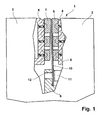
- coupling brake combination has a brake member 2 with a pole ring 4 and a coupling part 3 with a pole ring 5.
- anchor plates 6 and 7 are arranged, which are alternatively flooded by the pole rings 4 and 5.
- the flooding 8 is indicated by a dot-dash line.
- a star spring 10 is provided between the anchor plates 6 and 7, a star spring 10 is provided. This has in the execution after Fig. 2 and Fig. 3 a base body 17 on which radially outwardly directed fingers are formed.
- the star spring 10 is bounded in the radial direction by an inner circle 15 and by an outer circle 16.
- the main body 17 is divided by parting lines 19, which extend substantially radially between two adjacent fingers, so that spring sectors 20, 21, 22 arise.
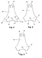
- the spring sectors 20, 21, 22 are in the 4 to 6 shown as individual elements.
- the spring sector 20 has in the region of the main body 17 rectilinear radial boundaries, which form the boundary of a parting line 19 in the assembled state.
- a screw hole 13 which is arranged in the circumferential direction seen in the middle of the base body portion 17 is used. Through the screw hole 13, a screw 11 is inserted, which engages in a threaded bore 12 of the drive hub 9.
- the drive hub 9, the brake member 2 and the coupling part 3 are axially fixed to each other.
- the spring sectors 20, 21, 22 have in the region of their outer circle 16, two screw holes 18 which are offset from one another in the circumferential direction, and which serve for fastening 20 of the spring sectors 20, 21, 22 and the star spring 10 to the anchor plates 6, 7.
- the axial position of the brake member 2, the coupling part 3 and the drive hub 9 is coordinated so that in the de-energized state of the clutch brake combination 1, the anchor plate 6 on the pole ring 4 of the brake member 2 under a bias the star spring 10 is present. If the electromagnet of the coupling part 3 is energized, the armature plate 7 is attracted by the pole ring 5, so that it comes to rest against the facing end face of the pole ring 5. For the axial displacement of the anchor plates 6, 7, a sufficient gap is provided between the anchor plates 6, 7.
- the spring sectors 20 in the embodiment according to Fig. 3 differ from the spring sector 20 in the embodiment according to Fig. 6
- two screw holes 13 are provided per spring sector 20 in the region of the base body 17, so that a screw hole 13 is arranged on both sides of a parting line 19 at a small distance therefrom.
- pressure plates 25 are provided which bridge the associated parting line 19 and are secured with the corresponding screws 11 with the spring sector 20 on the drive hub 9.
- the spring sector 21 after Fig. 5 differs from the spring sector 20 after Fig. 6 in that in the region of the parting line 19, an additional screw hole 14 is arranged, which is divided by the parting line 19 in two halves.
- the parting line 19 is expediently bridged for better pressure distribution by a pressure plate 26 in the form of an annular disc.
- the spring sector 22 after Fig. 2 and Fig. 4 differ from the spring sector 21 in that the boundary of the parting lines in the radial direction profiles 23 and 24, which fit together and engage in the assembled state.
- 22 identical profiles 23 may be arranged on a spring sector, while at the adjacent spring sectors 22 matching profiles 24 are provided.
- all spring sectors 22 in the circumferential direction alternately have a profile of a type 23 and on the other side the profile of the matching type 24.
- a metal sheet 27 which shows a pattern for spring sectors 22 of a six-fingered star spring 10.
- 27 spring sectors 22 for 27 star springs can be cut from a conventional spring plate, for example by laser beams.
- only a maximum of fourteen undivided star springs 28, each having six fingers 29 of conventional design, can be manufactured from the same spring plate 27.
Landscapes
- Engineering & Computer Science (AREA)
- General Engineering & Computer Science (AREA)
- Mechanical Engineering (AREA)
- Physics & Mathematics (AREA)
- Electromagnetism (AREA)
- Mechanical Operated Clutches (AREA)
- Springs (AREA)
- Braking Arrangements (AREA)
Description
- Die Erfindung betrifft eine Sternfeder nach dem Oberbegriff des Anspruchs 1 und ein Verfahren zu ihrer Herstellung.
- Sternfedern werden als Rückstellfedern bei elektromagnetisch betätigten Kupplungen oder Bremsen oder Kupplungs-Bremskombinationen verwendet. Sie bestehen aus einem ringscheibenförmigen Grundkörper, von dem aus mehrere, radial nach innen oder nach außen gerichtete Finger ausgehen. Der Grundkörper ist in der Regel an einem lageunveränderlichen Bauteil befestigt, während die freien Enden der Finger in einer umlaufenden Nut am Ankerteil angreifen oder an einer Ankerplatte befestigt sind.
- Aus der
DE 28 44 925 A 1 ist eine elektromagnetische Kupplung oder Bremse bekannt, deren Rückstellfeder eine Sternfeder ist. In der bevorzugten Ausführungsform sind die Finger der Sternfeder radial nach außen weisend am Umfang vorgesehen, wobei es sich als zweckmäßig erweisen kann, dass die Sternfeder aus mehreren Segmenten besteht. - Ferner ist aus der
DE 10 2004 040 251 A 1 eine Kupplungs-Bremskombination bekannt, die als Rückstellfeder eine Ringfeder mit sternförmig radial nach außen weisenden Laschen besitzt. Die Laschen sind zwischen zwei Ankerplatten mittels Schrauben eingespannt und durch radial innen liegende Arme miteinander verbunden, die im Wesentlichen konzentrisch zu einer Rotationsachse verlaufen. Die Arme sind zwischen den Laschen über Stege mit einem inneren Ringbereich verbunden. Dieser ist mittels Schrauben an einer Mitnehmernabe befestigt. - Der Erfindung liegt die Aufgabe zugrunde, eine Sternfeder so zu gestalten, dass sie einfach und kostengünstig herzustellen ist. Sie wird gemäß der Erfindung durch die Merkmale des Anspruchs 1 gelöst. Weitere vorteilhafte Ausgestaltungen ergeben sich aus den Unteransprüchen.
- Nach der Erfindung sind die Federsektoren durch Trennfugen voneinander getrennt, die im Bereich des Grundkörpers zwischen den Fingern angeordnet sind. Dadurch entstehen zu einer Sternfeder mehrere relativ kleine Federelemente, die in einem Schnittmuster auf einem Federblech günstig angeordnet werden, wodurch der Verschnitt auf ein Minimum reduziert wird. So können aus einem üblichen Federblech Federsektoren für siebenundzwanzig Sternfedern mit sechs Fingern geschnitten werden im Vergleich zu vierzehn üblichen, ungeteilten Sternfedern. Dadurch können die Fertigungskosten erheblich reduziert werden. Im einfachen Anwendungsfall können die Trennfugen in radialer Richtung gradlinig verlaufen. Es kann jedoch vorteilhaft sein, dass Begrenzungen der Trennfugen in radialer Richtung Formschlussprofile auf weisen, die in montiertem Zustand ineinander greifen. Dadurch können sich die einzelnen Federsektoren gegenseitig zentrieren und/oder abstützen.
- Die Federsektoren können durch Schrauben an einer Mitnehmernabe befestigt werden. Dafür kann das Lochbild für die Schraubenlöcher der üblichen ungeteilten Sternfeder verwendet werden, bei dem jeweils ein Schraubenloch in Umfangsrichtung etwa mittig zu dem jeweiligen Federsektor bzw. Finger angeordnet ist. Ferner können gemäß einer Ausgestaltung der Erfindung zusätzliche Schraubenlöcher in den Trennfugen vorgesehen werden. Dabei kann es zweckmäßig sein, dass eine Druckplatte die Trennfuge überbrückt, so dass im Bereich der Trennfuge eine günstige Kraftübertragung gewährleistet ist. Nach einer anderen Ausgestaltung der Erfindung ist in Umfangsrichtung zu beiden Seiten einer jeden Trennfuge in ihrer Nähe ein Schraubenloch vorgesehen. Dadurch wird im Bereich der Trennfuge eine günstige Befestigung der Federsektoren erreicht. Auch hierbei können die Verhältnisse durch eine Druckplatte verbessert werden, die die Trennfuge überbrückt und mit den zugeordneten Schrauben an der Mitnehmernabe befestigt ist.
- Eine solche Sternfeder stellt eine günstige Rückstellfeder für elektromagnetisch betätigbare Kupplungen oder Bremsen oder Kupplungs-Bremskombinationen dar, die in einem günstigen Herstellungsverfahren gefertigt werden kann, indem einzelne Federsektoren aus einem Blech, z. B. durch Laserstrahlen, ausgeschnitten und bei der Montage zu einer Sternfeder zusammengesetzt werden.
- Weitere Vorteile ergeben sich aus der folgenden Zeichnungsbeschreibung. In der Zeichnung sind Ausführungsbeispiele der Erfindung dargestellt. Die Zeichnung, die Beschreibung und die Ansprüche enthalten zahlreiche Merkmale in Kombination. Der Fachmann wird die Merkmale zweckmäßigerweise auch einzeln betrachten und zu sinnvollen weiteren Kombinationen zusammenfassen.
- Es zeigen:
- Fig. 1
- einen schematischen Teillängsschnitt durch eine Kupplungs-Bremskombination mit einer erfindungsgemäßen Sternfeder,
- Fig. 2
- eine Draufsicht auf eine erfindungsgemäße Sternfeder mit sechs radialen Fingern,
- Fig. 3
- eine Variante zu
Fig. 2 , - Fig. 4
- ein Sektorelement nach
Fig. 2 , - Fig. 5
- eine Variante zu
Fig. 4 , - Fig. 6
- eine Variante zu
Fig. 4 , - Fig. 7
- eine Blechtafel mit einem Schnittmuster für Sektorelemente nach
Fig. 4 und - Fig. 8
- eine Blechtafel nach
Fig. 7 mit einem Schnittmuster für eine konventionelle Sternfeder mit sechs Fingern. - Die in
Fig. 1 dargestellte Kupplungs-Bremskombination besitzt ein Bremsteil 2 mit einem Polring 4 und ein Kupplungsteil 3 mit einem Polring 5. Zwischen den Polringen 4 und 5 sind Ankerplatten 6 und 7 angeordnet, die alternativ von den Polringen 4 und 5 durchflutet werden. Die Durchflutung 8 ist durch eine strichpunktierte Linie angedeutet. Zwischen den Ankerplatten 6 und 7 ist eine Sternfeder 10 vorgesehen. Diese besitzt in der Ausführung nachFig. 2 und Fig. 3 einen Grundkörper 17, an dem radial nach außen gerichtete Finger angeformt sind. Die Sternfeder 10 wird in radialer Richtung von einem Innenkreis 15 und von einem Außenkreis 16 begrenzt. Ferner ist der Grundkörper 17 durch Trennfugen 19 geteilt, die zwischen zwei benachbarten Fingern im Wesentlichen radial verlaufen, sodass Federsektoren 20, 21, 22 entstehen. - Die Federsektoren 20, 21, 22 sind in den
Fig. 4 bis 6 als Einzelelemente dargestellt. Der Federsektor 20 besitzt im Bereich des Grundkörpers 17 gradlinige radiale Begrenzungen, die in montiertem Zustand die Begrenzung einer Trennfuge 19 bilden. Zur Befestigung des Federsektors 20 an einer Mitnehmernabe dient ein Schraubenloch 13, das in Umfangsrichtung gesehen in der Mitte des Grundkörperbereichs 17 angeordnet ist. Durch das Schraubenloch 13 wird eine Schraube 11 gesteckt, die in eine Gewindebohrung 12 der Mitnehmernabe 9 eingreift. Die Mitnehmernabe 9, der Bremsteil 2 und der Kupplungsteil 3 sind axial zueinander fixiert. - Die Federsektoren 20, 21, 22 besitzen im Bereich ihres Außenkreises 16 zwei Schraubenlöcher 18, die in Umfangsrichtung zueinander versetzt sind, und die zur Befestigung 20 der Federsektoren 20, 21, 22 bzw. der Sternfeder 10 an den Ankerplatten 6, 7 dienen. Die axiale Lage des Bremsteils 2, des Kupplungsteils 3 und der Mitnehmernabe 9 ist so aufeinander abgestimmt, dass im stromlosen Zustand der Kupplungs-Bremskombination 1 die Ankerplatte 6 an dem Polring 4 des Bremsteils 2 unter einer Vorspannung der Sternfeder 10 anliegt. Wird der Elektromagnet des Kupplungsteils 3 bestromt, wird die Ankerplatte 7 von dem Polring 5 angezogen, sodass sie an der zugewandten Stirnseite des Polrings 5 zur Anlage gelangt. Für die axiale Verschiebung der Ankerplatten 6, 7 ist zwischen den Ankerplatten 6, 7 ein ausreichender Spalt vorgesehen.
- Die Federsektoren 20 in der Ausführung nach
Fig. 3 unterscheiden sich von dem Federsektor 20 in der Ausführung nachFig. 6 durch ein geändertes Lochbild der Schraubenlöcher 13. Hierbei sind je Federsektor 20 im Bereich des Grundkörpers 17 zwei Schraubenlöcher 13 vorgesehen, sodass zu beiden Seiten einer Trennfuge 19 in geringem Abstand zu dieser ein Schraubenloch 13 angeordnet ist. Zur besseren Verteilung des Anpressdrucks der Schrauben 11 auf die Federsektoren 20 im Bereich der Trennfuge 19 sind Druckplatten 25 vorgesehen, die die zugeordnete Trennfuge 19 überbrücken und mit den entsprechenden Schrauben 11 mit dem Federsektor 20 an der Mitnehmernabe 9 befestigt sind. - Der Federsektor 21 nach
Fig. 5 unterscheidet sich von dem Federsektor 20 nachFig. 6 dadurch, dass im Bereich der Trennfuge 19 ein zusätzliches Schraubenloch 14 angeordnet ist, das durch die Trennfuge 19 in zwei Hälften geteilt wird. In diesem Fall wird die Trennfuge 19 zweckmäßigerweise zur besseren Druckverteilung durch eine Druckplatte 26 in Form einer Ringscheibe überbrückt. - Der Federsektor 22 nach
Fig. 2 undFig. 4 unterscheiden sich von dem Federsektor 21 dadurch, dass die Begrenzung der Trennfugen in radialer Richtung Profile 23 und 24 aufweist, die zueinander passen und in montiertem Zustand ineinander eingreifen. Dabei können an einem Federsektor 22 gleiche Profile 23 angeordnet sein, während an den benachbarten Federsektoren 22 passende Profile 24 vorgesehen sind. Um jedoch gleiche Federsektoren 22 zu verwenden, ist es zweckmäßig, dass alle Federsektoren 22 in Umfangsrichtung alternierend ein Profil der einen Art 23 und an der anderen Seite das Profil der dazu passenden Art 24 besitzen. - In
Fig. 7 ist eine Blechtafel 27 dargestellt, die ein Schnittmuster für Federsektoren 22 einer sechsfingerigen Sternfeder 10 zeigt. Bei dieser Anordnung können aus einem üblichen Federblech 27 Federsektoren 22 für 27 Sternfedern zum Beispiel durch Laserstrahlen geschnitten werden. Demgegenüber können aus dem gleichen Federblech 27 nur maximal vierzehn ungeteilte Sternfedern 28 mit jeweils sechs Fingern 29 üblicher Bauart gefertigt werden.
Claims (8)
- Sternfeder (10) mit einem ringscheibenförmigen Grundkörper (17), an dem mehrere radial nach innen oder nach außen gerichtete Finger angeformt sind, die mit dem Grundkörper (17) gleichartige Federsektoren (20, 21, 22) bilden, wobei die Federsektoren (20, 21, 22) in radialer Richtung von einem Innenkreis (15) und von einem Außenkreis (16) begrenzt werden,
dadurch gekennzeichnet, dass
die Federsektoren (20, 21, 22) durch Trennfugen (19) voneinander getrennt sind, die im Bereich des Grundkörpers (17) zwischen den Fingern angeordnet sind. - Sternfeder nach Anspruch 1,
dadurch gekennzeichnet, dass
die Trennfugen (19) in radialer Richtung geradlinig verlaufen. - Sternfeder nach Anspruch 1,
dadurch gekennzeichnet, dass
die Begrenzungen der Trennfugen (19) in radialer Richtung Formschlussprofile (23, 24) aufweisen, die in montiertem Zustand ineinander greifen. - Sternfeder nach einem der vorhergehenden Ansprüche,
dadurch gekennzeichnet, dass
in den Trennfugen (19) jeweils ein Schraubenloch (14) vorgesehen ist. - Sternfeder nach einem der Ansprüche 1 bis 3,
dadurch gekennzeichnet, dass
in Umfangsrichtung zu beiden Seiten einer jeden Trennungsfuge (19) in ihrer Nähe ein Schraubenloch (14) vorgesehen ist. - Sternfeder nach einem der vorhergehenden Ansprüche,
dadurch gekennzeichnet, dass
jede Trennfuge (19) im montierten Zustand der Federsektoren (20, 21, 22) durch eine Druckplatte (25, 26) überbrückt ist. - Sternfeder nach einem der vorhergehenden Ansprüche,
gekennzeichnet durch
die Verwendung als Rückstellfeder einer elektromagnetisch betätigbaren Kupplung, Bremse oder Kupplungs-Bremskombination (10), wobei die Federsektoren (20, 21, 22) im Bereich ihres Innenkreises (15) an einer Mitnehmernabe (9) und im Bereich ihres Außenkreises (16) an einer Ankerplatte (6, 7) befestigt sind. - Verfahren zu Herstellung einer Sternfeder (10),
dadurch gekennzeichnet, dass
einzelne Federsektoren (20, 21, 22) aus einem Federblech (27) ausgeschnitten und bei der Montage zu einer Sternfeder (10) zusammengesetzt werden und
dass
die Federsektoren (20, 21, 22) die Merkmale mindestens eines der Ansprüche 2 bis 6 aufweisen.
Applications Claiming Priority (1)
| Application Number | Priority Date | Filing Date | Title |
|---|---|---|---|
| DE201110016948 DE102011016948A1 (de) | 2011-04-13 | 2011-04-13 | Sternfeder und ein Verfahren zu ihrer Herstellung |
Publications (3)
| Publication Number | Publication Date |
|---|---|
| EP2511556A2 EP2511556A2 (de) | 2012-10-17 |
| EP2511556A3 EP2511556A3 (de) | 2012-10-24 |
| EP2511556B1 true EP2511556B1 (de) | 2014-06-11 |
Family
ID=45977089
Family Applications (1)
| Application Number | Title | Priority Date | Filing Date |
|---|---|---|---|
| EP20120002190 Not-in-force EP2511556B1 (de) | 2011-04-13 | 2012-03-27 | Sternfeder und ein Verfahren zu ihrer Herstellung |
Country Status (2)
| Country | Link |
|---|---|
| EP (1) | EP2511556B1 (de) |
| DE (1) | DE102011016948A1 (de) |
Family Cites Families (7)
| Publication number | Priority date | Publication date | Assignee | Title |
|---|---|---|---|---|
| DE7021658U (de) * | 1970-06-09 | 1974-08-08 | Siemens Ag | Kupplung oder bremse optimaler ansprechempfindlichkeit fuer hohe momentuebertragung |
| DE2844925C2 (de) | 1978-10-14 | 1984-04-05 | Maschinenfabrik Mönninghoff GmbH & Co KG, 4630 Bochum | Elektromagnetische Kupplung oder Bremse |
| DE4416949C1 (de) * | 1994-05-13 | 1995-09-28 | Fichtel & Sachs Ag | Taumelfähige Kupplungsscheibe |
| DE102004040251B4 (de) | 2004-08-19 | 2014-12-11 | Kern Antriebstechnik GmbH | Kupplungs-Bremskombination |
| JP2006250312A (ja) * | 2005-03-14 | 2006-09-21 | Sanden Corp | 電磁式クラッチ |
| DE112006002035A5 (de) * | 2005-05-19 | 2008-04-30 | Luk Lamellen Und Kupplungsbau Beteiligungs Kg | Magnetische Reibkupplung |
| GB2474417A (en) * | 2009-07-03 | 2011-04-20 | Isis Innovation | A spring and a spring assembly |
-
2011
- 2011-04-13 DE DE201110016948 patent/DE102011016948A1/de not_active Withdrawn
-
2012
- 2012-03-27 EP EP20120002190 patent/EP2511556B1/de not_active Not-in-force
Also Published As
| Publication number | Publication date |
|---|---|
| DE102011016948A1 (de) | 2012-10-18 |
| EP2511556A3 (de) | 2012-10-24 |
| EP2511556A2 (de) | 2012-10-17 |
Similar Documents
| Publication | Publication Date | Title |
|---|---|---|
| DE60105206T2 (de) | Scheibe aus verbundwerkstoff für eine scheibenbremse | |
| EP3022458B1 (de) | Bremsscheiben- /nabenverbindung | |
| DE3242448A1 (de) | Riemenscheibe eines stufenlosen regelgetriebes | |
| DE10358088A1 (de) | Bremsscheibeneinheit | |
| DE102009048377B4 (de) | Verfahren zum Herstellen von Lamellen einer Reibkupplung | |
| EP2795772A2 (de) | Magnetrad | |
| EP1175569B1 (de) | Gebauter synchronkörper mit anschlagelement | |
| DE102008019263B4 (de) | Bremsscheiben/Nabenverbindung | |
| EP2463538A1 (de) | Schrumpfscheibe zur reibschlüssigen Verbindung von rotierenden Maschinenteilen | |
| DE102004053078B4 (de) | Lageranordung | |
| DE10236295A1 (de) | Hoch-drehelastische Wellenkupplung und Verfahren zu ihrer Herstellung | |
| DE102014206977A1 (de) | Gewichtsoptimierter Planetenträger | |
| DE102012206023A1 (de) | Wälzlagerkäfig | |
| WO2013000589A1 (de) | Lagerung einer nockenwelle mittels wälzlagern | |
| DE102004042687B4 (de) | Elektromagnetisch betätigbare Reibscheibenkupplung und Rotor für eine solche Kupplung | |
| DE102015014886A1 (de) | Verfahren zum Wiederaufarbeiten eines Kipphebels und wiederaufgearbeiteter Kipphebel | |
| DE102005036418A1 (de) | Elektromagnetisch betätigbare Reibscheibenkupplung und Rotor für eine solche Kupplung | |
| EP2511556A2 (de) | Sternfeder und ein Verfahren zu ihrer Herstellung | |
| DE3523768C1 (de) | Mitnehmerscheibe einer Kupplung mit asbestfreien Kupplungsbelaegen | |
| DE102015210864B4 (de) | Kupplungsanordnung | |
| DE102004040251B4 (de) | Kupplungs-Bremskombination | |
| DE202009007564U1 (de) | Schleiflamelle und Schleifwerkzeug mit mehreren solcher Schleiflamellen | |
| DE102015204657A1 (de) | Reibelement | |
| DE1227542B (de) | Nockenschalter | |
| DE102005025546A1 (de) | Kupplungs-Bremskombination |
Legal Events
| Date | Code | Title | Description |
|---|---|---|---|
| PUAL | Search report despatched |
Free format text: ORIGINAL CODE: 0009013 |
|
| PUAI | Public reference made under article 153(3) epc to a published international application that has entered the european phase |
Free format text: ORIGINAL CODE: 0009012 |
|
| AK | Designated contracting states |
Kind code of ref document: A2 Designated state(s): AL AT BE BG CH CY CZ DE DK EE ES FI FR GB GR HR HU IE IS IT LI LT LU LV MC MK MT NL NO PL PT RO RS SE SI SK SM TR |
|
| AX | Request for extension of the european patent |
Extension state: BA ME |
|
| AK | Designated contracting states |
Kind code of ref document: A3 Designated state(s): AL AT BE BG CH CY CZ DE DK EE ES FI FR GB GR HR HU IE IS IT LI LT LU LV MC MK MT NL NO PL PT RO RS SE SI SK SM TR |
|
| AX | Request for extension of the european patent |
Extension state: BA ME |
|
| RIC1 | Information provided on ipc code assigned before grant |
Ipc: F16D 27/14 20060101ALI20120917BHEP Ipc: F16D 27/112 20060101AFI20120917BHEP |
|
| 17P | Request for examination filed |
Effective date: 20130404 |
|
| GRAP | Despatch of communication of intention to grant a patent |
Free format text: ORIGINAL CODE: EPIDOSNIGR1 |
|
| INTG | Intention to grant announced |
Effective date: 20131218 |
|
| GRAS | Grant fee paid |
Free format text: ORIGINAL CODE: EPIDOSNIGR3 |
|
| GRAA | (expected) grant |
Free format text: ORIGINAL CODE: 0009210 |
|
| AK | Designated contracting states |
Kind code of ref document: B1 Designated state(s): AL AT BE BG CH CY CZ DE DK EE ES FI FR GB GR HR HU IE IS IT LI LT LU LV MC MK MT NL NO PL PT RO RS SE SI SK SM TR |
|
| REG | Reference to a national code |
Ref country code: GB Ref legal event code: FG4D Free format text: NOT ENGLISH |
|
| REG | Reference to a national code |
Ref country code: CH Ref legal event code: EP |
|
| REG | Reference to a national code |
Ref country code: IE Ref legal event code: FG4D Free format text: LANGUAGE OF EP DOCUMENT: GERMAN |
|
| REG | Reference to a national code |
Ref country code: AT Ref legal event code: REF Ref document number: 672421 Country of ref document: AT Kind code of ref document: T Effective date: 20140715 |
|
| REG | Reference to a national code |
Ref country code: DE Ref legal event code: R096 Ref document number: 502012000833 Country of ref document: DE Effective date: 20140724 |
|
| PG25 | Lapsed in a contracting state [announced via postgrant information from national office to epo] |
Ref country code: NO Free format text: LAPSE BECAUSE OF FAILURE TO SUBMIT A TRANSLATION OF THE DESCRIPTION OR TO PAY THE FEE WITHIN THE PRESCRIBED TIME-LIMIT Effective date: 20140911 Ref country code: FI Free format text: LAPSE BECAUSE OF FAILURE TO SUBMIT A TRANSLATION OF THE DESCRIPTION OR TO PAY THE FEE WITHIN THE PRESCRIBED TIME-LIMIT Effective date: 20140611 Ref country code: GR Free format text: LAPSE BECAUSE OF FAILURE TO SUBMIT A TRANSLATION OF THE DESCRIPTION OR TO PAY THE FEE WITHIN THE PRESCRIBED TIME-LIMIT Effective date: 20140912 Ref country code: LT Free format text: LAPSE BECAUSE OF FAILURE TO SUBMIT A TRANSLATION OF THE DESCRIPTION OR TO PAY THE FEE WITHIN THE PRESCRIBED TIME-LIMIT Effective date: 20140611 |
|
| REG | Reference to a national code |
Ref country code: NL Ref legal event code: VDEP Effective date: 20140611 |
|
| REG | Reference to a national code |
Ref country code: LT Ref legal event code: MG4D |
|
| PG25 | Lapsed in a contracting state [announced via postgrant information from national office to epo] |
Ref country code: HR Free format text: LAPSE BECAUSE OF FAILURE TO SUBMIT A TRANSLATION OF THE DESCRIPTION OR TO PAY THE FEE WITHIN THE PRESCRIBED TIME-LIMIT Effective date: 20140611 Ref country code: RS Free format text: LAPSE BECAUSE OF FAILURE TO SUBMIT A TRANSLATION OF THE DESCRIPTION OR TO PAY THE FEE WITHIN THE PRESCRIBED TIME-LIMIT Effective date: 20140611 Ref country code: LV Free format text: LAPSE BECAUSE OF FAILURE TO SUBMIT A TRANSLATION OF THE DESCRIPTION OR TO PAY THE FEE WITHIN THE PRESCRIBED TIME-LIMIT Effective date: 20140611 Ref country code: SE Free format text: LAPSE BECAUSE OF FAILURE TO SUBMIT A TRANSLATION OF THE DESCRIPTION OR TO PAY THE FEE WITHIN THE PRESCRIBED TIME-LIMIT Effective date: 20140611 |
|
| PG25 | Lapsed in a contracting state [announced via postgrant information from national office to epo] |
Ref country code: EE Free format text: LAPSE BECAUSE OF FAILURE TO SUBMIT A TRANSLATION OF THE DESCRIPTION OR TO PAY THE FEE WITHIN THE PRESCRIBED TIME-LIMIT Effective date: 20140611 Ref country code: CZ Free format text: LAPSE BECAUSE OF FAILURE TO SUBMIT A TRANSLATION OF THE DESCRIPTION OR TO PAY THE FEE WITHIN THE PRESCRIBED TIME-LIMIT Effective date: 20140611 Ref country code: PT Free format text: LAPSE BECAUSE OF FAILURE TO SUBMIT A TRANSLATION OF THE DESCRIPTION OR TO PAY THE FEE WITHIN THE PRESCRIBED TIME-LIMIT Effective date: 20141013 Ref country code: SK Free format text: LAPSE BECAUSE OF FAILURE TO SUBMIT A TRANSLATION OF THE DESCRIPTION OR TO PAY THE FEE WITHIN THE PRESCRIBED TIME-LIMIT Effective date: 20140611 Ref country code: ES Free format text: LAPSE BECAUSE OF FAILURE TO SUBMIT A TRANSLATION OF THE DESCRIPTION OR TO PAY THE FEE WITHIN THE PRESCRIBED TIME-LIMIT Effective date: 20140611 Ref country code: RO Free format text: LAPSE BECAUSE OF FAILURE TO SUBMIT A TRANSLATION OF THE DESCRIPTION OR TO PAY THE FEE WITHIN THE PRESCRIBED TIME-LIMIT Effective date: 20140611 |
|
| PG25 | Lapsed in a contracting state [announced via postgrant information from national office to epo] |
Ref country code: NL Free format text: LAPSE BECAUSE OF FAILURE TO SUBMIT A TRANSLATION OF THE DESCRIPTION OR TO PAY THE FEE WITHIN THE PRESCRIBED TIME-LIMIT Effective date: 20140611 Ref country code: PL Free format text: LAPSE BECAUSE OF FAILURE TO SUBMIT A TRANSLATION OF THE DESCRIPTION OR TO PAY THE FEE WITHIN THE PRESCRIBED TIME-LIMIT Effective date: 20140611 Ref country code: IS Free format text: LAPSE BECAUSE OF FAILURE TO SUBMIT A TRANSLATION OF THE DESCRIPTION OR TO PAY THE FEE WITHIN THE PRESCRIBED TIME-LIMIT Effective date: 20141011 |
|
| REG | Reference to a national code |
Ref country code: DE Ref legal event code: R097 Ref document number: 502012000833 Country of ref document: DE |
|
| PLBE | No opposition filed within time limit |
Free format text: ORIGINAL CODE: 0009261 |
|
| STAA | Information on the status of an ep patent application or granted ep patent |
Free format text: STATUS: NO OPPOSITION FILED WITHIN TIME LIMIT |
|
| PG25 | Lapsed in a contracting state [announced via postgrant information from national office to epo] |
Ref country code: DK Free format text: LAPSE BECAUSE OF FAILURE TO SUBMIT A TRANSLATION OF THE DESCRIPTION OR TO PAY THE FEE WITHIN THE PRESCRIBED TIME-LIMIT Effective date: 20140611 |
|
| 26N | No opposition filed |
Effective date: 20150312 |
|
| REG | Reference to a national code |
Ref country code: DE Ref legal event code: R097 Ref document number: 502012000833 Country of ref document: DE Effective date: 20150312 |
|
| PG25 | Lapsed in a contracting state [announced via postgrant information from national office to epo] |
Ref country code: SI Free format text: LAPSE BECAUSE OF FAILURE TO SUBMIT A TRANSLATION OF THE DESCRIPTION OR TO PAY THE FEE WITHIN THE PRESCRIBED TIME-LIMIT Effective date: 20140611 |
|
| PG25 | Lapsed in a contracting state [announced via postgrant information from national office to epo] |
Ref country code: MC Free format text: LAPSE BECAUSE OF FAILURE TO SUBMIT A TRANSLATION OF THE DESCRIPTION OR TO PAY THE FEE WITHIN THE PRESCRIBED TIME-LIMIT Effective date: 20140611 Ref country code: LU Free format text: LAPSE BECAUSE OF FAILURE TO SUBMIT A TRANSLATION OF THE DESCRIPTION OR TO PAY THE FEE WITHIN THE PRESCRIBED TIME-LIMIT Effective date: 20150327 |
|
| REG | Reference to a national code |
Ref country code: FR Ref legal event code: ST Effective date: 20151130 |
|
| REG | Reference to a national code |
Ref country code: IE Ref legal event code: MM4A |
|
| PG25 | Lapsed in a contracting state [announced via postgrant information from national office to epo] |
Ref country code: IE Free format text: LAPSE BECAUSE OF NON-PAYMENT OF DUE FEES Effective date: 20150327 |
|
| PG25 | Lapsed in a contracting state [announced via postgrant information from national office to epo] |
Ref country code: FR Free format text: LAPSE BECAUSE OF NON-PAYMENT OF DUE FEES Effective date: 20150331 |
|
| GBPC | Gb: european patent ceased through non-payment of renewal fee |
Effective date: 20160327 |
|
| PG25 | Lapsed in a contracting state [announced via postgrant information from national office to epo] |
Ref country code: MT Free format text: LAPSE BECAUSE OF FAILURE TO SUBMIT A TRANSLATION OF THE DESCRIPTION OR TO PAY THE FEE WITHIN THE PRESCRIBED TIME-LIMIT Effective date: 20140611 |
|
| PG25 | Lapsed in a contracting state [announced via postgrant information from national office to epo] |
Ref country code: GB Free format text: LAPSE BECAUSE OF NON-PAYMENT OF DUE FEES Effective date: 20160327 |
|
| PGFP | Annual fee paid to national office [announced via postgrant information from national office to epo] |
Ref country code: CH Payment date: 20170327 Year of fee payment: 6 |
|
| PG25 | Lapsed in a contracting state [announced via postgrant information from national office to epo] |
Ref country code: BG Free format text: LAPSE BECAUSE OF FAILURE TO SUBMIT A TRANSLATION OF THE DESCRIPTION OR TO PAY THE FEE WITHIN THE PRESCRIBED TIME-LIMIT Effective date: 20140611 Ref country code: HU Free format text: LAPSE BECAUSE OF FAILURE TO SUBMIT A TRANSLATION OF THE DESCRIPTION OR TO PAY THE FEE WITHIN THE PRESCRIBED TIME-LIMIT; INVALID AB INITIO Effective date: 20120327 Ref country code: SM Free format text: LAPSE BECAUSE OF FAILURE TO SUBMIT A TRANSLATION OF THE DESCRIPTION OR TO PAY THE FEE WITHIN THE PRESCRIBED TIME-LIMIT Effective date: 20140611 |
|
| PGFP | Annual fee paid to national office [announced via postgrant information from national office to epo] |
Ref country code: AT Payment date: 20170322 Year of fee payment: 6 |
|
| PG25 | Lapsed in a contracting state [announced via postgrant information from national office to epo] |
Ref country code: CY Free format text: LAPSE BECAUSE OF FAILURE TO SUBMIT A TRANSLATION OF THE DESCRIPTION OR TO PAY THE FEE WITHIN THE PRESCRIBED TIME-LIMIT Effective date: 20140611 |
|
| PG25 | Lapsed in a contracting state [announced via postgrant information from national office to epo] |
Ref country code: BE Free format text: LAPSE BECAUSE OF NON-PAYMENT OF DUE FEES Effective date: 20150331 |
|
| PG25 | Lapsed in a contracting state [announced via postgrant information from national office to epo] |
Ref country code: TR Free format text: LAPSE BECAUSE OF FAILURE TO SUBMIT A TRANSLATION OF THE DESCRIPTION OR TO PAY THE FEE WITHIN THE PRESCRIBED TIME-LIMIT Effective date: 20140611 |
|
| PGFP | Annual fee paid to national office [announced via postgrant information from national office to epo] |
Ref country code: IT Payment date: 20170323 Year of fee payment: 6 |
|
| PG25 | Lapsed in a contracting state [announced via postgrant information from national office to epo] |
Ref country code: MK Free format text: LAPSE BECAUSE OF FAILURE TO SUBMIT A TRANSLATION OF THE DESCRIPTION OR TO PAY THE FEE WITHIN THE PRESCRIBED TIME-LIMIT Effective date: 20140611 |
|
| PG25 | Lapsed in a contracting state [announced via postgrant information from national office to epo] |
Ref country code: AL Free format text: LAPSE BECAUSE OF FAILURE TO SUBMIT A TRANSLATION OF THE DESCRIPTION OR TO PAY THE FEE WITHIN THE PRESCRIBED TIME-LIMIT Effective date: 20140611 |
|
| REG | Reference to a national code |
Ref country code: CH Ref legal event code: PL |
|
| REG | Reference to a national code |
Ref country code: AT Ref legal event code: MM01 Ref document number: 672421 Country of ref document: AT Kind code of ref document: T Effective date: 20180327 |
|
| PG25 | Lapsed in a contracting state [announced via postgrant information from national office to epo] |
Ref country code: AT Free format text: LAPSE BECAUSE OF NON-PAYMENT OF DUE FEES Effective date: 20180327 |
|
| PG25 | Lapsed in a contracting state [announced via postgrant information from national office to epo] |
Ref country code: IT Free format text: LAPSE BECAUSE OF NON-PAYMENT OF DUE FEES Effective date: 20180327 Ref country code: CH Free format text: LAPSE BECAUSE OF NON-PAYMENT OF DUE FEES Effective date: 20180331 Ref country code: LI Free format text: LAPSE BECAUSE OF NON-PAYMENT OF DUE FEES Effective date: 20180331 |
|
| PGFP | Annual fee paid to national office [announced via postgrant information from national office to epo] |
Ref country code: DE Payment date: 20200331 Year of fee payment: 9 |
|
| REG | Reference to a national code |
Ref country code: DE Ref legal event code: R119 Ref document number: 502012000833 Country of ref document: DE |
|
| PG25 | Lapsed in a contracting state [announced via postgrant information from national office to epo] |
Ref country code: DE Free format text: LAPSE BECAUSE OF NON-PAYMENT OF DUE FEES Effective date: 20211001 |